EP4303451A1 - Device for gas maintenance in microfeatures on a submerged surface - Google Patents
Device for gas maintenance in microfeatures on a submerged surface Download PDFInfo
- Publication number
- EP4303451A1 EP4303451A1 EP23195269.8A EP23195269A EP4303451A1 EP 4303451 A1 EP4303451 A1 EP 4303451A1 EP 23195269 A EP23195269 A EP 23195269A EP 4303451 A1 EP4303451 A1 EP 4303451A1
- Authority
- EP
- European Patent Office
- Prior art keywords
- electrode
- microfeatures
- substrate
- gas
- electrodes
- Prior art date
- Legal status (The legal status is an assumption and is not a legal conclusion. Google has not performed a legal analysis and makes no representation as to the accuracy of the status listed.)
- Granted
Links
Images






Classifications
-
- B—PERFORMING OPERATIONS; TRANSPORTING
- B81—MICROSTRUCTURAL TECHNOLOGY
- B81B—MICROSTRUCTURAL DEVICES OR SYSTEMS, e.g. MICROMECHANICAL DEVICES
- B81B1/00—Devices without movable or flexible elements, e.g. microcapillary devices
-
- B—PERFORMING OPERATIONS; TRANSPORTING
- B81—MICROSTRUCTURAL TECHNOLOGY
- B81C—PROCESSES OR APPARATUS SPECIALLY ADAPTED FOR THE MANUFACTURE OR TREATMENT OF MICROSTRUCTURAL DEVICES OR SYSTEMS
- B81C99/00—Subject matter not provided for in other groups of this subclass
- B81C99/0075—Manufacture of substrate-free structures
- B81C99/0085—Manufacture of substrate-free structures using moulds and master templates, e.g. for hot-embossing
-
- B—PERFORMING OPERATIONS; TRANSPORTING
- B29—WORKING OF PLASTICS; WORKING OF SUBSTANCES IN A PLASTIC STATE IN GENERAL
- B29C—SHAPING OR JOINING OF PLASTICS; SHAPING OF MATERIAL IN A PLASTIC STATE, NOT OTHERWISE PROVIDED FOR; AFTER-TREATMENT OF THE SHAPED PRODUCTS, e.g. REPAIRING
- B29C59/00—Surface shaping of articles, e.g. embossing; Apparatus therefor
- B29C59/02—Surface shaping of articles, e.g. embossing; Apparatus therefor by mechanical means, e.g. pressing
- B29C59/022—Surface shaping of articles, e.g. embossing; Apparatus therefor by mechanical means, e.g. pressing characterised by the disposition or the configuration, e.g. dimensions, of the embossments or the shaping tools therefor
-
- B—PERFORMING OPERATIONS; TRANSPORTING
- B63—SHIPS OR OTHER WATERBORNE VESSELS; RELATED EQUIPMENT
- B63B—SHIPS OR OTHER WATERBORNE VESSELS; EQUIPMENT FOR SHIPPING
- B63B1/00—Hydrodynamic or hydrostatic features of hulls or of hydrofoils
- B63B1/32—Other means for varying the inherent hydrodynamic characteristics of hulls
- B63B1/34—Other means for varying the inherent hydrodynamic characteristics of hulls by reducing surface friction
- B63B1/38—Other means for varying the inherent hydrodynamic characteristics of hulls by reducing surface friction using air bubbles or air layers gas filled volumes
-
- B—PERFORMING OPERATIONS; TRANSPORTING
- B81—MICROSTRUCTURAL TECHNOLOGY
- B81B—MICROSTRUCTURAL DEVICES OR SYSTEMS, e.g. MICROMECHANICAL DEVICES
- B81B1/00—Devices without movable or flexible elements, e.g. microcapillary devices
- B81B1/006—Microdevices formed as a single homogeneous piece, i.e. wherein the mechanical function is obtained by the use of the device, e.g. cutters
-
- B—PERFORMING OPERATIONS; TRANSPORTING
- B81—MICROSTRUCTURAL TECHNOLOGY
- B81C—PROCESSES OR APPARATUS SPECIALLY ADAPTED FOR THE MANUFACTURE OR TREATMENT OF MICROSTRUCTURAL DEVICES OR SYSTEMS
- B81C1/00—Manufacture or treatment of devices or systems in or on a substrate
-
- C—CHEMISTRY; METALLURGY
- C25—ELECTROLYTIC OR ELECTROPHORETIC PROCESSES; APPARATUS THEREFOR
- C25B—ELECTROLYTIC OR ELECTROPHORETIC PROCESSES FOR THE PRODUCTION OF COMPOUNDS OR NON-METALS; APPARATUS THEREFOR
- C25B5/00—Electrogenerative processes, i.e. processes for producing compounds in which electricity is generated simultaneously
-
- F—MECHANICAL ENGINEERING; LIGHTING; HEATING; WEAPONS; BLASTING
- F15—FLUID-PRESSURE ACTUATORS; HYDRAULICS OR PNEUMATICS IN GENERAL
- F15D—FLUID DYNAMICS, i.e. METHODS OR MEANS FOR INFLUENCING THE FLOW OF GASES OR LIQUIDS
- F15D1/00—Influencing flow of fluids
- F15D1/002—Influencing flow of fluids by influencing the boundary layer
- F15D1/0025—Influencing flow of fluids by influencing the boundary layer using passive means, i.e. without external energy supply
- F15D1/003—Influencing flow of fluids by influencing the boundary layer using passive means, i.e. without external energy supply comprising surface features, e.g. indentations or protrusions
-
- F—MECHANICAL ENGINEERING; LIGHTING; HEATING; WEAPONS; BLASTING
- F15—FLUID-PRESSURE ACTUATORS; HYDRAULICS OR PNEUMATICS IN GENERAL
- F15D—FLUID DYNAMICS, i.e. METHODS OR MEANS FOR INFLUENCING THE FLOW OF GASES OR LIQUIDS
- F15D1/00—Influencing flow of fluids
- F15D1/002—Influencing flow of fluids by influencing the boundary layer
- F15D1/0065—Influencing flow of fluids by influencing the boundary layer using active means, e.g. supplying external energy or injecting fluid
-
- B—PERFORMING OPERATIONS; TRANSPORTING
- B29—WORKING OF PLASTICS; WORKING OF SUBSTANCES IN A PLASTIC STATE IN GENERAL
- B29C—SHAPING OR JOINING OF PLASTICS; SHAPING OF MATERIAL IN A PLASTIC STATE, NOT OTHERWISE PROVIDED FOR; AFTER-TREATMENT OF THE SHAPED PRODUCTS, e.g. REPAIRING
- B29C59/00—Surface shaping of articles, e.g. embossing; Apparatus therefor
- B29C59/02—Surface shaping of articles, e.g. embossing; Apparatus therefor by mechanical means, e.g. pressing
- B29C59/022—Surface shaping of articles, e.g. embossing; Apparatus therefor by mechanical means, e.g. pressing characterised by the disposition or the configuration, e.g. dimensions, of the embossments or the shaping tools therefor
- B29C2059/023—Microembossing
-
- B—PERFORMING OPERATIONS; TRANSPORTING
- B29—WORKING OF PLASTICS; WORKING OF SUBSTANCES IN A PLASTIC STATE IN GENERAL
- B29K—INDEXING SCHEME ASSOCIATED WITH SUBCLASSES B29B, B29C OR B29D, RELATING TO MOULDING MATERIALS OR TO MATERIALS FOR MOULDS, REINFORCEMENTS, FILLERS OR PREFORMED PARTS, e.g. INSERTS
- B29K2995/00—Properties of moulding materials, reinforcements, fillers, preformed parts or moulds
- B29K2995/0037—Other properties
- B29K2995/0093—Other properties hydrophobic
-
- B—PERFORMING OPERATIONS; TRANSPORTING
- B63—SHIPS OR OTHER WATERBORNE VESSELS; RELATED EQUIPMENT
- B63B—SHIPS OR OTHER WATERBORNE VESSELS; EQUIPMENT FOR SHIPPING
- B63B1/00—Hydrodynamic or hydrostatic features of hulls or of hydrofoils
- B63B1/32—Other means for varying the inherent hydrodynamic characteristics of hulls
- B63B1/34—Other means for varying the inherent hydrodynamic characteristics of hulls by reducing surface friction
- B63B1/38—Other means for varying the inherent hydrodynamic characteristics of hulls by reducing surface friction using air bubbles or air layers gas filled volumes
- B63B2001/387—Other means for varying the inherent hydrodynamic characteristics of hulls by reducing surface friction using air bubbles or air layers gas filled volumes using means for producing a film of air or air bubbles over at least a significant portion of the hull surface
-
- B—PERFORMING OPERATIONS; TRANSPORTING
- B81—MICROSTRUCTURAL TECHNOLOGY
- B81B—MICROSTRUCTURAL DEVICES OR SYSTEMS, e.g. MICROMECHANICAL DEVICES
- B81B7/00—Microstructural systems ; Auxiliary parts of microstructural devices or systems
- B81B7/0032—Packages or encapsulation
- B81B7/0061—Packages or encapsulation suitable for fluid transfer from the MEMS out of the package or vice versa, e.g. transfer of liquid, gas, sound
-
- F—MECHANICAL ENGINEERING; LIGHTING; HEATING; WEAPONS; BLASTING
- F15—FLUID-PRESSURE ACTUATORS; HYDRAULICS OR PNEUMATICS IN GENERAL
- F15D—FLUID DYNAMICS, i.e. METHODS OR MEANS FOR INFLUENCING THE FLOW OF GASES OR LIQUIDS
- F15D1/00—Influencing flow of fluids
- F15D1/002—Influencing flow of fluids by influencing the boundary layer
- F15D1/0085—Methods of making characteristic surfaces for influencing the boundary layer
Definitions
- the field of the invention generally relates to methods and devices that use microstructured hydrophobic surfaces including superhydrophobic surfaces and more particularly to methods and devices that maintain gas on the microstructured hydrophobic surfaces while they are submerged in liquid.
- a superhydrophobic (SHPo) surface is defined as a solid surface on which water in air forms a contact angle greater than 150 degrees.
- Such high contact angles have so far been found only on structured hydrophobic surfaces, the structures typically in micrometers, although not all structured hydrophobic surfaces are SHPo.
- a typical demonstration of SHPo surfaces is water droplets rolling around on them with little resistance.
- SHPo surfaces have shown promise when submerged in water (i.e., no droplet) as well because their surface structures or microfeatures can hold a gas film under water.
- drag reduction as the gas held within (in between) the microfeatures lubricates water flows on them, effectively allowing the water to slip on the surface.
- FIG. 1 illustrates the transition of a SHPo surface from a non-wetted state (top) to a wetted state (bottom).
- the surface may get wet and lose its slip effect if it has defects, the liquid is under pressure, or the gas within the microfeatures diffuses away to the liquid over time.
- the superhydrophobicity and its attendant benefits in drag reduction , biofouling prevention , etc. are lost.
- a gas layer can be pneumatically pressurized either actively or passively so that it can withstand elevated liquid pressures.
- hierarchically structures have been employed to make SHPo surfaces more resistant to liquid pressure.
- these previous improvements do not work unless the liquid pressure is relatively small (e.g., even 0.5 atm is too high).
- these approaches are only preventive measures. They are ineffective once the gas layer is disrupted.
- the ability to maintain the gas on the structured hydrophobic surfaces under various adverse conditions is needed to utilize the gas trapping surfaces in most real applications. More desirable for robustness is the ability to restore the gas even after the surface becomes wetted by any unexpected events.
- a successful scheme should be able to displace the liquid that has impregnated the surface structures with new gas and restore a stable gas film.
- U.S. Patent Application Publication No. 2013/0122195 describes a method and device for restoring and maintaining superhydrophobicity in a self-regulating manner.
- self-regulation means the restoration and maintenance are accomplished without any discrete sensing or control mechanism. More specifically, the gas is replenished only when and where the existing gas is lost without employing any sensing mechanism to detect the loss of the existing gas or control mechanism to decide to provide new gas.
- the replenishing gas is generated from the electrolysis of the intruding water. Since this gas generation is electrolytic, i.e., electrochemical driven by electric power, the superhydrophobic surface is electrically connected to an external power source that provides the necessary energy.
- the gas-recovering surface does not require any external assistance such as the external power source. That is to say, there is a need to provide for a surface that can maintain and restore superhydrophobicity in a "self-sufficient" manner, i.e., without the need for any external assistance, as well as the self-regulating manner.
- the replenishing gas is generated from the chemical reactor by chemical means, which would not need energy input from outside.
- the chemical gas generation was found to be inefficient and offer only a short lifetime of service.
- electrolyte e.g., moisture
- the chemical reaction-based gas generation surface of the type disclosed in the ⁇ 195 publication suffers from a short lifespan.
- a self-controlled, self-sufficient gas maintenance method with a longer service life is desired.
- a microstructured surface is disclosed with non-wetting (i.e., hydrophobic if used with or in water) microfeatures or other structures that has a self-regulated, self-powered gas generator, which generates a gas or gases through electrochemical reaction.
- the microfeatures may include, by way of example, trenches, ridges, posts, holes, random structures, or the like.
- Self-regulation refers to a gas or gases that is generated within the microfeatures when all or a portion of the microfeatures are filled with an electrolyte (i.e., electrically conductive liquid, e.g., seawater) and not generated when the microfeatures are free of the electrolyte, all without any other component to sense the loss of gas or decide the time for gas generation.
- Self-power refers to gas that is generated by a powering mechanism or feature built within the surface without using any external assistance such as an external source of electric power. Since electrochemical processes require electric energy, the disclosed device needs to be self-powered so as not to require an external power source such as battery.
- the self-powered gas generation is a subset of self-sufficient gas-generation modalities or designs that do not require external assistance. For example, gas generation by a chemical process is self-sufficient but not self-powered. This difference is important because the gas generator based on electrochemical processes has a much longer lifespan compared with the gas generator based on chemical process.
- the invention helps to maintain the gas on a gas-retaining microstructured surface (e.g., superhydrophobic surface) when submerged in a liquid.
- a gas-retaining microstructured surface e.g., superhydrophobic surface
- Examples of utility include (1) reducing the skin-friction drag of a solid object moving in a liquid (e.g., water vehicle or watercraft), (2) a liquid flowing past a solid surface (e.g., pipe flow), and (3) a surface that does not suffer or suffers less from biofouling under water.
- a microstructured surface includes a plurality of microfeatures disposed on a substrate and defining a space located between inner surfaces of the plurality of microfeatures, wherein the inner surfaces between the plurality of microfeatures are hydrophobic.
- the microstructured surface includes a gas generator formed from a first electrode of an electrode pair that is electrically connected to a second electrode of the electrode pair, the first electrode disposed within the space located between inner surfaces of the plurality of microfeatures and configured to generate a gas by a spontaneous electrochemical reaction when part of the space located between the microfeatures is filled with an electrolyte solution while the microstructured surface is submerged in the electrolyte solution.
- a microstructured surface in another embodiment, includes a plurality of microfeatures disposed on a substrate and defining a space located between inner surfaces of the plurality of microfeatures, wherein the inner surfaces between the plurality of microfeatures are hydrophobic.
- the microstructured surface includes a gas generator formed from a first electrode and a second electrode of an electrode pair electrically connected to one another, the first electrode and the second electrode disposed within the space located between inner surfaces of the plurality of microfeatures and configured to generate a gas in between the microfeatures by spontaneous electrochemical reaction when part of the space is filled with an electrolyte solution while the microstructured surface is submerged in the electrolyte solution.
- a method of forming a microstructured surface includes depositing electrodes on a surface of a substrate; securing a mold against the surface of the substrate containing the electrodes, the mold containing a plurality of cavities therein; applying pressure between the mold and the substrate to force material from the substrate into the plurality of cavities to form a plurality of microfeatures; and separating the mold from the substrate.
- FIG. 2 illustrates a microstructured hydrophobic surface 2 according to one embodiment.
- the microstructured surface 2 includes a substrate 4 having a plurality of microstructures or microfeatures 6 disposed thereon.
- the microfeatures 6 are generally oriented substantially orthogonal to the substrate 4.
- the use of the term "microfeatures 6" means, when used herein, microscopic physical features; they are commonly in micrometer scale but can be in smaller or larger scale.
- the microfeatures 6 may be arranged in an array or random configuration. Microfeatures 6 can include gratings, trenches, ridges, posts, pillars, holes, random structures, or porous materials.
- the substrate 4 may be formed from any number of materials but, as explained in the method, may include a polymer if molding techniques are used to form the microstructured surface 2.
- the microfeatures 6 are separated from one another by a distance.
- the pitch is center-center distance between the nearest neighboring microfeature 6.
- a liquid solution containing electrolyte 8 is disposed on the microstructured surface 2. When the space between neighboring microfeatures 4 is filled with a gas 10, a meniscus is formed that may sag or bulge depending on the pressure difference between the liquid and the gas.
- a microstructured surface 2 includes a surface that contains microfeatures 6 made of or whose surface is made of a material that water or liquid of interest does not wet, i.e., forms a contact angle larger than 90° on its surface. This means the liquid is not restricted to water and may be of any kind, including water, oil, or solvent, despite the use of "hydrophobic" as described herein.
- the microfeatures 6 may be formed from the same or different material from the substrate 4.
- the microfeatures 6 may be formed from a polytetrafluoroethylene (PTFE) or the like.
- the microfeatures 6 may be made mostly from a material that is particularly hydrophobic.
- at least some portions of the microfeatures 6 may be coated with a hydrophobic material such as PTFE or the like.
- the top surfaces of the microfeatures 6 may not be hydrophobic so that only the inner surfaces between the microfeatures 6 are hydrophobic.
- a fluid of electrolyte 8 that is electrically conductive is disposed on the microstructured surface 2.
- a typical electrolyte 8 may include seawater or water having dissolved ionic species therein.
- the microstructured surface 2 includes a first electrode 12 and a second electrode 14 that are in electrical communication with one another, for example, connected to one another via a conductor 16.
- Conductor 16 may be a wire, electrical line, trace, tracks, vias, or the like.
- the first electrode 12 and the second electrode 14 together makes a "built-in” or “self-powered” gas generator that is configured to generate a gas 10 in between the microfeatures 6. Importantly, the gas 10 is generated on the electrode 12 without the aid of any applied power source.
- the first electrode 12, the second electrode 14, and the electrolyte 8 are made from materials having distinctly different standard electrode potentials (SEP) (or standard reduction potentials) so that when electrolyte 8 fills the space between microfeatures 6 the two electrodes 12, 14 and the electrolyte 8 form an electrochemical cell (or more specifically a galvanic cell) that spontaneously generates a gas 10 on electrode 12.
- SEP standard electrode potential
- the overall potential of the galvanic cell should overcome the overpotential needed for gas generation on the first electrode 12.
- the overpotential is the potential difference (i.e., voltage) between a half-reaction's thermodynamically determined reduction potential and the potential at which the redox (reduction/oxidation) event is observed experimentally.
- bubble formation of gas 10 causes overpotential.
- the magnitude of overpotential needed for gas generation on the first electrode 12 should be smaller than that on the second electrode 14, so that gas is generated on electrode 12 rather than on electrode 14. Any electrolytes 8 that would generate gas in half-reaction could be used here.
- the second condition is that the half-reaction of electrolyte 8 should produce gas 10 under standard pressure and temperature. This condition is to ensure that the reaction will generate gas.
- the third condition is that the difference in the theoretical standard cell potentials between the second electrode 14 and electrolyte 8 (SEP 2 - SEP 3 ) should be, in magnitude, larger than the overpotential of half-reaction of electrolyte 8 on the first electrode 12, denoted OP 3/1 as seen in Equation 2 below: SEP 2 ⁇ SEP 3 > OP 3 / 1
- Equation 2 This condition (Equation 2) is to ensure that gas 10 can be generated on the first electrode 12.
- Equation 3 This condition (Equation 3) is to ensure the gas 10 is generated mainly on the first electrode 12 rather than on the second electrode 14. All four conditions should be satisfied for the gas generation to operate properly.
- the above conditions can be divided into two scenarios, depending on whether the gas generation is by reduction or oxidation reaction. If the gas generation on the first electrode 12 is by reduction reaction (e.g., 2H + + 2e - ⁇ H 2 ), then the SEP of the second electrode 14, SEP 2 , should be smaller than the SEP of the electrolyte, SEP 3 as seen by Equation 4 below. SEP 2 ⁇ SEP 3
- the half-reaction of the electrolyte 8 should produce the gas under standard pressure and temperature.
- the theoretical standard electrode potential between the second electrode 14 and the electrolyte 8 (SEP 2 - SEP 3 ) should be smaller (i.e., more negative) than the overpotential of half-reaction of the electrolyte 8 on the first electrode 12, OP 3/1 as seen by Equation 5 below.
- the overpotential of half-reaction of the electrolyte 8 on the first electrode 12, OP 3/1 , should be larger (i.e., less negative) than the overpotential of half-reaction of the electrolyte 8 on the second electrode 14 OP 3/2 as seen by Equation 6 below.
- the SEP of the second electrode 14 SEP 2 should be larger than the SEP of the electrolyte 8 SEP 3 as seen by Equation 7 below.
- the half-reaction of the electrolyte 8 should produce a gas under standard pressure and temperature.
- the theoretical standard electrode potential electrode potential between the second electrode 14 and the electrolyte 8 (SEP 2 - SEP 3 ) should be larger (i.e., more positive) than the overpotential of half-reaction of the electrolyte 8 on the first electrode 12, OP 3/1 as seen by Equation 8 below.
- the overpotential of half-reaction of the electrolyte 8 on the first electrode 12, OP 3/1 , should be smaller (i.e., less positive) than the overpotential of half-reaction of the electrolyte 8 on the second electrode 14 OP 3/2 as seen by Equation 9 below.
- the standard electrode potential is about -0.83 V from 2H 2 O + 2e - ⁇ H 2 (g) + 2OH - . If the electrolyte 8 is an acid water solution, the standard electrode potential is 0 V from 2H + + 2e - ⁇ H 2 (g).
- the first electrode 12 may be made from a metal or metal alloy containing nickel
- the second electrode 14 may be made from a metal or metal alloy containing magnesium
- the electrolyte 8 may be seawater (although other electrolytes may also be used such as fresh water, acid solutions, basic solutions, and the like).
- the gas 10 that is produced is hydrogen at the first electrode 12. Table 1 below lists various materials and SEP and overpotential values that have been tested with successful results.
- gas 10 e.g., hydrogen
- spontaneous electrochemical reaction i.e., galvanic reaction
- the microfeatures 6 are designed and spaced such that the gas 10 that is generated on the electrode 12 is trapped and grows within the localized space, gap, or well 13 formed between adjacent microfeatures 6. Once the volume of generated gas 10 has grown in size to the top (e.g., upper surface) of the microfeatures 6 the gas 10 proceeds to extend laterally in between the microfeatures 6 across the microstructured surface 2.
- the microstructured surface 2 can be restored from a partially or fully wetted state back into a non-wetted state.
- the first electrode 12 is disposed on or embedded in the substrate 4.
- FIGS. 2A-2C illustrates the first electrode 12 located on the substrate 4 within the space 13 formed between adjacent microfeatures 6.
- the first electrode 12 is located on a bottom surface of space or gap 13 located between the microfeatures 6.
- the first electrode 12 may be located on the sidewall surface of the microfeatures 6.
- the first electrode 12 can be located in any location between the microfeatures 6, wherein between microfeatures 6 refers to the spaces 13 and inner surfaces between microfeatures 6 (excluding the top or exposed surfaces of the microfeatures 6).
- the second electrode 14 is not located between the microfeatures 6. Instead, the second electrode 14 is located outside of the internal space 13 created by the microfeatures 6.
- the gas 10 that is generated by the first electrode 12 is trapped and grows in the localized space or well 13 formed between adjacent microfeatures 6. It should be noted that gas generation is self-regulated in this embodiment.
- the electrochemical circuit is "closed” and gas generation occurs only if the microstructured surface 2 becomes partially or fully wetted. Once the electrolyte 8 invades the space 13 between adjacent microfeatures 6 the circuit is closed between the first electrode 12 and the second electrode 14 and the electrochemical reaction proceeds, thereby liberating gas 10 within the spaces 13 located between the microfeatures 6. After sufficient gas generation, the electrochemical circuit then becomes “open” and the electrochemical reaction stops.
- This feature is particularly advantageous because there is no need for any sensing and controlling circuitry to switch the gas generator (i.e., electrode) on or off; in other words, the gas generation is self-regulated to respond to presence of electrolyte 8 in between the microfeatures 6.
- the gas generation occurs spontaneously without connecting the microstructured surface 2 to any external power source (e.g., battery); in other words, the gas generation is self-sufficient.
- the gas generation is the product of an electrochemical reaction (i.e., powered electrically albeit using internal energy) rather than pure chemical reaction (i.e., no electric power involved)
- the gas generator i.e., electrode
- the microstructured surface 2 has the built-in ability to maintain the gas 10 trapped in between its microfeatures 6.
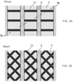
- FIG. 3A illustrates a top view of one configuration of a microstructured surface 2.
- the view of FIGS. 2A, 2B, and 2C is taken along the cross-sectional line A-A in FIG. 3A .
- the first electrodes 12 are formed as a pattern of substantially parallel wires located between and under the microfeatures 6.
- the microfeatures 6 are formed as a grating or the like that extend across the surface of the substrate 4.
- the first electrode wires 12 run along or across the spaces 13 formed between adjacent microfeatures 6.
- FIG. 3B illustrates a top view of another configuration of a microstructured surface 2.
- the first electrodes 12 are formed as a mesh pattern that is located between and under the microfeatures 6.
- FIGS. 4A-4C illustrates another embodiment of a microstructured surface 2.
- both the first electrode 12 and the second electrode 14 are placed in the space 13 formed between the microfeatures 6.
- the first electrode 12 and the second electrode 14 are electrically connected directly or via a conductor 16.
- the first electrode 12, the second electrode 14, and the electrolyte 8 are made from materials having distinctly different standard electrode potentials so that when electrolyte 8 fills the spaces 13 of the microfeatures 6 the two electrodes 12, 14 and the electrolyte 8 form an electrochemical cell (more specifically, a galvanic cell) that spontaneously generates a gas 10 on the first electrode 12.
- the overall potential of the galvanic cell should overcome the overpotential needed for gas generation on the first electrode 12.
- the magnitude of overpotential needed for gas generation on the first electrode 12 should be lower than that on the second electrode 14 so that gas is generated on electrode 12 rather than on electrode 14. Any electrolytes 8 that would generate gas in half-reaction could be used here. The same criteria of four conditions described above apply to this embodiment as well.
- FIG. 5A illustrates a top view of one configuration of a microstructured surface 2 of the embodiment of FIG. 4 .
- the view of FIGS. 2A, 2B, and 2C is taken along the cross-sectional line A-A in FIG. 3A .
- one or both of the first electrodes 12 and the second electrodes 14 are formed as a pattern of substantially parallel wires between and under the microfeatures 6.
- FIG. 5B illustrates a top view of another configuration of a microstructured surface 2.
- one or both of the first electrodes 12 and the second electrodes 14 are formed as a mesh pattern between and under the microfeatures 6.
- FIG. 4 illustrates the first electrode 12 and the second electrode 14 being located at the bottom surface of the substrate 4 between the microfeatures 6, one or both of the electrodes 12, 14, may be located on the sidewall surfaces of the microfeatures 6.
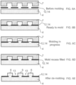
- FIG. 6A-6E illustrates a process of fabricating a microstructured surface 2 according to one embodiment. This process relies on a molding technique such as embossing or imprinting.
- the first electrode 12 or first and second electrodes 12, 14 are placed between substrate 4 and mold 7 as seen in FIGS. 6A, 6B .
- the electrodes 12, 14 may be a porous layer, a mesh, or a collection of wires, among others.
- the feature size (e.g., width of the wires) of the electrodes 12, 14 should be smaller than the openings (e.g., cavity diameter, trench width) on the mold 7 so that the electrodes 12, 14 do not substantially block the recesses.
- the substantial coverage of the recess openings would hinder the filling of the recesses during the molding step shown in FIG. 6C .
- the material or its top portion of substrate 4 flows around (or through the openings of) the electrodes 12, 14 and fill into the recesses on mold 7.
- mold 7 is separated from substrate 4, as shown in FIG. 6E .
- the electrodes 12, 14 may be completely exposed or covered with a thin residual layer of the material from substrate 4. This thin residual material may be removed by one of many etching methods known to those skilled in the art, such as plasma etching, chemical etching, or the like if necessary.
- the device may function as intended even with the electrodes 12, 14 not fully exposed, as electrochemical gas generation can still occur if the residual layer is thin enough.
- the substrate 4 may be thick, thin, rigid, or flexible, and may be made of one material or multiple layers of different materials.
- the material of microfeatures 6 maybe the same as or different from the material of substrate 4, although FIGS. 6A-6E illustrates the same material being used for the substrate 4 and microfeatures 6.
- Electrodes e.g., electrodes 12, 14
- embossing/imprinting An important aspect for the disclosed fabrication method is how to realize the electrodes (e.g., electrodes 12, 14) exposed or almost exposed in between microfeatures 6 while forming microfeatures 6 by embossing/imprinting.
- the electrodes are in a tight contact with mold 7 during the molding step. This tight contact can prevent the substrate 4 material from seeping onto the electrode surfaces, while flowing into the recesses or cavities of mold 7.
- the electrode surfaces that were in tight contact with mold 7 are exposed in between microfeatures 6 with no or little residual material on top, as shown in FIG. 6E .
- embossing/imprinting microfeatures 6 with functional materials in between the microfeatures 6 would require separate fabrication steps of molding the microfeatures 6 and placing the functional materials in between the molded microfeatures 6.
- the current invention completes the process with only a single or nearly single molding step and still does not leave much residual material on the functional materials, keeping the simplicity of traditional embossing/imprinting techniques while obtaining the functional materials exposed in between the microfeatures 6.
- this processing method is useful for other purposes as well, such as microfluidic devices for biochemical applications.
- FIG. 7 illustrates a perspective view of the microstructured surface 2 in one exemplary embodiment.
- the microfeatures 6 are gratings and the spaces 13 are formed as trenches located between adjacent microfeatures 6.
- the electrodes 12, 14 are illustrated as wires that extend generally transverse with respect to the microfeatures 6. Alternatively, the electrodes 12, 14 may be aligned parallel with the microfeatures 6.
- FIGS. 8A-8D illustrate photographs of experimental results of a microstructured surface 2 operating in the configuration of FIG. 2 .
- the FIG. 8A image show the spaces 13 between microfeatures 6 filled with gas (shown as black or dark lines perpendicular to the microfeatures 6.
- the microstructured surface 2 is in a dewetted state.
- FIG. 8B shows a substantial portion of the spaces 13 between microfeatures 6 filled with water (i.e., much of the microstructured surface 2 in a wetted state).
- the microstructured surface 2 is in a partially wetted state.
- FIG. 8C illustrates the water in the spaces being replaced by the gas 10 generated within the spaces 13 (i.e., the microstructured surface 2 being dewetted).
- FIG. 8C thus illustrates the de-wetting state whereby gas 10 is used to push our or expel the water contained in the spaces 13.
- FIG. 8D shows that nearly all the water in the spaces 13 is replaced by the gas 10, i.e., the microstructured surface 2 has returned to a dewetted state.
- the surface was not connected to any power source during the experiment.
- the gas in the microfeatures was maintained in a self-regulated and self-powered fashion.
- the microstructured surfaces 2 described herein may be used on an exterior surface of a water-borne vehicle or watercraft (e.g., boat, ship, or the like) that comes into contact with the water.
- a water-borne vehicle or watercraft e.g., boat, ship, or the like
- the choice of materials for electrodes 12, 14 is selected for particularly suitability for use in salt-water contact applications (e.g., for water-borne vehicles or watercraft that travel in seawater).
- the microstructured surfaces 2 may also be used in other applications.
- the microstructured surfaces 2 may be located on the inner surface of a pipe or conduit.
- a microstructured surface comprising: a plurality of microfeatures disposed on a substrate and defining a space located between inner surfaces of the plurality of microfeatures, wherein the inner surfaces between the plurality of microfeatures are at least partially hydrophobic; a gas generator comprising a first electrode of an electrode pair electrically connected to a second electrode of the electrode pair, the first electrode disposed within the space located between inner surfaces of the plurality of microfeatures and configured to generate a gas by a spontaneous electrochemical reaction when part of the space located between the microfeatures is filled with an electrolyte solution while the microstructured surface is submerged in the electrolyte solution. 2.
- a microstructured surface comprising: a plurality of microfeatures disposed on a substrate and defining a space located between inner surfaces of the plurality of microfeatures, wherein the inner surfaces between the plurality of microfeatures are at least partially hydrophobic; a gas generator comprising a first electrode and a second electrode of an electrode pair electrically connected to one another, the first electrode and the second electrode disposed within the space located between inner surfaces of the plurality of microfeatures and configured to generate a gas in between the microfeatures by spontaneous electrochemical reaction when part of the space is filled with an electrolyte solution while the microstructured surface is submerged in the electrolyte solution.
- microstructured surface of item 7, wherein the electrode pair is located on the substrate between microfeatures.
- the electrode pair is located on the inner surface of at least one of the microfeatures.
- the electrodes of the electrode pair have respective standard electrode potentials that generate gas by spontaneous electrochemical reaction when contacted by the electrolyte solution, and the difference between the standard electrode potential of the electrolyte and the standard electrode potential of the second electrode is, in magnitude, larger than an overpotential for gas generation at the first electrode, and wherein the overpotential at the first electrode is, in magnitude, smaller than the overpotential at the second electrode.
- a method of forming a microstructured surface comprising: depositing electrodes on a surface of a substrate; securing a mold against the surface of the substrate containing the electrodes, the mold containing a plurality of cavities therein; applying pressure between the mold and the substrate to force material from the substrate into the plurality of cavities to form a plurality of microfeatures; and separating the mold from the substrate. 14.
- the hydrophobic coating comprises polytetrafluoroethylene (PTFE).
- 22. A pipe having the microstructured surface of item 7 on an interior surface thereof.
Landscapes
- Engineering & Computer Science (AREA)
- Physics & Mathematics (AREA)
- Fluid Mechanics (AREA)
- Mechanical Engineering (AREA)
- Microelectronics & Electronic Packaging (AREA)
- General Engineering & Computer Science (AREA)
- Chemical & Material Sciences (AREA)
- Manufacturing & Machinery (AREA)
- Computer Hardware Design (AREA)
- Ocean & Marine Engineering (AREA)
- Combustion & Propulsion (AREA)
- Chemical Kinetics & Catalysis (AREA)
- Electrochemistry (AREA)
- Materials Engineering (AREA)
- Metallurgy (AREA)
- Organic Chemistry (AREA)
- Electrolytic Production Of Non-Metals, Compounds, Apparatuses Therefor (AREA)
- Physical Or Chemical Processes And Apparatus (AREA)
- Micromachines (AREA)
- Shaping Of Tube Ends By Bending Or Straightening (AREA)
Abstract
Description
- This Application claims priority to
U.S. Provisional Patent Application Nos. 62/026,474 filed on July 18, 2014 - The field of the invention generally relates to methods and devices that use microstructured hydrophobic surfaces including superhydrophobic surfaces and more particularly to methods and devices that maintain gas on the microstructured hydrophobic surfaces while they are submerged in liquid.
- By today's convention, a superhydrophobic (SHPo) surface is defined as a solid surface on which water in air forms a contact angle greater than 150 degrees. Such high contact angles have so far been found only on structured hydrophobic surfaces, the structures typically in micrometers, although not all structured hydrophobic surfaces are SHPo. A typical demonstration of SHPo surfaces is water droplets rolling around on them with little resistance. Recently, SHPo surfaces have shown promise when submerged in water (i.e., no droplet) as well because their surface structures or microfeatures can hold a gas film under water. One compelling application is drag reduction, as the gas held within (in between) the microfeatures lubricates water flows on them, effectively allowing the water to slip on the surface. How slippery a liquid flows on a solid surface is quantitatively defined as slip length, which had never been found to be more than 1 micrometer (too small to be useful for drag reduction) until the advent of SHPo surfaces. Some SHPo surfaces have demonstrated effective slip lengths in hundreds of micrometers, which are large enough to benefit even regular (i.e., large) fluidic systems. Drag reduction for turbulent flows has also been reported. For drag reduction, SHPo surfaces are considered a superior alternative to the existing bubble injection method because the stable gas upon the surfaces makes the SHPo method passive (i.e., energy efficient) and simple (i.e., easy to implement). Moreover, it has been shown that the minimized solid-liquid contact on SHPo surfaces can resist surface fouling, especially biofouling. Despite its great potential, drag reduction by SHPo surfaces has been considered strictly limited to laboratory conditions because until recently there was no indication that such SHPo surfaces could retain the gas layer long enough under real conditions.
- Considering structured hydrophobic surfaces that meet the definition of SHPo surface as a typical example, SHPo surfaces are not SHPo anymore once they lost the trapped gas and become wetted (i.e., the liquid enters in between the microfeatures). Because the wetting transition of a SHPo surface inside a liquid tends to be spontaneous, a liquid impregnation, incited by various instigators, has an irrevocable effect against drag reduction.
FIG. 1 , for example, illustrates the transition of a SHPo surface from a non-wetted state (top) to a wetted state (bottom). For example, the surface may get wet and lose its slip effect if it has defects, the liquid is under pressure, or the gas within the microfeatures diffuses away to the liquid over time. Once the SHPo surface has become wetted as illustrated inFIG. 1 , the superhydrophobicity and its attendant benefits in drag reduction , biofouling prevention , etc. are lost. - Recently, several approaches have been suggested to increase the stability of the gas layer on a structured hydrophobic (e.g., SHPo) surface submerged in liquid against its pressure (i.e., hydrostatic pressure if the liquid is water). For example, a gas layer can be pneumatically pressurized either actively or passively so that it can withstand elevated liquid pressures. Alternatively, hierarchically structures have been employed to make SHPo surfaces more resistant to liquid pressure. However, these previous improvements do not work unless the liquid pressure is relatively small (e.g., even 0.5 atm is too high). Moreover, these approaches are only preventive measures. They are ineffective once the gas layer is disrupted. The ability to maintain the gas on the structured hydrophobic surfaces under various adverse conditions is needed to utilize the gas trapping surfaces in most real applications. More desirable for robustness is the ability to restore the gas even after the surface becomes wetted by any unexpected events. A successful scheme should be able to displace the liquid that has impregnated the surface structures with new gas and restore a stable gas film.
-
U.S. Patent Application Publication No. 2013/0122195 describes a method and device for restoring and maintaining superhydrophobicity in a self-regulating manner. Here, self-regulation means the restoration and maintenance are accomplished without any discrete sensing or control mechanism. More specifically, the gas is replenished only when and where the existing gas is lost without employing any sensing mechanism to detect the loss of the existing gas or control mechanism to decide to provide new gas. - In one scheme for the self-regulated gas replenishment of the above-noted '195 publication, the replenishing gas is generated from the electrolysis of the intruding water. Since this gas generation is electrolytic, i.e., electrochemical driven by electric power, the superhydrophobic surface is electrically connected to an external power source that provides the necessary energy. To make self-regulated restoration and maintenance of superhydrophobicity more practical for implementation, however, it is highly desirable that the gas-recovering surface does not require any external assistance such as the external power source. That is to say, there is a need to provide for a surface that can maintain and restore superhydrophobicity in a "self-sufficient" manner, i.e., without the need for any external assistance, as well as the self-regulating manner.
- In another scheme for the self-regulated gas replenishment of the '195 publication, the replenishing gas is generated from the chemical reactor by chemical means, which would not need energy input from outside. While self-sufficient as well as self-regulated , the chemical gas generation was found to be inefficient and offer only a short lifetime of service. For example, in this method, there is residual electrolyte (e.g., moisture) that is left on the reactive surface which can cause the gas generation to continue even beyond the time required to restore the surface to a de-wetted state. Because of this, the chemical reaction-based gas generation surface of the type disclosed in the ` 195 publication suffers from a short lifespan. A self-controlled, self-sufficient gas maintenance method with a longer service life is desired.
- In one embodiment, a microstructured surface is disclosed with non-wetting (i.e., hydrophobic if used with or in water) microfeatures or other structures that has a self-regulated, self-powered gas generator, which generates a gas or gases through electrochemical reaction. The microfeatures may include, by way of example, trenches, ridges, posts, holes, random structures, or the like. Self-regulation refers to a gas or gases that is generated within the microfeatures when all or a portion of the microfeatures are filled with an electrolyte (i.e., electrically conductive liquid, e.g., seawater) and not generated when the microfeatures are free of the electrolyte, all without any other component to sense the loss of gas or decide the time for gas generation. Self-power refers to gas that is generated by a powering mechanism or feature built within the surface without using any external assistance such as an external source of electric power. Since electrochemical processes require electric energy, the disclosed device needs to be self-powered so as not to require an external power source such as battery. The self-powered gas generation is a subset of self-sufficient gas-generation modalities or designs that do not require external assistance. For example, gas generation by a chemical process is self-sufficient but not self-powered. This difference is important because the gas generator based on electrochemical processes has a much longer lifespan compared with the gas generator based on chemical process.
- The invention helps to maintain the gas on a gas-retaining microstructured surface (e.g., superhydrophobic surface) when submerged in a liquid. Examples of utility include (1) reducing the skin-friction drag of a solid object moving in a liquid (e.g., water vehicle or watercraft), (2) a liquid flowing past a solid surface (e.g., pipe flow), and (3) a surface that does not suffer or suffers less from biofouling under water.
- In one embodiment, a microstructured surface includes a plurality of microfeatures disposed on a substrate and defining a space located between inner surfaces of the plurality of microfeatures, wherein the inner surfaces between the plurality of microfeatures are hydrophobic. The microstructured surface includes a gas generator formed from a first electrode of an electrode pair that is electrically connected to a second electrode of the electrode pair, the first electrode disposed within the space located between inner surfaces of the plurality of microfeatures and configured to generate a gas by a spontaneous electrochemical reaction when part of the space located between the microfeatures is filled with an electrolyte solution while the microstructured surface is submerged in the electrolyte solution. Gas generation of this spontaneous electrochemical reaction is part of a galvanic reaction unlike the usual electrolytic reaction that would require the presence of an external power source. Although spontaneous instead of electrolytic, the galvanic process is still electrochemical, so that the reaction is turned on and off by the electrical state of the system. For example, when the generated gas separates the electrolyte from the electrode surface, the electric circuit is opened and the electrochemical reaction stops. The same cannot be said for chemical reactions. Even after the generated gas separates the electrolyte from the reactive surface, the residual liquid (e.g., moisture) on the surface would prolong the chemical reaction for some period of time. The prolonged reaction compromises the self-regulated nature of the gas generation and reduces the lifespan of the device.
- In another embodiment, a microstructured surface includes a plurality of microfeatures disposed on a substrate and defining a space located between inner surfaces of the plurality of microfeatures, wherein the inner surfaces between the plurality of microfeatures are hydrophobic. The microstructured surface includes a gas generator formed from a first electrode and a second electrode of an electrode pair electrically connected to one another, the first electrode and the second electrode disposed within the space located between inner surfaces of the plurality of microfeatures and configured to generate a gas in between the microfeatures by spontaneous electrochemical reaction when part of the space is filled with an electrolyte solution while the microstructured surface is submerged in the electrolyte solution.
- In another embodiment, a method of forming a microstructured surface includes depositing electrodes on a surface of a substrate; securing a mold against the surface of the substrate containing the electrodes, the mold containing a plurality of cavities therein; applying pressure between the mold and the substrate to force material from the substrate into the plurality of cavities to form a plurality of microfeatures; and separating the mold from the substrate.
- Other objects, features and advantages of the present invention will become apparent to those skilled in the art from the following detailed description. It is to be understood, however, that the detailed description and specific examples, while indicating some embodiments of the present invention are given by way of illustration and not limitation. Many changes and modifications within the scope of the present invention may be made without departing from the spirit thereof, and the invention includes all such modifications. Moreover aspects of one embodiment may be utilized in other, different embodiments.
-
-
FIG. 1 illustrates a SHPo surface according to the prior art.FIG. 1 illustrates the transition of a SHPo surface from a non-wetted state (top) to a wetted state (bottom). -
FIGS. 2A-2C illustrates one embodiment of a microstructured surface wherein one electrode of an electrode pair is disposed within the space located between adjacent microfeatures. A cross-sectional view taken along the line A-A ofFIG. 3A is shown.FIG. 2A illustrates the microstructured surface in a dewetted state.FIG. 2B illustrates the microstructured surface in a partially wetted state (e.g., one of the spaces between adjacent microstructures is filled with electrolyte).FIG. 2C illustrates the microstructured surface in a de-wetting state wherein gas that is generated at the one electrode pushes the electrolyte fluid out of the space as indicated by the arrows. -
FIGS. 3A and 3B illustrate two different electrode configurations of the embodiment ofFIG. 2 .FIG. 3A illustrates a wire pattern embodiment.FIG. 3B illustrates a mesh pattern embodiment. -
FIGS. 4A-4C illustrates another embodiment of a microstructured surface wherein an electrode pair is disposed within the space located between adjacent microfeatures. A cross-sectional view taken along the line A-A ofFIG. 5A is shown.FIG. 4A illustrates the microstructured surface in a dewetted state.FIG. 4B illustrates the microstructured surface in a partially wetted state (e.g., one of the spaces between adjacent microstructures is filled with electrolyte).FIG. 4C illustrates the microstructured surface in a de-wetting state wherein gas that is generated at the electrode pair pushes the electrolyte fluid out of the space as indicated by the arrows. -
FIGS. 5A and 5B illustrate two different electrode configurations of the embodiment ofFIG. 4 .FIG. 5A illustrates a wire pattern embodiment.FIG. 5B illustrates a mesh pattern embodiment. -
FIGS. 6A-6E illustrates a method of fabricating a microstructured hydrophobic surface according to one embodiment. -
FIG. 7 illustrates a perspective view of a microstructured hydrophobic device according to one embodiment. In this embodiment, the microstructured surface includes a series of trenches and electrodes are configured to have a pattern of wires. -
FIGS. 8A-8D illustrate a panel of photographs of a microstructured hydrophobic device illustrating operation of one embodiment. The vertical black lines are the electrodes. Horizontal black lines are the gas that is formed in the spaces between microfeatures (which appear clear, i.e., the black lines disappear where they are wetted).FIG. 8A illustrates the microstructured hydrophobic device with the surface in a dewetted state.FIG. 8B illustrates the microstructured hydrophobic device with the surface in a partially wetted state.FIG. 8C illustrates the microstructured hydrophobic device with the surface in a de-wetting state where gas is actively created and pushing out the electrolyte.FIG. 8D illustrates the microstructured hydrophobic device with the surface in a de-wetted state resembling that ofFIG. 8A . -
FIG. 2 illustrates a microstructured hydrophobic surface 2 according to one embodiment. The microstructured surface 2 includes asubstrate 4 having a plurality of microstructures ormicrofeatures 6 disposed thereon. Themicrofeatures 6 are generally oriented substantially orthogonal to thesubstrate 4. The use of the term "microfeatures 6" means, when used herein, microscopic physical features; they are commonly in micrometer scale but can be in smaller or larger scale. Themicrofeatures 6 may be arranged in an array or random configuration.Microfeatures 6 can include gratings, trenches, ridges, posts, pillars, holes, random structures, or porous materials. Thesubstrate 4 may be formed from any number of materials but, as explained in the method, may include a polymer if molding techniques are used to form the microstructured surface 2. Themicrofeatures 6 have a height in which they project relative to a surface of thesubstrate 4. The height may vary but typically is tens of microns (e.g., height = 50 µm) for drag-reduction applications and may be reduced to the single micron range (e.g., height = 5 µm) for anti-fouling applications. Themicrofeatures 6 are separated from one another by a distance. The pitch is center-center distance between thenearest neighboring microfeature 6. A liquid solution containing electrolyte 8 is disposed on the microstructured surface 2. When the space betweenneighboring microfeatures 4 is filled with agas 10, a meniscus is formed that may sag or bulge depending on the pressure difference between the liquid and the gas. - The height of the
microfeatures 6 should be high enough such that the sagging meniscus does not touch thesubstrate 4. This height is also a function of the pitch of themicrofeatures 6. It should be understood that a microstructured surface 2 includes a surface that containsmicrofeatures 6 made of or whose surface is made of a material that water or liquid of interest does not wet, i.e., forms a contact angle larger than 90° on its surface. This means the liquid is not restricted to water and may be of any kind, including water, oil, or solvent, despite the use of "hydrophobic" as described herein. - The
microfeatures 6 may be formed from the same or different material from thesubstrate 4. For instance, in some embodiments, themicrofeatures 6 may be formed from a polytetrafluoroethylene (PTFE) or the like. Themicrofeatures 6 may be made mostly from a material that is particularly hydrophobic. Alternatively, at least some portions of themicrofeatures 6 may be coated with a hydrophobic material such as PTFE or the like. In some embodiments, the top surfaces of themicrofeatures 6 may not be hydrophobic so that only the inner surfaces between themicrofeatures 6 are hydrophobic. During typical applications, a fluid of electrolyte 8 that is electrically conductive is disposed on the microstructured surface 2. A typical electrolyte 8 may include seawater or water having dissolved ionic species therein. - With reference to
FIG. 2 , the microstructured surface 2 includes afirst electrode 12 and asecond electrode 14 that are in electrical communication with one another, for example, connected to one another via aconductor 16.Conductor 16 may be a wire, electrical line, trace, tracks, vias, or the like. Thefirst electrode 12 and thesecond electrode 14 together makes a "built-in" or "self-powered" gas generator that is configured to generate agas 10 in between themicrofeatures 6. Importantly, thegas 10 is generated on theelectrode 12 without the aid of any applied power source. Instead, thefirst electrode 12, thesecond electrode 14, and the electrolyte 8 are made from materials having distinctly different standard electrode potentials (SEP) (or standard reduction potentials) so that when electrolyte 8 fills the space betweenmicrofeatures 6 the twoelectrodes gas 10 onelectrode 12. For the spontaneous reaction to occur, the overall potential of the galvanic cell should overcome the overpotential needed for gas generation on thefirst electrode 12. The overpotential is the potential difference (i.e., voltage) between a half-reaction's thermodynamically determined reduction potential and the potential at which the redox (reduction/oxidation) event is observed experimentally. For example, bubble formation ofgas 10 causes overpotential. Also, the magnitude of overpotential needed for gas generation on thefirst electrode 12 should be smaller than that on thesecond electrode 14, so that gas is generated onelectrode 12 rather than onelectrode 14. Any electrolytes 8 that would generate gas in half-reaction could be used here. - The following criteria set forth the conditions required for the operation of the microstructured surface 2 submerged in electrolyte 8 having a
first electrode 12 used for gas generation that is located in thespace 13 betweenmicrofeatures 6 and asecond electrode 14 that may or may not be located in thespace 13 as explained herein. Gas generation does not appreciably occur at thesecond electrode 14 but rather occurs at thefirst electrode 12 in this description. For the first condition, the SEP of thesecond electrode 14, denoted SEP2, should be different from the SEP of electrolyte 8, denoted SEP3 as seen inEquation 1 below:
second electrode 14 and the electrolyte 8. - The second condition is that the half-reaction of electrolyte 8 should produce
gas 10 under standard pressure and temperature. This condition is to ensure that the reaction will generate gas. - The third condition is that the difference in the theoretical standard cell potentials between the
second electrode 14 and electrolyte 8 (SEP2- SEP3) should be, in magnitude, larger than the overpotential of half-reaction of electrolyte 8 on thefirst electrode 12, denoted OP3/1 as seen in Equation 2 below:
gas 10 can be generated on thefirst electrode 12. - For the fourth condition, the overpotential of half-reaction of electrolyte 8 on the
first electrode 12, denoted OP3/1, should be, in magnitude, smaller than the overpotential of half-reaction of electrolyte 8 on thesecond electrode 14, denoted OP3/2 as seen in Equation 3 below:
gas 10 is generated mainly on thefirst electrode 12 rather than on thesecond electrode 14. All four conditions should be satisfied for the gas generation to operate properly. - Note that the above conditions can be divided into two scenarios, depending on whether the gas generation is by reduction or oxidation reaction. If the gas generation on the
first electrode 12 is by reduction reaction (e.g., 2H+ + 2e- → H2), then the SEP of thesecond electrode 14, SEP2, should be smaller than the SEP of the electrolyte, SEP3 as seen byEquation 4 below.
- In addition, the half-reaction of the electrolyte 8 should produce the gas under standard pressure and temperature. Further, the theoretical standard electrode potential between the
second electrode 14 and the electrolyte 8 (SEP2- SEP3) should be smaller (i.e., more negative) than the overpotential of half-reaction of the electrolyte 8 on thefirst electrode 12, OP3/1 as seen by Equation 5 below.
- The overpotential of half-reaction of the electrolyte 8 on the
first electrode 12, OP3/1, should be larger (i.e., less negative) than the overpotential of half-reaction of the electrolyte 8 on thesecond electrode 14 OP3/2 as seen byEquation 6 below.
- Alternatively, if the gas generation on the
first electrode 12 is by oxidation reaction (e.g., 4OH- + 4e- → O2 + 2H2O), the SEP of thesecond electrode 14 SEP2 should be larger than the SEP of the electrolyte 8 SEP3 as seen byEquation 7 below.
- The half-reaction of the electrolyte 8 should produce a gas under standard pressure and temperature. The theoretical standard electrode potential electrode potential between the
second electrode 14 and the electrolyte 8 (SEP2- SEP3) should be larger (i.e., more positive) than the overpotential of half-reaction of the electrolyte 8 on thefirst electrode 12, OP3/1 as seen by Equation 8 below.
- The overpotential of half-reaction of the electrolyte 8 on the
first electrode 12, OP3/1, should be smaller (i.e., less positive) than the overpotential of half-reaction of the electrolyte 8 on thesecond electrode 14 OP3/2 as seen by Equation 9 below.
- Specifically, according to one embodiment, if the electrolyte 8 is a neutral or alkaline water solution (e.g., seawater), the standard electrode potential is about -0.83 V from 2H2O + 2e- ↔ H2(g) + 2OH-. If the electrolyte 8 is an acid water solution, the standard electrode potential is 0 V from 2H+ + 2e- ↔H2(g). Once the electrolyte 8 is chosen, possible materials combinations for the
first electrode 12 and thesecond electrode 14 could be obtained, satisfying the constraints stated above regarding standard electrode potential and over-potential. For a specific example, thefirst electrode 12 may be made from a metal or metal alloy containing nickel, thesecond electrode 14 may be made from a metal or metal alloy containing magnesium, and the electrolyte 8 may be seawater (although other electrolytes may also be used such as fresh water, acid solutions, basic solutions, and the like). In this case, thegas 10 that is produced is hydrogen at thefirst electrode 12. Table 1 below lists various materials and SEP and overpotential values that have been tested with successful results.Table 1 Name Material Half reaction SEP |OP| (H2 evolution at 25 °C) First Electrode Nickel N/A (inert) N/A 0.28 V Second Electrode Magnesium Mg2+(aq) + 2e- ↔ Mg(s) -2.372 V ∼1 V Electrolyte Seawater 2H2O(l) + 2e- ↔ H2(g) + 2OH-(aq) -0.8277 V N/A - Where and when at least a portion of the space between
microfeatures 6 are filled with the electrolyte 8 and contact the gas generating electrode, gas 10 (e.g., hydrogen) is automatically generated by the spontaneous electrochemical reaction (i.e., galvanic reaction) that takes place. Themicrofeatures 6 are designed and spaced such that thegas 10 that is generated on theelectrode 12 is trapped and grows within the localized space, gap, or well 13 formed betweenadjacent microfeatures 6. Once the volume of generatedgas 10 has grown in size to the top (e.g., upper surface) of themicrofeatures 6 thegas 10 proceeds to extend laterally in between themicrofeatures 6 across the microstructured surface 2. In this regard, the microstructured surface 2 can be restored from a partially or fully wetted state back into a non-wetted state. In one embodiment, thefirst electrode 12 is disposed on or embedded in thesubstrate 4.FIGS. 2A-2C illustrates thefirst electrode 12 located on thesubstrate 4 within thespace 13 formed betweenadjacent microfeatures 6. In this embodiment, thefirst electrode 12 is located on a bottom surface of space orgap 13 located between themicrofeatures 6. Alternatively, thefirst electrode 12 may be located on the sidewall surface of themicrofeatures 6. Thus, thefirst electrode 12 can be located in any location between themicrofeatures 6, wherein betweenmicrofeatures 6 refers to thespaces 13 and inner surfaces between microfeatures 6 (excluding the top or exposed surfaces of the microfeatures 6). Note that in the embodiment ofFIGS. 2A-2C , thesecond electrode 14 is not located between themicrofeatures 6. Instead, thesecond electrode 14 is located outside of theinternal space 13 created by themicrofeatures 6. - The
gas 10 that is generated by thefirst electrode 12 is trapped and grows in the localized space or well 13 formed betweenadjacent microfeatures 6. It should be noted that gas generation is self-regulated in this embodiment. In particular, the electrochemical circuit is "closed" and gas generation occurs only if the microstructured surface 2 becomes partially or fully wetted. Once the electrolyte 8 invades thespace 13 betweenadjacent microfeatures 6 the circuit is closed between thefirst electrode 12 and thesecond electrode 14 and the electrochemical reaction proceeds, thereby liberatinggas 10 within thespaces 13 located between themicrofeatures 6. After sufficient gas generation, the electrochemical circuit then becomes "open" and the electrochemical reaction stops. This feature is particularly advantageous because there is no need for any sensing and controlling circuitry to switch the gas generator (i.e., electrode) on or off; in other words, the gas generation is self-regulated to respond to presence of electrolyte 8 in between themicrofeatures 6. - The gas generation occurs spontaneously without connecting the microstructured surface 2 to any external power source (e.g., battery); in other words, the gas generation is self-sufficient. However, since the gas generation is the product of an electrochemical reaction (i.e., powered electrically albeit using internal energy) rather than pure chemical reaction (i.e., no electric power involved), one may call the disclosed method of gas generation not only self-sufficient but also "self-powered." In addition and related to the above difference, it is worth noting that the gas generator (i.e., electrode) located in between the
microfeatures 6 is not a reactant in the current self-powered, electrochemical reaction. Self-powering and self-regulating the gas generation, the microstructured surface 2 has the built-in ability to maintain thegas 10 trapped in between itsmicrofeatures 6. -
FIG. 3A illustrates a top view of one configuration of a microstructured surface 2. The view ofFIGS. 2A, 2B, and 2C is taken along the cross-sectional line A-A inFIG. 3A . In this embodiment, thefirst electrodes 12 are formed as a pattern of substantially parallel wires located between and under themicrofeatures 6. Themicrofeatures 6 are formed as a grating or the like that extend across the surface of thesubstrate 4. Thefirst electrode wires 12 run along or across thespaces 13 formed betweenadjacent microfeatures 6.FIG. 3B illustrates a top view of another configuration of a microstructured surface 2. In this embodiment, thefirst electrodes 12 are formed as a mesh pattern that is located between and under themicrofeatures 6. -
FIGS. 4A-4C illustrates another embodiment of a microstructured surface 2. In this embodiment, both thefirst electrode 12 and thesecond electrode 14 are placed in thespace 13 formed between themicrofeatures 6. Again, thefirst electrode 12 and thesecond electrode 14 are electrically connected directly or via aconductor 16. Thefirst electrode 12, thesecond electrode 14, and the electrolyte 8 are made from materials having distinctly different standard electrode potentials so that when electrolyte 8 fills thespaces 13 of themicrofeatures 6 the twoelectrodes gas 10 on thefirst electrode 12. For the spontaneous reaction to occur, the overall potential of the galvanic cell should overcome the overpotential needed for gas generation on thefirst electrode 12. Also, the magnitude of overpotential needed for gas generation on thefirst electrode 12 should be lower than that on thesecond electrode 14 so that gas is generated onelectrode 12 rather than onelectrode 14. Any electrolytes 8 that would generate gas in half-reaction could be used here. The same criteria of four conditions described above apply to this embodiment as well. -
FIG. 5A illustrates a top view of one configuration of a microstructured surface 2 of the embodiment ofFIG. 4 . The view ofFIGS. 2A, 2B, and 2C is taken along the cross-sectional line A-A inFIG. 3A . In this embodiment, one or both of thefirst electrodes 12 and thesecond electrodes 14 are formed as a pattern of substantially parallel wires between and under themicrofeatures 6.FIG. 5B illustrates a top view of another configuration of a microstructured surface 2. In this embodiment, one or both of thefirst electrodes 12 and thesecond electrodes 14 are formed as a mesh pattern between and under themicrofeatures 6. Again, whileFIG. 4 illustrates thefirst electrode 12 and thesecond electrode 14 being located at the bottom surface of thesubstrate 4 between themicrofeatures 6, one or both of theelectrodes microfeatures 6. -
FIG. 6A-6E illustrates a process of fabricating a microstructured surface 2 according to one embodiment. This process relies on a molding technique such as embossing or imprinting. First, thefirst electrode 12 or first andsecond electrodes substrate 4 andmold 7 as seen inFIGS. 6A, 6B . Theelectrodes electrodes mold 7 so that theelectrodes FIG. 6C . During the molding step ofFIG. 6C , under applied pressure and optionally at an elevated temperature as well, the material or its top portion ofsubstrate 4 flows around (or through the openings of) theelectrodes mold 7. After themold 7 is full as shown inFIG. 6D ,mold 7 is separated fromsubstrate 4, as shown inFIG. 6E . At this point, theelectrodes substrate 4. This thin residual material may be removed by one of many etching methods known to those skilled in the art, such as plasma etching, chemical etching, or the like if necessary. The device may function as intended even with theelectrodes substrate 4 may be thick, thin, rigid, or flexible, and may be made of one material or multiple layers of different materials. The material ofmicrofeatures 6 maybe the same as or different from the material ofsubstrate 4, althoughFIGS. 6A-6E illustrates the same material being used for thesubstrate 4 andmicrofeatures 6. - An important aspect for the disclosed fabrication method is how to realize the electrodes (e.g.,
electrodes 12, 14) exposed or almost exposed in betweenmicrofeatures 6 while formingmicrofeatures 6 by embossing/imprinting. As shown inFIG. 6C and 6D , the electrodes are in a tight contact withmold 7 during the molding step. This tight contact can prevent thesubstrate 4 material from seeping onto the electrode surfaces, while flowing into the recesses or cavities ofmold 7. After de-molding, the electrode surfaces that were in tight contact withmold 7 are exposed in betweenmicrofeatures 6 with no or little residual material on top, as shown inFIG. 6E . Usually, embossing/imprinting microfeatures 6 with functional materials in between themicrofeatures 6 would require separate fabrication steps of molding themicrofeatures 6 and placing the functional materials in between the moldedmicrofeatures 6. The current invention completes the process with only a single or nearly single molding step and still does not leave much residual material on the functional materials, keeping the simplicity of traditional embossing/imprinting techniques while obtaining the functional materials exposed in between themicrofeatures 6. Although developed for the gas-retaining device above, this processing method is useful for other purposes as well, such as microfluidic devices for biochemical applications. -
FIG. 7 illustrates a perspective view of the microstructured surface 2 in one exemplary embodiment. In this embodiment, themicrofeatures 6 are gratings and thespaces 13 are formed as trenches located betweenadjacent microfeatures 6. Theelectrodes microfeatures 6. Alternatively, theelectrodes microfeatures 6. -
FIGS. 8A-8D illustrate photographs of experimental results of a microstructured surface 2 operating in the configuration ofFIG. 2 . While fully submerged in water (i.e., seawater), theFIG. 8A image show thespaces 13 betweenmicrofeatures 6 filled with gas (shown as black or dark lines perpendicular to themicrofeatures 6. In the state ofFIG. 8A , the microstructured surface 2 is in a dewetted state.FIG. 8B shows a substantial portion of thespaces 13 betweenmicrofeatures 6 filled with water (i.e., much of the microstructured surface 2 in a wetted state). In the state ofFIG. 8B , the microstructured surface 2 is in a partially wetted state.FIG. 8C illustrates the water in the spaces being replaced by thegas 10 generated within the spaces 13 (i.e., the microstructured surface 2 being dewetted).FIG. 8C thus illustrates the de-wetting state wherebygas 10 is used to push our or expel the water contained in thespaces 13.FIG. 8D shows that nearly all the water in thespaces 13 is replaced by thegas 10, i.e., the microstructured surface 2 has returned to a dewetted state. The surface was not connected to any power source during the experiment. The gas in the microfeatures was maintained in a self-regulated and self-powered fashion. - The microstructured surfaces 2 described herein may be used on an exterior surface of a water-borne vehicle or watercraft (e.g., boat, ship, or the like) that comes into contact with the water. In one particular embodiment, the choice of materials for
electrodes - While embodiments have been shown and described, various modifications may be made without departing from the scope of the inventive concepts disclosed herein. The invention(s), therefore, should not be limited, except to the following claims, and their equivalents.
- The invention can also be directed to the following items: 1. A microstructured surface comprising: a plurality of microfeatures disposed on a substrate and defining a space located between inner surfaces of the plurality of microfeatures, wherein the inner surfaces between the plurality of microfeatures are at least partially hydrophobic; a gas generator comprising a first electrode of an electrode pair electrically connected to a second electrode of the electrode pair, the first electrode disposed within the space located between inner surfaces of the plurality of microfeatures and configured to generate a gas by a spontaneous electrochemical reaction when part of the space located between the microfeatures is filled with an electrolyte solution while the microstructured surface is submerged in the electrolyte solution. 2. The microstructured surface of
item 1, wherein the first electrode of the electrode pair is located on the substrate between microfeatures. 3. The microstructured surface ofitem 1, wherein the first electrode of the electrode pair is located on the inner surface of at least one of the microfeatures. 4. The microstructured surface ofitem 1, wherein the first electrode and the second electrode of the electrode pair have respective standard electrode potentials that generate gas by spontaneous electrochemical reaction when contacted by the electrolyte solution, and the difference between the standard electrode potential of the electrolyte and the standard electrode potential of the second electrode is, in magnitude, larger than an overpotential for gas generation at the first electrode, and wherein the overpotential at the first electrode is, in magnitude, smaller than the overpotential at the second electrode. 5. The microstructured surface ofitem 1, wherein the first electrode of the electrode pair comprises one of a trace, track, porous layer, mesh, or wire. 6. The microstructured surface ofitem 1, wherein the first electrode comprises nickel and the second electrode comprises magnesium. 7. A microstructured surface comprising: a plurality of microfeatures disposed on a substrate and defining a space located between inner surfaces of the plurality of microfeatures, wherein the inner surfaces between the plurality of microfeatures are at least partially hydrophobic; a gas generator comprising a first electrode and a second electrode of an electrode pair electrically connected to one another, the first electrode and the second electrode disposed within the space located between inner surfaces of the plurality of microfeatures and configured to generate a gas in between the microfeatures by spontaneous electrochemical reaction when part of the space is filled with an electrolyte solution while the microstructured surface is submerged in the electrolyte solution. 8. The microstructured surface ofitem 7, wherein the electrode pair is located on the substrate between microfeatures. 9. The microstructured surface ofitem 7, wherein the electrode pair is located on the inner surface of at least one of the microfeatures. 10. The microstructured surface ofitem 7, wherein the electrodes of the electrode pair have respective standard electrode potentials that generate gas by spontaneous electrochemical reaction when contacted by the electrolyte solution, and the difference between the standard electrode potential of the electrolyte and the standard electrode potential of the second electrode is, in magnitude, larger than an overpotential for gas generation at the first electrode, and wherein the overpotential at the first electrode is, in magnitude, smaller than the overpotential at the second electrode. 11. The microstructured surface ofitem 7, wherein the electrode pair comprise one of a trace, track, porous layer, mesh, or wires. 12. The microstructured surface ofitem 7, wherein the first electrode comprises nickel and the second electrode comprises magnesium. 13. A method of forming a microstructured surface comprising: depositing electrodes on a surface of a substrate; securing a mold against the surface of the substrate containing the electrodes, the mold containing a plurality of cavities therein; applying pressure between the mold and the substrate to force material from the substrate into the plurality of cavities to form a plurality of microfeatures; and separating the mold from the substrate. 14. The method ofitem 13, wherein pressure is applied at an elevated temperature. 15. The method ofitem 13, further comprising removing any substrate material covering the electrodes after separating the mold from the substrate. 16. The method ofitem 13, further comprising coating the plurality of microfeatures with a hydrophobic layer. 17. The method ofitem 16, wherein the hydrophobic coating comprises polytetrafluoroethylene (PTFE). 18. The method ofitem 13, further comprising connecting the electrodes on the substrate to another electrode formed from a different material. 19. A water-borne vehicle or watercraft having the microstructured surface ofitem 1 on at least a portion of a water-contacting surface. 20. A water-borne vehicle or watercraft having the microstructured surface ofitem 7 on at least a portion of a water-contacting surface. 21. A pipe having the microstructured surface ofitem 1 on an interior surface thereof. 22. A pipe having the microstructured surface ofitem 7 on an interior surface thereof.
Claims (15)
- A method of forming a microstructured surface comprising:depositing electrodes on a surface of a substrate;securing a mold against the surface of the substrate containing the electrodes, the mold containing a plurality of cavities therein;applying pressure between the mold and the substrate to force material from the substrate into the plurality of cavities to form a plurality of microfeatures; andseparating the mold from the substrate.
- The method of claim 1, wherein pressure is applied at an elevated temperature.
- The method of claim 1, further comprising removing any substrate material covering the electrodes after separating the mold from the substrate.
- The method of claim 1, further comprising coating the plurality of microfeatures with a hydrophobic layer.
- The method of claim 4, wherein the hydrophobic coating comprises polytetrafluoroethylene (PTFE).
- The method of claim 1, further comprising connecting the electrodes on the substrate to another electrode formed from a different material.
- The method of claim 1, wherein the substrate comprises a polymer.
- The method of claim 1, wherein the substrate comprises polytetrafluoroethylene (PTFE).
- The method of claim 1, wherein the substrate comprises multiple layers of different materials and wherein the microfeatures are formed of a material different from the substrate.
- The method of claim 1, wherein the plurality of microfeatures have a height within the range of single microns to tens of microns.
- The method of claim 1, wherein an opening dimension of the plurality of cavities is larger than a width dimension of the electrodes.
- The method of claim 1, wherein the electrodes comprise a porous layer, mesh, or a collection of wires.
- The method of claim 1, wherein the electrodes comprise a first electrode and second electrode, wherein the first electrode and the second electrode have different standard electrode potentials (SEP).
- The method of claim 1, wherein the electrodes are in tight contact with the mold during the molding step so that the electrode surfaces are exposed with no or little residual material on top when the mold is separated from the substrate.
- A microstructured surface made by the process of claim 1, wherein the microstructured surface is located on a water-contacting surface of a water-borne vehicle, watercraft, or an interior surface of a pipe
Applications Claiming Priority (3)
| Application Number | Priority Date | Filing Date | Title |
|---|---|---|---|
| US201462026474P | 2014-07-18 | 2014-07-18 | |
| PCT/US2015/040777 WO2016011271A1 (en) | 2014-07-18 | 2015-07-16 | Device and method for gas maintenance in microfeatures on a submerged surface |
| EP15822774.4A EP3169624B1 (en) | 2014-07-18 | 2015-07-16 | Device for gas maintenance in microfeatures on a submerged surface |
Related Parent Applications (1)
| Application Number | Title | Priority Date | Filing Date |
|---|---|---|---|
| EP15822774.4A Division EP3169624B1 (en) | 2014-07-18 | 2015-07-16 | Device for gas maintenance in microfeatures on a submerged surface |
Publications (2)
| Publication Number | Publication Date |
|---|---|
| EP4303451A1 true EP4303451A1 (en) | 2024-01-10 |
| EP4303451B1 EP4303451B1 (en) | 2026-04-08 |
Family
ID=55079059
Family Applications (2)
| Application Number | Title | Priority Date | Filing Date |
|---|---|---|---|
| EP23195269.8A Active EP4303451B1 (en) | 2014-07-18 | 2015-07-16 | Device for gas maintenance in microfeatures on a submerged surface |
| EP15822774.4A Active EP3169624B1 (en) | 2014-07-18 | 2015-07-16 | Device for gas maintenance in microfeatures on a submerged surface |
Family Applications After (1)
| Application Number | Title | Priority Date | Filing Date |
|---|---|---|---|
| EP15822774.4A Active EP3169624B1 (en) | 2014-07-18 | 2015-07-16 | Device for gas maintenance in microfeatures on a submerged surface |
Country Status (6)
| Country | Link |
|---|---|
| US (2) | US20180320717A1 (en) |
| EP (2) | EP4303451B1 (en) |
| JP (1) | JP6773638B2 (en) |
| KR (1) | KR102378963B1 (en) |
| CN (1) | CN107074524B (en) |
| WO (1) | WO2016011271A1 (en) |
Families Citing this family (11)
| Publication number | Priority date | Publication date | Assignee | Title |
|---|---|---|---|---|
| JP6773638B2 (en) | 2014-07-18 | 2020-10-21 | ザ リージェンツ オブ ザ ユニバーシティ オブ カリフォルニア | Devices and methods for retaining gas in microfeatures on the surface of the liquid |
| US10787231B2 (en) * | 2016-07-29 | 2020-09-29 | California Institute Of Technology | Systems, methods, and apparatuses for reducing hydrodynamic frictional drag |
| CN109399548A (en) * | 2017-08-17 | 2019-03-01 | 南京理工大学 | A kind of device and preparation method thereof automatically replying stable ultra-hydrophobic state |
| DE102018003141B4 (en) * | 2018-04-17 | 2019-11-07 | Baden-Württemberg Stiftung Ggmbh | Structured surface and device comprising these and their use |
| CN112026983B (en) * | 2020-08-27 | 2021-09-17 | 厦门大学 | Electrode wall surface micro-pit electrolysis micro-bubble generating device based on micro-drill hole making |
| CN114182275B (en) * | 2021-11-22 | 2023-07-14 | 大连交通大学 | Underwater drag-reducing surface with alternating structure of gas production and gas capture and its preparation method |
| CN114212184B (en) * | 2022-01-26 | 2024-05-17 | 西北工业大学 | Underwater wall surface gas constraint system and preparation method |
| CN121079246A (en) * | 2023-04-07 | 2025-12-05 | 加利福尼亚大学董事会 | Air film capturing groove and application thereof |
| CN116714712B (en) * | 2023-06-29 | 2023-12-08 | 中国船舶集团有限公司第七一九研究所 | Microstructure of drag reduction function surface and forming method thereof |
| CN117734872B (en) * | 2023-11-24 | 2024-07-19 | 中国人民解放军国防科技大学 | A drag reduction device for underwater vehicles based on permeable air membrane |
| GB202413966D0 (en) * | 2024-09-23 | 2024-11-06 | Tokamak Energy Ltd | Apparatus for use with electrically conductive fluid |
Citations (2)
| Publication number | Priority date | Publication date | Assignee | Title |
|---|---|---|---|---|
| US20120261264A1 (en) * | 2008-07-18 | 2012-10-18 | Advanced Liquid Logic, Inc. | Droplet Operations Device |
| US20130122195A1 (en) | 2010-07-27 | 2013-05-16 | The Regents Of The University Of California | Method and device for restoring and maintaining superhydrophobicity under liquid |
Family Cites Families (40)
| Publication number | Priority date | Publication date | Assignee | Title |
|---|---|---|---|---|
| NL113269C (en) | 1957-05-22 | 1900-01-01 | ||
| US3256504A (en) * | 1961-01-11 | 1966-06-14 | Fidelman Morris | Galvanic hydrogen producer |
| US4554222A (en) | 1980-08-18 | 1985-11-19 | Solomon Zaromb | Metal-consuming power generation apparatus and methods |
| US4463063A (en) | 1982-07-16 | 1984-07-31 | Engelhard Corporation | Hydrogen generator |
| JPH07211330A (en) * | 1994-01-24 | 1995-08-11 | Yuasa Corp | Seawater battery |
| JPH07211331A (en) * | 1994-01-26 | 1995-08-11 | Yuasa Corp | Seawater battery |
| JPH09262563A (en) | 1996-03-29 | 1997-10-07 | Mitsui Eng & Shipbuild Co Ltd | Method for retaining gas film formed on submerged surface of structure |
| US5935412A (en) * | 1997-06-17 | 1999-08-10 | Atlantis Limited Partnership | Method and apparatus for eliminating odors in sewage systems |
| DE69903641T2 (en) | 1998-07-29 | 2003-06-26 | W.A. Sanders Papierfabriek Coldenhove B.V., Eerbeek | TRANSFER PAPER FOR INK JET PRINTING |
| DE10144259A1 (en) | 2001-09-08 | 2003-03-27 | Bernd Spaeth | Body contacting media has surfaces with micrometric- or nanometric structuring, adapted to the respective media |
| AU2003272194A1 (en) | 2002-04-26 | 2004-02-23 | Board Of Regents | Methods for reducing the viscous drag on a surface and drag reducing device |
| KR20050085631A (en) * | 2002-12-13 | 2005-08-29 | 코닌클리케 필립스 일렉트로닉스 엔.브이. | Field emission device, and method of manufacturing such a device |
| KR20040063019A (en) * | 2003-01-04 | 2004-07-12 | 엘지전자 주식회사 | Method of forming barrier rib on the lower substrate of plasma display panel |
| US7227235B2 (en) * | 2003-11-18 | 2007-06-05 | Lucent Technologies Inc. | Electrowetting battery having a nanostructured electrode surface |
| US7749646B2 (en) * | 2004-03-18 | 2010-07-06 | Alcatel-Lucent Usa Inc. | Reversibly-activated nanostructured battery |
| US7323033B2 (en) * | 2004-04-30 | 2008-01-29 | Lucent Technologies Inc. | Nanostructured surfaces having variable permeability |
| WO2006132640A2 (en) | 2004-06-14 | 2006-12-14 | Arizona Board Of Regents For And On Behalf Of Arizona State University | Light-driven microfluidic devices and amplification of stimulus-induced wetting |
| US7150904B2 (en) | 2004-07-27 | 2006-12-19 | Ut-Battelle, Llc | Composite, ordered material having sharp surface features |
| US20060029808A1 (en) | 2004-08-06 | 2006-02-09 | Lei Zhai | Superhydrophobic coatings |
| US7459197B2 (en) | 2004-11-30 | 2008-12-02 | Lucent Technologies Inc. | Reversibly adaptive rough micro- and nano-structures |
| JP2006168147A (en) * | 2004-12-15 | 2006-06-29 | Aitesu:Kk | Manufacturing method of fine structure using organic-inorganic hybrid material and nanoimprint technology, and fine structure |
| US7662653B2 (en) * | 2005-02-10 | 2010-02-16 | Cardiomems, Inc. | Method of manufacturing a hermetic chamber with electrical feedthroughs |
| JP4253028B2 (en) | 2005-04-12 | 2009-04-08 | 古河電気工業株式会社 | Liquid actuator |
| US8287808B2 (en) | 2005-09-15 | 2012-10-16 | Alcatel Lucent | Surface for reversible wetting-dewetting |
| US20070059213A1 (en) | 2005-09-15 | 2007-03-15 | Lucent Technologies Inc. | Heat-induced transitions on a structured surface |
| US7449649B2 (en) | 2006-05-23 | 2008-11-11 | Lucent Technologies Inc. | Liquid switch |
| US8047235B2 (en) * | 2006-11-30 | 2011-11-01 | Alcatel Lucent | Fluid-permeable body having a superhydrophobic surface |
| JP2008195598A (en) | 2007-02-14 | 2008-08-28 | Samsung Electro-Mechanics Co Ltd | Hydrogen generator and fuel cell power generation system |
| CN101679078B (en) * | 2007-05-24 | 2013-04-03 | 数字化生物系统 | Digital Microfluidics Based on Electrowetting |
| EP2188919B1 (en) * | 2007-08-15 | 2016-04-20 | LG Electronics Inc. | Dedicated signature allocation and choice |
| US7952187B2 (en) * | 2008-03-31 | 2011-05-31 | General Electric Company | System and method of forming a wafer scale package |
| US20100028604A1 (en) | 2008-08-01 | 2010-02-04 | The Ohio State University | Hierarchical structures for superhydrophobic surfaces and methods of making |
| KR20100076439A (en) | 2008-12-26 | 2010-07-06 | 부산대학교 산학협력단 | The method to attach micro bubble array on a plate surface |
| US20100330340A1 (en) | 2009-05-12 | 2010-12-30 | University Of Massachusetts | Superhydrophobic surfaces for drag reduction |
| KR101049823B1 (en) * | 2009-09-30 | 2011-07-15 | 삼성에스디아이 주식회사 | Plasma display device |
| JP2011178609A (en) * | 2010-03-02 | 2011-09-15 | Kawasaki Heavy Ind Ltd | Method for producing hydrogen gas |
| TW201238836A (en) * | 2011-03-30 | 2012-10-01 | Univ Nat Kaohsiung Marine | A device with microbubble-induced superhydrophobic surface for drag reduction and antifouling in seagoing ship |
| KR101866501B1 (en) | 2011-09-28 | 2018-06-12 | 삼성전자주식회사 | Superhydrophobic electromagnetic field sheilding material and method of preparing the same |
| US20130220813A1 (en) * | 2012-02-29 | 2013-08-29 | Massachusetts Institute Of Technology | Articles and methods for modifying condensation on surfaces |
| JP6773638B2 (en) | 2014-07-18 | 2020-10-21 | ザ リージェンツ オブ ザ ユニバーシティ オブ カリフォルニア | Devices and methods for retaining gas in microfeatures on the surface of the liquid |
-
2015
- 2015-07-16 JP JP2017502709A patent/JP6773638B2/en active Active
- 2015-07-16 WO PCT/US2015/040777 patent/WO2016011271A1/en not_active Ceased
- 2015-07-16 EP EP23195269.8A patent/EP4303451B1/en active Active
- 2015-07-16 KR KR1020177004126A patent/KR102378963B1/en active Active
- 2015-07-16 CN CN201580049848.6A patent/CN107074524B/en active Active
- 2015-07-16 EP EP15822774.4A patent/EP3169624B1/en active Active
- 2015-07-16 US US15/325,421 patent/US20180320717A1/en not_active Abandoned
-
2023
- 2023-07-21 US US18/357,093 patent/US12365585B2/en active Active
Patent Citations (2)
| Publication number | Priority date | Publication date | Assignee | Title |
|---|---|---|---|---|
| US20120261264A1 (en) * | 2008-07-18 | 2012-10-18 | Advanced Liquid Logic, Inc. | Droplet Operations Device |
| US20130122195A1 (en) | 2010-07-27 | 2013-05-16 | The Regents Of The University Of California | Method and device for restoring and maintaining superhydrophobicity under liquid |
Also Published As
| Publication number | Publication date |
|---|---|
| JP6773638B2 (en) | 2020-10-21 |
| JP2017532207A (en) | 2017-11-02 |
| US12365585B2 (en) | 2025-07-22 |
| EP3169624A4 (en) | 2018-05-02 |
| KR20170035951A (en) | 2017-03-31 |
| EP4303451B1 (en) | 2026-04-08 |
| US20240018980A1 (en) | 2024-01-18 |
| CN107074524B (en) | 2020-01-17 |
| US20180320717A1 (en) | 2018-11-08 |
| KR102378963B1 (en) | 2022-03-24 |
| EP3169624B1 (en) | 2023-09-06 |
| WO2016011271A1 (en) | 2016-01-21 |
| CN107074524A (en) | 2017-08-18 |
| EP3169624A1 (en) | 2017-05-24 |
Similar Documents
| Publication | Publication Date | Title |
|---|---|---|
| US12365585B2 (en) | Method of forming a microstructured surface | |
| US10125271B2 (en) | Method and device for restoring and maintaining superhydrophobicity under liquid | |
| Hengsteler et al. | Electrochemical 3D micro‐and nanoprinting: current state and future perspective | |
| Sequeira et al. | Bipolar electrochemistry, a focal point of future research | |
| JP6366605B2 (en) | Seawater desalination without membranes | |
| JP4763277B2 (en) | Fabrication of nano object arrays | |
| WO2005088759A2 (en) | Microfluidic electrochemical reactors | |
| Wang | Template electrodeposition of catalytic nanomotors | |
| Xu et al. | Self-powered plastron preservation and one-step molding of semiactive superhydrophobic surfaces | |
| Leïchlé et al. | Integration of lateral porous silicon membranes into planar microfluidics | |
| Tsutsui et al. | Scalability of nanopore osmotic energy conversion | |
| US11251417B2 (en) | Methods and apparatus for controlling electrodeposition using surface charge properties | |
| KR100993925B1 (en) | Manufacturing method of three-dimensional shaped structure with hydrophobic surface using metal foil | |
| US20180375109A1 (en) | Electrochemical cells and batteries | |
| Wang et al. | Understanding the intrinsic rectification properties of nanoporous anodic alumina by selective chemical etching | |
| KR100988932B1 (en) | Fabricating Method of 3D Shape Structure Having Hydrophobic Surface Using Metal Foil | |
| US12528052B2 (en) | Ratchet-based ion pumping membrane systems | |
| Nithyanandam | A Study of Electrochemically Controlled Interfacial Tension of Eutectic Gallium Indium | |
| Obata et al. | Electrochemical bidirectional micropump for processing of liquid plugs | |
| Kjeang | Microfluidic fuel cells | |
| Zaouk | Carbon MEMS from the nanoscale to the macroscale: Novel fabrication techniques and applications in electrochemistry | |
| Patil | Enhancement of Pool Boiling Heat Transfer using a Combination of Open Microchannels and Microporous Surfaces | |
| Fang et al. | Plastron Recovery in Hydrophobic Grooves by Electrolysis | |
| CN109399548A (en) | A kind of device and preparation method thereof automatically replying stable ultra-hydrophobic state | |
| Armutlulu | Deterministically Engineered, High Power Density Energy Storage Devices Enabled by MEMS Technologies |
Legal Events
| Date | Code | Title | Description |
|---|---|---|---|
| PUAI | Public reference made under article 153(3) epc to a published international application that has entered the european phase |
Free format text: ORIGINAL CODE: 0009012 |
|
| STAA | Information on the status of an ep patent application or granted ep patent |
Free format text: STATUS: THE APPLICATION HAS BEEN PUBLISHED |
|
| AC | Divisional application: reference to earlier application |
Ref document number: 3169624 Country of ref document: EP Kind code of ref document: P |
|
| AK | Designated contracting states |
Kind code of ref document: A1 Designated state(s): AL AT BE BG CH CY CZ DE DK EE ES FI FR GB GR HR HU IE IS IT LI LT LU LV MC MK MT NL NO PL PT RO RS SE SI SK SM TR |
|
| STAA | Information on the status of an ep patent application or granted ep patent |
Free format text: STATUS: REQUEST FOR EXAMINATION WAS MADE |
|
| 17P | Request for examination filed |
Effective date: 20240709 |
|
| RBV | Designated contracting states (corrected) |
Designated state(s): AL AT BE BG CH CY CZ DE DK EE ES FI FR GB GR HR HU IE IS IT LI LT LU LV MC MK MT NL NO PL PT RO RS SE SI SK SM TR |
|
| GRAP | Despatch of communication of intention to grant a patent |
Free format text: ORIGINAL CODE: EPIDOSNIGR1 |
|
| STAA | Information on the status of an ep patent application or granted ep patent |
Free format text: STATUS: GRANT OF PATENT IS INTENDED |
|
| INTG | Intention to grant announced |
Effective date: 20251031 |
|
| GRAS | Grant fee paid |
Free format text: ORIGINAL CODE: EPIDOSNIGR3 |
|
| GRAA | (expected) grant |
Free format text: ORIGINAL CODE: 0009210 |
|
| STAA | Information on the status of an ep patent application or granted ep patent |
Free format text: STATUS: THE PATENT HAS BEEN GRANTED |
|
| AC | Divisional application: reference to earlier application |
Ref document number: 3169624 Country of ref document: EP Kind code of ref document: P |
|
| AK | Designated contracting states |
Kind code of ref document: B1 Designated state(s): AL AT BE BG CH CY CZ DE DK EE ES FI FR GB GR HR HU IE IS IT LI LT LU LV MC MK MT NL NO PL PT RO RS SE SI SK SM TR |
|
| REG | Reference to a national code |
Ref country code: CH Ref legal event code: F10 Free format text: ST27 STATUS EVENT CODE: U-0-0-F10-F00 (AS PROVIDED BY THE NATIONAL OFFICE) Effective date: 20260408 Ref country code: GB Ref legal event code: FG4D |
|
| REG | Reference to a national code |
Ref country code: DE Ref legal event code: R096 Ref document number: 602015093240 Country of ref document: DE |