EP4303443B1 - Pneumatic inlet/blowdown valve assembly - Google Patents
Pneumatic inlet/blowdown valve assembly Download PDFInfo
- Publication number
- EP4303443B1 EP4303443B1 EP23182531.6A EP23182531A EP4303443B1 EP 4303443 B1 EP4303443 B1 EP 4303443B1 EP 23182531 A EP23182531 A EP 23182531A EP 4303443 B1 EP4303443 B1 EP 4303443B1
- Authority
- EP
- European Patent Office
- Prior art keywords
- piston
- chamber
- valve
- blowdown valve
- inlet
- Prior art date
- Legal status (The legal status is an assumption and is not a legal conclusion. Google has not performed a legal analysis and makes no representation as to the accuracy of the status listed.)
- Active
Links
Images



Classifications
-
- G—PHYSICS
- G05—CONTROLLING; REGULATING
- G05D—SYSTEMS FOR CONTROLLING OR REGULATING NON-ELECTRIC VARIABLES
- G05D16/00—Control of fluid pressure
- G05D16/20—Control of fluid pressure characterised by the use of electric means
- G05D16/2006—Control of fluid pressure characterised by the use of electric means with direct action of electric energy on controlling means
- G05D16/2013—Control of fluid pressure characterised by the use of electric means with direct action of electric energy on controlling means using throttling means as controlling means
- G05D16/2022—Control of fluid pressure characterised by the use of electric means with direct action of electric energy on controlling means using throttling means as controlling means actuated by a proportional solenoid
-
- F—MECHANICAL ENGINEERING; LIGHTING; HEATING; WEAPONS; BLASTING
- F04—POSITIVE - DISPLACEMENT MACHINES FOR LIQUIDS; PUMPS FOR LIQUIDS OR ELASTIC FLUIDS
- F04B—POSITIVE-DISPLACEMENT MACHINES FOR LIQUIDS; PUMPS
- F04B49/00—Control, e.g. of pump delivery, or pump pressure of, or safety measures for, machines, pumps, or pumping installations, not otherwise provided for, or of interest apart from, groups F04B1/00 - F04B47/00
- F04B49/02—Stopping, starting, unloading or idling control
- F04B49/03—Stopping, starting, unloading or idling control by means of valves
-
- F—MECHANICAL ENGINEERING; LIGHTING; HEATING; WEAPONS; BLASTING
- F04—POSITIVE - DISPLACEMENT MACHINES FOR LIQUIDS; PUMPS FOR LIQUIDS OR ELASTIC FLUIDS
- F04B—POSITIVE-DISPLACEMENT MACHINES FOR LIQUIDS; PUMPS
- F04B39/00—Component parts, details, or accessories, of pumps or pumping systems specially adapted for elastic fluids, not otherwise provided for in, or of interest apart from, groups F04B25/00 - F04B37/00
- F04B39/10—Adaptations or arrangements of distribution members
-
- F—MECHANICAL ENGINEERING; LIGHTING; HEATING; WEAPONS; BLASTING
- F04—POSITIVE - DISPLACEMENT MACHINES FOR LIQUIDS; PUMPS FOR LIQUIDS OR ELASTIC FLUIDS
- F04B—POSITIVE-DISPLACEMENT MACHINES FOR LIQUIDS; PUMPS
- F04B25/00—Multi-stage pumps
-
- F—MECHANICAL ENGINEERING; LIGHTING; HEATING; WEAPONS; BLASTING
- F04—POSITIVE - DISPLACEMENT MACHINES FOR LIQUIDS; PUMPS FOR LIQUIDS OR ELASTIC FLUIDS
- F04B—POSITIVE-DISPLACEMENT MACHINES FOR LIQUIDS; PUMPS
- F04B39/00—Component parts, details, or accessories, of pumps or pumping systems specially adapted for elastic fluids, not otherwise provided for in, or of interest apart from, groups F04B25/00 - F04B37/00
- F04B39/0005—Component parts, details, or accessories, of pumps or pumping systems specially adapted for elastic fluids, not otherwise provided for in, or of interest apart from, groups F04B25/00 - F04B37/00 adaptations of pistons
-
- F—MECHANICAL ENGINEERING; LIGHTING; HEATING; WEAPONS; BLASTING
- F04—POSITIVE - DISPLACEMENT MACHINES FOR LIQUIDS; PUMPS FOR LIQUIDS OR ELASTIC FLUIDS
- F04B—POSITIVE-DISPLACEMENT MACHINES FOR LIQUIDS; PUMPS
- F04B39/00—Component parts, details, or accessories, of pumps or pumping systems specially adapted for elastic fluids, not otherwise provided for in, or of interest apart from, groups F04B25/00 - F04B37/00
- F04B39/08—Actuation of distribution members
-
- F—MECHANICAL ENGINEERING; LIGHTING; HEATING; WEAPONS; BLASTING
- F04—POSITIVE - DISPLACEMENT MACHINES FOR LIQUIDS; PUMPS FOR LIQUIDS OR ELASTIC FLUIDS
- F04B—POSITIVE-DISPLACEMENT MACHINES FOR LIQUIDS; PUMPS
- F04B39/00—Component parts, details, or accessories, of pumps or pumping systems specially adapted for elastic fluids, not otherwise provided for in, or of interest apart from, groups F04B25/00 - F04B37/00
- F04B39/12—Casings; Cylinders; Cylinder heads; Fluid connections
- F04B39/122—Cylinder block
-
- F—MECHANICAL ENGINEERING; LIGHTING; HEATING; WEAPONS; BLASTING
- F04—POSITIVE - DISPLACEMENT MACHINES FOR LIQUIDS; PUMPS FOR LIQUIDS OR ELASTIC FLUIDS
- F04B—POSITIVE-DISPLACEMENT MACHINES FOR LIQUIDS; PUMPS
- F04B41/00—Pumping installations or systems specially adapted for elastic fluids
- F04B41/06—Combinations of two or more pumps
-
- F—MECHANICAL ENGINEERING; LIGHTING; HEATING; WEAPONS; BLASTING
- F04—POSITIVE - DISPLACEMENT MACHINES FOR LIQUIDS; PUMPS FOR LIQUIDS OR ELASTIC FLUIDS
- F04B—POSITIVE-DISPLACEMENT MACHINES FOR LIQUIDS; PUMPS
- F04B49/00—Control, e.g. of pump delivery, or pump pressure of, or safety measures for, machines, pumps, or pumping installations, not otherwise provided for, or of interest apart from, groups F04B1/00 - F04B47/00
- F04B49/22—Control, e.g. of pump delivery, or pump pressure of, or safety measures for, machines, pumps, or pumping installations, not otherwise provided for, or of interest apart from, groups F04B1/00 - F04B47/00 by means of valves
- F04B49/225—Control, e.g. of pump delivery, or pump pressure of, or safety measures for, machines, pumps, or pumping installations, not otherwise provided for, or of interest apart from, groups F04B1/00 - F04B47/00 by means of valves with throttling valves or valves varying the pump inlet opening or the outlet opening
-
- F—MECHANICAL ENGINEERING; LIGHTING; HEATING; WEAPONS; BLASTING
- F04—POSITIVE - DISPLACEMENT MACHINES FOR LIQUIDS; PUMPS FOR LIQUIDS OR ELASTIC FLUIDS
- F04C—ROTARY-PISTON, OR OSCILLATING-PISTON, POSITIVE-DISPLACEMENT MACHINES FOR LIQUIDS; ROTARY-PISTON, OR OSCILLATING-PISTON, POSITIVE-DISPLACEMENT PUMPS
- F04C18/00—Rotary-piston pumps specially adapted for elastic fluids
- F04C18/08—Rotary-piston pumps specially adapted for elastic fluids of intermeshing-engagement type, i.e. with engagement of co-operating members similar to that of toothed gearing
- F04C18/12—Rotary-piston pumps specially adapted for elastic fluids of intermeshing-engagement type, i.e. with engagement of co-operating members similar to that of toothed gearing of other than internal-axis type
- F04C18/14—Rotary-piston pumps specially adapted for elastic fluids of intermeshing-engagement type, i.e. with engagement of co-operating members similar to that of toothed gearing of other than internal-axis type with toothed rotary pistons
- F04C18/16—Rotary-piston pumps specially adapted for elastic fluids of intermeshing-engagement type, i.e. with engagement of co-operating members similar to that of toothed gearing of other than internal-axis type with toothed rotary pistons with helical teeth, e.g. chevron-shaped, screw type
-
- F—MECHANICAL ENGINEERING; LIGHTING; HEATING; WEAPONS; BLASTING
- F04—POSITIVE - DISPLACEMENT MACHINES FOR LIQUIDS; PUMPS FOR LIQUIDS OR ELASTIC FLUIDS
- F04C—ROTARY-PISTON, OR OSCILLATING-PISTON, POSITIVE-DISPLACEMENT MACHINES FOR LIQUIDS; ROTARY-PISTON, OR OSCILLATING-PISTON, POSITIVE-DISPLACEMENT PUMPS
- F04C29/00—Component parts, details or accessories of pumps or pumping installations, not provided for in groups F04C18/00 - F04C28/00
- F04C29/12—Arrangements for admission or discharge of the working fluid, e.g. constructional features of the inlet or outlet
- F04C29/124—Arrangements for admission or discharge of the working fluid, e.g. constructional features of the inlet or outlet with inlet and outlet valves specially adapted for rotary or oscillating piston pumps
-
- F—MECHANICAL ENGINEERING; LIGHTING; HEATING; WEAPONS; BLASTING
- F15—FLUID-PRESSURE ACTUATORS; HYDRAULICS OR PNEUMATICS IN GENERAL
- F15B—SYSTEMS ACTING BY MEANS OF FLUIDS IN GENERAL; FLUID-PRESSURE ACTUATORS, e.g. SERVOMOTORS; DETAILS OF FLUID-PRESSURE SYSTEMS, NOT OTHERWISE PROVIDED FOR
- F15B15/00—Fluid-actuated devices for displacing a member from one position to another; Gearing associated therewith
- F15B15/08—Characterised by the construction of the motor unit
- F15B15/14—Characterised by the construction of the motor unit of the straight-cylinder type
-
- G—PHYSICS
- G05—CONTROLLING; REGULATING
- G05D—SYSTEMS FOR CONTROLLING OR REGULATING NON-ELECTRIC VARIABLES
- G05D16/00—Control of fluid pressure
- G05D16/20—Control of fluid pressure characterised by the use of electric means
- G05D16/2006—Control of fluid pressure characterised by the use of electric means with direct action of electric energy on controlling means
- G05D16/2013—Control of fluid pressure characterised by the use of electric means with direct action of electric energy on controlling means using throttling means as controlling means
- G05D16/2026—Control of fluid pressure characterised by the use of electric means with direct action of electric energy on controlling means using throttling means as controlling means with a plurality of throttling means
- G05D16/2033—Control of fluid pressure characterised by the use of electric means with direct action of electric energy on controlling means using throttling means as controlling means with a plurality of throttling means the plurality of throttling means being arranged in series
-
- F—MECHANICAL ENGINEERING; LIGHTING; HEATING; WEAPONS; BLASTING
- F04—POSITIVE - DISPLACEMENT MACHINES FOR LIQUIDS; PUMPS FOR LIQUIDS OR ELASTIC FLUIDS
- F04C—ROTARY-PISTON, OR OSCILLATING-PISTON, POSITIVE-DISPLACEMENT MACHINES FOR LIQUIDS; ROTARY-PISTON, OR OSCILLATING-PISTON, POSITIVE-DISPLACEMENT PUMPS
- F04C23/00—Combinations of two or more pumps, each being of rotary-piston or oscillating-piston type, specially adapted for elastic fluids; Pumping installations specially adapted for elastic fluids; Multi-stage pumps specially adapted for elastic fluids
- F04C23/001—Combinations of two or more pumps, each being of rotary-piston or oscillating-piston type, specially adapted for elastic fluids; Pumping installations specially adapted for elastic fluids; Multi-stage pumps specially adapted for elastic fluids of similar working principle
Definitions
- the present invention relates generally to the field of fluid compressors.
- the invention is directed towards a fluid compressor system having a pneumatic inlet/blowdown valve assembly.
- Compressors increase the pressure of a compressible fluid (e.g., air, gas, etc.) by reducing the volume of the fluid. Often, compressors are staged so that the fluid is compressed several times in different stages, to further increase the discharge pressure of the fluid. As the pressure of the fluid increases, the temperature of the fluid also increases.
- a compressible fluid e.g., air, gas, etc.
- the compressed fluid may be cooled in between stages.
- Compressors are divided into positive displacement compressors and dynamic compressors.
- valve assemblies for fluid compressor systems are disclosed in WO2004/018878A1 , US6026587A , US4335582A and US2006/193728A1 .
- a pneumatic inlet/blowdown valve assembly for a fluid compressor system.
- the assembly comprises an inlet valve wherein a working fluid enters the fluid compressor system, the inlet valve regulating a flow of the working fluid into a first air-end of the fluid compressor system; a blowdown valve couplable to a discharge of a second air-end of the fluid compressor system, the blowdown valve configured to release a pressure within the fluid compressor system; and a piston-cylinder actuator in communication with the inlet valve and the blowdown valve.
- the piston-cylinder actuator includes: a first piston housed within a first cylinder; and a second piston housed within a second cylinder. The first piston and the second piston are axially connected by a piston shaft.
- the first cylinder defines a first chamber at a first side of the first piston and a second chamber at a second side of the first piston.
- the second cylinder defines a third chamber at a first side of the second piston and a fourth chamber at a second side of the second piston.
- the piston-cylinder further includes a compression spring disposed within the fourth chamber.
- the first piston and the second piston are configured to be actuated between an idle state wherein the inlet valve is closed to stop the flow of the working fluid into the fluid compressor system and the blowdown valve is open to depressurize the fluid compressor system, and an actuated state wherein the inlet valve is open to allow the flow of the working fluid into the first air-end and the blowdown valve is closed to allow a pressure buildup in the fluid compressor system.
- the pneumatic inlet/blowdown valve assembly may further include a blowdown valve piston cap disposed within the blowdown valve, the blowdown valve piston cap coupled to the piston shaft and configured to open and close the blowdown valve
- the assembly includes a first solenoid valve connectable between the inlet valve and the first air-end, the first solenoid valve in communication with the fourth chamber.
- the first solenoid valve may supply a first stage vacuum pressure to the fourth chamber of the piston-cylinder actuator, the first stage vacuum pressure compressing the compression spring and actuating the first piston and the second piston from the idle state to the actuated state.
- the assembly includes a second solenoid valve connectable to an interstage pressure tap between the first air-end and the second air-end, the second solenoid valve in communication with the first chamber and the third chamber.
- the second solenoid valve may supply an interstage pressure to the first chamber and the third chamber of the piston-cylinder actuator when energized, the interstage pressure maintaining the first piston and the second piston at the actuated state while the fluid compressor system is loading.
- the assembly includes a quick exhaust valve connected between the second solenoid valve and the first chamber and third chamber, wherein when the second solenoid valve is de-energized, the quick exhaust valve is configured to vent the pressure buildup in the first chamber and the third chamber, and the compression spring pushes the first piston and the second piston to the idle state.
- the piston shaft of the assembly is mechanically coupled to a slider crank mechanism that moves the inlet valve between an open position and a closed position.
- a fluid compressor system for compressing a working fluid.
- the system comprises a first air-end operable to receive and compress the working fluid; a second air-end operable to receive the working fluid from the first air-end and further compress the working fluid; and a pneumatic inlet/blowdown valve assembly according to the first aspect of the present invention.
- the fluid compressor system may be an oil-free rotary (OFR) compressor.
- OFR oil-free rotary
- Fluid compressors systems increase the pressure of a working fluid such as air or gas, and are widely used in a variety of industries such as in construction, manufacturing, agriculture, energy production, etc.
- Positive displacement compressor systems such as, but not limited to, rotary screw compressors, confine a successive volume of the working fluid within a closed space that is mechanically reduced, compressing the working fluid and increasing the working fluid's pressure and temperature.
- Types of rotary screw compressors include contact-cooled rotary (CCR) compressors, also called oil-injected rotary screw compressors, and oil-free rotary (OFR) compressors.
- capacity control is employed to regulate the capacity of the compressed working fluid, where the capacity of the fluid compressor system is the quantity of working fluid at which the fluid compressor system will operate at a specific discharge pressure.
- capacity control schemes including start/stop, load/unload, modulation, variable displacement, and variable speed.
- Load/unload (having a load operation and an unload operation) and modulation capacity control schemes are controlled through an inlet valve operating in synchrony with a blowdown valve.
- CCR compressors include a separation tank which stores compressed air that can be used as a source for actuation of pneumatic valves, including the inlet valve.
- a minimum pressure check valve maintains a minimum system pressure inside the separator tank. Using this minimum system pressure aids the pneumatic actuation of the inlet valve during a cold start or even when the system changes from an unload state to a load state.
- MPCV minimum pressure check valve
- OFR compressor systems do not typically have a separation tank with minimum pressure check valve. Hence typically an OFR compressor systems do not have a minimum system pressure when starting from a cold start to actuate a pneumatic inlet valve.
- a second stage outlet is connected to the blowdown valve or unloader valve for the unloading operation or to start the OFR compressor systems with a minimum back pressure.
- the inlet valve and blowdown valve operations are synchronized in such a way that inlet valve will be in a closed condition (Normally Closed) and the blowdown valve will be in an open condition (Normally Open). OFR compressor systems may not develop a pressure buildup unless the blowdown valve is closed. Since both the inlet valve and blowdown valve operations are synchronized, finding a source of energy for closing the blowdown valve is necessary to provide a completely pneumatic inlet valve for an OFR compressor system.
- the present disclosure is directed to a fluid compressor system having a pneumatic inlet/blowdown valve assembly that utilizes a combination of pneumatic pressure and vacuum available in the fluid compressor system for the actuation of the inlet valve and the blowdown valve.
- the inlet valve is integrated with the blowdown valve, where their respective actuation is synchronized with the other.
- the fluid compressor system 100 includes a first air-end 136, a second air-end 138, and a pneumatic inlet/blowdown valve assembly 101.
- the fluid compressor system 100 may include a motor 140 driving the first air-end 136 and the second air-end 138.
- the first airend 136 receives a compressible working fluid (e.g., air, gas, etc.) and compresses the working fluid in a first stage compression process. This compression also increases the temperature of the working fluid.
- a compressible working fluid e.g., air, gas, etc.
- the fluid compressor system 100 includes a fluid filter 134 disposed upstream from the pneumatic inlet/blowdown valve assembly 101 and the first air-end 136.
- the fluid filter 134 may filter particles from the working fluid and prevents particulate matter from entering the fluid compressor system 100.
- the fluid compressor system 100 includes an intercooler 142 to cool down the working fluid delivered by the first air-end 136 and an interstage moisture separator 144 to separate moisture from the working fluid prior to entering the second air-end 138.
- An interstage blowdown solenoid valve 146 may be coupled between the interstage moisture separator 144 and the second air-end 138 to vent an interstage pressure.
- the fluid compressor system 100 may include an interstage venturi, also called a first stage venturi, coupled downstream from the first air-end 136 and upstream from the second air-end 138 to reduce pulsations within the compressed working fluid delivered by the first air-end 136.
- the second air-end 138 receives the working fluid delivered by the interstage moisture separator 144 and further compresses it.
- the fluid compressor system 100 also includes a discharge venturi 150, also called a second stage venturi, to reduce pulsations in the compressed fluid discharged from second stage compression process occurring in the second air-end 138. After passing through the discharge venturi 150, the working fluid may flow through a discharge check valve 152, an after cooler 154, and a second stage moisture separator 156, prior to exiting the fluid compressor system 100 for delivery.
- the pneumatic inlet/blowdown assembly 101 includes an inlet valve 102, a blowdown valve 106, a pistoncylinder actuator 104, a first solenoid valve 110, and a second solenoid valve 112.
- the inlet valve 102 receives the working fluid entering the fluid compressor system 100 and regulates flow of the working fluid before it enters the first air-end 136.
- the inlet valve 102 includes a butterfly plate 103. The butterfly plate 103 rotates between an open position and a closed position to respectively allow or block working fluid through the inlet valve 102.
- a blowdown valve inlet 160 of the blowdown valve 106 is coupled to the discharge venturi 150 at the discharge of the second air-end 138.
- the blowdown valve 106 is configured to release the buildup pressure within the fluid compressor system 100 through a blowdown valve outlet 162 when the fluid compressor system 100 is in the unloading operation and the blowdown valve 106 is open.
- the blowdown valve outlet 162 is coupled to a blowdown muffler 148 to reduce noise and/or a blowdown diffuser (not shown) to distribute the exhausting hot compressed working fluid.
- the piston-cylinder actuator 104 is mechanically coupled to the inlet valve 102 and the blowdown valve 106.
- the piston-cylinder actuator 106 includes a first piston 132 housed within a first cylinder chamber 133, and a second piston 134 housed within a second cylinder chamber 135.
- the first cylinder chamber 133 has a first cylinder chamber end 133A and a second cylinder chamber end 133B.
- the second cylinder chamber 135 has a first cylinder chamber end 135A and a second cylinder chamber end 135B.
- the first piston 132 and the second piston 134 are axially connected by a piston shaft 122 having an axis 122A.
- the piston shaft 122 slides within the piston-cylinder actuator 104 in a linear motion along the axis 122A, supported by guide bearings 123.
- the first cylinder chamber 133 defines a first chamber C1 between a first side of the first piston 132A and the first cylinder chamber end 133A and a second chamber C2 between a second side of the first piston 132B and the second cylinder chamber end 133B.
- the second cylinder chamber 135 defines a third chamber C3 between a first side of the second piston 134A and the first cylinder chamber end 135A.
- the second cylinder chamber 135 defines a fourth chamber C4 between a second side of the second piston 134B and the second cylinder chamber end 135B.
- the first piston 132 and the second piston 134 include at least one piston seal 131 disposed around an outer circumference of each respective piston.
- the at least one piston seal 131 prevents the escape of air from the first cylinder chamber 133, between the first chamber C1 and the second chamber C2, and the second cylinder chamber 135, between the third chamber C3 and the fourth chamber C4.
- the piston seals 131 are V-ring seals.
- the piston seals 131 may be U-rings, O-rings, flat seals, lip seals, guide rings, among others.
- the ring seals may be composed from Polytetrafluoroethylene (PTFE), nitrile, neoprene, ethylene propylene diene monomer (EPDM) rubber, a fluorocarbon rubber, or a combination thereof.
- PTFE Polytetrafluoroethylene
- EPDM ethylene propylene diene monomer
- a compression spring 126 is disposed within the fourth chamber C4, where the compression spring 126 is in contact with the second side 134B of the second piston 134 and second cylinder chamber end 135B of the second cylinder chamber 135.
- the compression spring 126 biases the second piston 134 in a first direction away from the second cylinder chamber end 135B of the second cylinder chamber 135, and towards the first cylinder chamber end 135A of the second cylinder chamber 135.
- the piston-cylinder actuator 104 includes spring supports 127A and 127B.
- Spring support 127A is defined on the second side of the second piston 134B.
- Spring support 127B is defined on the second end 135B of the second cylinder chamber 135.
- Spring guides 127A and 127B guide spring 126, keeping it in a position concentric with the piston shaft 122, and attached to the second cylinder chamber 135 and the second piston 134.
- the pneumatic inlet/blowdown valve assembly 101 includes a slider crank 124 disposed within a slider crank chamber 120.
- the piston-cylinder actuator 104 defines the slider crank chamber 120 between the first cylinder chamber 133 and the second cylinder chamber 135.
- the slider crank 124 is coupled on one end to the butterfly plate 103 of the inlet valve 102 and on a second end to the piston shaft 122.
- the slider crank 124 opens and closes the butterfly plate 103 of the inlet valve 102 depending on the position of the piston shaft 122.
- the butterfly plate 103 is rotated within the inlet valve 102, between a closed position, to an open position, respectively.
- the pneumatic inlet/blowdown valve assembly 101 also includes a blowdown valve piston cap 130 disposed within the blowdown valve 106 and coupled to the piston shaft 122.
- the blowdown valve piston cap 130 is configured to open and close the blowdown valve 106 through the blowdown valve inlet 160.
- the blowdown piston cap 130 is actuated within the blowdown valve 10, between an open position, to a closed position, respectively.
- the first piston 132 and the second piston 134 are configured to be actuated between an idle state and an actuated state.
- the idle state shown in FIG. 3
- the inlet valve 102 is closed to stop the flow of the working fluid into the first air-end 136 and the blowdown valve inlet 160 of the blowdown valve 106 is open to depressurize the fluid compressor system 100 through the blowdown valve outlet 162.
- the actuated state shown in FIG. 4
- the inlet valve 102 is open to allow the flow of the working fluid into the first air-end 136 and the blowdown valve inlet 160 is closed to allow a pressure buildup in the fluid compressor system 100.
- the fluid compressor system 100 is operated between an unload state and a load state by controlling electrical signals to energize and actuate the first solenoid valve 110 and the second solenoid valve 108 (not shown).
- the fluid compressor system 100 may remain in the unload state (or idle state) when the first solenoid valve 110 and the second solenoid valve 108 are in a de-energized state.
- both the first solenoid valve 110 and the second solenoid valve 108 are energized together to change the state of the fluid compressor system 100 to the load state.
- the first solenoid valve 110 and the second solenoid valve 108 are energized asynchronously.
- the first solenoid valve 110 of the pneumatic inlet/blowdown valve assembly 101 is connected between the butterfly plate 103 and the first air-end 136 and is connected to the fourth chamber C4 via a first connecting tube 116 as shown in FIG. 2 .
- the pneumatic inlet/blowdown valve assembly 101 is in the idle state, with the butterfly plate 103 of the inlet valve 102 closed.
- a first stage vacuum pressure is built below the butterfly plate 103 and upstream of the first air-end 136.
- the first solenoid valve 110 is energized, allowing the first stage vacuum pressure to flow into the fourth chamber C4 of the piston cylinder actuator 104.
- the compression spring 126 is compressed, pulling the second piston 134 towards the second cylinder chamber end 135B of the second cylinder chamber 135.
- the piston shaft 122 moves the blowdown valve piston cap 130, the first piston 132, the second piston 134, and the slider crank 124 into the actuated position.
- the blowdown valve piston cap 130 closes the blowdown valve inlet 160, allowing the pressure within the fluid compressor system 100 to increase.
- the slider crank 124 simultaneously rotates the butterfly plate 103, opening the inlet valve 102 to allow the working fluid to flow into the first air-end 136, thereby compressing the working fluid and supplying an interstage pressure.
- the first stage vacuum is supplied at a reduced amount into the fourth chamber C4.
- the actuated state of the piston-cylinder actuator 104 is maintained through the interstage pressure that the first air-end 136 supplies.
- an interstage pressure tap 'B' is provided between the interstage moisture separator 144 and the second air-end 138.
- the pressure tap 'B' is provided between the first air-end 136 and the second air-end 138.
- the interstage pressure is supplied to the first chamber C1 and the third chamber C3 via an inline check valve 164 mounted to an inlet port of the second solenoid valve 108 and further through the quick exhaust valve 112, passing through channel 113.
- the pressure buildup in the first chamber C1 and the third chamber C3 aid the first piston 132 and the second piston 134 to maintain the actuated position of the second cylinder chamber end 133B of the first cylinder chamber 133 and the second cylinder chamber end 135B of the second cylinder chamber 135, respectively.
- the second piston 134 holds the compression spring 126 in a compressed position while the fluid compressor system 100 is loading, as shown in the example embodiment of FIG. 4 .
- an inline check valve 164 is coupled between the interstage pressure tap 'B' and the second solenoid valve 108 to restrict interstage vacuum action on the first chamber C1 and the third chamber C3 during startup of the fluid compressor system 100 or when the fluid compressor system 100 changes from the unloading operation to the loading operation.
- the pneumatic inlet/blowdown valve assembly 101 further includes a quick exhaust valve 112 connected between the second solenoid valve 108 and the first chamber C1 and third chamber C3 via a second connecting tube 114.
- the second solenoid valve 108 is de-energized and the quick exhaust valve 112 rapidly vents the pressure buildup in the first chamber C1 and the third chamber C3, allowing the compression spring 126 to push second piston 134 along with the piston shaft 122 back to the idle state shown in FIG. 3 , where the inlet valve 102 is closed and the blowdown valve 106 is open to vent the pressure buildup of the fluid compressor system 100 through a second stage blowdown piping 'A'.
- the piston-cylinder actuator includes a vacuum setting screw 128 to manually adjust an unload vacuum for different package combinations of the fluid compressor system 100.
- the linear adjustments set through the vacuum setting screw 128 pushes the piston shaft 122 forward in steps, moving the slider crank 124 which is coupled on the one end to the butterfly plate 103.
- the setting of the vacuum setting screw may adjust the angular position of the butterfly plate 103 in steps to maintain optimum clearance between the butterfly plate 103 and a housing of the inlet valve 102 housing.
- the interstage pressure supplied to the first chamber C1 and the third chamber C3 via the second solenoid valve 108 to keep the blowdown valve 106 closed and the compression spring 126 compressed may be used to balance the frictional forces on the first piston 132 and the second piston 134 to remain in the actuated state.
- additional pistons (not shown) employing similar cylinder chamber arrangements may be disposed in the piston-cylinder actuator 104.
- the size of the compression spring 126 is selected based on the size of the second cylinder chamber 135, so as the second piston 134 retracts sufficiently (e.g., completely) during the unload operation.
- the pneumatic inlet/blowdown valve assembly 101 includes a vacuum-assisted spring return mechanism.
- the second solenoid valve 108 includes a relief line that is connected back to the first stage vacuum pressure for quickly returning the pneumatic inlet/blowdown valve assembly to its idle state, wherein the compression spring 126 biases the blowdown valve piston cap 130 to open the blowdown valve 106.
- the fluid compressor system 100 is an oil-free rotary (OFR) screw compressor.
- the fluid compressor system may be a contact-cooled rotary CCR screw compressor, a rotary vane compressor, a reciprocating compressor, a centrifugal compressor or an axial compressor.
- the pneumatic inlet-blowdown valve assembly 101 maybe incorporated or retrofitted with other equipment having a compression application, including but not limited to, heating, ventilation, and air conditioning (HVAC) systems, refrigeration systems, gas turbine systems, and so forth.
- HVAC heating, ventilation, and air conditioning
Landscapes
- Engineering & Computer Science (AREA)
- Mechanical Engineering (AREA)
- General Engineering & Computer Science (AREA)
- Physics & Mathematics (AREA)
- Fluid Mechanics (AREA)
- General Physics & Mathematics (AREA)
- Automation & Control Theory (AREA)
- Compressor (AREA)
- Compressors, Vaccum Pumps And Other Relevant Systems (AREA)
Description
- The present invention relates generally to the field of fluid compressors. In particular, the invention is directed towards a fluid compressor system having a pneumatic inlet/blowdown valve assembly.
- Compressors increase the pressure of a compressible fluid (e.g., air, gas, etc.) by reducing the volume of the fluid. Often, compressors are staged so that the fluid is compressed several times in different stages, to further increase the discharge pressure of the fluid. As the pressure of the fluid increases, the temperature of the fluid also increases.
- In some compressors, the compressed fluid may be cooled in between stages. Compressors are divided into positive displacement compressors and dynamic compressors.
- Examples of known valve assemblies for fluid compressor systems are disclosed in
WO2004/018878A1 ,US6026587A ,US4335582A andUS2006/193728A1 . - According to a first aspect of the present invention, there is provided a pneumatic inlet/blowdown valve assembly for a fluid compressor system. The assembly comprises an inlet valve wherein a working fluid enters the fluid compressor system, the inlet valve regulating a flow of the working fluid into a first air-end of the fluid compressor system; a blowdown valve couplable to a discharge of a second air-end of the fluid compressor system, the blowdown valve configured to release a pressure within the fluid compressor system; and a piston-cylinder actuator in communication with the inlet valve and the blowdown valve. The piston-cylinder actuator includes: a first piston housed within a first cylinder; and a second piston housed within a second cylinder. The first piston and the second piston are axially connected by a piston shaft. The first cylinder defines a first chamber at a first side of the first piston and a second chamber at a second side of the first piston. The second cylinder defines a third chamber at a first side of the second piston and a fourth chamber at a second side of the second piston. The piston-cylinder further includes a compression spring disposed within the fourth chamber. The first piston and the second piston are configured to be actuated between an idle state wherein the inlet valve is closed to stop the flow of the working fluid into the fluid compressor system and the blowdown valve is open to depressurize the fluid compressor system, and an actuated state wherein the inlet valve is open to allow the flow of the working fluid into the first air-end and the blowdown valve is closed to allow a pressure buildup in the fluid compressor system.
- The pneumatic inlet/blowdown valve assembly may further include a blowdown valve piston cap disposed within the blowdown valve, the blowdown valve piston cap coupled to the piston shaft and configured to open and close the blowdown valve
- Optionally, the assembly includes a first solenoid valve connectable between the inlet valve and the first air-end, the first solenoid valve in communication with the fourth chamber.
- The first solenoid valve may supply a first stage vacuum pressure to the fourth chamber of the piston-cylinder actuator, the first stage vacuum pressure compressing the compression spring and actuating the first piston and the second piston from the idle state to the actuated state.
- Optionally, the assembly includes a second solenoid valve connectable to an interstage pressure tap between the first air-end and the second air-end, the second solenoid valve in communication with the first chamber and the third chamber.
- The second solenoid valve may supply an interstage pressure to the first chamber and the third chamber of the piston-cylinder actuator when energized, the interstage pressure maintaining the first piston and the second piston at the actuated state while the fluid compressor system is loading.
- Optionally, the assembly includes a quick exhaust valve connected between the second solenoid valve and the first chamber and third chamber, wherein when the second solenoid valve is de-energized, the quick exhaust valve is configured to vent the pressure buildup in the first chamber and the third chamber, and the compression spring pushes the first piston and the second piston to the idle state.
- Optionally, the piston shaft of the assembly is mechanically coupled to a slider crank mechanism that moves the inlet valve between an open position and a closed position.
- According to a second aspect of the present invention, there is provided a fluid compressor system for compressing a working fluid. The system comprises a first air-end operable to receive and compress the working fluid; a second air-end operable to receive the working fluid from the first air-end and further compress the working fluid; and a pneumatic inlet/blowdown valve assembly according to the first aspect of the present invention.
- Optionally, the fluid compressor system may be an oil-free rotary (OFR) compressor.
- The detailed description is described with reference to the accompanying figures. The use of the same reference numbers in different instances in the description and the figures may indicate similar or identical items.
-
FIG. 1 is an isometric front view of a pneumatic inlet/blowdown valve assembly in accordance with example embodiments of the present disclosure. -
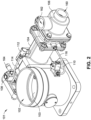
FIG. 2 is an isometric back view of the pneumatic inlet/blowdown valve assembly shown inFIG. 1 in accordance with example embodiments of the present disclosure. -
FIG. 3 is a cross-sectional view of the pneumatic inlet/blowdown valve assembly shown inFIG. 1 , wherein a dual-piston is in an idle condition, in accordance with example embodiments of the present disclosure. -
FIG. 4 is a cross-sectional view of the pneumatic inlet/blowdown valve assembly shown inFIG. 1 , wherein a dual-piston is in an actuated condition, in accordance with example embodiments of the present disclosure. -
FIG. 5 is a side cross-sectional view of the pneumatic inlet/blowdown valve assembly along line '5' ofFIG. 3 , illustrating a crank shaft connecting a piston shaft with a butterfly plate of the inlet valve. -
FIG. 6 is a schematic view of a compression system including a pneumatic inlet/blowdown valve assembly in accordance with example embodiments of the present disclosure. - Although the subject matter has been described in language specific to structural features and/or process operations, it is to be understood that the subject matter defined in the appended claims is not necessarily limited to the specific features or acts described above. Rather, the specific features and acts described above are disclosed as example forms of implementing the claims.
- Fluid compressors systems increase the pressure of a working fluid such as air or gas, and are widely used in a variety of industries such as in construction, manufacturing, agriculture, energy production, etc. Positive displacement compressor systems such as, but not limited to, rotary screw compressors, confine a successive volume of the working fluid within a closed space that is mechanically reduced, compressing the working fluid and increasing the working fluid's pressure and temperature. Types of rotary screw compressors include contact-cooled rotary (CCR) compressors, also called oil-injected rotary screw compressors, and oil-free rotary (OFR) compressors.
- In fluid compressor systems, capacity control is employed to regulate the capacity of the compressed working fluid, where the capacity of the fluid compressor system is the quantity of working fluid at which the fluid compressor system will operate at a specific discharge pressure. In rotary screw compressors, different capacity control schemes are used, including start/stop, load/unload, modulation, variable displacement, and variable speed. Load/unload (having a load operation and an unload operation) and modulation capacity control schemes are controlled through an inlet valve operating in synchrony with a blowdown valve.
- The use of pneumatic valves has benefits when compared to other types of valves such as hydraulic valves and diaphragm valves. For example, pneumatic valves may be less prone to leaking, are compact in size, and are easier to service as pneumatic lines can be vented directly to the atmosphere, whereas oil lines in hydraulic valves must be drained to a sump prior to any service operation. CCR compressors include a separation tank which stores compressed air that can be used as a source for actuation of pneumatic valves, including the inlet valve. A minimum pressure check valve (MPCV) maintains a minimum system pressure inside the separator tank. Using this minimum system pressure aids the pneumatic actuation of the inlet valve during a cold start or even when the system changes from an unload state to a load state. Thus, most inlet valves in CCR compressors are pneumatically operated.
- OFR compressor systems do not typically have a separation tank with minimum pressure check valve. Hence typically an OFR compressor systems do not have a minimum system pressure when starting from a cold start to actuate a pneumatic inlet valve. In OFR compressor systems, a second stage outlet is connected to the blowdown valve or unloader valve for the unloading operation or to start the OFR compressor systems with a minimum back pressure. The inlet valve and blowdown valve operations are synchronized in such a way that inlet valve will be in a closed condition (Normally Closed) and the blowdown valve will be in an open condition (Normally Open). OFR compressor systems may not develop a pressure buildup unless the blowdown valve is closed. Since both the inlet valve and blowdown valve operations are synchronized, finding a source of energy for closing the blowdown valve is necessary to provide a completely pneumatic inlet valve for an OFR compressor system.
- Accordingly, the present disclosure is directed to a fluid compressor system having a pneumatic inlet/blowdown valve assembly that utilizes a combination of pneumatic pressure and vacuum available in the fluid compressor system for the actuation of the inlet valve and the blowdown valve. The inlet valve is integrated with the blowdown valve, where their respective actuation is synchronized with the other.
- Referring generally to
FIGS. 1 through 6 , afluid compressor system 100 is shown. Thefluid compressor system 100 includes a first air-end 136, a second air-end 138, and a pneumatic inlet/blowdown valve assembly 101. Thefluid compressor system 100 may include amotor 140 driving the first air-end 136 and the second air-end 138. Thefirst airend 136 receives a compressible working fluid (e.g., air, gas, etc.) and compresses the working fluid in a first stage compression process. This compression also increases the temperature of the working fluid. - In example embodiments, the
fluid compressor system 100 includes afluid filter 134 disposed upstream from the pneumatic inlet/blowdown valve assembly 101 and the first air-end 136. Thefluid filter 134 may filter particles from the working fluid and prevents particulate matter from entering thefluid compressor system 100. - In example embodiments, the
fluid compressor system 100 includes anintercooler 142 to cool down the working fluid delivered by the first air-end 136 and aninterstage moisture separator 144 to separate moisture from the working fluid prior to entering the second air-end 138. An interstageblowdown solenoid valve 146 may be coupled between theinterstage moisture separator 144 and the second air-end 138 to vent an interstage pressure. In example embodiments (not shown), thefluid compressor system 100 may include an interstage venturi, also called a first stage venturi, coupled downstream from the first air-end 136 and upstream from the second air-end 138 to reduce pulsations within the compressed working fluid delivered by the first air-end 136. - The second air-
end 138 receives the working fluid delivered by theinterstage moisture separator 144 and further compresses it. In example embodiments, thefluid compressor system 100 also includes adischarge venturi 150, also called a second stage venturi, to reduce pulsations in the compressed fluid discharged from second stage compression process occurring in the second air-end 138. After passing through thedischarge venturi 150, the working fluid may flow through adischarge check valve 152, an after cooler 154, and a secondstage moisture separator 156, prior to exiting thefluid compressor system 100 for delivery. - In the example embodiment shown in
FIGS. 1 through 5 , the pneumatic inlet/blowdown assembly 101 includes aninlet valve 102, ablowdown valve 106, apistoncylinder actuator 104, afirst solenoid valve 110, and asecond solenoid valve 112. Theinlet valve 102 receives the working fluid entering thefluid compressor system 100 and regulates flow of the working fluid before it enters the first air-end 136. In example embodiments, theinlet valve 102 includes abutterfly plate 103. Thebutterfly plate 103 rotates between an open position and a closed position to respectively allow or block working fluid through theinlet valve 102. - A
blowdown valve inlet 160 of theblowdown valve 106 is coupled to thedischarge venturi 150 at the discharge of the second air-end 138. Theblowdown valve 106 is configured to release the buildup pressure within thefluid compressor system 100 through ablowdown valve outlet 162 when thefluid compressor system 100 is in the unloading operation and theblowdown valve 106 is open. In example embodiments, theblowdown valve outlet 162 is coupled to ablowdown muffler 148 to reduce noise and/or a blowdown diffuser (not shown) to distribute the exhausting hot compressed working fluid. - The piston-
cylinder actuator 104, as shown inFIGS. 3 and4 , is mechanically coupled to theinlet valve 102 and theblowdown valve 106. The piston-cylinder actuator 106 includes afirst piston 132 housed within afirst cylinder chamber 133, and asecond piston 134 housed within asecond cylinder chamber 135. Thefirst cylinder chamber 133 has a firstcylinder chamber end 133A and a secondcylinder chamber end 133B. Likewise, thesecond cylinder chamber 135 has a firstcylinder chamber end 135A and a secondcylinder chamber end 135B. In example embodiments, thefirst piston 132 and thesecond piston 134 are axially connected by apiston shaft 122 having anaxis 122A. Thepiston shaft 122 slides within the piston-cylinder actuator 104 in a linear motion along theaxis 122A, supported byguide bearings 123. - The
first cylinder chamber 133 defines a first chamber C1 between a first side of thefirst piston 132A and the firstcylinder chamber end 133A and a second chamber C2 between a second side of thefirst piston 132B and the secondcylinder chamber end 133B. Thesecond cylinder chamber 135 defines a third chamber C3 between a first side of thesecond piston 134A and the firstcylinder chamber end 135A. Thesecond cylinder chamber 135 defines a fourth chamber C4 between a second side of thesecond piston 134B and the secondcylinder chamber end 135B. - The
first piston 132 and thesecond piston 134 include at least onepiston seal 131 disposed around an outer circumference of each respective piston. The at least onepiston seal 131 prevents the escape of air from thefirst cylinder chamber 133, between the first chamber C1 and the second chamber C2, and thesecond cylinder chamber 135, between the third chamber C3 and the fourth chamber C4. In the example embodiment shown inFIGS. 3 and4 , the piston seals 131 are V-ring seals. In other example embodiments, the piston seals 131 may be U-rings, O-rings, flat seals, lip seals, guide rings, among others. The ring seals may be composed from Polytetrafluoroethylene (PTFE), nitrile, neoprene, ethylene propylene diene monomer (EPDM) rubber, a fluorocarbon rubber, or a combination thereof. - In example embodiments, a
compression spring 126 is disposed within the fourth chamber C4, where thecompression spring 126 is in contact with thesecond side 134B of thesecond piston 134 and secondcylinder chamber end 135B of thesecond cylinder chamber 135. Thecompression spring 126 biases thesecond piston 134 in a first direction away from the secondcylinder chamber end 135B of thesecond cylinder chamber 135, and towards the firstcylinder chamber end 135A of thesecond cylinder chamber 135. - In embodiments, the piston-
cylinder actuator 104 includes spring supports 127A and 127B.Spring support 127A is defined on the second side of thesecond piston 134B.Spring support 127B is defined on thesecond end 135B of thesecond cylinder chamber 135. Spring guides 127A and127B guide spring 126, keeping it in a position concentric with thepiston shaft 122, and attached to thesecond cylinder chamber 135 and thesecond piston 134. - The pneumatic inlet/
blowdown valve assembly 101 includes a slider crank 124 disposed within a slider crankchamber 120. The piston-cylinder actuator 104 defines the slider crankchamber 120 between thefirst cylinder chamber 133 and thesecond cylinder chamber 135. The slider crank 124 is coupled on one end to thebutterfly plate 103 of theinlet valve 102 and on a second end to thepiston shaft 122. The slider crank 124 opens and closes thebutterfly plate 103 of theinlet valve 102 depending on the position of thepiston shaft 122. As thepiston shaft 122 moves from the idle state to the actuated state, thebutterfly plate 103 is rotated within theinlet valve 102, between a closed position, to an open position, respectively. The pneumatic inlet/blowdown valve assembly 101 also includes a blowdownvalve piston cap 130 disposed within theblowdown valve 106 and coupled to thepiston shaft 122. The blowdownvalve piston cap 130 is configured to open and close theblowdown valve 106 through theblowdown valve inlet 160. As thepiston shaft 122 moves from the idle state to the actuated state, theblowdown piston cap 130 is actuated within the blowdown valve 10, between an open position, to a closed position, respectively. - During operation of the inlet/
blowdown valve assembly 101, thefirst piston 132 and thesecond piston 134 are configured to be actuated between an idle state and an actuated state. In the idle state, shown inFIG. 3 , theinlet valve 102 is closed to stop the flow of the working fluid into the first air-end 136 and theblowdown valve inlet 160 of theblowdown valve 106 is open to depressurize thefluid compressor system 100 through theblowdown valve outlet 162. In the actuated state, shown inFIG. 4 , theinlet valve 102 is open to allow the flow of the working fluid into the first air-end 136 and theblowdown valve inlet 160 is closed to allow a pressure buildup in thefluid compressor system 100. - In example embodiments, the
fluid compressor system 100 is operated between an unload state and a load state by controlling electrical signals to energize and actuate thefirst solenoid valve 110 and the second solenoid valve 108 (not shown). Thefluid compressor system 100 may remain in the unload state (or idle state) when thefirst solenoid valve 110 and thesecond solenoid valve 108 are in a de-energized state. In embodiments, both thefirst solenoid valve 110 and thesecond solenoid valve 108 are energized together to change the state of thefluid compressor system 100 to the load state. In other embodiments, thefirst solenoid valve 110 and thesecond solenoid valve 108 are energized asynchronously. - The
first solenoid valve 110 of the pneumatic inlet/blowdown valve assembly 101 is connected between thebutterfly plate 103 and the first air-end 136 and is connected to the fourth chamber C4 via a first connectingtube 116 as shown inFIG. 2 . At the start of the loading operation, the pneumatic inlet/blowdown valve assembly 101 is in the idle state, with thebutterfly plate 103 of theinlet valve 102 closed. As themotor 140 is energized and reaches a maximum speed, a first stage vacuum pressure is built below thebutterfly plate 103 and upstream of the first air-end 136. Thefirst solenoid valve 110 is energized, allowing the first stage vacuum pressure to flow into the fourth chamber C4 of thepiston cylinder actuator 104. - As the first stage vacuum is supplied to the fourth chamber C4, the
compression spring 126 is compressed, pulling thesecond piston 134 towards the secondcylinder chamber end 135B of thesecond cylinder chamber 135. Thus, thepiston shaft 122 moves the blowdownvalve piston cap 130, thefirst piston 132, thesecond piston 134, and the slider crank 124 into the actuated position. The blowdownvalve piston cap 130 closes theblowdown valve inlet 160, allowing the pressure within thefluid compressor system 100 to increase. The slider crank 124 simultaneously rotates thebutterfly plate 103, opening theinlet valve 102 to allow the working fluid to flow into the first air-end 136, thereby compressing the working fluid and supplying an interstage pressure. - As the
butterfly plate 103 completely opens, the first stage vacuum is supplied at a reduced amount into the fourth chamber C4. The actuated state of the piston-cylinder actuator 104 is maintained through the interstage pressure that the first air-end 136 supplies. In example embodiments, an interstage pressure tap 'B' is provided between theinterstage moisture separator 144 and the second air-end 138. In other embodiments, the pressure tap 'B' is provided between the first air-end 136 and the second air-end 138. The interstage pressure is supplied to the first chamber C1 and the third chamber C3 via aninline check valve 164 mounted to an inlet port of thesecond solenoid valve 108 and further through thequick exhaust valve 112, passing throughchannel 113. The pressure buildup in the first chamber C1 and the third chamber C3 aid thefirst piston 132 and thesecond piston 134 to maintain the actuated position of the secondcylinder chamber end 133B of thefirst cylinder chamber 133 and the secondcylinder chamber end 135B of thesecond cylinder chamber 135, respectively. Thesecond piston 134 holds thecompression spring 126 in a compressed position while thefluid compressor system 100 is loading, as shown in the example embodiment ofFIG. 4 . - In example embodiments, an
inline check valve 164 is coupled between the interstage pressure tap 'B' and thesecond solenoid valve 108 to restrict interstage vacuum action on the first chamber C1 and the third chamber C3 during startup of thefluid compressor system 100 or when thefluid compressor system 100 changes from the unloading operation to the loading operation. - In example embodiments, the pneumatic inlet/
blowdown valve assembly 101 further includes aquick exhaust valve 112 connected between thesecond solenoid valve 108 and the first chamber C1 and third chamber C3 via a second connectingtube 114. When thefluid compressor system 100 is set to the unloading operation, thesecond solenoid valve 108 is de-energized and thequick exhaust valve 112 rapidly vents the pressure buildup in the first chamber C1 and the third chamber C3, allowing thecompression spring 126 to pushsecond piston 134 along with thepiston shaft 122 back to the idle state shown inFIG. 3 , where theinlet valve 102 is closed and theblowdown valve 106 is open to vent the pressure buildup of thefluid compressor system 100 through a second stage blowdown piping 'A'. - In example embodiments, the piston-cylinder actuator includes a
vacuum setting screw 128 to manually adjust an unload vacuum for different package combinations of thefluid compressor system 100. The linear adjustments set through thevacuum setting screw 128 pushes thepiston shaft 122 forward in steps, moving the slider crank 124 which is coupled on the one end to thebutterfly plate 103. The setting of the vacuum setting screw may adjust the angular position of thebutterfly plate 103 in steps to maintain optimum clearance between thebutterfly plate 103 and a housing of theinlet valve 102 housing. - In example embodiments, the interstage pressure supplied to the first chamber C1 and the third chamber C3 via the
second solenoid valve 108 to keep theblowdown valve 106 closed and thecompression spring 126 compressed. In such embodiments, a larger piston-cylinder area may be used to balance the frictional forces on thefirst piston 132 and thesecond piston 134 to remain in the actuated state. Depending on the interstage pressure available, additional pistons (not shown) employing similar cylinder chamber arrangements may be disposed in the piston-cylinder actuator 104. In example embodiments, the size of thecompression spring 126 is selected based on the size of thesecond cylinder chamber 135, so as thesecond piston 134 retracts sufficiently (e.g., completely) during the unload operation. - In other example embodiments (not shown), the pneumatic inlet/
blowdown valve assembly 101 includes a vacuum-assisted spring return mechanism. In such embodiments, thesecond solenoid valve 108 includes a relief line that is connected back to the first stage vacuum pressure for quickly returning the pneumatic inlet/blowdown valve assembly to its idle state, wherein thecompression spring 126 biases the blowdownvalve piston cap 130 to open theblowdown valve 106. - In example embodiments, the
fluid compressor system 100 is an oil-free rotary (OFR) screw compressor. In other example embodiments (not shown), the fluid compressor system may be a contact-cooled rotary CCR screw compressor, a rotary vane compressor, a reciprocating compressor, a centrifugal compressor or an axial compressor. In other example embodiments, the pneumatic inlet-blowdown valve assembly 101 maybe incorporated or retrofitted with other equipment having a compression application, including but not limited to, heating, ventilation, and air conditioning (HVAC) systems, refrigeration systems, gas turbine systems, and so forth. - While the subject matter has been illustrated and described in detail in the drawings and foregoing description, the same is to be considered as illustrative and not restrictive in character, it being understood that only the preferred embodiments have been shown and described and that all changes and modifications that come within the scope of the appended claims are desired to be protected. It should be understood that while the use of words such as preferable, preferably, preferred or more preferred utilized in the description above indicate that the feature so described may be more desirable, it nonetheless may not be necessary and embodiments lacking the same may be contemplated as within the scope of the subject matter, the scope being defined by the claims that follow. In reading the claims, it is intended that when words such as "a," "an," "at least one," or "at least one portion" are used there is no intention to limit the claim to only one item unless specifically stated to the contrary in the claim. When the language "at least a portion" and/or "a portion" is used the item can include a portion and/or the entire item unless specifically stated to the contrary. Unless specified or limited otherwise, the terms "mounted," "connected," "supported," and "coupled" and variations thereof are used broadly and encompass both direct and indirect mountings, connections, supports, and couplings. Further, "connected" and "coupled" are not restricted to physical or mechanical connections or couplings.
Claims (10)
- A pneumatic inlet/blowdown valve assembly (101) for a fluid compressor system (100), comprising:an inlet valve (102) wherein a working fluid enters the fluid compressor system (100), the inlet valve regulating a flow of the working fluid into a first air-end (136) of the fluid compressor system,a blowdown valve (106) couplable to a discharge of a second air-end (138) of the fluid compressor system (100), the blowdown valve configured to release a pressure within the fluid compressor system,and a piston-cylinder actuator (104) in communication with the inlet valve (102) and the blowdown valve (106), the piston-cylinder actuator including:a first piston (132) housed within a first cylinder (133),a second piston (134) housed within a second cylinder (135), the first piston (132) and the second piston axially connected by a piston shaft (122), the first cylinder (133) defining a first chamber (C1) at a first side (132A) of the first piston and a second chamber (C2) at a second side (132B) of the first piston and the second cylinder defining a third chamber (C3) at a first side (134A) of the second piston and a fourth chamber (C4) at a second side (134B) of the second piston,a compression spring (126) disposed within the fourth chamber (C4),and the first piston (132) and the second piston (134) configured to be actuated between an idle state wherein the inlet valve (102) is closed to stop the flow of the working fluid into the fluid compressor system (100) and the blowdown valve (106) is open to depressurize the fluid compressor system, and an actuated state wherein the inlet valve is open to allow the flow of the working fluid into the first air-end (136) and the blowdown valve is closed to allow a pressure buildup in the fluid compressor system.
- The pneumatic inlet/blowdown valve assembly of claim 1, further including a blowdown valve piston cap (130) disposed within the blowdown valve (106), the blowdown valve piston cap coupled to the piston shaft (122) and configured to open and close the blowdown valve.
- The pneumatic inlet/blowdown valve assembly according to either preceding claim, further including a first solenoid valve (110) connectable between the inlet valve (102) and the first air-end (136), the first solenoid valve in communication with the fourth chamber (C4).
- The pneumatic inlet/blowdown valve assembly of claim 3, wherein the first solenoid valve (110) supplies a first stage vacuum pressure to the fourth chamber (C4) of the piston-cylinder actuator (104), the first stage vacuum pressure compressing the compression spring (126) and actuating the first piston (132) and the second piston (134) from the idle state to the actuated state.
- The pneumatic inlet/blowdown valve assembly of claim 4, further including a second solenoid valve (108) connectable to an interstage pressure tap (B) between the first air-end (136) and the second air-end (138), the second solenoid valve in communication with the first chamber (C1) and the third chamber (C3).
- The pneumatic inlet/blowdown valve assembly of claim 5, wherein the second solenoid valve (108) supplies an interstage pressure to the first chamber (C1) and the third chamber (C3) of the piston-cylinder actuator (104) when energized, the interstage pressure maintaining the first piston (132) and the second piston (134) at the actuated state while the fluid compressor system (100) is loading.
- The pneumatic inlet/blowdown valve assembly of claim 6, further including a quick exhaust valve (112) connected between the second solenoid valve (108) and the first chamber (C1) and third chamber (C3), wherein when the second solenoid valve is de-energized, the quick exhaust valve is configured to vent the pressure buildup in the first chamber and the third chamber, and the compression spring (126) pushes the first piston (132) and the second piston (134) to the idle state.
- The pneumatic inlet/blowdown valve assembly according to any one of the preceding claims, wherein the piston shaft (122) is mechanically coupled to a slider crank mechanism (124) that moves the inlet valve (102) between an open position and a closed position.
- A fluid compressor system (100) for compressing a working fluid comprising:a first air-end (136) operable to receive and compress the working fluid;a second air-end (138) operable to receive the working fluid from the first air-end (136) and further compress the working fluid;and a pneumatic inlet/blowdown valve assembly (101) according to any one of the preceding claims.
- The fluid compressor system according claim 9, wherein the fluid compressor system (100) is an oil-free rotary (OFR) compressor.
Applications Claiming Priority (1)
| Application Number | Priority Date | Filing Date | Title |
|---|---|---|---|
| US17/860,499 US11841718B1 (en) | 2022-07-08 | 2022-07-08 | Pneumatic inlet/blowdown valve assembly |
Publications (2)
| Publication Number | Publication Date |
|---|---|
| EP4303443A1 EP4303443A1 (en) | 2024-01-10 |
| EP4303443B1 true EP4303443B1 (en) | 2025-01-15 |
Family
ID=87060156
Family Applications (1)
| Application Number | Title | Priority Date | Filing Date |
|---|---|---|---|
| EP23182531.6A Active EP4303443B1 (en) | 2022-07-08 | 2023-06-29 | Pneumatic inlet/blowdown valve assembly |
Country Status (3)
| Country | Link |
|---|---|
| US (2) | US11841718B1 (en) |
| EP (1) | EP4303443B1 (en) |
| CN (1) | CN117365912B (en) |
Families Citing this family (3)
| Publication number | Priority date | Publication date | Assignee | Title |
|---|---|---|---|---|
| US11841718B1 (en) * | 2022-07-08 | 2023-12-12 | Ingersoll-Rand Industrial U.S., Inc. | Pneumatic inlet/blowdown valve assembly |
| US20250154877A1 (en) * | 2023-11-15 | 2025-05-15 | Rtx Corporation | Slider seal of gas turbine engine |
| CN121025740B (en) * | 2025-09-04 | 2026-06-16 | 开封市鑫联空分设备有限公司 | A wastewater discharge device for an air separation unit |
Family Cites Families (16)
| Publication number | Priority date | Publication date | Assignee | Title |
|---|---|---|---|---|
| US3367562A (en) | 1966-06-23 | 1968-02-06 | Atlas Copco Ab | Means for unloading and controlling compressor units |
| US4068980A (en) | 1976-10-01 | 1978-01-17 | Gardner-Denver Company | Compressor startup control |
| US4335582A (en) | 1981-02-20 | 1982-06-22 | Dunham-Bush, Inc. | Unloading control system for helical screw compressor refrigeration system |
| EP0130662B1 (en) | 1983-04-08 | 1988-06-29 | Cash Engineering Co. Pty. Limited | Compressor control system |
| JPH0739828B2 (en) | 1986-09-01 | 1995-05-01 | 株式会社日立製作所 | Capacity control device for multi-stage compressor |
| US4934652A (en) * | 1989-12-11 | 1990-06-19 | Otis Engineering Corporation | Dual stage valve actuator |
| US5044894A (en) * | 1990-11-30 | 1991-09-03 | Carrier Corporation | Capacity volume ratio control for twin screw compressors |
| US5924672A (en) * | 1995-03-13 | 1999-07-20 | Provacon, Inc. | Valve and actuator in combination |
| US6026587A (en) | 1998-07-10 | 2000-02-22 | Westinghouse Air Brake Company | Intercooler blowdown valve |
| BE1015079A4 (en) | 2002-08-22 | 2004-09-07 | Atlas Copco Airpower Nv | Compressor with pressure relief. |
| WO2006093821A1 (en) | 2005-02-26 | 2006-09-08 | Ingersoll-Rand Company | System and method for controlling a variable speed compressor during stopping |
| AU2007292454B2 (en) | 2006-09-05 | 2013-07-18 | New York Air Brake Llc | Oil-free air compressor system with inlet throttle |
| US8397743B2 (en) * | 2010-11-08 | 2013-03-19 | Emerson Process Management Regulator Technologies, Inc. | Internal relief valve apparatus for use with fluid regulators |
| US10072682B2 (en) * | 2015-07-07 | 2018-09-11 | Ge Oil & Gas Pressure Control Lp | Multi-chamber diaphragm actuator with synchronized supply system |
| WO2018234910A1 (en) * | 2017-06-21 | 2018-12-27 | Atlas Copco Airpower, Naamloze Vennootschap | INTAKE VALVE FOR THE INPUT OF A COMPRESSOR ELEMENT AND COMPRESSOR AND COMPRESSOR ELEMENT EQUIPPED WITH SUCH AN INTAKE VALVE |
| US11841718B1 (en) * | 2022-07-08 | 2023-12-12 | Ingersoll-Rand Industrial U.S., Inc. | Pneumatic inlet/blowdown valve assembly |
-
2022
- 2022-07-08 US US17/860,499 patent/US11841718B1/en active Active
-
2023
- 2023-06-29 EP EP23182531.6A patent/EP4303443B1/en active Active
- 2023-07-05 CN CN202310816621.6A patent/CN117365912B/en active Active
- 2023-11-02 US US18/500,609 patent/US12468321B2/en active Active
Also Published As
| Publication number | Publication date |
|---|---|
| EP4303443A1 (en) | 2024-01-10 |
| US11841718B1 (en) | 2023-12-12 |
| CN117365912A (en) | 2024-01-09 |
| US20240061454A1 (en) | 2024-02-22 |
| CN117365912B (en) | 2026-06-19 |
| US12468321B2 (en) | 2025-11-11 |
Similar Documents
| Publication | Publication Date | Title |
|---|---|---|
| EP4303443A1 (en) | Pneumatic inlet/blowdown valve assembly | |
| CN109931259B (en) | Variable volume ratio compressor | |
| CN100334352C (en) | Diagnostic system of compressor | |
| EP0177234A2 (en) | Refrigeration system | |
| US4611976A (en) | Capacity and internal compression control device in a screw compressor | |
| JP5697022B2 (en) | Variable capacity compressor | |
| CN1896519A (en) | Compound compressors | |
| CN100436824C (en) | Screw compressors with axial motion control | |
| EP3674553B1 (en) | Variable volume ratio screw compressor | |
| AU2007292454B2 (en) | Oil-free air compressor system with inlet throttle | |
| US11994232B1 (en) | Electro-magnetic throttle valve with integrated blowdown conduit | |
| US6881040B2 (en) | Multi-stage screw compressor unit accommodating high suction pressure and pressure fluctuations and method of operation thereof | |
| KR101012946B1 (en) | Multistage gas compression device | |
| WO2015021117A1 (en) | Variable capacity reciprocating compressor | |
| JP5123715B2 (en) | Swash plate compressor | |
| US20100272580A1 (en) | Slide valve with hot gas bypass port | |
| CN110939557B (en) | Compressor flow regulating mechanism and method | |
| WO2010116388A1 (en) | Screw compressor specially suitable to be connected in parallel in compression units | |
| CN223330795U (en) | Screw compressors and air conditioners | |
| EP4118367A1 (en) | Valve for a vacuum apparatus | |
| KR102138568B1 (en) | Compressor | |
| CN110410328A (en) | Compressor and air conditioning system with automatically regulated slide valve position | |
| CN216111191U (en) | Air inlet valve and oil-free air compressor | |
| CN119594020A (en) | Screw compressor and air conditioner | |
| KR20160119120A (en) | Corrosion resistant pneumatic actuator |
Legal Events
| Date | Code | Title | Description |
|---|---|---|---|
| PUAI | Public reference made under article 153(3) epc to a published international application that has entered the european phase |
Free format text: ORIGINAL CODE: 0009012 |
|
| STAA | Information on the status of an ep patent application or granted ep patent |
Free format text: STATUS: THE APPLICATION HAS BEEN PUBLISHED |
|
| AK | Designated contracting states |
Kind code of ref document: A1 Designated state(s): AL AT BE BG CH CY CZ DE DK EE ES FI FR GB GR HR HU IE IS IT LI LT LU LV MC ME MK MT NL NO PL PT RO RS SE SI SK SM TR |
|
| STAA | Information on the status of an ep patent application or granted ep patent |
Free format text: STATUS: REQUEST FOR EXAMINATION WAS MADE |
|
| 17P | Request for examination filed |
Effective date: 20240320 |
|
| RBV | Designated contracting states (corrected) |
Designated state(s): AL AT BE BG CH CY CZ DE DK EE ES FI FR GB GR HR HU IE IS IT LI LT LU LV MC ME MK MT NL NO PL PT RO RS SE SI SK SM TR |
|
| GRAP | Despatch of communication of intention to grant a patent |
Free format text: ORIGINAL CODE: EPIDOSNIGR1 |
|
| STAA | Information on the status of an ep patent application or granted ep patent |
Free format text: STATUS: GRANT OF PATENT IS INTENDED |
|
| RIC1 | Information provided on ipc code assigned before grant |
Ipc: F04C 29/12 20060101ALI20240725BHEP Ipc: F04D 27/00 20060101ALI20240725BHEP Ipc: F04C 28/06 20060101ALI20240725BHEP Ipc: F04C 23/00 20060101ALI20240725BHEP Ipc: F04C 18/16 20060101ALI20240725BHEP Ipc: F04C 14/06 20060101ALI20240725BHEP Ipc: F04B 41/06 20060101ALI20240725BHEP Ipc: F04B 25/00 20060101ALI20240725BHEP Ipc: F04B 39/08 20060101ALI20240725BHEP Ipc: F04B 49/22 20060101ALI20240725BHEP Ipc: F04B 49/03 20060101AFI20240725BHEP |
|
| INTG | Intention to grant announced |
Effective date: 20240805 |
|
| GRAS | Grant fee paid |
Free format text: ORIGINAL CODE: EPIDOSNIGR3 |
|
| GRAA | (expected) grant |
Free format text: ORIGINAL CODE: 0009210 |
|
| STAA | Information on the status of an ep patent application or granted ep patent |
Free format text: STATUS: THE PATENT HAS BEEN GRANTED |
|
| AK | Designated contracting states |
Kind code of ref document: B1 Designated state(s): AL AT BE BG CH CY CZ DE DK EE ES FI FR GB GR HR HU IE IS IT LI LT LU LV MC ME MK MT NL NO PL PT RO RS SE SI SK SM TR |
|
| REG | Reference to a national code |
Ref country code: CH Ref legal event code: EP Ref country code: GB Ref legal event code: FG4D |
|
| REG | Reference to a national code |
Ref country code: DE Ref legal event code: R096 Ref document number: 602023001663 Country of ref document: DE |
|
| REG | Reference to a national code |
Ref country code: IE Ref legal event code: FG4D |
|
| REG | Reference to a national code |
Ref country code: NL Ref legal event code: MP Effective date: 20250115 |
|
| PG25 | Lapsed in a contracting state [announced via postgrant information from national office to epo] |
Ref country code: NL Free format text: LAPSE BECAUSE OF FAILURE TO SUBMIT A TRANSLATION OF THE DESCRIPTION OR TO PAY THE FEE WITHIN THE PRESCRIBED TIME-LIMIT Effective date: 20250115 |
|
| PG25 | Lapsed in a contracting state [announced via postgrant information from national office to epo] |
Ref country code: RS Free format text: LAPSE BECAUSE OF FAILURE TO SUBMIT A TRANSLATION OF THE DESCRIPTION OR TO PAY THE FEE WITHIN THE PRESCRIBED TIME-LIMIT Effective date: 20250415 |
|
| PG25 | Lapsed in a contracting state [announced via postgrant information from national office to epo] |
Ref country code: FI Free format text: LAPSE BECAUSE OF FAILURE TO SUBMIT A TRANSLATION OF THE DESCRIPTION OR TO PAY THE FEE WITHIN THE PRESCRIBED TIME-LIMIT Effective date: 20250115 |
|
| PG25 | Lapsed in a contracting state [announced via postgrant information from national office to epo] |
Ref country code: PL Free format text: LAPSE BECAUSE OF FAILURE TO SUBMIT A TRANSLATION OF THE DESCRIPTION OR TO PAY THE FEE WITHIN THE PRESCRIBED TIME-LIMIT Effective date: 20250115 |
|
| PG25 | Lapsed in a contracting state [announced via postgrant information from national office to epo] |
Ref country code: ES Free format text: LAPSE BECAUSE OF FAILURE TO SUBMIT A TRANSLATION OF THE DESCRIPTION OR TO PAY THE FEE WITHIN THE PRESCRIBED TIME-LIMIT Effective date: 20250115 |
|
| REG | Reference to a national code |
Ref country code: LT Ref legal event code: MG9D |
|
| PG25 | Lapsed in a contracting state [announced via postgrant information from national office to epo] |
Ref country code: NO Free format text: LAPSE BECAUSE OF FAILURE TO SUBMIT A TRANSLATION OF THE DESCRIPTION OR TO PAY THE FEE WITHIN THE PRESCRIBED TIME-LIMIT Effective date: 20250415 Ref country code: IS Free format text: LAPSE BECAUSE OF FAILURE TO SUBMIT A TRANSLATION OF THE DESCRIPTION OR TO PAY THE FEE WITHIN THE PRESCRIBED TIME-LIMIT Effective date: 20250515 |
|
| REG | Reference to a national code |
Ref country code: AT Ref legal event code: MK05 Ref document number: 1759994 Country of ref document: AT Kind code of ref document: T Effective date: 20250115 |
|
| PG25 | Lapsed in a contracting state [announced via postgrant information from national office to epo] |
Ref country code: HR Free format text: LAPSE BECAUSE OF FAILURE TO SUBMIT A TRANSLATION OF THE DESCRIPTION OR TO PAY THE FEE WITHIN THE PRESCRIBED TIME-LIMIT Effective date: 20250115 |
|
| PG25 | Lapsed in a contracting state [announced via postgrant information from national office to epo] |
Ref country code: LV Free format text: LAPSE BECAUSE OF FAILURE TO SUBMIT A TRANSLATION OF THE DESCRIPTION OR TO PAY THE FEE WITHIN THE PRESCRIBED TIME-LIMIT Effective date: 20250115 Ref country code: PT Free format text: LAPSE BECAUSE OF FAILURE TO SUBMIT A TRANSLATION OF THE DESCRIPTION OR TO PAY THE FEE WITHIN THE PRESCRIBED TIME-LIMIT Effective date: 20250515 |
|
| PG25 | Lapsed in a contracting state [announced via postgrant information from national office to epo] |
Ref country code: GR Free format text: LAPSE BECAUSE OF FAILURE TO SUBMIT A TRANSLATION OF THE DESCRIPTION OR TO PAY THE FEE WITHIN THE PRESCRIBED TIME-LIMIT Effective date: 20250416 Ref country code: BG Free format text: LAPSE BECAUSE OF FAILURE TO SUBMIT A TRANSLATION OF THE DESCRIPTION OR TO PAY THE FEE WITHIN THE PRESCRIBED TIME-LIMIT Effective date: 20250115 |
|
| PG25 | Lapsed in a contracting state [announced via postgrant information from national office to epo] |
Ref country code: AT Free format text: LAPSE BECAUSE OF FAILURE TO SUBMIT A TRANSLATION OF THE DESCRIPTION OR TO PAY THE FEE WITHIN THE PRESCRIBED TIME-LIMIT Effective date: 20250115 |
|
| PG25 | Lapsed in a contracting state [announced via postgrant information from national office to epo] |
Ref country code: SE Free format text: LAPSE BECAUSE OF FAILURE TO SUBMIT A TRANSLATION OF THE DESCRIPTION OR TO PAY THE FEE WITHIN THE PRESCRIBED TIME-LIMIT Effective date: 20250115 |
|
| PG25 | Lapsed in a contracting state [announced via postgrant information from national office to epo] |
Ref country code: SM Free format text: LAPSE BECAUSE OF FAILURE TO SUBMIT A TRANSLATION OF THE DESCRIPTION OR TO PAY THE FEE WITHIN THE PRESCRIBED TIME-LIMIT Effective date: 20250115 |
|
| PG25 | Lapsed in a contracting state [announced via postgrant information from national office to epo] |
Ref country code: DK Free format text: LAPSE BECAUSE OF FAILURE TO SUBMIT A TRANSLATION OF THE DESCRIPTION OR TO PAY THE FEE WITHIN THE PRESCRIBED TIME-LIMIT Effective date: 20250115 |
|
| PGFP | Annual fee paid to national office [announced via postgrant information from national office to epo] |
Ref country code: DE Payment date: 20250630 Year of fee payment: 3 |
|
| PGFP | Annual fee paid to national office [announced via postgrant information from national office to epo] |
Ref country code: IT Payment date: 20250630 Year of fee payment: 3 |
|
| REG | Reference to a national code |
Ref country code: DE Ref legal event code: R097 Ref document number: 602023001663 Country of ref document: DE |
|
| PG25 | Lapsed in a contracting state [announced via postgrant information from national office to epo] |
Ref country code: EE Free format text: LAPSE BECAUSE OF FAILURE TO SUBMIT A TRANSLATION OF THE DESCRIPTION OR TO PAY THE FEE WITHIN THE PRESCRIBED TIME-LIMIT Effective date: 20250115 Ref country code: CZ Free format text: LAPSE BECAUSE OF FAILURE TO SUBMIT A TRANSLATION OF THE DESCRIPTION OR TO PAY THE FEE WITHIN THE PRESCRIBED TIME-LIMIT Effective date: 20250115 |
|
| PG25 | Lapsed in a contracting state [announced via postgrant information from national office to epo] |
Ref country code: RO Free format text: LAPSE BECAUSE OF FAILURE TO SUBMIT A TRANSLATION OF THE DESCRIPTION OR TO PAY THE FEE WITHIN THE PRESCRIBED TIME-LIMIT Effective date: 20250115 |
|
| PG25 | Lapsed in a contracting state [announced via postgrant information from national office to epo] |
Ref country code: SK Free format text: LAPSE BECAUSE OF FAILURE TO SUBMIT A TRANSLATION OF THE DESCRIPTION OR TO PAY THE FEE WITHIN THE PRESCRIBED TIME-LIMIT Effective date: 20250115 |
|
| PLBE | No opposition filed within time limit |
Free format text: ORIGINAL CODE: 0009261 |
|
| STAA | Information on the status of an ep patent application or granted ep patent |
Free format text: STATUS: NO OPPOSITION FILED WITHIN TIME LIMIT |
|
| 26N | No opposition filed |
Effective date: 20251016 |
|
| PG25 | Lapsed in a contracting state [announced via postgrant information from national office to epo] |
Ref country code: MC Free format text: LAPSE BECAUSE OF FAILURE TO SUBMIT A TRANSLATION OF THE DESCRIPTION OR TO PAY THE FEE WITHIN THE PRESCRIBED TIME-LIMIT Effective date: 20250115 |
|
| PG25 | Lapsed in a contracting state [announced via postgrant information from national office to epo] |
Ref country code: LU Free format text: LAPSE BECAUSE OF NON-PAYMENT OF DUE FEES Effective date: 20250629 |
|
| REG | Reference to a national code |
Ref country code: BE Ref legal event code: MM Effective date: 20250630 |
|
| PG25 | Lapsed in a contracting state [announced via postgrant information from national office to epo] |
Ref country code: IE Free format text: LAPSE BECAUSE OF NON-PAYMENT OF DUE FEES Effective date: 20250629 |
|
| PG25 | Lapsed in a contracting state [announced via postgrant information from national office to epo] |
Ref country code: BE Free format text: LAPSE BECAUSE OF NON-PAYMENT OF DUE FEES Effective date: 20250630 |
|
| PG25 | Lapsed in a contracting state [announced via postgrant information from national office to epo] |
Ref country code: LT Free format text: LAPSE BECAUSE OF FAILURE TO SUBMIT A TRANSLATION OF THE DESCRIPTION OR TO PAY THE FEE WITHIN THE PRESCRIBED TIME-LIMIT Effective date: 20250115 |
|
| PGFP | Annual fee paid to national office [announced via postgrant information from national office to epo] |
Ref country code: FR Payment date: 20260625 Year of fee payment: 4 |
|
| PG25 | Lapsed in a contracting state [announced via postgrant information from national office to epo] |
Ref country code: CY Free format text: LAPSE BECAUSE OF FAILURE TO SUBMIT A TRANSLATION OF THE DESCRIPTION OR TO PAY THE FEE WITHIN THE PRESCRIBED TIME-LIMIT Effective date: 20250115 |