EP4303134A1 - Former, bagmaking and packaging machine, and method of manufacturing bagmaking and packaging machine - Google Patents
Former, bagmaking and packaging machine, and method of manufacturing bagmaking and packaging machine Download PDFInfo
- Publication number
- EP4303134A1 EP4303134A1 EP23175300.5A EP23175300A EP4303134A1 EP 4303134 A1 EP4303134 A1 EP 4303134A1 EP 23175300 A EP23175300 A EP 23175300A EP 4303134 A1 EP4303134 A1 EP 4303134A1
- Authority
- EP
- European Patent Office
- Prior art keywords
- bagmaking
- packaging machine
- former
- tube member
- packaging
- Prior art date
- Legal status (The legal status is an assumption and is not a legal conclusion. Google has not performed a legal analysis and makes no representation as to the accuracy of the status listed.)
- Pending
Links
Images



Classifications
-
- B—PERFORMING OPERATIONS; TRANSPORTING
- B65—CONVEYING; PACKING; STORING; HANDLING THIN OR FILAMENTARY MATERIAL
- B65B—MACHINES, APPARATUS OR DEVICES FOR, OR METHODS OF, PACKAGING ARTICLES OR MATERIALS; UNPACKING
- B65B9/00—Enclosing successive articles, or quantities of material, e.g. liquids or semiliquids, in flat, folded, or tubular webs of flexible sheet material; Subdividing filled flexible tubes to form packages
- B65B9/06—Enclosing successive articles, or quantities of material, in a longitudinally-folded web, or in a web folded into a tube about the articles or quantities of material placed upon it
- B65B9/08—Enclosing successive articles, or quantities of material, in a longitudinally-folded web, or in a web folded into a tube about the articles or quantities of material placed upon it in a web folded and sealed transversely to form pockets which are subsequently filled and then closed by sealing
-
- B—PERFORMING OPERATIONS; TRANSPORTING
- B65—CONVEYING; PACKING; STORING; HANDLING THIN OR FILAMENTARY MATERIAL
- B65B—MACHINES, APPARATUS OR DEVICES FOR, OR METHODS OF, PACKAGING ARTICLES OR MATERIALS; UNPACKING
- B65B9/00—Enclosing successive articles, or quantities of material, e.g. liquids or semiliquids, in flat, folded, or tubular webs of flexible sheet material; Subdividing filled flexible tubes to form packages
- B65B9/10—Enclosing successive articles, or quantities of material, in preformed tubular webs, or in webs formed into tubes around filling nozzles, e.g. extruded tubular webs
- B65B9/20—Enclosing successive articles, or quantities of material, in preformed tubular webs, or in webs formed into tubes around filling nozzles, e.g. extruded tubular webs the webs being formed into tubes in situ around the filling nozzles
- B65B9/22—Forming shoulders; Tube formers
-
- B—PERFORMING OPERATIONS; TRANSPORTING
- B65—CONVEYING; PACKING; STORING; HANDLING THIN OR FILAMENTARY MATERIAL
- B65B—MACHINES, APPARATUS OR DEVICES FOR, OR METHODS OF, PACKAGING ARTICLES OR MATERIALS; UNPACKING
- B65B39/00—Nozzles, funnels or guides for introducing articles or materials into containers or wrappers
- B65B39/007—Guides or funnels for introducing articles into containers or wrappers
-
- B—PERFORMING OPERATIONS; TRANSPORTING
- B65—CONVEYING; PACKING; STORING; HANDLING THIN OR FILAMENTARY MATERIAL
- B65B—MACHINES, APPARATUS OR DEVICES FOR, OR METHODS OF, PACKAGING ARTICLES OR MATERIALS; UNPACKING
- B65B41/00—Supplying or feeding container-forming sheets or wrapping material
- B65B41/12—Feeding webs from rolls
-
- B—PERFORMING OPERATIONS; TRANSPORTING
- B65—CONVEYING; PACKING; STORING; HANDLING THIN OR FILAMENTARY MATERIAL
- B65B—MACHINES, APPARATUS OR DEVICES FOR, OR METHODS OF, PACKAGING ARTICLES OR MATERIALS; UNPACKING
- B65B51/00—Devices for, or methods of, sealing or securing package folds or closures; Devices for gathering or twisting wrappers, or necks of bags
- B65B51/10—Applying or generating heat or pressure or combinations thereof
- B65B51/26—Devices specially adapted for producing transverse or longitudinal seams in webs or tubes
-
- B—PERFORMING OPERATIONS; TRANSPORTING
- B65—CONVEYING; PACKING; STORING; HANDLING THIN OR FILAMENTARY MATERIAL
- B65B—MACHINES, APPARATUS OR DEVICES FOR, OR METHODS OF, PACKAGING ARTICLES OR MATERIALS; UNPACKING
- B65B51/00—Devices for, or methods of, sealing or securing package folds or closures; Devices for gathering or twisting wrappers, or necks of bags
- B65B51/10—Applying or generating heat or pressure or combinations thereof
- B65B51/26—Devices specially adapted for producing transverse or longitudinal seams in webs or tubes
- B65B51/30—Devices, e.g. jaws, for applying pressure and heat, e.g. for subdividing filled tubes
-
- B—PERFORMING OPERATIONS; TRANSPORTING
- B65—CONVEYING; PACKING; STORING; HANDLING THIN OR FILAMENTARY MATERIAL
- B65B—MACHINES, APPARATUS OR DEVICES FOR, OR METHODS OF, PACKAGING ARTICLES OR MATERIALS; UNPACKING
- B65B59/00—Arrangements to enable machines to handle articles of different sizes, to produce packages of different sizes, to vary the contents of packages, to handle different types of packaging material, or to give access for cleaning or maintenance purposes
- B65B59/04—Machines constructed with readily-detachable units or assemblies, e.g. to facilitate maintenance
-
- B—PERFORMING OPERATIONS; TRANSPORTING
- B65—CONVEYING; PACKING; STORING; HANDLING THIN OR FILAMENTARY MATERIAL
- B65B—MACHINES, APPARATUS OR DEVICES FOR, OR METHODS OF, PACKAGING ARTICLES OR MATERIALS; UNPACKING
- B65B61/00—Auxiliary devices, not otherwise provided for, for operating on sheets, blanks, webs, binding material, containers or packages
- B65B61/04—Auxiliary devices, not otherwise provided for, for operating on sheets, blanks, webs, binding material, containers or packages for severing webs, or for separating joined packages
- B65B61/06—Auxiliary devices, not otherwise provided for, for operating on sheets, blanks, webs, binding material, containers or packages for severing webs, or for separating joined packages by cutting
-
- B—PERFORMING OPERATIONS; TRANSPORTING
- B65—CONVEYING; PACKING; STORING; HANDLING THIN OR FILAMENTARY MATERIAL
- B65B—MACHINES, APPARATUS OR DEVICES FOR, OR METHODS OF, PACKAGING ARTICLES OR MATERIALS; UNPACKING
- B65B9/00—Enclosing successive articles, or quantities of material, e.g. liquids or semiliquids, in flat, folded, or tubular webs of flexible sheet material; Subdividing filled flexible tubes to form packages
- B65B9/10—Enclosing successive articles, or quantities of material, in preformed tubular webs, or in webs formed into tubes around filling nozzles, e.g. extruded tubular webs
- B65B9/20—Enclosing successive articles, or quantities of material, in preformed tubular webs, or in webs formed into tubes around filling nozzles, e.g. extruded tubular webs the webs being formed into tubes in situ around the filling nozzles
-
- B—PERFORMING OPERATIONS; TRANSPORTING
- B65—CONVEYING; PACKING; STORING; HANDLING THIN OR FILAMENTARY MATERIAL
- B65B—MACHINES, APPARATUS OR DEVICES FOR, OR METHODS OF, PACKAGING ARTICLES OR MATERIALS; UNPACKING
- B65B9/00—Enclosing successive articles, or quantities of material, e.g. liquids or semiliquids, in flat, folded, or tubular webs of flexible sheet material; Subdividing filled flexible tubes to form packages
- B65B9/10—Enclosing successive articles, or quantities of material, in preformed tubular webs, or in webs formed into tubes around filling nozzles, e.g. extruded tubular webs
- B65B9/20—Enclosing successive articles, or quantities of material, in preformed tubular webs, or in webs formed into tubes around filling nozzles, e.g. extruded tubular webs the webs being formed into tubes in situ around the filling nozzles
- B65B9/2014—Tube advancing means
- B65B9/2028—Rollers or belts
Definitions
- the present invention relates to a former, a bagmaking and packaging machine, and a method of manufacturing a bagmaking and packaging machine.
- Patent Literature 1 Japanese Patent Unexamined Publication No. 2012-86874A discloses a former where a collar member (a sailor collar member) is connected to one end of a tube member. The former is used in a bagmaking and packaging machine together with a wraparound member around which a packaging material folded by the former is wrapped.
- the packaging material folded by the former needs to be formed in a cylindrical shape by the wraparound member without causing the packaging material to crease or become crooked. For this reason, high-precision positioning is required to assemble the former and the wraparound member.
- work is performed to secure the former and the wraparound member to a support member using welding or screws, for example, and thereafter to adjust their positions. Such assembly work including position adjustment is complicated.
- a former according to a first aspect folds and guides a packaging material.
- the former includes a collar member that guides the packaging material and a first tube member for forming in a tubular shape the packaging material guided by the collar member.
- the first tube member has one end to which the collar member is connected, and includes a first mating portion.
- a bagmaking and packaging machine forms a packaging material in a tubular shape and packages packaging articles.
- the bagmaking and packaging machine includes the aforementioned former, a wraparound member, and a support member. Around the wraparound member is wrapped the packaging material folded by the former. The support member supports the former and the wraparound member.
- the first mating portion is mated with the support member.
- the former In this bagmaking and packaging machine, the former is positioned on the support member by mating. Consequently, by the use of this bagmaking and packaging machine, the former is positioned with high precision by simple assembly work.
- a bagmaking and packaging machine is the bagmaking and packaging machine of the second aspect, wherein the wraparound member includes a second tube member and a chute.
- the second tube member is a tubular member around which the packaging material is wrapped.
- the chute is a member that guides the packaging articles to the second tube member.
- the chute is connected to one end of the second tube member and includes a second mating portion that is mated with the support member.
- the wraparound member is positioned on the support member by mating. Consequently, by the use of this bagmaking and packaging machine, the former and the wraparound member are positioned with high precision by simple assembly work.
- a bagmaking and packaging machine is the bagmaking and packaging machine of the third aspect, wherein the support member includes a first support member and a second support member.
- the first support member supports the former.
- the second support member supports the wraparound member.
- first support member In the first support member is formed a first mating hole with which the first mating portion is mated. In the second support member is formed a second mating hole with which the second mating portion is mated.
- a central axis of the first mating hole coincides with a central axis of the second mating hole.
- the central axis of the first mating hole coincides with the central axis of the second mating hole.
- the former and the wraparound member are mutually positioned as a result of the first mating portion being mated with the first mating hole and the second mating portion being mated with the second mating hole. Consequently, by the use of this bagmaking and packaging machine, the former and the wraparound member are positioned with high precision by simple assembly work.
- a bagmaking and packaging machine is any of the bagmaking and packaging machines of the second aspect to the fourth aspect, wherein a cutout portion of the first tube member to which is connected an edge of the collar member is formed across the circumferential direction in a surface on the one end side of the first tube member.
- the collar member is positioned by bringing the edge, which defines a notch, into abutment with the cutout portion. Consequently, by the use of this bagmaking and packaging machine, the collar member is positioned on the first tube member with high precision.
- a bagmaking and packaging machine is the bagmaking and packaging machine of the fifth aspect, wherein a depth of the cutout portion is greater than a plate thickness of the collar member.
- the depth of the cutout portion is formed greater than the plate thickness of the collar member, so an upper end surface of the first tube member is not even with the surface of the collar member.
- the upper end surface that is not even with the surface of the collar member can make contact with the packaging material that has slightly separated from the surface of the collar member, so the packaging material can be normally folded at the upper end of the first tube member. Consequently, by the use of this bagmaking and packaging machine, the occurrence of problems in the folding of the packaging material at the upper end of the first tube member is inhibited.
- a method of manufacturing a bagmaking and packaging machine is a method of manufacturing any of the bagmaking and packaging machines of the second aspect to the sixth aspect, including a step of connecting the collar member and the first tube member to each other and thereafter forming the first mating portion using cutting.
- the first mating portion is formed with high precision using cutting, so the former is positioned on the support member with high precision.
- a method of manufacturing a bagmaking and packaging machine is a method of manufacturing the bagmaking and packaging machine of the third aspect or the fourth aspect, including a step of forming the second mating portion using cutting.
- the second mating portion is formed with high precision using cutting, so the wraparound member is positioned on the support member with high precision.
- a method of manufacturing a bagmaking and packaging machine is a method of manufacturing the bagmaking and packaging machine of the third aspect or the fourth aspect, wherein the bagmaking and packaging machine further includes pull-down belts that convey the packaging material along a length direction of the second tube member.
- the method of manufacturing the bagmaking and packaging machine includes a step of connecting the second tube member and the chute to each other and thereafter forming first surfaces that oppose the pull-down belts in an outer peripheral surface of the second tube member using cutting.
- the first surfaces are formed with high precision using cutting.
- a method of manufacturing a bagmaking and packaging machine is a method of manufacturing the bagmaking and packaging machine of the third aspect or the fourth aspect, wherein the bagmaking and packaging machine further includes a longitudinal sealing mechanism that seals edges of the packaging material along a length direction of the second tube member.
- the method of manufacturing the bagmaking and packaging machine includes a step of connecting the second tube member and the chute to each other and thereafter forming a second surface that opposes the longitudinal sealing mechanism in an outer peripheral surface of the second tube member using cutting.
- the second surface is formed with high precision using cutting.
- a method of manufacturing a bagmaking and packaging machine is a method of manufacturing the bagmaking and packaging machine of the fifth aspect or the sixth aspect, including a step of forming the cutout portion using cutting.
- the cutout portion is formed with high precision using cutting. For this reason, deformation is inhibited from occurring in the edge of the collar member during connection to the cutout portion.
- the former is positioned with high precision by simple assembly work. Furthermore, by the use of the method of manufacturing the bagmaking and packaging machine, the former is positioned on the support member with high precision.
- a bagmaking and packaging machine 100 and a former 20 according to an embodiment of the present invention will be described below.
- the directions of up/down, right/left, and front/rear are defined as indicated by the arrows in the drawings.
- FIG. 1 is a perspective view of a packaging machine 1 including the bagmaking and packaging machine 100.
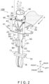
- FIG. 2 is a perspective view showing the schematic configuration of the bagmaking and packaging machine 100.
- the packaging machine 1 mainly includes a weighing machine 2 and the bagmaking and packaging machine 100.
- the weighing machine 2 weighs packaging articles A (i.e., articles that are to be packaged) put into bags B formed by the bagmaking and packaging machine 100 and drops the packaging articles A toward the bagmaking and packaging machine 100.
- the packaging articles A are not particularly limited; here, they are articles that are light in weight and large in size, such as potato chips.
- the bagmaking and packaging machine 100 receives the packaging articles A dropping from the weighing machine 2 and packages them in a packaging material F formed in a tubular shape (hereinafter also called a tubular packaging material Fm) to make the bags B.
- the bagmaking and packaging machine 100 is disposed below the weighing machine 2.
- the packaging material F is a film using resin as raw material.
- the bagmaking and packaging machine 100 mainly includes a packaging material supply unit 10, the former 20, a wraparound member 30, a support member 40, two pull-down belt mechanisms 50, a longitudinal sealing mechanism 60, and a transverse sealing mechanism 70.
- the packaging material supply unit 10 is a unit that supplies the sheet-like packaging material F to the former 20.
- the packaging material supply unit 10 pays out the packaging material F from a roll set in the packaging material supply unit 10 and supplies the packaging material F to the former 20.
- the packaging material F is a film made of resin.
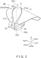
- FIG. 3 is a perspective view of the former 20.
- FIG. 4 is a perspective view showing a method of manufacturing the former 20.
- the former 20 is a forming mechanism that folds and guides the sheet-like packaging material F supplied from the packaging material supply unit 10.
- the former 20 mainly includes a collar member 21, a first tube member 22, and a first flange 23. It will be noted that FIG. 3 shows the first flange 23 partially transparent (i.e., illustrated via broken lines) for clarity.
- the collar member 21 is a tabular member that guides, along its surface toward the inner periphery of the first tube member 22, the packaging material F conveyed by the pull-down belt mechanisms 50.
- a U-shaped notch 21a connected to an upper end surface 22us of the first tube member 22.
- the collar member 21 is mainly formed in the shape of shoulders heading downward and outwardly away from the notch 21a in order to fold the sheet-like packaging material F toward the first tube member 22.
- the first tube member 22 is a substantially cylindrical member that forms in a tubular shape the packaging material F guided by the collar member 21 and guides the packaging material F to the outer periphery of the wraparound member 30.
- the first tube member 22 are mainly formed a cutout portion 22a and a first mating portion 22b.
- the cutout portion 22a is a portion to which is connected an edge 21ae of the collar member 21 defining the notch 21a.
- the cutout portion 22a is formed in the upper end surface 22us of the first tube member 22.
- An upper end 22u of the first tube member 22 is formed in a curve that traces the shape of a drop of water when viewed along the up and down direction.
- the upper end surface 22us is a flat surface formed parallel to the surface of the edge 21ae of the collar member 21.
- the upper end surface 22us is a flat surface formed in such a way that, starting at the upper end 22u, it heads downward and away along the radial direction from a central axis 22cl of the first tube member 22.
- FIG. 5 is a sectional view showing the shape of the cutout portion 22a.
- FIG. 5 is a sectional view of the former 20 taken along line A-A' of FIG. 3 .
- a depth D of the cutout portion 22a from the upper end surface 22us of the first tube member 22 is formed greater than a plate thickness t of the collar member 21.
- the upper end surface 22us is an example of a surface on one end side of the first tube member 22.
- the cutout portion 22a is formed using cutting. More specifically, the cutout portion 22a is formed using milling. The edge 21ae and the cutout portion 22a are connected to each other using welding.
- the first mating portion 22b is a portion that is mated with the support member 40.
- the first mating portion 22b is a cylindrical portion formed across a predetermined width upward from a lower end 22d of the first tube member 22.
- the first mating portion 22b is formed in such a way that its outer periphery is in a mating relationship (in the present embodiment, a clearance fit) with the inner periphery of a first mating hole 41h (described later) formed in the support member 40.
- the first mating portion 22b is formed in such a way that its central axis coincides with the central axis 22cl of the first tube member 22.
- the first mating portion 22b is formed using cutting after the collar member 21 and the first tube member 22 have been connected to each other. More specifically, the first mating portion 22b is formed using a lathe by rotating the collar member 21 and the first tube member 22 about the central axis 22cl after the collar member 21 and the first tube member 22 have been connected to each other.
- the first flange 23 is a flange that secures the former 20 to a first support member 41.
- the first flange 23 is provided on the outer peripheral surface of the first tube member 22 below the upper end 22u and above the first mating portion 22b.
- the first flange 23 and the first tube member 22 are secured to each other using welding.
- the first flange 23 is secured using bolts to the first support member 41.
- FIG. 6 is a perspective view of the wraparound member 30.
- the packaging material F wrapped around the wraparound member 30 becomes the tubular packaging material Fm as a result of a longitudinal seal (described later) being formed therein.
- the wraparound member 30 mainly includes a second tube member 31 and a chute 32. It will be noted that FIG. 6 shows a second flange 32f (described later) partially transparent (i.e., shown in broken lines) for clarity.
- the second tube member 31 is a substantially cylindrical member around whose outer periphery the packaging material F is wrapped.
- the second tube member 31 has an upper end 31u connected to a lower end 32ad (described later) of the chute 32.
- the outer circumference of the second tube member 31 is formed smaller than the inner circumference of the first tube member 22.
- first surfaces 31a and a second surface 31b are both areas formed as flat surfaces.
- the first surfaces 31a are formed so as to oppose pull-down belts 51 across the packaging material F.
- the second surface 31b is formed so as to oppose the longitudinal sealing mechanism 60 across the packaging material F.
- the first surfaces 31a are formed using cutting after the second tube member 31 and the chute 32 have been connected to each other.
- the second surface 31b is formed using cutting after the second tube member 31 and the chute 32 have been connected to each other. More specifically, the first surfaces 31a and the second surface 31b are formed using milling.
- the chute 32 is a member that receives the packaging articles A dropping from the weighing machine 2 and guides them to the second tube member 31.
- the chute 32 mainly includes a funnel member 32a, a second mating portion 32b, and a second flange 32f.
- the funnel member 32a is a funnel-shaped member whose inner diameter becomes smaller from above to below.
- the funnel member 32a is disposed in such a way that its central axis 32cl coincides with a central axis 31cl of the second tube member 31.
- the funnel member 32a has an upper end 32au in which is formed an opening that receives the packaging articles A.
- the funnel member 32a has a lower end 32ad in which is formed an opening that is connected to the upper end of the second tube member 31.
- the central axis 32cl and the central axis 3 1 cl will be collectively called the central axes 3 1 cl, 32cl.
- the second flange 32f is a flange that secures the wraparound member 30 to a second support member 42.
- FIG. 7 is a plan view of the second flange 32f.
- FIG. 8 is a sectional view of the second flange 32f taken along line B-B' of FIG. 7 .
- the second flange 32f is provided on the outer peripheral surface of the funnel member 32a below the upper end 32au of the funnel member 32a and above the lower end 32ad.
- the second flange 32f and the funnel member 32a are secured to each other using welding.
- the second flange 32f is secured using bolts to the second support member 42.
- the second mating portion 32b is a portion that is mated with the support member 40.
- the second mating portion 32b is a cylindrical portion that projects downward from the lower surface of the second flange 32f.
- the second mating portion 32b is formed in such a way that its outer periphery is in a mating relationship (in the present embodiment, a clearance fit) with the inner periphery of a second mating hole 42h (described later).
- the second mating portion 32b is formed using cutting after the second tube member 31 and the funnel member 32a, having the second flange 32f secured to it, have been connected to each other. More specifically, the second mating portion 32b is formed using a lathe by rotating the second tube member 31 and the funnel member 32a, having the second flange 32f secured to it, about the central axes 31cl, 32cl after the second tube member 31 and the funnel member 32a, having the second flange 32f secured to it, have been connected to each other.
- FIG. 9 is a perspective view of the support member 40.
- the support member 40 is a member that supports the former 20 and the wraparound member 30.
- the support member 40 includes a first support member 41, a second support member 42, and two columnar members 43 (one of which is shown partially transparent (i.e., shown in broken lines) for clarity).
- the support member 40 is secured to a housing (not shown in the drawings) that houses the bagmaking and packaging machine 100.
- the first support member 41 is a member that supports the former 20.
- the first support member 41 supports the former 20 in such a way that the central axis 22cl of the first tube member 22 lies along the up and down direction.
- the first support member 41 is a tabular member.
- a circular first mating hole 41h into which the first mating portion 22b of the first tube member 22 is inserted.
- the first mating hole 41h is formed in such a way that its inner periphery is in a mating relationship with the first mating portion 22b.
- the second support member 42 is a member that supports the wraparound member 30.
- the second support member 42 supports the wraparound member 30 in such a way that the central axes 31cl, 32cl of the wraparound member 30 lie along the up and down direction.
- the second support member 42 is a tabular member.
- In the second support member 42 is formed a circular second mating hole 42h into which the second mating portion 32b of the chute 32 is inserted.
- the second mating hole 42h is formed in such a way that its inner periphery is in a mating relationship with the second mating portion 32b of the chute 32.
- the columnar members 43 are members that support the second support member 42 above the first support member 41.
- the columnar members 43 support the first support member 41 and the second support member 42 in such a way that a central axis 41hcl of the first mating hole 41h coincides with a central axis 42hcl of the second mating hole 42h. Because of this, the support member 40 supports the former 20 and the wraparound member 30 in such a way that the central axis 22cl coincides with the central axes 31cl, 32cl.
- the columnar members 43 are secured using bolts to the first support member 41 and the second support member 42.
- the pull-down belt mechanisms 50 suck hold of the packaging material F wrapped around the outer peripheral surface of the second tube member 31 and convey it downward along the length direction of the second tube member 31 (the up and down direction).
- the pull-down belt mechanisms 50 are disposed on both right and left sides of the second tube member 31 below the former 20.
- the pull-down belt mechanisms 50 each include a pull-down belt 51, a drive roller 52, and a follower roller 53.
- the pull-down belts 51 are belts having a suction function.
- the pull-down belts 51 bridge the drive rollers 52 and the follower rollers 53, which are disposed a predetermined width apart from each other in the up and down direction.
- drive devices not shown in the drawings
- the pull-down belts 51 convey the packaging material F downward while rotating between the drive rollers 52 and the follower rollers 53.
- the pull-down belts 51 can make contact with the packaging material F in a wider area and can more efficiently convey the packaging material F than in a case where the first surfaces 31a are not formed.
- the longitudinal sealing mechanism 60 presses the edges of the packaging material F wrapped around the outer peripheral surface of the second tube member 31 against the second tube member 31 with a fixed pressure along the length direction of the second tube member 31 (the up and down direction) and at the same time applies heat to and seals the edges to thereby form a longitudinal seal (the portion in FIG. 2 indicated by diagonal hatching).
- the longitudinal sealing mechanism 60 is disposed on the front side of the second tube member 31 below the former 20.
- the longitudinal sealing mechanism 60 can make contact with the packaging material F in a wider area and can more efficiently seal the tubular packaging material Fm than in a case where the second surface 3 1b is not formed.
- the transverse sealing mechanism 70 is a mechanism that seals upper and lower ends of the bags B by sealing the tubular packaging material Fm in the transverse direction.
- the transverse sealing mechanism 70 is disposed below the second tube member 31.
- the transverse sealing mechanism 70 has two sealing jaws 71 and drive mechanisms (not shown in the drawings).
- the sealing jaws 71 have heaters (not shown in the drawings) inside.
- the drive mechanisms drive the two sealing jaws 71 to clamp the tubular packaging material Fm from the front and rear directions at a predetermined timing.
- the sealing jaws 71 seal with the heaters the clamped part of the tubular packaging material Fm.
- the sheet-like packaging material F supplied from the packaging material supply unit 10 to the former 20 is guided along the surface of the collar member 21, folded by the upper end 22u of the first tube member 22, and thereafter formed in a tubular shape along the inner peripheral surface of the first tube member 22.
- the packaging material F formed in a tubular shape by the first tube member 22 passes through a gap G between the inner peripheral surface of the first tube member 22 and the outer peripheral surface of the second tube member 31 and becomes wrapped around the outer periphery of the second tube member 31.
- the packaging material F wrapped around the outer peripheral surface of the second tube member 31 is conveyed downward along the length direction of the second tube member 31 by the pull-down belt mechanisms 50, and thereafter the longitudinal seal is formed in the packaging material F by the longitudinal sealing mechanism 60.
- the packaging articles A weighed by the weighing machine 2 are sequentially dropped into the opening formed in the upper end 32au of the chute 32.
- the packaging articles A that have been dropped pass through the chute 32 and the second tube member 31 and are discharged from the opening formed in the lower end 31d of the second tube member 31.
- the two sealing jaws 71 precedingly clamp and transversely seal the tubular packaging material Fm to form the upper portion of the bag B and the bottom portion of the following bag B.
- the packaging articles A discharged from the opening formed in the lower end 31d of the second tube member 31 fill the tubular packaging material Fm whose bottom portion has been sealed.
- the two sealing jaws 71 clamp and transversely seal the tubular packaging material Fm above the space filled with the packaging articles A to thereby form the upper portion of the bag B and the bottom portion of the following bag B.
- FIG. 10 and FIG. 11 are perspective views for describing a procedure for assembling the former 20 and the wraparound member 30 to the support member 40.
- the assembly of the former 20 and the wraparound member 30 to the support member 40 can be performed by the following procedure.
- FIG. 10 shows the support member 40 partially transparent (i.e., removed) for clarity.
- FIG. 11 shows the second flange 32f partially transparent for clarity.
- the first tube member 22 of the former 20 is inserted from above into the first mating hole 41h in the first support member 41 so that the first mating portion 22b becomes mated with the first mating hole 41h (see FIG. 10 ). Because of this, the former 20 becomes positioned on the support member 40. Thereafter, the first flange 23 is secured to the first support member 41 using bolts.
- the second tube member 31 of the wraparound member 30 is inserted from above into, and in the order of, the second mating hole 42h in the second support member 42 and the inner periphery of the first tube member 22 (see FIG. 11 ).
- the second mating portion 32b becomes mated with the second mating hole 42h. Because of this, the wraparound member 30 becomes positioned on the support member 40. Thereafter, the second flange 32f is secured to the second support member 42 using bolts.
- the support member 40 supports the former 20 and the wraparound member 30 in such a way that the central axis 22cl coincides with the central axes 31cl, 32cl. For this reason, the former 20 and the wraparound member 30 are mutually positioned as a result of the first mating portion 22b being mated with the first mating hole 41h and the second mating portion 32b being mated with the second mating hole 42h.
- the central axis 22cl coincides with the central axes 31cl, 32cl, and the gap G through which the packaging material F passes is formed between the inner peripheral surface of the first tube member 22 and the outer peripheral surface of the second tube member 31, as a result of the first mating portion 22b being mated with the first mating hole 41h and the second mating portion 32b being mated with the second mating hole 42h.
- the former 20 folds and guides the packaging material F.
- the former 20 includes the collar member 21 that guides the packaging material F and the first tube member 22 for forming in a tubular shape the packaging material F guided by the collar member 21.
- the first tube member 22 has one end to which the collar member 21 is connected, and includes the first mating portion 22b.
- the bagmaking and packaging machine 100 forms the packaging material F in a tubular shape and packages the packaging articles A.
- the bagmaking and packaging machine 100 includes the former 20, the wraparound member 30, and the support member 40. Around the wraparound member 30 is wrapped the packaging material F folded by the former 20.
- the support member 40 supports the former 20 and the wraparound member 30.
- the first mating portion 22b is mated with the support member 40.
- the former 20 is positioned on the support member 40 by mating. Consequently, by the use of the bagmaking and packaging machine 100, the former 20 is positioned with high precision by simple assembly work.
- the wraparound member 30 includes the second tube member 31 and the chute 32.
- the second tube member 31 is a tubular member around which the packaging material F is wrapped.
- the chute 32 is a member that guides the packaging articles A to the second tube member 31.
- the chute 32 is connected to one end of the second tube member 31 and includes the second mating portion 32b that is mated with the support member 40.
- the wraparound member 30 is positioned on the support member 40 by mating. Consequently, by the use of the bagmaking and packaging machine 100, the former 20 and the wraparound member 30 are positioned with high precision by simple assembly work.
- the support member 40 includes the first support member 41 and the second support member 42.
- the first support member 41 supports the former 20.
- the second support member 42 supports the wraparound member 30.
- first support member 41 In the first support member 41 is formed the first mating hole 41h with which the first mating portion 22b is mated. In the second support member 42 is formed the second mating hole 42h with which the second mating portion 32b is mated.
- the central axis 41hcl of the first mating hole 41h coincides with the central axis 42hcl of the second mating hole 42h.
- the central axis 41hcl of the first mating hole 41h coincides with the central axis 42hcl of the second mating hole 42h.
- the former 20 and the wraparound member 30 are mutually positioned as a result of the first mating portion 22b being mated with the first mating hole 41h and the second mating portion 32b being mated with the second mating hole 42h. Consequently, by the use of the bagmaking and packaging machine 100, the former 20 and the wraparound member 30 are positioned with high precision by simple assembly work.
- the cutout portion 22a to which is connected the edge of the collar member 21 is formed across the circumferential direction in the upper end surface 22us.
- the collar member 21 is positioned by bringing the edge 21ae, which defines the notch 21a, into abutment with the cutout portion 22a. Consequently, by the use of the bagmaking and packaging machine 100, the collar member 21 is positioned on the first tube member 22 with high precision.
- the cutout portion 22a has the depth D that is greater than the plate thickness t of the collar member 21.
- the welded part of the collar member 21 which is a tabular member, deforms and projects slightly outward (in the present embodiment, upward) due to heat during welding.
- the projecting part formed in this way causes the packaging material F along the collar member 21 to slightly separate from the surface of the collar member 21 in the vicinity of the upper end 22u of the first tube member 22 and obstructs normal folding of the packaging material F at the upper end 22u of the first collar member 22.
- the depth D of the cutout portion 22a is formed greater than the plate thickness t of the collar member 21, so the upper end surface 22us of the first tube member 22 is not even with the surface of the collar member 21.
- the upper end surface 22us that is not even with the surface of the collar member 21 can make contact with the packaging material F that has slightly separated from the surface of the collar member 21 as described above, so the packaging material F can be normally folded at the upper end 22u of the first tube member 22. Consequently, by the use of the bagmaking and packaging machine 100, the occurrence of problems in the folding of the packaging material F at the upper end 22u of the first tube member 22 is inhibited.
- a method of manufacturing the bagmaking and packaging machine 100 includes a step of connecting the collar member 21 and the first tube member 22 to each other and thereafter forming the first mating portion 22b using cutting.
- the first mating portion 22b is formed with high precision using cutting, so the former 20 is positioned on the support member 40 with high precision.
- the method of manufacturing the bagmaking and packaging machine 100 includes a step of forming the second mating portion 32b using cutting.
- the second mating portion 32b is formed with high precision using cutting, so the wraparound member 30 is positioned on the support member 40 with high precision.
- the bagmaking and packaging machine 100 further includes the pull-down belts 51 that convey the packaging material F along the length direction of the second tube member 31.
- the method of manufacturing the bagmaking and packaging machine 100 includes a step of connecting the second tube member 31 and the chute 32 to each other and thereafter forming the first surfaces 31a that oppose the pull-down belts 51 in the outer peripheral surface of the second tube member 31 using cutting.
- the first surfaces 31a are formed with high precision using cutting.
- the bagmaking and packaging machine 100 further includes the longitudinal sealing mechanism 60 that seals the edges of the packaging material F along the length direction of the second tube member 31.
- the method of manufacturing the bagmaking and packaging machine 100 includes a step of connecting the second tube member 31 and the chute 32 to each other and thereafter forming the second surface 3 1b that opposes the longitudinal sealing mechanism 60 in the outer peripheral surface of the second tube member 31 using cutting.
- the second surface 3 1b is formed with high precision using cutting.
- the method of manufacturing the bagmaking and packaging machine 100 includes a step of forming the cutout portion 22a using cutting.
- the cutout portion 22a is formed with high precision using cutting. For this reason, deformation is inhibited from occurring in the edge 21ae of the collar member 21 during connection to the cutout portion 22a.
- Patent Literature 1 Japanese Patent Unexamined Publication No. 2012-86874A
Landscapes
- Engineering & Computer Science (AREA)
- Mechanical Engineering (AREA)
- Containers And Plastic Fillers For Packaging (AREA)
Abstract
Problem It is a problem to provide a former that is positioned with high precision by simple assembly work, a bagmaking and packaging machine using the former, and a method of manufacturing the bagmaking and packaging machine.Solution A bagmaking and packaging machine 100 forms a packaging material F in a tubular shape and packages packaging articles A. The bagmaking and packaging machine 100 includes a former 20, a wraparound member 30, and a support member 40. The former 20 folds and guides the packaging material F. Around the wraparound member 30 is wrapped the packaging material F folded by the former 20. The support member 40 supports the former 20 and the wraparound member 30.The former 20 includes a collar member 21 that guides the packaging material F and a first tube member 22 for forming in a tubular shape the packaging material F guided by the collar member 21. The first tube member 22 has one end to which the collar member 21 is connected, and includes a first mating portion 22b that is mated with the support member 40.
Description
- The present invention relates to a former, a bagmaking and packaging machine, and a method of manufacturing a bagmaking and packaging machine.
- Patent Literature 1 (
Japanese Patent Unexamined Publication No. 2012-86874A - In a bagmaking and packaging machine, the packaging material folded by the former needs to be formed in a cylindrical shape by the wraparound member without causing the packaging material to crease or become crooked. For this reason, high-precision positioning is required to assemble the former and the wraparound member. In assembling the former and the wraparound member, work is performed to secure the former and the wraparound member to a support member using welding or screws, for example, and thereafter to adjust their positions. Such assembly work including position adjustment is complicated.
- It is an object of the present invention to provide a former that is positioned with high precision by simple assembly work, a bagmaking and packaging machine using the former, and a method of manufacturing the bagmaking and packaging machine.
- A former according to a first aspect folds and guides a packaging material. The former includes a collar member that guides the packaging material and a first tube member for forming in a tubular shape the packaging material guided by the collar member. The first tube member has one end to which the collar member is connected, and includes a first mating portion.
- A bagmaking and packaging machine according to a second aspect forms a packaging material in a tubular shape and packages packaging articles. The bagmaking and packaging machine includes the aforementioned former, a wraparound member, and a support member. Around the wraparound member is wrapped the packaging material folded by the former. The support member supports the former and the wraparound member.
- The first mating portion is mated with the support member.
- In this bagmaking and packaging machine, the former is positioned on the support member by mating. Consequently, by the use of this bagmaking and packaging machine, the former is positioned with high precision by simple assembly work.
- A bagmaking and packaging machine according to a third aspect is the bagmaking and packaging machine of the second aspect, wherein the wraparound member includes a second tube member and a chute. The second tube member is a tubular member around which the packaging material is wrapped. The chute is a member that guides the packaging articles to the second tube member.
- The chute is connected to one end of the second tube member and includes a second mating portion that is mated with the support member.
- In this bagmaking and packaging machine, the wraparound member is positioned on the support member by mating. Consequently, by the use of this bagmaking and packaging machine, the former and the wraparound member are positioned with high precision by simple assembly work.
- A bagmaking and packaging machine according to a fourth aspect is the bagmaking and packaging machine of the third aspect, wherein the support member includes a first support member and a second support member. The first support member supports the former. The second support member supports the wraparound member.
- In the first support member is formed a first mating hole with which the first mating portion is mated. In the second support member is formed a second mating hole with which the second mating portion is mated.
- A central axis of the first mating hole coincides with a central axis of the second mating hole.
- In this bagmaking and packaging machine, the central axis of the first mating hole coincides with the central axis of the second mating hole. For this reason, the former and the wraparound member are mutually positioned as a result of the first mating portion being mated with the first mating hole and the second mating portion being mated with the second mating hole. Consequently, by the use of this bagmaking and packaging machine, the former and the wraparound member are positioned with high precision by simple assembly work.
- A bagmaking and packaging machine according to a fifth aspect is any of the bagmaking and packaging machines of the second aspect to the fourth aspect, wherein a cutout portion of the first tube member to which is connected an edge of the collar member is formed across the circumferential direction in a surface on the one end side of the first tube member.
- In this bagmaking and packaging machine, the collar member is positioned by bringing the edge, which defines a notch, into abutment with the cutout portion. Consequently, by the use of this bagmaking and packaging machine, the collar member is positioned on the first tube member with high precision.
- A bagmaking and packaging machine according to a sixth aspect is the bagmaking and packaging machine of the fifth aspect, wherein a depth of the cutout portion is greater than a plate thickness of the collar member.
- In this bagmaking and packaging machine, the depth of the cutout portion is formed greater than the plate thickness of the collar member, so an upper end surface of the first tube member is not even with the surface of the collar member. The upper end surface that is not even with the surface of the collar member can make contact with the packaging material that has slightly separated from the surface of the collar member, so the packaging material can be normally folded at the upper end of the first tube member. Consequently, by the use of this bagmaking and packaging machine, the occurrence of problems in the folding of the packaging material at the upper end of the first tube member is inhibited.
- A method of manufacturing a bagmaking and packaging machine according to a seventh aspect is a method of manufacturing any of the bagmaking and packaging machines of the second aspect to the sixth aspect, including a step of connecting the collar member and the first tube member to each other and thereafter forming the first mating portion using cutting.
- In this method of manufacturing the bagmaking and packaging machine, the first mating portion is formed with high precision using cutting, so the former is positioned on the support member with high precision.
- A method of manufacturing a bagmaking and packaging machine according to an eighth aspect is a method of manufacturing the bagmaking and packaging machine of the third aspect or the fourth aspect, including a step of forming the second mating portion using cutting.
- In this method of manufacturing the bagmaking and packaging machine, the second mating portion is formed with high precision using cutting, so the wraparound member is positioned on the support member with high precision.
- A method of manufacturing a bagmaking and packaging machine according to a ninth aspect is a method of manufacturing the bagmaking and packaging machine of the third aspect or the fourth aspect, wherein the bagmaking and packaging machine further includes pull-down belts that convey the packaging material along a length direction of the second tube member. The method of manufacturing the bagmaking and packaging machine includes a step of connecting the second tube member and the chute to each other and thereafter forming first surfaces that oppose the pull-down belts in an outer peripheral surface of the second tube member using cutting.
- In this method of manufacturing the bagmaking and packaging machine, the first surfaces are formed with high precision using cutting.
- A method of manufacturing a bagmaking and packaging machine according to a tenth aspect is a method of manufacturing the bagmaking and packaging machine of the third aspect or the fourth aspect, wherein the bagmaking and packaging machine further includes a longitudinal sealing mechanism that seals edges of the packaging material along a length direction of the second tube member. The method of manufacturing the bagmaking and packaging machine includes a step of connecting the second tube member and the chute to each other and thereafter forming a second surface that opposes the longitudinal sealing mechanism in an outer peripheral surface of the second tube member using cutting.
- In this method of manufacturing the bagmaking and packaging machine, the second surface is formed with high precision using cutting.
- A method of manufacturing a bagmaking and packaging machine according to an eleventh aspect is a method of manufacturing the bagmaking and packaging machine of the fifth aspect or the sixth aspect, including a step of forming the cutout portion using cutting.
- In this method of manufacturing the bagmaking and packaging machine, the cutout portion is formed with high precision using cutting. For this reason, deformation is inhibited from occurring in the edge of the collar member during connection to the cutout portion.
- By the use of the bagmaking and packaging machine, the former is positioned with high precision by simple assembly work. Furthermore, by the use of the method of manufacturing the bagmaking and packaging machine, the former is positioned on the support member with high precision.
-
-
FIG. 1 is a perspective view of an embodiment of a packaging machine including a bagmaking and packaging machine; -
FIG. 2 is a perspective view showing the schematic configuration of the bagmaking and packaging machine during operation; -
FIG. 3 is a perspective view of a former; -
FIG. 4 is a perspective view showing a method of manufacturing the former; -
FIG. 5 is a sectional view of the former taken along line A-A' ofFIG. 3 ; -
FIG. 6 is a perspective view of a wraparound member; -
FIG. 7 is a plan view of a second flange; -
FIG. 8 is a sectional view of the second flange taken along line B-B' ofFIG. 7 ; -
FIG. 9 is a perspective view of a support member; -
FIG. 10 is a perspective view for describing a procedure for assembling the former and the wraparound member to the support member; and -
FIG. 11 a perspective view for describing the procedure for assembling the former and the wraparound member to the support member. - A bagmaking and
packaging machine 100 and a former 20 according to an embodiment of the present invention will be described below. In the following description, the directions of up/down, right/left, and front/rear are defined as indicated by the arrows in the drawings. -
FIG. 1 is a perspective view of apackaging machine 1 including the bagmaking andpackaging machine 100.FIG. 2 is a perspective view showing the schematic configuration of the bagmaking andpackaging machine 100. Thepackaging machine 1 mainly includes a weighingmachine 2 and the bagmaking andpackaging machine 100. - The weighing
machine 2 weighs packaging articles A (i.e., articles that are to be packaged) put into bags B formed by the bagmaking andpackaging machine 100 and drops the packaging articles A toward the bagmaking andpackaging machine 100. The packaging articles A are not particularly limited; here, they are articles that are light in weight and large in size, such as potato chips. The bagmaking andpackaging machine 100 receives the packaging articles A dropping from the weighingmachine 2 and packages them in a packaging material F formed in a tubular shape (hereinafter also called a tubular packaging material Fm) to make the bags B. The bagmaking andpackaging machine 100 is disposed below the weighingmachine 2. The packaging material F is a film using resin as raw material. - The bagmaking and
packaging machine 100 mainly includes a packagingmaterial supply unit 10, the former 20, awraparound member 30, asupport member 40, two pull-downbelt mechanisms 50, alongitudinal sealing mechanism 60, and atransverse sealing mechanism 70. - The packaging
material supply unit 10 is a unit that supplies the sheet-like packaging material F to the former 20. The packagingmaterial supply unit 10 pays out the packaging material F from a roll set in the packagingmaterial supply unit 10 and supplies the packaging material F to the former 20. The packaging material F is a film made of resin. -
FIG. 3 is a perspective view of the former 20.FIG. 4 is a perspective view showing a method of manufacturing the former 20. The former 20 is a forming mechanism that folds and guides the sheet-like packaging material F supplied from the packagingmaterial supply unit 10. The former 20 mainly includes acollar member 21, afirst tube member 22, and afirst flange 23. It will be noted thatFIG. 3 shows thefirst flange 23 partially transparent (i.e., illustrated via broken lines) for clarity. - The
collar member 21 is a tabular member that guides, along its surface toward the inner periphery of thefirst tube member 22, the packaging material F conveyed by the pull-downbelt mechanisms 50. In thecollar member 21 is formed aU-shaped notch 21a connected to an upper end surface 22us of thefirst tube member 22. Thecollar member 21 is mainly formed in the shape of shoulders heading downward and outwardly away from thenotch 21a in order to fold the sheet-like packaging material F toward thefirst tube member 22. - The
first tube member 22 is a substantially cylindrical member that forms in a tubular shape the packaging material F guided by thecollar member 21 and guides the packaging material F to the outer periphery of thewraparound member 30. In thefirst tube member 22 are mainly formed acutout portion 22a and afirst mating portion 22b. - The
cutout portion 22a is a portion to which is connected an edge 21ae of thecollar member 21 defining thenotch 21a. Thecutout portion 22a is formed in the upper end surface 22us of thefirst tube member 22. An upper end 22u of thefirst tube member 22 is formed in a curve that traces the shape of a drop of water when viewed along the up and down direction. In the present embodiment, the upper end surface 22us is a flat surface formed parallel to the surface of the edge 21ae of thecollar member 21. In other words, the upper end surface 22us is a flat surface formed in such a way that, starting at the upper end 22u, it heads downward and away along the radial direction from a central axis 22cl of thefirst tube member 22. Thecutout portion 22a is formed across the circumferential direction in the upper end surface 22us.FIG. 5 is a sectional view showing the shape of thecutout portion 22a.FIG. 5 is a sectional view of the former 20 taken along line A-A' ofFIG. 3 . As shown inFIG. 5 , a depth D of thecutout portion 22a from the upper end surface 22us of thefirst tube member 22 is formed greater than a plate thickness t of thecollar member 21. The upper end surface 22us is an example of a surface on one end side of thefirst tube member 22. - The
cutout portion 22a is formed using cutting. More specifically, thecutout portion 22a is formed using milling. The edge 21ae and thecutout portion 22a are connected to each other using welding. - The
first mating portion 22b is a portion that is mated with thesupport member 40. Thefirst mating portion 22b is a cylindrical portion formed across a predetermined width upward from alower end 22d of thefirst tube member 22. Thefirst mating portion 22b is formed in such a way that its outer periphery is in a mating relationship (in the present embodiment, a clearance fit) with the inner periphery of afirst mating hole 41h (described later) formed in thesupport member 40. Thefirst mating portion 22b is formed in such a way that its central axis coincides with the central axis 22cl of thefirst tube member 22. - The
first mating portion 22b is formed using cutting after thecollar member 21 and thefirst tube member 22 have been connected to each other. More specifically, thefirst mating portion 22b is formed using a lathe by rotating thecollar member 21 and thefirst tube member 22 about the central axis 22cl after thecollar member 21 and thefirst tube member 22 have been connected to each other. - The
first flange 23 is a flange that secures the former 20 to afirst support member 41. Thefirst flange 23 is provided on the outer peripheral surface of thefirst tube member 22 below the upper end 22u and above thefirst mating portion 22b. - The
first flange 23 and thefirst tube member 22 are secured to each other using welding. Thefirst flange 23 is secured using bolts to thefirst support member 41. -
FIG. 6 is a perspective view of thewraparound member 30. Around the outer periphery of thewraparound member 30 is wrapped the packaging material F folded by the former 20. The packaging material F wrapped around thewraparound member 30 becomes the tubular packaging material Fm as a result of a longitudinal seal (described later) being formed therein. Thewraparound member 30 mainly includes asecond tube member 31 and achute 32. It will be noted thatFIG. 6 shows asecond flange 32f (described later) partially transparent (i.e., shown in broken lines) for clarity. - The
second tube member 31 is a substantially cylindrical member around whose outer periphery the packaging material F is wrapped. Thesecond tube member 31 has anupper end 31u connected to a lower end 32ad (described later) of thechute 32. The outer circumference of thesecond tube member 31 is formed smaller than the inner circumference of thefirst tube member 22. - In the outer peripheral surface of the
second tube member 31 are formed twofirst surfaces 31a and asecond surface 31b. Thefirst surfaces 31a and thesecond surface 31b are both areas formed as flat surfaces. Thefirst surfaces 31a are formed so as to oppose pull-downbelts 51 across the packaging material F. Thesecond surface 31b is formed so as to oppose thelongitudinal sealing mechanism 60 across the packaging material F. - The
first surfaces 31a are formed using cutting after thesecond tube member 31 and thechute 32 have been connected to each other. Likewise, thesecond surface 31b is formed using cutting after thesecond tube member 31 and thechute 32 have been connected to each other. More specifically, thefirst surfaces 31a and thesecond surface 31b are formed using milling. - The
chute 32 is a member that receives the packaging articles A dropping from the weighingmachine 2 and guides them to thesecond tube member 31. Thechute 32 mainly includes afunnel member 32a, asecond mating portion 32b, and asecond flange 32f. - The
funnel member 32a is a funnel-shaped member whose inner diameter becomes smaller from above to below. Thefunnel member 32a is disposed in such a way that its central axis 32cl coincides with a central axis 31cl of thesecond tube member 31. Thefunnel member 32a has an upper end 32au in which is formed an opening that receives the packaging articles A. Thefunnel member 32a has a lower end 32ad in which is formed an opening that is connected to the upper end of thesecond tube member 31. Hereinafter, the central axis 32cl and the central axis 3 1 cl will be collectively called the central axes 3 1 cl, 32cl. - The
second flange 32f is a flange that secures thewraparound member 30 to asecond support member 42.FIG. 7 is a plan view of thesecond flange 32f.FIG. 8 is a sectional view of thesecond flange 32f taken along line B-B' ofFIG. 7 . Thesecond flange 32f is provided on the outer peripheral surface of thefunnel member 32a below the upper end 32au of thefunnel member 32a and above the lower end 32ad. - The
second flange 32f and thefunnel member 32a are secured to each other using welding. Thesecond flange 32f is secured using bolts to thesecond support member 42. - The
second mating portion 32b is a portion that is mated with thesupport member 40. Thesecond mating portion 32b is a cylindrical portion that projects downward from the lower surface of thesecond flange 32f. Thesecond mating portion 32b is formed in such a way that its outer periphery is in a mating relationship (in the present embodiment, a clearance fit) with the inner periphery of asecond mating hole 42h (described later). - The
second mating portion 32b is formed using cutting after thesecond tube member 31 and thefunnel member 32a, having thesecond flange 32f secured to it, have been connected to each other. More specifically, thesecond mating portion 32b is formed using a lathe by rotating thesecond tube member 31 and thefunnel member 32a, having thesecond flange 32f secured to it, about the central axes 31cl, 32cl after thesecond tube member 31 and thefunnel member 32a, having thesecond flange 32f secured to it, have been connected to each other. -
FIG. 9 is a perspective view of thesupport member 40. Thesupport member 40 is a member that supports the former 20 and thewraparound member 30. Thesupport member 40 includes afirst support member 41, asecond support member 42, and two columnar members 43 (one of which is shown partially transparent (i.e., shown in broken lines) for clarity). Thesupport member 40 is secured to a housing (not shown in the drawings) that houses the bagmaking andpackaging machine 100. - The
first support member 41 is a member that supports the former 20. Thefirst support member 41 supports the former 20 in such a way that the central axis 22cl of thefirst tube member 22 lies along the up and down direction. In the present embodiment, thefirst support member 41 is a tabular member. In thefirst support member 41 is formed a circularfirst mating hole 41h into which thefirst mating portion 22b of thefirst tube member 22 is inserted. Thefirst mating hole 41h is formed in such a way that its inner periphery is in a mating relationship with thefirst mating portion 22b. - The
second support member 42 is a member that supports thewraparound member 30. Thesecond support member 42 supports thewraparound member 30 in such a way that the central axes 31cl, 32cl of thewraparound member 30 lie along the up and down direction. In the present embodiment, thesecond support member 42 is a tabular member. In thesecond support member 42 is formed a circularsecond mating hole 42h into which thesecond mating portion 32b of thechute 32 is inserted. Thesecond mating hole 42h is formed in such a way that its inner periphery is in a mating relationship with thesecond mating portion 32b of thechute 32. - The
columnar members 43 are members that support thesecond support member 42 above thefirst support member 41. Thecolumnar members 43 support thefirst support member 41 and thesecond support member 42 in such a way that a central axis 41hcl of thefirst mating hole 41h coincides with a central axis 42hcl of thesecond mating hole 42h. Because of this, thesupport member 40 supports the former 20 and thewraparound member 30 in such a way that the central axis 22cl coincides with the central axes 31cl, 32cl. In the present embodiment, thecolumnar members 43 are secured using bolts to thefirst support member 41 and thesecond support member 42. - The pull-down
belt mechanisms 50 suck hold of the packaging material F wrapped around the outer peripheral surface of thesecond tube member 31 and convey it downward along the length direction of the second tube member 31 (the up and down direction). The pull-downbelt mechanisms 50 are disposed on both right and left sides of thesecond tube member 31 below the former 20. The pull-downbelt mechanisms 50 each include a pull-downbelt 51, adrive roller 52, and afollower roller 53. - The pull-down
belts 51 are belts having a suction function. The pull-downbelts 51 bridge thedrive rollers 52 and thefollower rollers 53, which are disposed a predetermined width apart from each other in the up and down direction. When drive devices (not shown in the drawings) drive thedrive rollers 52 and thefollower rollers 53, the pull-downbelts 51 convey the packaging material F downward while rotating between thedrive rollers 52 and thefollower rollers 53. - Because the flat
first surfaces 31a are formed in the outer peripheral surface of thesecond tube member 31, the pull-downbelts 51 can make contact with the packaging material F in a wider area and can more efficiently convey the packaging material F than in a case where thefirst surfaces 31a are not formed. - The
longitudinal sealing mechanism 60 presses the edges of the packaging material F wrapped around the outer peripheral surface of thesecond tube member 31 against thesecond tube member 31 with a fixed pressure along the length direction of the second tube member 31 (the up and down direction) and at the same time applies heat to and seals the edges to thereby form a longitudinal seal (the portion inFIG. 2 indicated by diagonal hatching). Thelongitudinal sealing mechanism 60 is disposed on the front side of thesecond tube member 31 below the former 20. - Because the flat
second surface 31b is formed in the outer peripheral surface of thesecond tube member 31, thelongitudinal sealing mechanism 60 can make contact with the packaging material F in a wider area and can more efficiently seal the tubular packaging material Fm than in a case where the second surface 3 1b is not formed. - The
transverse sealing mechanism 70 is a mechanism that seals upper and lower ends of the bags B by sealing the tubular packaging material Fm in the transverse direction. Thetransverse sealing mechanism 70 is disposed below thesecond tube member 31. Thetransverse sealing mechanism 70 has two sealingjaws 71 and drive mechanisms (not shown in the drawings). The sealingjaws 71 have heaters (not shown in the drawings) inside. - The drive mechanisms drive the two sealing
jaws 71 to clamp the tubular packaging material Fm from the front and rear directions at a predetermined timing. The sealingjaws 71 seal with the heaters the clamped part of the tubular packaging material Fm. - The sheet-like packaging material F supplied from the packaging
material supply unit 10 to the former 20 is guided along the surface of thecollar member 21, folded by the upper end 22u of thefirst tube member 22, and thereafter formed in a tubular shape along the inner peripheral surface of thefirst tube member 22. The packaging material F formed in a tubular shape by thefirst tube member 22 passes through a gap G between the inner peripheral surface of thefirst tube member 22 and the outer peripheral surface of thesecond tube member 31 and becomes wrapped around the outer periphery of thesecond tube member 31. The packaging material F wrapped around the outer peripheral surface of thesecond tube member 31 is conveyed downward along the length direction of thesecond tube member 31 by the pull-downbelt mechanisms 50, and thereafter the longitudinal seal is formed in the packaging material F by thelongitudinal sealing mechanism 60. - Meanwhile, the packaging articles A weighed by the weighing
machine 2 are sequentially dropped into the opening formed in the upper end 32au of thechute 32. The packaging articles A that have been dropped pass through thechute 32 and thesecond tube member 31 and are discharged from the opening formed in thelower end 31d of thesecond tube member 31. Below thelower end 31d, the two sealingjaws 71 precedingly clamp and transversely seal the tubular packaging material Fm to form the upper portion of the bag B and the bottom portion of the following bag B. The packaging articles A discharged from the opening formed in thelower end 31d of thesecond tube member 31 fill the tubular packaging material Fm whose bottom portion has been sealed. Thereafter, the two sealingjaws 71 clamp and transversely seal the tubular packaging material Fm above the space filled with the packaging articles A to thereby form the upper portion of the bag B and the bottom portion of the following bag B. -
FIG. 10 andFIG. 11 are perspective views for describing a procedure for assembling the former 20 and thewraparound member 30 to thesupport member 40. The assembly of the former 20 and thewraparound member 30 to thesupport member 40 can be performed by the following procedure. It will be noted thatFIG. 10 shows thesupport member 40 partially transparent (i.e., removed) for clarity. Furthermore,FIG. 11 shows thesecond flange 32f partially transparent for clarity. - First, the
first tube member 22 of the former 20 is inserted from above into thefirst mating hole 41h in thefirst support member 41 so that thefirst mating portion 22b becomes mated with thefirst mating hole 41h (seeFIG. 10 ). Because of this, the former 20 becomes positioned on thesupport member 40. Thereafter, thefirst flange 23 is secured to thefirst support member 41 using bolts. - Next, the
second tube member 31 of thewraparound member 30 is inserted from above into, and in the order of, thesecond mating hole 42h in thesecond support member 42 and the inner periphery of the first tube member 22 (seeFIG. 11 ). When thesecond tube member 31 is inserted downward to a predetermined position, thesecond mating portion 32b becomes mated with thesecond mating hole 42h. Because of this, thewraparound member 30 becomes positioned on thesupport member 40. Thereafter, thesecond flange 32f is secured to thesecond support member 42 using bolts. - As mentioned above, the
support member 40 supports the former 20 and thewraparound member 30 in such a way that the central axis 22cl coincides with the central axes 31cl, 32cl. For this reason, the former 20 and thewraparound member 30 are mutually positioned as a result of thefirst mating portion 22b being mated with thefirst mating hole 41h and thesecond mating portion 32b being mated with thesecond mating hole 42h. Specifically, the central axis 22cl coincides with the central axes 31cl, 32cl, and the gap G through which the packaging material F passes is formed between the inner peripheral surface of thefirst tube member 22 and the outer peripheral surface of thesecond tube member 31, as a result of thefirst mating portion 22b being mated with thefirst mating hole 41h and thesecond mating portion 32b being mated with thesecond mating hole 42h. - (4-1)
The former 20 folds and guides the packaging material F. The former 20 includes thecollar member 21 that guides the packaging material F and thefirst tube member 22 for forming in a tubular shape the packaging material F guided by thecollar member 21. Thefirst tube member 22 has one end to which thecollar member 21 is connected, and includes thefirst mating portion 22b. The bagmaking andpackaging machine 100 forms the packaging material F in a tubular shape and packages the packaging articles A. The bagmaking andpackaging machine 100 includes the former 20, thewraparound member 30, and thesupport member 40. Around thewraparound member 30 is wrapped the packaging material F folded by the former 20. Thesupport member 40 supports the former 20 and thewraparound member 30. - The
first mating portion 22b is mated with thesupport member 40. - In the bagmaking and
packaging machine 100, the former 20 is positioned on thesupport member 40 by mating. Consequently, by the use of the bagmaking andpackaging machine 100, the former 20 is positioned with high precision by simple assembly work. - (4-2)
Thewraparound member 30 includes thesecond tube member 31 and thechute 32. Thesecond tube member 31 is a tubular member around which the packaging material F is wrapped. Thechute 32 is a member that guides the packaging articles A to thesecond tube member 31. - The
chute 32 is connected to one end of thesecond tube member 31 and includes thesecond mating portion 32b that is mated with thesupport member 40. - In the bagmaking and
packaging machine 100, thewraparound member 30 is positioned on thesupport member 40 by mating. Consequently, by the use of the bagmaking andpackaging machine 100, the former 20 and thewraparound member 30 are positioned with high precision by simple assembly work. - (4-3)
Thesupport member 40 includes thefirst support member 41 and thesecond support member 42. Thefirst support member 41 supports the former 20. Thesecond support member 42 supports thewraparound member 30. - In the
first support member 41 is formed thefirst mating hole 41h with which thefirst mating portion 22b is mated. In thesecond support member 42 is formed thesecond mating hole 42h with which thesecond mating portion 32b is mated. - The central axis 41hcl of the
first mating hole 41h coincides with the central axis 42hcl of thesecond mating hole 42h. - In the bagmaking and
packaging machine 100, the central axis 41hcl of thefirst mating hole 41h coincides with the central axis 42hcl of thesecond mating hole 42h. For this reason, the former 20 and thewraparound member 30 are mutually positioned as a result of thefirst mating portion 22b being mated with thefirst mating hole 41h and thesecond mating portion 32b being mated with thesecond mating hole 42h. Consequently, by the use of the bagmaking andpackaging machine 100, the former 20 and thewraparound member 30 are positioned with high precision by simple assembly work. - (4-4)
In thefirst tube member 22, thecutout portion 22a to which is connected the edge of thecollar member 21 is formed across the circumferential direction in the upper end surface 22us. - In the bagmaking and
packaging machine 100, thecollar member 21 is positioned by bringing the edge 21ae, which defines thenotch 21a, into abutment with thecutout portion 22a. Consequently, by the use of the bagmaking andpackaging machine 100, thecollar member 21 is positioned on thefirst tube member 22 with high precision. - (4-5)
Thecutout portion 22a has the depth D that is greater than the plate thickness t of thecollar member 21. - In a case where the edge 21ae of the
collar member 21 defining thenotch 21a and thecutout portion 22a are connected to each other using welding, sometimes the welded part of thecollar member 21, which is a tabular member, deforms and projects slightly outward (in the present embodiment, upward) due to heat during welding. The projecting part formed in this way causes the packaging material F along thecollar member 21 to slightly separate from the surface of thecollar member 21 in the vicinity of the upper end 22u of thefirst tube member 22 and obstructs normal folding of the packaging material F at the upper end 22u of thefirst collar member 22. - In the bagmaking and
packaging machine 100, the depth D of thecutout portion 22a is formed greater than the plate thickness t of thecollar member 21, so the upper end surface 22us of thefirst tube member 22 is not even with the surface of thecollar member 21. The upper end surface 22us that is not even with the surface of thecollar member 21 can make contact with the packaging material F that has slightly separated from the surface of thecollar member 21 as described above, so the packaging material F can be normally folded at the upper end 22u of thefirst tube member 22. Consequently, by the use of the bagmaking andpackaging machine 100, the occurrence of problems in the folding of the packaging material F at the upper end 22u of thefirst tube member 22 is inhibited. - (4-6)
A method of manufacturing the bagmaking andpackaging machine 100 includes a step of connecting thecollar member 21 and thefirst tube member 22 to each other and thereafter forming thefirst mating portion 22b using cutting. - In the method of manufacturing the bagmaking and
packaging machine 100, thefirst mating portion 22b is formed with high precision using cutting, so the former 20 is positioned on thesupport member 40 with high precision. - (4-7)
The method of manufacturing the bagmaking andpackaging machine 100 includes a step of forming thesecond mating portion 32b using cutting. - In the method of manufacturing the bagmaking and
packaging machine 100, thesecond mating portion 32b is formed with high precision using cutting, so thewraparound member 30 is positioned on thesupport member 40 with high precision. - (4-8)
The bagmaking andpackaging machine 100 further includes the pull-downbelts 51 that convey the packaging material F along the length direction of thesecond tube member 31. The method of manufacturing the bagmaking andpackaging machine 100 includes a step of connecting thesecond tube member 31 and thechute 32 to each other and thereafter forming thefirst surfaces 31a that oppose the pull-downbelts 51 in the outer peripheral surface of thesecond tube member 31 using cutting. - In the method of manufacturing the bagmaking and
packaging machine 100, thefirst surfaces 31a are formed with high precision using cutting. - (4-9)
The bagmaking andpackaging machine 100 further includes thelongitudinal sealing mechanism 60 that seals the edges of the packaging material F along the length direction of thesecond tube member 31. The method of manufacturing the bagmaking andpackaging machine 100 includes a step of connecting thesecond tube member 31 and thechute 32 to each other and thereafter forming the second surface 3 1b that opposes thelongitudinal sealing mechanism 60 in the outer peripheral surface of thesecond tube member 31 using cutting. - In the method of manufacturing the bagmaking and
packaging machine 100, the second surface 3 1b is formed with high precision using cutting. - (4-10)
The method of manufacturing the bagmaking andpackaging machine 100 includes a step of forming thecutout portion 22a using cutting. - In the method of manufacturing the bagmaking and
packaging machine 100, thecutout portion 22a is formed with high precision using cutting. For this reason, deformation is inhibited from occurring in the edge 21ae of thecollar member 21 during connection to thecutout portion 22a. -
- 1
- Packaging Machine
- 2
- Weighing Machine
- 10
- Packaging Material Supply Unit
- 20
- Former
- 21
- Collar Member
- 22
- First Tube Member
- 22a
- Cutout Portion
- 22b
- First Mating Portion
- 22cl
- Central Axis (First Tube Member)
- 22us
- Upper End Surface
- 30
- Wraparound Member
- 31
- Second Tube Member
- 31a
- First Surfaces
- 31b
- Second Surface
- 31cl
- Central Axis (Second Tube Member)
- 32
- Chute
- 32b
- Second Mating Portion
- 40
- Support Member
- 41
- First Support Member
- 41h
- First Mating Hole
- 41hcl
- Central Axis (First Mating Hole)
- 42
- Second Support Member
- 42h
- Second Mating Hole
- 42hcl
- Central Axis (Second Mating Hole)
- 50
- Pull-down Belt Mechanisms
- 51
- Pull-down Belts
- 60
- Longitudinal Sealing Mechanism
- 70
- Transverse Sealing Mechanism
- 100
- Bagmaking and Packaging Machine
- A
- Packaging Articles
- B
- Bags
- D
- Depth of Cutout Portion
- F
- Packaging Material
- Fm
- Tubular Packaging Material
- t
- Plate Thickness of Collar Member
- Patent Literature 1:
Japanese Patent Unexamined Publication No. 2012-86874A
Claims (11)
- A former that folds and guides a packaging material, the former comprising:a collar member that guides the packaging material; anda first tube member that forms in a tubular shape the packaging material guided by the collar member,wherein the first tube member has one end to which the collar member is connected, and includes a first mating portion.
- A bagmaking and packaging machine that forms a packaging material in a tubular shape and packages packaging articles, the bagmaking and packaging machine comprising:the former of claim 1;a wraparound member around which the packaging material folded by the former is to be wrapped; anda support member that supports the former and the wraparound member,wherein the first mating portion is mated with the support member.
- The bagmaking and packaging machine of claim 2, whereinthe wraparound member includes a tubular second tube member around which the packaging material is to be wrapped and a chute that guides the packaging articles to the second tube member, andthe chute is connected to one end of the second tube member and includes a second mating portion that is mated with the support member.
- The bagmaking and packaging machine of claim 3, whereinthe support member includes a first support member part that supports the former and a second support member part that supports the wraparound member,in the first support member part is formed a first mating hole with which the first mating portion is mated,in the second support member part is formed a second mating hole with which the second mating portion is mated, anda central axis of the first mating hole coincides with a central axis of the second mating hole.
- The bagmaking and packaging machine of claim 2, wherein in the first tube member, a cutout portion to which is connected an edge of the collar member is formed across the circumferential direction in a surface on the one end side of the first tube member.
- The bagmaking and packaging machine of claim 5, wherein the cutout portion has a depth that is greater than a plate thickness of the collar member.
- A method of manufacturing the bagmaking and packaging machine of any one of claims 2 to 6, comprising a step of connecting the collar member and the first tube member to each other and thereafter forming the first mating portion using cutting.
- A method of manufacturing the bagmaking and packaging machine of claim 3 or 4, comprising a step of forming the second mating portion using cutting.
- A method of manufacturing the bagmaking and packaging machine of claim 3 or 4, whereinthe bagmaking and packaging machine further includes pull-down belts that convey the packaging material along a length direction of the second tube member, andthe method comprises a step of connecting the second tube member and the chute to each other and thereafter forming first surfaces that oppose the pull-down belts in an outer peripheral surface of the second tube member using cutting.
- A method of manufacturing the bagmaking and packaging machine of claim 3 or 4, whereinthe bagmaking and packaging machine further includes a sealing mechanism that seals edges of the packaging material along a length direction of the second tube member, andthe method comprises a step of connecting the second tube member and the chute to each other and thereafter forming a second surface that opposes the sealing mechanism in an outer peripheral surface of the second tube member using cutting.
- A method of manufacturing the bagmaking and packaging machine of claim 5 or 6, comprising a step of forming the cutout portion using cutting.
Applications Claiming Priority (1)
| Application Number | Priority Date | Filing Date | Title |
|---|---|---|---|
| JP2022086167A JP2023173720A (en) | 2022-05-26 | 2022-05-26 | Bag making and packaging machine and manufacturing method of bag making and packaging machine |
Publications (1)
| Publication Number | Publication Date |
|---|---|
| EP4303134A1 true EP4303134A1 (en) | 2024-01-10 |
Family
ID=86603878
Family Applications (1)
| Application Number | Title | Priority Date | Filing Date |
|---|---|---|---|
| EP23175300.5A Pending EP4303134A1 (en) | 2022-05-26 | 2023-05-25 | Former, bagmaking and packaging machine, and method of manufacturing bagmaking and packaging machine |
Country Status (4)
| Country | Link |
|---|---|
| US (1) | US20230382576A1 (en) |
| EP (1) | EP4303134A1 (en) |
| JP (1) | JP2023173720A (en) |
| CN (1) | CN117125292A (en) |
Families Citing this family (1)
| Publication number | Priority date | Publication date | Assignee | Title |
|---|---|---|---|---|
| GB2640398A (en) * | 2024-04-15 | 2025-10-22 | Kenray Holding Ltd | Forming set |
Citations (4)
| Publication number | Priority date | Publication date | Assignee | Title |
|---|---|---|---|---|
| US3486424A (en) * | 1967-06-23 | 1969-12-30 | Woodman Co | Web former with wear insert |
| US5707329A (en) * | 1997-02-11 | 1998-01-13 | Pool; George H. | Narrow profile apparatus for forming tubes from plastic web stock |
| US6523325B1 (en) * | 1999-07-29 | 2003-02-25 | Sealstrip Corporation | Apparatus for making resealable packages and reclosable seals |
| JP2012086874A (en) | 2010-10-20 | 2012-05-10 | Sankei Giken Kogyo Co Ltd | Packaging machine former |
Family Cites Families (5)
| Publication number | Priority date | Publication date | Assignee | Title |
|---|---|---|---|---|
| JP3468558B2 (en) * | 1993-10-15 | 2003-11-17 | 株式会社川島製作所 | Vertical four-sided seal bag filling and packaging machine |
| FR2824806B1 (en) * | 2001-05-15 | 2003-09-19 | Flexico France Sarl | PROCESS FOR PRODUCING BAGS COMPRISING CURSOR-OPERATED CLOSING PROFILES, MANUFACTURING MACHINE AND BAGS OBTAINED |
| JP4766682B2 (en) * | 2006-03-29 | 2011-09-07 | 株式会社東京自働機械製作所 | Bag making equipment for vertical form bag filling and packaging machine |
| CN204776141U (en) * | 2015-07-15 | 2015-11-18 | 广东皇麦世家食品有限公司 | Powder packagine machine's trunk former |
| JP7323176B2 (en) * | 2019-12-16 | 2023-08-08 | 株式会社川島製作所 | Attachment structure of the filling tube unit to the main body of the device |
-
2022
- 2022-05-26 JP JP2022086167A patent/JP2023173720A/en active Pending
-
2023
- 2023-04-24 CN CN202310450877.XA patent/CN117125292A/en active Pending
- 2023-05-18 US US18/319,494 patent/US20230382576A1/en active Pending
- 2023-05-25 EP EP23175300.5A patent/EP4303134A1/en active Pending
Patent Citations (4)
| Publication number | Priority date | Publication date | Assignee | Title |
|---|---|---|---|---|
| US3486424A (en) * | 1967-06-23 | 1969-12-30 | Woodman Co | Web former with wear insert |
| US5707329A (en) * | 1997-02-11 | 1998-01-13 | Pool; George H. | Narrow profile apparatus for forming tubes from plastic web stock |
| US6523325B1 (en) * | 1999-07-29 | 2003-02-25 | Sealstrip Corporation | Apparatus for making resealable packages and reclosable seals |
| JP2012086874A (en) | 2010-10-20 | 2012-05-10 | Sankei Giken Kogyo Co Ltd | Packaging machine former |
Also Published As
| Publication number | Publication date |
|---|---|
| CN117125292A (en) | 2023-11-28 |
| US20230382576A1 (en) | 2023-11-30 |
| JP2023173720A (en) | 2023-12-07 |
Similar Documents
| Publication | Publication Date | Title |
|---|---|---|
| US20230382576A1 (en) | Former, bagmaking and packaging machine, and method of manufacturing bagmaking and packaging machine | |
| EP2489284A1 (en) | Zipper tape, packaging bag with zipper tape, method for producing packaging bag with zipper tape and production device therefor | |
| EP2495177B1 (en) | Bag-making packaging machine | |
| US4603540A (en) | Apparatus for making packaging bags | |
| US20120090283A1 (en) | Apparatus for welding and separating packaging materials | |
| WO2003055749A1 (en) | Filler | |
| CN101052566B (en) | Modular infeeds for automatic forms/fill/seal equipment | |
| CN1628055A (en) | Process for splicing a continuous strip of packets as well as the strip thus obtained | |
| JPH05193609A (en) | Packing device for small package | |
| JP7297357B1 (en) | VERTICAL FORMING, FILLING AND PACKAGING MACHINE, METHOD OF MANUFACTURING FILM PACKAGING BAG WITH CONTENT, FILM PACKAGING BAG WITH CONTENT | |
| EP2114772B1 (en) | Machine and method for packaging groups of products with dual heat-sealing system | |
| JP2019218141A (en) | Bag-making and packaging machine | |
| EP3222532B1 (en) | Orientation unit and method for causing a change in orientation of a parallelepiped-shaped article in a packing machine | |
| CA3224130A1 (en) | Method and packaging device for packaging discrete medicaments in pouches | |
| JP7476205B2 (en) | Method and system for manufacturing a package | |
| AU2017378531B2 (en) | Bag making and packaging machine | |
| JP2841204B2 (en) | Packaging method and equipment | |
| JP2010111425A (en) | Former ring for film forming mechanism of multiple line automatic packaging machine, film forming mechanism of multiple line automatic packaging machine, and multiple line automatic packaging machine | |
| AU2020458557B2 (en) | Bag-making and packaging machine | |
| JP5601897B2 (en) | Filling and packaging machine | |
| US20010049069A1 (en) | Method of and apparatus for manufacturing instant photography film unit | |
| JP6765785B2 (en) | Bag making and packaging machine | |
| JP2007290735A (en) | Method for manufacturing packaging bag performing gas substitution and vertical packaging machine | |
| JP5363959B2 (en) | Bag making and packaging machine and assembling method thereof | |
| CN214356945U (en) | Automatic tablet distribution and packaging system |
Legal Events
| Date | Code | Title | Description |
|---|---|---|---|
| PUAI | Public reference made under article 153(3) epc to a published international application that has entered the european phase |
Free format text: ORIGINAL CODE: 0009012 |
|
| STAA | Information on the status of an ep patent application or granted ep patent |
Free format text: STATUS: REQUEST FOR EXAMINATION WAS MADE |
|
| 17P | Request for examination filed |
Effective date: 20230525 |
|
| AK | Designated contracting states |
Kind code of ref document: A1 Designated state(s): AL AT BE BG CH CY CZ DE DK EE ES FI FR GB GR HR HU IE IS IT LI LT LU LV MC ME MK MT NL NO PL PT RO RS SE SI SK SM TR |