EP4303009A2 - Integrated circuit with address drivers for fluidic die - Google Patents
Integrated circuit with address drivers for fluidic die Download PDFInfo
- Publication number
- EP4303009A2 EP4303009A2 EP23210695.5A EP23210695A EP4303009A2 EP 4303009 A2 EP4303009 A2 EP 4303009A2 EP 23210695 A EP23210695 A EP 23210695A EP 4303009 A2 EP4303009 A2 EP 4303009A2
- Authority
- EP
- European Patent Office
- Prior art keywords
- memory elements
- address
- fluid
- array
- die
- Prior art date
- Legal status (The legal status is an assumption and is not a legal conclusion. Google has not performed a legal analysis and makes no representation as to the accuracy of the status listed.)
- Pending
Links
- 239000012530 fluid Substances 0.000 claims abstract description 172
- 230000015654 memory Effects 0.000 claims abstract description 154
- 230000006870 function Effects 0.000 claims abstract description 71
- 238000010586 diagram Methods 0.000 description 17
- 238000000034 method Methods 0.000 description 11
- 238000010304 firing Methods 0.000 description 8
- 238000004891 communication Methods 0.000 description 7
- 238000006073 displacement reaction Methods 0.000 description 7
- XUIMIQQOPSSXEZ-UHFFFAOYSA-N Silicon Chemical compound [Si] XUIMIQQOPSSXEZ-UHFFFAOYSA-N 0.000 description 6
- 229910052710 silicon Inorganic materials 0.000 description 6
- 239000010703 silicon Substances 0.000 description 6
- 239000000758 substrate Substances 0.000 description 6
- 238000003491 array Methods 0.000 description 4
- 230000004044 response Effects 0.000 description 4
- 239000012528 membrane Substances 0.000 description 3
- 230000000712 assembly Effects 0.000 description 2
- 238000000429 assembly Methods 0.000 description 2
- 238000010146 3D printing Methods 0.000 description 1
- JBRZTFJDHDCESZ-UHFFFAOYSA-N AsGa Chemical compound [As]#[Ga] JBRZTFJDHDCESZ-UHFFFAOYSA-N 0.000 description 1
- 229920002799 BoPET Polymers 0.000 description 1
- 229910001218 Gallium arsenide Inorganic materials 0.000 description 1
- 239000005041 Mylar™ Substances 0.000 description 1
- 230000006978 adaptation Effects 0.000 description 1
- 239000003795 chemical substances by application Substances 0.000 description 1
- 230000003111 delayed effect Effects 0.000 description 1
- 238000007876 drug discovery Methods 0.000 description 1
- 238000001035 drying Methods 0.000 description 1
- 238000005530 etching Methods 0.000 description 1
- 239000004744 fabric Substances 0.000 description 1
- 239000011521 glass Substances 0.000 description 1
- 238000010438 heat treatment Methods 0.000 description 1
- 239000000463 material Substances 0.000 description 1
- 238000005459 micromachining Methods 0.000 description 1
- 230000003287 optical effect Effects 0.000 description 1
- 238000000206 photolithography Methods 0.000 description 1
- 239000000843 powder Substances 0.000 description 1
- 239000002243 precursor Substances 0.000 description 1
- 230000037452 priming Effects 0.000 description 1
- 238000007639 printing Methods 0.000 description 1
- 238000005086 pumping Methods 0.000 description 1
- 230000003134 recirculating effect Effects 0.000 description 1
- 238000010792 warming Methods 0.000 description 1
Images


Classifications
-
- B—PERFORMING OPERATIONS; TRANSPORTING
- B41—PRINTING; LINING MACHINES; TYPEWRITERS; STAMPS
- B41J—TYPEWRITERS; SELECTIVE PRINTING MECHANISMS, i.e. MECHANISMS PRINTING OTHERWISE THAN FROM A FORME; CORRECTION OF TYPOGRAPHICAL ERRORS
- B41J2/00—Typewriters or selective printing mechanisms characterised by the printing or marking process for which they are designed
- B41J2/005—Typewriters or selective printing mechanisms characterised by the printing or marking process for which they are designed characterised by bringing liquid or particles selectively into contact with a printing material
- B41J2/01—Ink jet
- B41J2/015—Ink jet characterised by the jet generation process
- B41J2/04—Ink jet characterised by the jet generation process generating single droplets or particles on demand
- B41J2/045—Ink jet characterised by the jet generation process generating single droplets or particles on demand by pressure, e.g. electromechanical transducers
- B41J2/04501—Control methods or devices therefor, e.g. driver circuits, control circuits
- B41J2/04541—Specific driving circuit
-
- B—PERFORMING OPERATIONS; TRANSPORTING
- B41—PRINTING; LINING MACHINES; TYPEWRITERS; STAMPS
- B41J—TYPEWRITERS; SELECTIVE PRINTING MECHANISMS, i.e. MECHANISMS PRINTING OTHERWISE THAN FROM A FORME; CORRECTION OF TYPOGRAPHICAL ERRORS
- B41J2/00—Typewriters or selective printing mechanisms characterised by the printing or marking process for which they are designed
- B41J2/005—Typewriters or selective printing mechanisms characterised by the printing or marking process for which they are designed characterised by bringing liquid or particles selectively into contact with a printing material
- B41J2/01—Ink jet
- B41J2/015—Ink jet characterised by the jet generation process
- B41J2/04—Ink jet characterised by the jet generation process generating single droplets or particles on demand
- B41J2/045—Ink jet characterised by the jet generation process generating single droplets or particles on demand by pressure, e.g. electromechanical transducers
- B41J2/04501—Control methods or devices therefor, e.g. driver circuits, control circuits
- B41J2/04543—Block driving
-
- B—PERFORMING OPERATIONS; TRANSPORTING
- B41—PRINTING; LINING MACHINES; TYPEWRITERS; STAMPS
- B41J—TYPEWRITERS; SELECTIVE PRINTING MECHANISMS, i.e. MECHANISMS PRINTING OTHERWISE THAN FROM A FORME; CORRECTION OF TYPOGRAPHICAL ERRORS
- B41J2/00—Typewriters or selective printing mechanisms characterised by the printing or marking process for which they are designed
- B41J2/005—Typewriters or selective printing mechanisms characterised by the printing or marking process for which they are designed characterised by bringing liquid or particles selectively into contact with a printing material
- B41J2/01—Ink jet
- B41J2/015—Ink jet characterised by the jet generation process
- B41J2/04—Ink jet characterised by the jet generation process generating single droplets or particles on demand
- B41J2/045—Ink jet characterised by the jet generation process generating single droplets or particles on demand by pressure, e.g. electromechanical transducers
- B41J2/04501—Control methods or devices therefor, e.g. driver circuits, control circuits
- B41J2/0458—Control methods or devices therefor, e.g. driver circuits, control circuits controlling heads based on heating elements forming bubbles
-
- B—PERFORMING OPERATIONS; TRANSPORTING
- B41—PRINTING; LINING MACHINES; TYPEWRITERS; STAMPS
- B41J—TYPEWRITERS; SELECTIVE PRINTING MECHANISMS, i.e. MECHANISMS PRINTING OTHERWISE THAN FROM A FORME; CORRECTION OF TYPOGRAPHICAL ERRORS
- B41J2/00—Typewriters or selective printing mechanisms characterised by the printing or marking process for which they are designed
- B41J2/005—Typewriters or selective printing mechanisms characterised by the printing or marking process for which they are designed characterised by bringing liquid or particles selectively into contact with a printing material
- B41J2/01—Ink jet
- B41J2/015—Ink jet characterised by the jet generation process
- B41J2/04—Ink jet characterised by the jet generation process generating single droplets or particles on demand
- B41J2/045—Ink jet characterised by the jet generation process generating single droplets or particles on demand by pressure, e.g. electromechanical transducers
- B41J2/04501—Control methods or devices therefor, e.g. driver circuits, control circuits
- B41J2/04586—Control methods or devices therefor, e.g. driver circuits, control circuits controlling heads of a type not covered by groups B41J2/04575 - B41J2/04585, or of an undefined type
Definitions
- Some print components may include an array of nozzles and/or pumps each including a fluid chamber and a fluid actuator, where the fluid actuator may be actuated to cause displacement of fluid within the chamber.
- Some example fluidic dies may be printheads, where the fluid may correspond to ink or print agents.
- Print components include printheads for 2D and 3D printing systems and/or other high precision fluid dispense systems.
- EP1212197 discloses an apparatus that addresses ink jet heating elements based on image data to cause ejection of ink droplets toward a print medium.
- WO2019017951 discloses a fluidic die including sense architecture having a global sense block to provide an analog reference signal, and an array of distributed sense blocks, with each distributed sense block receiving the same set of addresses via an address bus.
- WO2019009902 discloses a circuit that includes a plurality of decoders responsive to a common address to activate respective control signals at different times for selecting respective memories of a fluid ejection device.
- US2018147839 discloses a printhead including EPROM having a plurality of cells, each cell having an address port.
- fluidic dies may include fluid actuators.
- the fluid actuators may include thermal resistor based actuators (e.g. for firing or recirculating fluid), piezoelectric membrane based actuators, electrostatic membrane actuators, mechanical/impact driven membrane actuators, magneto-strictive drive actuators, or other suitable devices that may cause displacement of fluid in response to electrical actuation.
- Fluidic dies described herein may include a plurality of fluid actuators, which may be referred to as an array of fluid actuators.
- An actuation may refer to singular or concurrent actuation of fluid actuators of the fluidic die to cause fluid displacement.
- An example of an actuation event is a fluid firing event whereby fluid is jetted through a nozzle.
- the array of fluid actuators may be arranged into sets of fluid actuators, where each such set of fluid actuators may be referred to as a "primitive” or a "firing primitive.”
- the number of fluid actuators in a primitive may be referred to as a size of the primitive.
- the fluid actuators of each primitive are addressable using a same set of actuation addresses, with each fluid actuator of a primitive corresponding to a different actuation address of the set of actuation addresses.
- the set of addresses are communicated to each primitive via an address bus which is shared by each primitive.
- each primitive receives actuation data (sometimes referred to as fire data or nozzle data) via a corresponding data line, and a fire signal (also referred to as a fire pulse) via a fire signal line.
- actuation data sometimes referred to as fire data or nozzle data
- a fire signal also referred to as a fire pulse
- the fluid actuator corresponding to the address communicated via the address line will actuate (e.g., fire) based on the actuation data corresponding to the primitive.
- electrical and fluidic operating constraints of a fluidic die may limit which fluid actuators of each primitive may be actuated concurrently for a given actuation event.
- Primitives facilitate actuation of fluid actuator subsets that may be concurrently actuated for a given actuation event to conform to such operating constraints.
- a fluidic die comprises four primitives, with each primitive including eight fluid actuators (with each fluid actuator corresponding to different address of a set of addresses 0 to 7), and where electrical and fluidic constraints limit actuation to one fluid actuator per primitive, a total of four fluid actuators (one from each primitive) may be concurrently actuated for a given actuation event. For example, for a first actuation event, the respective fluid actuator of each primitive corresponding to address "0" may be actuated. For a second actuation event, the respective fluid actuator of each primitive corresponding to address "5" may be actuated. As will be appreciated, such example is provided merely for illustration purposes, with fluidic dies contemplated herein may comprise more or fewer fluid actuators per primitive and more or fewer primitives per die.
- Example fluidic dies may include fluid chambers, orifices, and/or other features which may be defined by surfaces fabricated in a substrate of the fluidic die by etching, microfabrication (e.g., photolithography), micromachining processes, or other suitable processes or combinations thereof.
- Some example substrates may include silicon based substrates, glass based substrates, gallium arsenide based substrates, and/or other such suitable types of substrates for microfabricated devices and structures.
- fluid chambers may include ejection chambers in fluidic communication with nozzle orifices from which fluid may be ejected, and fluidic channels through which fluid may be conveyed.
- fluidic channels may be microfluidic channels where, as used herein, a microfluidic channel may correspond to a channel of sufficiently small size (e.g., of nanometer sized scale, micrometer sized scale, millimeter sized scale, etc.) to facilitate conveyance of small volumes of fluid (e.g., picoliter scale, nanoliter scale, microliter scale, milliliter scale, etc.).
- a microfluidic channel may correspond to a channel of sufficiently small size (e.g., of nanometer sized scale, micrometer sized scale, millimeter sized scale, etc.) to facilitate conveyance of small volumes of fluid (e.g., picoliter scale, nanoliter scale, microliter scale, milliliter scale, etc.).
- a fluid actuator may be arranged as part of a nozzle where, in addition to the fluid actuator, the nozzle includes an ejection chamber in fluidic communication with a nozzle orifice.
- the fluid actuator is positioned relative to the fluid chamber such that actuation of the fluid actuator causes displacement of fluid within the fluid chamber that may cause ejection of a fluid drop from the fluid chamber via the nozzle orifice.
- a fluid actuator arranged as part of a nozzle may sometimes be referred to as a fluid ejector or an ejecting actuator.
- a fluid actuator may be arranged as part of a pump where, in addition to the fluidic actuator, the pump includes a fluidic channel.
- the fluidic actuator is positioned relative to a fluidic channel such that actuation of the fluid actuator generates fluid displacement in the fluid channel (e.g., a microfluidic channel) to convey fluid within the fluidic die, such as between a fluid supply and a nozzle, for instance.
- An example of fluid displacement/pumping within the die is sometimes also referred to as microrecirculation.
- a fluid actuator arranged to convey fluid within a fluidic channel may sometimes be referred to as a non-ejecting or microrecirculation actuator.
- the fluid actuator may comprise a thermal actuator, where actuation of the fluid actuator (sometimes referred to as "firing") heats the fluid to form a gaseous drive bubble within the fluid chamber that may cause a fluid drop to be ejected from the nozzle orifice.
- fluid actuators may be arranged in arrays (such as columns, for example), where the actuators may be implemented as fluid ejectors and/or pumps, with selective operation of fluid ejectors causing fluid drop ejection and selective operation of pumps causing fluid displacement within the fluidic die.
- fluid actuators of such arrays may be arranged into primitives.
- Some fluidic die receive data in the form of data packets, sometimes referred to as fire pulse groups or a fire pulse group data packets, where each fire pulse group includes a head portion and a body portion.
- the head portion includes configuration data for on-die configuration functions such as address data (representing an address of the set of actuation addresses) for address drivers, fire pulse data for fire pulse control circuitry, and sensor data for sensor control circuitry (e.g., selecting and configuring thermal sensors), for instance.
- the body portion of each fire pulse group includes actuator data that selects which nozzles corresponding to the address represented by the address data in the head portion will be actuated in response to a fire pulse.
- an address driver receives address data bits from the head portion of each fire pulse group and drives the address represented by the data bits onto an address bus, with the address bus communicating the address to the array of fluidic actuators.
- address drivers In addition to driving the address represented by the address bits of the fire pulse group onto the address bus, in some cases, address drivers also drive the compliment of the address onto the address bus.
- Address driver circuitry consumes a relatively large amount of silicon area on a fluid die, thereby increasing a size and cost of the die.
- address driver circuitry is divided into multiple portions, with each portion driving a different portion of an address onto an address bus.
- the address driver is divided into two portions, each of the address driver circuitry driving a different portion of the actuation address onto the address bus.
- FIG. 1 is a block and schematic diagram generally illustrating an integrated circuit 30 for an array of fluid actuators, according to one example of the present disclosure.
- integrated circuit 30 is part of a fluid die, which will be described in greater detail below.
- Integrated circuit 30 includes an address bus 32 to communicate a set of addresses to an array of fluid actuating devices 34, illustrated at fluid actuating devices FA(0) to FA(n), where fluid actuating devices FA(0) to FA(n) are addressable using the set of addresses.
- each fluid actuating device FA(0) to FA(n) corresponds to a different one of the addresses of the set of addresses.
- fluid actuating devices FA(0) to FA(n) of array 34 are arranged to form a column.
- integrated circuit 30 includes a first group of configuration functions 36-1 including a first address driver 38-1 and a number of further functions illustrated as CF1(0) to CF1(a), and a second group of configuration functions 36-2 including a second address driver 38-2 and a number of further configuration functions illustrated as CF2(0) to CF2(b).
- the further configuration functions CF1(0) to CF1(a) and CF2(0) to CF2(b) of first and second groups of configuration functions 36-1 and 36-2 include, among others, a fire pulse control configuration function (e.g., to adjust warming, precursor, and fire pulse configurations), and sensor configuration functions (e.g., to select and control thermal sensor configurations), for example.
- a fire pulse control configuration function e.g., to adjust warming, precursor, and fire pulse configurations
- sensor configuration functions e.g., to select and control thermal sensor configurations
- first address driver 38-1 drives a first portion of an address of the set of addresses onto address bus 32
- second address driver 38-2 drives a remaining portion of the address of the set of addresses onto address bus 32, where at least one of the fluid actuating devices of the array of fluid actuating devices 34 corresponds to the address driven on address bus 32 by first and second address drivers 38-1 and 38-2.
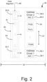
- Figure 2 is a block and schematic diagram illustrating an example of a fluidic die 40, in accordance with one example of the present disclosure.
- fluidic die 40 in addition to the array of fluid actuators 34 which, as described above, is addressable by a set of addresses, fluidic die 40 includes first address driver 38-1, which provides a first portion of an address of the set of address based on a first set of address bits 39-1, and second address driver 38-2, which provides a second portion of an address of the set of address based on a second set of address bits 39-2.
- the first and second sets of address bits together provide one address of the set of addresses.
- Fluidic die 40 further includes an array of memory elements 50, such as illustrated by memory element 51.
- array of memory elements 50 includes a first portion of memory elements 52-1 corresponding to first address driver 38-1, a second portion of memory elements 52-2 corresponding to second address driver 38-2, and a third portion of memory elements 54 corresponding to the array of fluid actuators 34.
- the array of memory elements 50 is to serially load data segments 60, each data segment including a series of data bits, such that upon completion of loading of a data segment 60, memory elements of first portion of memory elements 52-1 store the first set of address bits 39-1, and memory elements of second portion of memory elements 52-2 store the second set of address bits 39-2.
- first and second address drivers 38-1 and 38-2 respectively receive first and second sets of address bits 39-1 and 39-2 from first and second portions of memory elements 52-1 and 52-2 to provide the first and second portions of the address of the set of addresses to the array of fluid actuators 34.
- the fluid actuators of the array of fluid actuators 34 are arranged to form a column extending in a longitudinal direction 37.
- first and second address drivers 38-1 and 38-2 are disposed as opposite ends of the column of fluid actuators (FAs) of array 34.
- memory elements 41 of the array of memory elements 40 are arranged as a chain or series of memory elements implemented as a serial-to-parallel data converter, with the series memory elements disposed to extend in the longitudinal direction 37 of the array of fluid actuators 34, such that the first and second portions of memory elements 52-1 and 52-2 are respectively disposed proximate to first and second address drivers 38-1 and 38-2, and third portion of memory elements 54 is disposed proximate to the array of fluid actuators 34.
- first and second address drivers 38-1 and 38-2 are arranged at opposite ends of the column of fluid actuators, FA(0) to FA(n), of the array of fluid actuators 34, and by arranging the array of memory elements 50 as a chain of memory elements extending in longitudinal direction 37, an amount of silicon space required in at least one dimension of fluidic die 40, such as a width dimension, W, is lessened, thereby enabling a width of fluidic die 40 to be reduced.
- Figure 3 is a block and schematic diagram illustrating an example of fluidic die 40, in accordance with the present disclosure.
- the array of fluid actuators 34 is implemented as a column of fluid actuators, extending in longitudinal direction 37, with the column of fluid actuators arranged to form a number of primitives, illustrated as primitives P(0) to P(m).
- each primitive P(0) to P(m) has a number of fluid actuators, illustrated as fluid actuators FA(0) to FA(p).
- each primitive P(0) to P(m) uses the same set of addresses, with each fluid actuator FA(0) to FA(p) of each primitive corresponding to a different one of the addresses of the set of addresses, such as a different addresses of a set of addresses A(0) to A(p), for instance.
- First group of configuration functions 36-1 includes first address driver 38-1 and a number of additional configuration functions, CF1(0) to CF1(a), and second group of configuration functions 36-2 includes second address driver 38-2 and a number of additional configuration functions, CF2(0) to CF2(b).
- First address driver 38-1 drives a first portion of an address of the set of addresses on address bus 32 based on first set of address bits 39-1
- second address driver 38-2 drives a remaining portion of the address of the set of addresses based on second set of address bits 39-2, with address bus 32, in-turn, communicating the address to each primitive P(0) to P(m).
- first and second groups of configurations functions 36-1 and 36-2 are disposed in longitudinal direction 37 at opposite ends of array of fluid actuators 34.
- the array of memory elements 50 comprises a series or chain of memory elements 51 implemented as a serial-to-parallel data converter, with first portion 52-1 of memory elements 51 corresponding to first group of configuration functions 36-1, second portion of memory elements 52-2 corresponding to second group of configuration functions 36-2, and third portion of memory elements 54 corresponding to the array of fluid actuators 34, with each memory element 51 of the third portion 54 corresponding to a different one of the primitives P(0) to P(m).
- the array of memory elements 50 comprises a sequential logic circuit (e.g., flipflop arrays, latch arrays, etc.).
- the sequential logic circuit is adapted to function as a serial-in, parallel-out shift register.
- the chain of memory elements 51 of array 50 extends in longitudinal direction 37 with first portion of memory cells 52-1 disposed proximate to first group of configuration functions 36-1, second portion of memory cells 52-2 disposed proximate to second group of configuration functions 36-2, and third group of memory cells 54 extending between first and second portions of memory cells 52-1 and 52-2 and proximate to the column of fluid actuators (FAs) of array 34.
- first portion of memory cells 52-1 disposed proximate to first group of configuration functions 36-1
- second portion of memory cells 52-2 disposed proximate to second group of configuration functions 36-2
- third group of memory cells 54 extending between first and second portions of memory cells 52-1 and 52-2 and proximate to the column of fluid actuators (FAs) of array 34.
- FAs fluid actuators
- FIG. 4 is a block diagram generally illustrating an example of data segment 60 received by array of memory elements 50 of fluidic die 40.
- data segment 60 includes a series of data bits, such as illustrated by data bit 61, including a first portion of data bits 62-1, sometimes referred to as a "head”, a second portion of data bits 62-2, sometimes referred to as a "tail", and a third portion of data bits 64, sometimes referred to as a "body”.
- first, second, and third portions of data bits 62-1, 62-2, and 64 are collectively referred to as a fire pulse group.
- First portion of data bits 62-1 comprises data bits for first group of configuration functions 36-1, including first set of address data bits 39-1 for first address driver 38-1.
- Second portion of data bits 62-2 comprises data bits for second group of configuration functions 36-2, including second set of address data bits 39-2 for second address driver 38-2.
- Third portion of data bits 64 includes actuation data bits for array of fluid actuators 34, with each data bit 61 of third portion of data bits 64 corresponding to a different one of the primitives P(0) to P(m). The data bits of third portion of data bits 64 are sometimes referred to as primitive data.
- each data segment 60 of a series of such data segments is serially loaded into the array of memory elements 50, beginning with a first bit of head portion 62-1 and ending with a last bit of tail portion 62-2.
- the data bits 61 of head portion 62-1 of data segment 60 are stored in first portion of memory elements 52-1, with the first set of address bits 39-1 corresponding to first address driver 38-1.
- the data bits 61 of tail portion 62-2 of data segment 60 are stored in second portion of memory elements 52-2, with the second set of address bits 39-2 corresponding to second address driver 38-2.
- Data bits 61 of third portion 64 of data segment 60 are stored in third portion 54 of the array of memory elements 50.
- FIG. 5 is a block and schematic diagram generally illustrating portions of a primitive arrangement, such as primitive P(0) of Figure 3 .
- each fluid actuator, FA is illustrated as a thermal resistor in Figure 5 , and is connectable between a power source, VPP, and a reference potential (e.g., ground) via a corresponding controllable switch, such as illustrated by FETs 70.
- each primitive including primitive P(0), includes an AND-gate 72 receiving, at a first input, primitive data (e.g., actuator data) for primitive P(0) from corresponding memory element 51 of third group of memory elements 54 of the array of memory elements 50.
- primitive data e.g., actuator data
- AND-gate 72 receives a fire signal 74 (e.g., a fire pulse) which controls a duration of actuation or firing of a fluidic actuator, such as fluidic actuator FA(0).
- fire signal 74 is delayed by a delay element 76, with each primitive having a different delay so that the firing of fluid actuators is not simultaneous among primitives P(0) to P(m).
- each fluid actuator has a corresponding address decoder 78 receiving the address driven on address bus 32 by first and second address drivers 38-1 and 38-2, and a corresponding AND-gate 80 for controlling a gate of FET 70.
- AND-gate 80 receives the output of corresponding address decoder 78 at a first input, and the output of AND-gate 72 at a second input. It is noted that address decoder 78 and AND-gate 80 are repeated for each fluid actuator, FA, while AND-gate 72 and delay element 76 are repeated for each primitive.
- the fire pulse group data represented by the data bits 61 of head, tail, and body portions 62-1, 62-2, and 64 of data segment 60 is processed by the corresponding groups of configuration functions 38-1 to 38-2 and primitives P(0) to P(m) to operate selected fluid actuators (FAs) to circulate fluid or eject fluid drops.
- FAs fluid actuators
- the actuator data stored in memory element 51 corresponding to primitive P(0) has a logic high (e.g., "1") and a fire pulse signal 74 is present at the input of AND-gate 72, the output of AND-gate 72 is set to a logic "high".
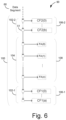
- FIG. 6 is a block and schematic diagram generally illustrating an integrated circuit 90 for an array of fluid actuators, according to one example of the present disclosure.
- integrated circuit 30 is implemented as part of a fluid die.
- Integrated circuit 90 includes a series of memory elements 100 including a first portion of memory elements 102-1 corresponding to a first group of die configuration functions 106-1, a second portion of memory elements 102-2 corresponding to a second group of die configuration functions 106-2, and a third portion of memory elements 104 corresponding to array of fluid actuators 108, with the memory elements of the third portion of memory elements 104 extending between the first and second portions of memory elements 102-1 and 102-2.
- array of fluid actuators 108 includes a number of fluid actuators indicated as fluid actuators FA(0) to F(n).
- first group of configuration functions 106-1 includes a number of configuration functions indicated as CF1(0) to CF1(a)
- second group of configuration functions 106-2 includes a number of configuration functions indicated as CF2(0) to CF2(b).
- die configuration functions may include functions such as address drivers for driving addresses associated with the array of fluid actuators 108, fire pulse control circuitry for adjusting actuation or firing times of fluid actuators of array of fluid actuators 108 via a fire signal, and sensor control circuitry for configuring sensor circuitry (e.g., selecting and configuring thermal sensors).
- the series of memory elements 100 serially loads data segments including a series of data bits, such as data segment 60 illustrated by Figure 4 , such that upon completion of loading of a data segment, the memory elements of the first portion of memory elements 102-1 store data bits for first group of die configuration functions 106-1, the second portion of memory elements 102-2 store data bits for second group of die configuration functions 106-2, and the third portion of memory elements 104 store data bits for array of fluid actuators 108.
- Fluid ejection system 200 includes a fluid ejection assembly, such as printhead assembly 204, and a fluid supply assembly, such as ink supply assembly 216.
- fluid ejection system 200 also includes a service station assembly 208, a carriage assembly 222, a print media transport assembly 226, and an electronic controller 230. While the following description provides examples of systems and assemblies for fluid handling with regard to ink, the disclosed systems and assemblies are also applicable to the handling of fluids other than ink.
- Printhead assembly 204 includes at least one printhead 212 which ejects drops of ink or fluid through a plurality of orifices or nozzles 214, where printhead 212 may be implemented, in one example, using integrated circuit 30 with fluid actuators FA(0) to FA(n) implemented as nozzles 214, as previously described herein by Figure 1 , for instance.
- the drops are directed toward a medium, such as print media 232, so as to print onto print media 232.
- print media 232 includes any type of suitable sheet material, such as paper, card stock, transparencies, Mylar, fabric, and the like.
- print media 232 includes media for three-dimensional (3D) printing, such as a powder bed, or media for bioprinting and/or drug discovery testing, such as a reservoir or container.
- nozzles 214 are arranged in at least one column or array such that properly sequenced ejection of ink from nozzles 214 causes characters, symbols, and/or other graphics or images to be printed upon print media 232 as printhead assembly 204 and print media 232 are moved relative to each other.
- Ink supply assembly 216 supplies ink to printhead assembly 204 and includes a reservoir 218 for storing ink. As such, in one example, ink flows from reservoir 218 to printhead assembly 204. In one example, printhead assembly 204 and ink supply assembly 216 are housed together in an inkjet or fluid-jet print cartridge or pen. In another example, ink supply assembly 216 is separate from printhead assembly 204 and supplies ink to printhead assembly 204 through an interface connection 220, such as a supply tube and/or valve.
- Carriage assembly 222 positions printhead assembly 204 relative to print media transport assembly 226, and print media transport assembly 226 positions print media 232 relative to printhead assembly 204.
- a print zone 234 is defined adjacent to nozzles 214 in an area between printhead assembly 204 and print media 232.
- printhead assembly 204 is a scanning type printhead assembly such that carriage assembly 222 moves printhead assembly 204 relative to print media transport assembly 226.
- printhead assembly 204 is a non-scanning type printhead assembly such that carriage assembly 222 fixes printhead assembly 204 at a prescribed position relative to print media transport assembly 226.
- Service station assembly 208 provides for spitting, wiping, capping, and/or priming of printhead assembly 204 to maintain the functionality of printhead assembly 204 and, more specifically, nozzles 214.
- service station assembly 208 may include a rubber blade or wiper which is periodically passed over printhead assembly 204 to wipe and clean nozzles 214 of excess ink.
- service station assembly 208 may include a cap that covers printhead assembly 204 to protect nozzles 214 from drying out during periods of non-use.
- service station assembly 208 may include a spittoon into which printhead assembly 204 ejects ink during spits to ensure that reservoir 218 maintains an appropriate level of pressure and fluidity, and to ensure that nozzles 214 do not clog or weep.
- Functions of service station assembly 208 may include relative motion between service station assembly 208 and printhead assembly 204.
- Electronic controller 230 communicates with printhead assembly 204 through a communication path 206, service station assembly 208 through a communication path 210, carriage assembly 222 through a communication path 224, and print media transport assembly 226 through a communication path 228.
- electronic controller 230 and printhead assembly 204 may communicate via carriage assembly 222 through a communication path 202.
- Electronic controller 230 may also communicate with ink supply assembly 216 such that, in one implementation, a new (or used) ink supply may be detected.
- Electronic controller 230 receives data 236 from a host system, such as a computer, and may include memory for temporarily storing data 236.
- Data 236 may be sent to fluid ejection system 200 along an electronic, infrared, optical or other information transfer path.
- Data 236 represent, for example, a document and/or file to be printed. As such, data 236 form a print job for fluid ejection system 200 and includes at least one print job command and/or command parameter.
- electronic controller 230 provides control of printhead assembly 204 including timing control for ejection of ink drops from nozzles 214. As such, electronic controller 230 defines a pattern of ejected ink drops which form characters, symbols, and/or other graphics or images on print media 232. Timing control and, therefore, the pattern of ejected ink drops, is determined by the print job commands and/or command parameters.
- logic and drive circuitry forming a portion of electronic controller 230 is located on printhead assembly 204. In another example, logic and drive circuitry forming a portion of electronic controller 230 is located off printhead assembly 204. In another example, logic and drive circuitry forming a portion of electronic controller 230 is located off printhead assembly 204. In one example, data segments 33-1 to 33-n, intermittent clock signal 35, fire signal 72, and mode signal 79 may be provided to print component 30 by electronic controller 230, where electronic controller 230 may be remote from print component 30.
- Figure 8 is a flow diagram generally illustrating a method 300 of operating a fluidic die, according to one example of the present disclosure, such as fluidic die 40 of Figure 3 , for instance.
- method 300 includes receiving data segments, each data segment having a head portion including a number of configuration data bits, a tail portion including a number of configuration data bits, and a body portion extending between the head portion and tail portion and including a number of actuation data bits, such as data segment 60 of Figure 4 including a head portion 62-1, a tail portion 62-2, and a body portion 64.
- method 300 includes serially loading each data segment into an array of memory elements including a first portion of memory elements corresponding to a first group of configuration functions, a second portion of memory elements corresponding to a second group of configuration functions, and a third portion of memory elements corresponding to an array of fluid actuators, such that upon loading of a data segment into the array of memory elements, the configuration bits of the head portion are stored in the first portion of memory elements, the configuration data bits of the tail portion of memory elements are stored in the second portion of memory elements, and the actuator data bits of the body portion are stored in the third portion of memory elements, such serially loading data segment 60 into array of memory elements 50 with first portion of memory elements 52-1 corresponding to a first group of configuration functions 36-1, second portion of memory elements 52-2 corresponding to a second group of configuration functions 36-2, and third portion of memory elements 54 corresponding to the array of fluid actuating devices 34.
Landscapes
- Particle Formation And Scattering Control In Inkjet Printers (AREA)
- Micromachines (AREA)
- Read Only Memory (AREA)
- Coating Apparatus (AREA)
- Semiconductor Integrated Circuits (AREA)
- Selective Calling Equipment (AREA)
- Static Random-Access Memory (AREA)
Abstract
Description
- Some print components may include an array of nozzles and/or pumps each including a fluid chamber and a fluid actuator, where the fluid actuator may be actuated to cause displacement of fluid within the chamber. Some example fluidic dies may be printheads, where the fluid may correspond to ink or print agents. Print components include printheads for 2D and 3D printing systems and/or other high precision fluid dispense systems.
EP1212197 discloses an apparatus that addresses ink jet heating elements based on image data to cause ejection of ink droplets toward a print medium.WO2019017951 discloses a fluidic die including sense architecture having a global sense block to provide an analog reference signal, and an array of distributed sense blocks, with each distributed sense block receiving the same set of addresses via an address bus.WO2019009902 discloses a circuit that includes a plurality of decoders responsive to a common address to activate respective control signals at different times for selecting respective memories of a fluid ejection device.US2018147839 discloses a printhead including EPROM having a plurality of cells, each cell having an address port. -
-
Figure 1 is a block and schematic diagram illustrating an integrated circuit for a fluidic die, according to one example. -
Figure 2 is a block and schematic diagram illustrating a fluidic die, according to one example. -
Figure 3 is a block and schematic diagram illustrating a fluidic die, according to one example. -
Figure 4 is a schematic diagram generally illustrating a data segment, according to one example. -
Figure 5 is a block and schematic diagram generally illustrating portions of a primitive arrangement, according to one example. -
Figure 6 is a block and schematic diagram illustrating an integrated circuit for a fluidic die, according to one example. -
Figure 7 is a schematic diagram illustrating a block diagram illustrating one example of a fluid ejection system. -
Figure 8 is a flow diagram illustrating a method of operating a fluidic die, according to one example. - Throughout the drawings, identical reference numbers designate similar, but not necessarily identical, elements. The figures are not necessarily to scale, and the size of some parts may be exaggerated to more clearly illustrate the example shown. Moreover the drawings provide examples and/or implementations consistent with the description; however, the description is not limited to the examples and/or implementations provided in the drawings.
- In the following detailed description, reference is made to the accompanying drawings which form a part hereof, and in which is shown by way of illustration specific examples in which the disclosure may be practiced. It is to be understood that other examples may be utilized and structural or logical changes may be made without departing from the scope of the present disclosure. The following detailed description, therefore, is not to be taken in a limiting sense, and the scope of the present disclosure is defined by the appended claims. It is to be understood that features of the various examples described herein may be combined, in part or whole, with each other, unless specifically noted otherwise.
- Examples of fluidic dies may include fluid actuators. The fluid actuators may include thermal resistor based actuators (e.g. for firing or recirculating fluid), piezoelectric membrane based actuators, electrostatic membrane actuators, mechanical/impact driven membrane actuators, magneto-strictive drive actuators, or other suitable devices that may cause displacement of fluid in response to electrical actuation. Fluidic dies described herein may include a plurality of fluid actuators, which may be referred to as an array of fluid actuators. An actuation may refer to singular or concurrent actuation of fluid actuators of the fluidic die to cause fluid displacement. An example of an actuation event is a fluid firing event whereby fluid is jetted through a nozzle.
- In example fluidic dies, the array of fluid actuators may be arranged into sets of fluid actuators, where each such set of fluid actuators may be referred to as a "primitive" or a "firing primitive." The number of fluid actuators in a primitive may be referred to as a size of the primitive. In some examples, the fluid actuators of each primitive are addressable using a same set of actuation addresses, with each fluid actuator of a primitive corresponding to a different actuation address of the set of actuation addresses. In examples, the set of addresses are communicated to each primitive via an address bus which is shared by each primitive.
- In one example, in addition to address data, each primitive receives actuation data (sometimes referred to as fire data or nozzle data) via a corresponding data line, and a fire signal (also referred to as a fire pulse) via a fire signal line. In one example, during an actuation or firing event, in response to a fire signal being present of the fire signal line, in each primitive, the fluid actuator corresponding to the address communicated via the address line will actuate (e.g., fire) based on the actuation data corresponding to the primitive.
- In some cases, electrical and fluidic operating constraints of a fluidic die may limit which fluid actuators of each primitive may be actuated concurrently for a given actuation event. Primitives facilitate actuation of fluid actuator subsets that may be concurrently actuated for a given actuation event to conform to such operating constraints.
- To illustrate by way of example, if a fluidic die comprises four primitives, with each primitive including eight fluid actuators (with each fluid actuator corresponding to different address of a set of
addresses 0 to 7), and where electrical and fluidic constraints limit actuation to one fluid actuator per primitive, a total of four fluid actuators (one from each primitive) may be concurrently actuated for a given actuation event. For example, for a first actuation event, the respective fluid actuator of each primitive corresponding to address "0" may be actuated. For a second actuation event, the respective fluid actuator of each primitive corresponding to address "5" may be actuated. As will be appreciated, such example is provided merely for illustration purposes, with fluidic dies contemplated herein may comprise more or fewer fluid actuators per primitive and more or fewer primitives per die. - Example fluidic dies may include fluid chambers, orifices, and/or other features which may be defined by surfaces fabricated in a substrate of the fluidic die by etching, microfabrication (e.g., photolithography), micromachining processes, or other suitable processes or combinations thereof. Some example substrates may include silicon based substrates, glass based substrates, gallium arsenide based substrates, and/or other such suitable types of substrates for microfabricated devices and structures. As used herein, fluid chambers may include ejection chambers in fluidic communication with nozzle orifices from which fluid may be ejected, and fluidic channels through which fluid may be conveyed. In some examples, fluidic channels may be microfluidic channels where, as used herein, a microfluidic channel may correspond to a channel of sufficiently small size (e.g., of nanometer sized scale, micrometer sized scale, millimeter sized scale, etc.) to facilitate conveyance of small volumes of fluid (e.g., picoliter scale, nanoliter scale, microliter scale, milliliter scale, etc.).
- In some examples, a fluid actuator may be arranged as part of a nozzle where, in addition to the fluid actuator, the nozzle includes an ejection chamber in fluidic communication with a nozzle orifice. The fluid actuator is positioned relative to the fluid chamber such that actuation of the fluid actuator causes displacement of fluid within the fluid chamber that may cause ejection of a fluid drop from the fluid chamber via the nozzle orifice. Accordingly, a fluid actuator arranged as part of a nozzle may sometimes be referred to as a fluid ejector or an ejecting actuator.
- In some examples, a fluid actuator may be arranged as part of a pump where, in addition to the fluidic actuator, the pump includes a fluidic channel. The fluidic actuator is positioned relative to a fluidic channel such that actuation of the fluid actuator generates fluid displacement in the fluid channel (e.g., a microfluidic channel) to convey fluid within the fluidic die, such as between a fluid supply and a nozzle, for instance. An example of fluid displacement/pumping within the die is sometimes also referred to as microrecirculation. A fluid actuator arranged to convey fluid within a fluidic channel may sometimes be referred to as a non-ejecting or microrecirculation actuator. In one example nozzle, the fluid actuator may comprise a thermal actuator, where actuation of the fluid actuator (sometimes referred to as "firing") heats the fluid to form a gaseous drive bubble within the fluid chamber that may cause a fluid drop to be ejected from the nozzle orifice. As described above, fluid actuators may be arranged in arrays (such as columns, for example), where the actuators may be implemented as fluid ejectors and/or pumps, with selective operation of fluid ejectors causing fluid drop ejection and selective operation of pumps causing fluid displacement within the fluidic die. In some examples, fluid actuators of such arrays may be arranged into primitives.
- Some fluidic die receive data in the form of data packets, sometimes referred to as fire pulse groups or a fire pulse group data packets, where each fire pulse group includes a head portion and a body portion. In some examples, the head portion includes configuration data for on-die configuration functions such as address data (representing an address of the set of actuation addresses) for address drivers, fire pulse data for fire pulse control circuitry, and sensor data for sensor control circuitry (e.g., selecting and configuring thermal sensors), for instance. In one example, the body portion of each fire pulse group includes actuator data that selects which nozzles corresponding to the address represented by the address data in the head portion will be actuated in response to a fire pulse.
- In some fluidic dies, an address driver receives address data bits from the head portion of each fire pulse group and drives the address represented by the data bits onto an address bus, with the address bus communicating the address to the array of fluidic actuators. In addition to driving the address represented by the address bits of the fire pulse group onto the address bus, in some cases, address drivers also drive the compliment of the address onto the address bus.
- Address driver circuitry consumes a relatively large amount of silicon area on a fluid die, thereby increasing a size and cost of the die. As will be described in greater detail herein, according to examples of the present disclosure, address driver circuitry is divided into multiple portions, with each portion driving a different portion of an address onto an address bus. In one example, the address driver is divided into two portions, each of the address driver circuitry driving a different portion of the actuation address onto the address bus. By dividing an address driver into multiple portions, an amount of silicon area required in at least one dimension, such as a width, thereby conserving silicon in at the least one dimension and enabling a fluidic die to be smaller in at least the one dimension.
-
Figure 1 is a block and schematic diagram generally illustrating anintegrated circuit 30 for an array of fluid actuators, according to one example of the present disclosure. In one example, integratedcircuit 30 is part of a fluid die, which will be described in greater detail below. Integratedcircuit 30 includes anaddress bus 32 to communicate a set of addresses to an array offluid actuating devices 34, illustrated at fluid actuating devices FA(0) to FA(n), where fluid actuating devices FA(0) to FA(n) are addressable using the set of addresses. In one example, each fluid actuating device FA(0) to FA(n) corresponds to a different one of the addresses of the set of addresses. In one example, fluid actuating devices FA(0) to FA(n) ofarray 34 are arranged to form a column. - In one example, integrated
circuit 30 includes a first group of configuration functions 36-1 including a first address driver 38-1 and a number of further functions illustrated as CF1(0) to CF1(a), and a second group of configuration functions 36-2 including a second address driver 38-2 and a number of further configuration functions illustrated as CF2(0) to CF2(b). In some cases, in addition to the address drives 38-1 and 38-2, the further configuration functions CF1(0) to CF1(a) and CF2(0) to CF2(b) of first and second groups of configuration functions 36-1 and 36-2 include, among others, a fire pulse control configuration function (e.g., to adjust warming, precursor, and fire pulse configurations), and sensor configuration functions (e.g., to select and control thermal sensor configurations), for example. - In operation, first address driver 38-1 drives a first portion of an address of the set of addresses onto
address bus 32, and second address driver 38-2 drives a remaining portion of the address of the set of addresses ontoaddress bus 32, where at least one of the fluid actuating devices of the array offluid actuating devices 34 corresponds to the address driven onaddress bus 32 by first and second address drivers 38-1 and 38-2. By dividing an address driver into multiple portions, such as into address drivers 38-1 and 38-2, as illustrated byFigure 1 , an amount of silicon space required for address driver circuitry in at least one dimension, such as a width dimension, W, is lessened, thereby enabling a fluidic die of whichintegrated circuit 30 may form a part to be smaller in at least the one dimension. -
Figure 2 is a block and schematic diagram illustrating an example of afluidic die 40, in accordance with one example of the present disclosure. According to the illustrated example, in addition to the array offluid actuators 34 which, as described above, is addressable by a set of addresses, fluidic die 40 includes first address driver 38-1, which provides a first portion of an address of the set of address based on a first set of address bits 39-1, and second address driver 38-2, which provides a second portion of an address of the set of address based on a second set of address bits 39-2. In one example, the first and second sets of address bits together provide one address of the set of addresses. - Fluidic die 40 further includes an array of
memory elements 50, such as illustrated bymemory element 51. According to one example, array ofmemory elements 50 includes a first portion of memory elements 52-1 corresponding to first address driver 38-1, a second portion of memory elements 52-2 corresponding to second address driver 38-2, and a third portion ofmemory elements 54 corresponding to the array offluid actuators 34. In one example, the array ofmemory elements 50 is to serially loaddata segments 60, each data segment including a series of data bits, such that upon completion of loading of adata segment 60, memory elements of first portion of memory elements 52-1 store the first set of address bits 39-1, and memory elements of second portion of memory elements 52-2 store the second set of address bits 39-2. According examples, first and second address drivers 38-1 and 38-2 respectively receive first and second sets of address bits 39-1 and 39-2 from first and second portions of memory elements 52-1 and 52-2 to provide the first and second portions of the address of the set of addresses to the array offluid actuators 34. - In one example, the fluid actuators of the array of
fluid actuators 34 are arranged to form a column extending in alongitudinal direction 37. In one arrangement, as illustrated, first and second address drivers 38-1 and 38-2 are disposed as opposite ends of the column of fluid actuators (FAs) ofarray 34. In one example, memory elements 41 of the array ofmemory elements 40 are arranged as a chain or series of memory elements implemented as a serial-to-parallel data converter, with the series memory elements disposed to extend in thelongitudinal direction 37 of the array offluid actuators 34, such that the first and second portions of memory elements 52-1 and 52-2 are respectively disposed proximate to first and second address drivers 38-1 and 38-2, and third portion ofmemory elements 54 is disposed proximate to the array offluid actuators 34. - By disposing the first and second address drivers 38-1 and 38-2 at opposite ends of the column of fluid actuators, FA(0) to FA(n), of the array of
fluid actuators 34, and by arranging the array ofmemory elements 50 as a chain of memory elements extending inlongitudinal direction 37, an amount of silicon space required in at least one dimension offluidic die 40, such as a width dimension, W, is lessened, thereby enabling a width of fluidic die 40 to be reduced. -
Figure 3 is a block and schematic diagram illustrating an example offluidic die 40, in accordance with the present disclosure. In one example, as illustrated the array offluid actuators 34 is implemented as a column of fluid actuators, extending inlongitudinal direction 37, with the column of fluid actuators arranged to form a number of primitives, illustrated as primitives P(0) to P(m). In example, each primitive P(0) to P(m) has a number of fluid actuators, illustrated as fluid actuators FA(0) to FA(p). In one example, each primitive P(0) to P(m) uses the same set of addresses, with each fluid actuator FA(0) to FA(p) of each primitive corresponding to a different one of the addresses of the set of addresses, such as a different addresses of a set of addresses A(0) to A(p), for instance. - First group of configuration functions 36-1 includes first address driver 38-1 and a number of additional configuration functions, CF1(0) to CF1(a), and second group of configuration functions 36-2 includes second address driver 38-2 and a number of additional configuration functions, CF2(0) to CF2(b). First address driver 38-1 drives a first portion of an address of the set of addresses on
address bus 32 based on first set of address bits 39-1, and second address driver 38-2 drives a remaining portion of the address of the set of addresses based on second set of address bits 39-2, withaddress bus 32, in-turn, communicating the address to each primitive P(0) to P(m). In one example, as illustrated, first and second groups of configurations functions 36-1 and 36-2 are disposed inlongitudinal direction 37 at opposite ends of array offluid actuators 34. - In one example, as illustrated, the array of
memory elements 50 comprises a series or chain ofmemory elements 51 implemented as a serial-to-parallel data converter, with first portion 52-1 ofmemory elements 51 corresponding to first group of configuration functions 36-1, second portion of memory elements 52-2 corresponding to second group of configuration functions 36-2, and third portion ofmemory elements 54 corresponding to the array offluid actuators 34, with eachmemory element 51 of thethird portion 54 corresponding to a different one of the primitives P(0) to P(m). In one example, the array ofmemory elements 50 comprises a sequential logic circuit (e.g., flipflop arrays, latch arrays, etc.). In one example, the sequential logic circuit is adapted to function as a serial-in, parallel-out shift register. - In one example, the chain of
memory elements 51 ofarray 50 extends inlongitudinal direction 37 with first portion of memory cells 52-1 disposed proximate to first group of configuration functions 36-1, second portion of memory cells 52-2 disposed proximate to second group of configuration functions 36-2, and third group ofmemory cells 54 extending between first and second portions of memory cells 52-1 and 52-2 and proximate to the column of fluid actuators (FAs) ofarray 34. - An example of the operation of
fluidic die 40, such as illustrated byFigure 3 , is described below with reference toFigures 4 and5 .Figure 4 is a block diagram generally illustrating an example ofdata segment 60 received by array ofmemory elements 50 of fluidic die 40. As illustrated,data segment 60 includes a series of data bits, such as illustrated bydata bit 61, including a first portion of data bits 62-1, sometimes referred to as a "head", a second portion of data bits 62-2, sometimes referred to as a "tail", and a third portion ofdata bits 64, sometimes referred to as a "body". Together, first, second, and third portions of data bits 62-1, 62-2, and 64 are collectively referred to as a fire pulse group. - First portion of data bits 62-1 comprises data bits for first group of configuration functions 36-1, including first set of address data bits 39-1 for first address driver 38-1. Second portion of data bits 62-2 comprises data bits for second group of configuration functions 36-2, including second set of address data bits 39-2 for second address driver 38-2. Third portion of
data bits 64 includes actuation data bits for array offluid actuators 34, with each data bit 61 of third portion ofdata bits 64 corresponding to a different one of the primitives P(0) to P(m). The data bits of third portion ofdata bits 64 are sometimes referred to as primitive data. - With reference to
Figure 3 (andFigure 2 ), eachdata segment 60 of a series of such data segments is serially loaded into the array ofmemory elements 50, beginning with a first bit of head portion 62-1 and ending with a last bit of tail portion 62-2. After being serially loaded or shifted into the array ofmemory elements 50, thedata bits 61 of head portion 62-1 ofdata segment 60 are stored in first portion of memory elements 52-1, with the first set of address bits 39-1 corresponding to first address driver 38-1. Similarly, thedata bits 61 of tail portion 62-2 ofdata segment 60 are stored in second portion of memory elements 52-2, with the second set of address bits 39-2 corresponding to second address driver 38-2.Data bits 61 ofthird portion 64 ofdata segment 60 are stored inthird portion 54 of the array ofmemory elements 50. -
Figure 5 is a block and schematic diagram generally illustrating portions of a primitive arrangement, such as primitive P(0) ofFigure 3 . In one example, each fluid actuator, FA, is illustrated as a thermal resistor inFigure 5 , and is connectable between a power source, VPP, and a reference potential (e.g., ground) via a corresponding controllable switch, such as illustrated byFETs 70. - According to one example, each primitive, including primitive P(0), includes an AND-gate 72 receiving, at a first input, primitive data (e.g., actuator data) for primitive P(0) from corresponding
memory element 51 of third group ofmemory elements 54 of the array ofmemory elements 50. At a second input,AND-gate 72 receives a fire signal 74 (e.g., a fire pulse) which controls a duration of actuation or firing of a fluidic actuator, such as fluidic actuator FA(0). In one example,fire signal 74 is delayed by adelay element 76, with each primitive having a different delay so that the firing of fluid actuators is not simultaneous among primitives P(0) to P(m). - In one example, each fluid actuator (FA) has a
corresponding address decoder 78 receiving the address driven onaddress bus 32 by first and second address drivers 38-1 and 38-2, and a corresponding AND-gate 80 for controlling a gate ofFET 70. AND-gate 80 receives the output ofcorresponding address decoder 78 at a first input, and the output of AND-gate 72 at a second input. It is noted thataddress decoder 78 and AND-gate 80 are repeated for each fluid actuator, FA, while AND-gate 72 anddelay element 76 are repeated for each primitive. - In one example, after being loaded into the array of
memory elements 50, the fire pulse group data represented by thedata bits 61 of head, tail, and body portions 62-1, 62-2, and 64 of data segment 60 (seeFigure 4 ) is processed by the corresponding groups of configuration functions 38-1 to 38-2 and primitives P(0) to P(m) to operate selected fluid actuators (FAs) to circulate fluid or eject fluid drops. For instance, with reference toFigure 5 , in one example, if the actuator data stored inmemory element 51 corresponding to primitive P(0) has a logic high (e.g., "1") and afire pulse signal 74 is present at the input ofAND-gate 72, the output ofAND-gate 72 is set to a logic "high". If the address driven onaddress bus 32 by first and second address drivers 38-1 and 38-2 in response to the sets of address bits 39-1 and 39-2 received from the corresponding memory elements of the first and second portions of memory elements 54-1 and 54-2 represents address "0", the output of Address Decoder "0" 78 is set to a logic "high". With the output of AND-gate 72 and Address Decoder "0" 78 each set to a logic "high", the output ofAND-gate 80 is also set to a logic "high", thereby turning "on" correspondingFET 70 to energize fluid actuator FA(0) to displace fluid (e.g., eject a fluid drop), where a duration for which fluid actuator FA(0) is based onfire pulse signal 74. -
Figure 6 is a block and schematic diagram generally illustrating anintegrated circuit 90 for an array of fluid actuators, according to one example of the present disclosure. In one example, integratedcircuit 30 is implemented as part of a fluid die. Integratedcircuit 90 includes a series ofmemory elements 100 including a first portion of memory elements 102-1 corresponding to a first group of die configuration functions 106-1, a second portion of memory elements 102-2 corresponding to a second group of die configuration functions 106-2, and a third portion ofmemory elements 104 corresponding to array offluid actuators 108, with the memory elements of the third portion ofmemory elements 104 extending between the first and second portions of memory elements 102-1 and 102-2. - In one example, array of
fluid actuators 108 includes a number of fluid actuators indicated as fluid actuators FA(0) to F(n). In one example, first group of configuration functions 106-1 includes a number of configuration functions indicated as CF1(0) to CF1(a), and second group of configuration functions 106-2 includes a number of configuration functions indicated as CF2(0) to CF2(b). In examples, die configuration functions may include functions such as address drivers for driving addresses associated with the array offluid actuators 108, fire pulse control circuitry for adjusting actuation or firing times of fluid actuators of array offluid actuators 108 via a fire signal, and sensor control circuitry for configuring sensor circuitry (e.g., selecting and configuring thermal sensors). - In examples, the series of
memory elements 100 serially loads data segments including a series of data bits, such asdata segment 60 illustrated byFigure 4 , such that upon completion of loading of a data segment, the memory elements of the first portion of memory elements 102-1 store data bits for first group of die configuration functions 106-1, the second portion of memory elements 102-2 store data bits for second group of die configuration functions 106-2, and the third portion ofmemory elements 104 store data bits for array offluid actuators 108. -
Figure 7 is a block diagram illustrating one example of afluid ejection system 200.Fluid ejection system 200 includes a fluid ejection assembly, such as printhead assembly 204, and a fluid supply assembly, such asink supply assembly 216. In the illustrated example,fluid ejection system 200 also includes aservice station assembly 208, acarriage assembly 222, a printmedia transport assembly 226, and anelectronic controller 230. While the following description provides examples of systems and assemblies for fluid handling with regard to ink, the disclosed systems and assemblies are also applicable to the handling of fluids other than ink. - Printhead assembly 204 includes at least one
printhead 212 which ejects drops of ink or fluid through a plurality of orifices ornozzles 214, whereprinthead 212 may be implemented, in one example, using integratedcircuit 30 with fluid actuators FA(0) to FA(n) implemented asnozzles 214, as previously described herein byFigure 1 , for instance. In one example, the drops are directed toward a medium, such asprint media 232, so as to print ontoprint media 232. In one example,print media 232 includes any type of suitable sheet material, such as paper, card stock, transparencies, Mylar, fabric, and the like. In another example,print media 232 includes media for three-dimensional (3D) printing, such as a powder bed, or media for bioprinting and/or drug discovery testing, such as a reservoir or container. In one example,nozzles 214 are arranged in at least one column or array such that properly sequenced ejection of ink fromnozzles 214 causes characters, symbols, and/or other graphics or images to be printed uponprint media 232 as printhead assembly 204 andprint media 232 are moved relative to each other. -
Ink supply assembly 216 supplies ink to printhead assembly 204 and includes areservoir 218 for storing ink. As such, in one example, ink flows fromreservoir 218 to printhead assembly 204. In one example, printhead assembly 204 andink supply assembly 216 are housed together in an inkjet or fluid-jet print cartridge or pen. In another example,ink supply assembly 216 is separate from printhead assembly 204 and supplies ink to printhead assembly 204 through aninterface connection 220, such as a supply tube and/or valve. -
Carriage assembly 222 positions printhead assembly 204 relative to printmedia transport assembly 226, and printmedia transport assembly 226positions print media 232 relative to printhead assembly 204. Thus, aprint zone 234 is defined adjacent tonozzles 214 in an area between printhead assembly 204 andprint media 232. In one example, printhead assembly 204 is a scanning type printhead assembly such thatcarriage assembly 222 moves printhead assembly 204 relative to printmedia transport assembly 226. In another example, printhead assembly 204 is a non-scanning type printhead assembly such thatcarriage assembly 222 fixes printhead assembly 204 at a prescribed position relative to printmedia transport assembly 226. -
Service station assembly 208 provides for spitting, wiping, capping, and/or priming of printhead assembly 204 to maintain the functionality of printhead assembly 204 and, more specifically, nozzles 214. For example,service station assembly 208 may include a rubber blade or wiper which is periodically passed over printhead assembly 204 to wipe andclean nozzles 214 of excess ink. In addition,service station assembly 208 may include a cap that covers printhead assembly 204 to protectnozzles 214 from drying out during periods of non-use. In addition,service station assembly 208 may include a spittoon into which printhead assembly 204 ejects ink during spits to ensure thatreservoir 218 maintains an appropriate level of pressure and fluidity, and to ensure thatnozzles 214 do not clog or weep. Functions ofservice station assembly 208 may include relative motion betweenservice station assembly 208 and printhead assembly 204. -
Electronic controller 230 communicates with printhead assembly 204 through acommunication path 206,service station assembly 208 through acommunication path 210,carriage assembly 222 through acommunication path 224, and printmedia transport assembly 226 through acommunication path 228. In one example, when printhead assembly 204 is mounted incarriage assembly 222,electronic controller 230 and printhead assembly 204 may communicate viacarriage assembly 222 through acommunication path 202.Electronic controller 230 may also communicate withink supply assembly 216 such that, in one implementation, a new (or used) ink supply may be detected. -
Electronic controller 230 receivesdata 236 from a host system, such as a computer, and may include memory for temporarily storingdata 236.Data 236 may be sent tofluid ejection system 200 along an electronic, infrared, optical or other information transfer path.Data 236 represent, for example, a document and/or file to be printed. As such,data 236 form a print job forfluid ejection system 200 and includes at least one print job command and/or command parameter. - In one example,
electronic controller 230 provides control of printhead assembly 204 including timing control for ejection of ink drops fromnozzles 214. As such,electronic controller 230 defines a pattern of ejected ink drops which form characters, symbols, and/or other graphics or images onprint media 232. Timing control and, therefore, the pattern of ejected ink drops, is determined by the print job commands and/or command parameters. In one example, logic and drive circuitry forming a portion ofelectronic controller 230 is located on printhead assembly 204. In another example, logic and drive circuitry forming a portion ofelectronic controller 230 is located off printhead assembly 204. In another example, logic and drive circuitry forming a portion ofelectronic controller 230 is located off printhead assembly 204. In one example, data segments 33-1 to 33-n, intermittent clock signal 35,fire signal 72, and mode signal 79 may be provided toprint component 30 byelectronic controller 230, whereelectronic controller 230 may be remote fromprint component 30. -
Figure 8 is a flow diagram generally illustrating amethod 300 of operating a fluidic die, according to one example of the present disclosure, such as fluidic die 40 ofFigure 3 , for instance. At 302,method 300 includes receiving data segments, each data segment having a head portion including a number of configuration data bits, a tail portion including a number of configuration data bits, and a body portion extending between the head portion and tail portion and including a number of actuation data bits, such asdata segment 60 ofFigure 4 including a head portion 62-1, a tail portion 62-2, and abody portion 64. - At 304,
method 300 includes serially loading each data segment into an array of memory elements including a first portion of memory elements corresponding to a first group of configuration functions, a second portion of memory elements corresponding to a second group of configuration functions, and a third portion of memory elements corresponding to an array of fluid actuators, such that upon loading of a data segment into the array of memory elements, the configuration bits of the head portion are stored in the first portion of memory elements, the configuration data bits of the tail portion of memory elements are stored in the second portion of memory elements, and the actuator data bits of the body portion are stored in the third portion of memory elements, such serially loadingdata segment 60 into array ofmemory elements 50 with first portion of memory elements 52-1 corresponding to a first group of configuration functions 36-1, second portion of memory elements 52-2 corresponding to a second group of configuration functions 36-2, and third portion ofmemory elements 54 corresponding to the array offluid actuating devices 34. - Although specific examples have been illustrated and described herein, a variety of alternate and/or equivalent implementations may be substituted for the specific examples shown and described without departing from the scope of the present disclosure. This application is intended to cover any adaptations or variations of the specific examples discussed herein. Therefore, it is intended that this disclosure be limited only by the claims and the equivalents thereof.
-
- 1. An integrated circuit for a fluidic die comprising:
- an address bus to communicate a set of addresses;
- a first group of die configuration functions including a first address driver to drive a first portion of an address of the set of addresses on the address bus;
- a second group of die configuration functions including a second address driver to drive a second portion of the address of the set of addresses on the address bus; and
- an array of fluid actuating devices addressable by the set of addresses communicated via the address bus.
- 2. The integrated circuit of
clause 1, the first portion and second portion together representing the address of the set of addresses. - 3. The integrated circuit of
clauses - 4. The integrated circuit of any of clauses 1-3, including:
- an array of memory elements including:
- a first portion of memory elements corresponding to the first group of die configuration functions;
- a second portion of memory elements corresponding to the second group of die configuration functions; and
- a third portion of memory element corresponding to the array of fluid actuating devices;
- the array of memory elements to serially load data segments such that upon completion of loading a data segment, the first portion of memory elements stores a first set of address bits representing the first portion of the address of the set of addresses, and the second portion of memory elements stores a second set of address bits representing the remaining portion of the address of the set of addresses.
- an array of memory elements including:
- 5. The integrated circuit of clause 4, the array of memory elements comprising a chain of memory elements to function as a serial-to-parallel data converter with the first portion of memory elements disposed proximate to the first group of die configuration functions, the second portion of memory elements disposed proximate to the second group of die configuration functions, and the third portion of memory elements extending between the first and second portions of memory elements and disposed proximate to the array of fluid actuating devices
- 6. The integrated circuit of any of clauses 1-5, in addition to first and second address drivers, the die configuration functions comprising a fire pulse control function and a sensor configuration function.
- 7. A fluidic die comprising:
- a column of fluid actuating devices addressable by a set of addresses;
- a first address driver to provide a first portion of an address of the set of addresses based on a first set of address bits;
- a second address driver to provide a remaining portion of the address of the set of addresses based on a second set of address bits; and
- an array of memory elements including a first portion of memory elements corresponding to the first address driver, and a second portion of memory elements corresponding to the second address driver, the array of memory elements to serially load data segments such that upon completion of loading a data segment the memory elements of the first portion store the first set of address bits and the memory elements of the second portion store the second set of address bits.
- 8. The fluidic die of clause 7, the array of memory elements including a third portion of memory elements corresponding to the column of fluid actuating devices.
- 9. The fluidic die of clause 7 or 8, the column of fluid actuating devices extending longitudinally between the first address driver and second address driver.
- 10. The fluidic die of any of clauses 7-9, the fluid actuators of the column of fluid actuators arranged to form a number of primitives, the fluid actuators of each primitive addressable by the set of addresses with each fluid actuator corresponding to a different of the addresses of the set of addresses, where each memory element of the third portion of memory elements corresponds to a different one of the primitives.
- 11. The fluidic die of any of clauses 7-10, the array of memory elements comprising a chain of memory elements to function as a serial-to-parallel data converted, the chain of memory elements extending in parallel with the column of fluid actuating devices with the first portion of memory elements disposed proximate to the first address driver, the second portion of memory elements disposed proximate to the second address driver, and the third portion of memory elements extending between the first and second portions of memory elements and disposed proximate to the column of fluid actuating devices.
- 12. An integrated circuit for fluid ejection comprising:
- a series of memory elements including:
- a first portion of memory elements corresponding to a first group of die configuration functions;
- a second portion corresponding to a second group of die configuration functions; and
- a third portion corresponding to fluid actuating devices, the third portion extending longitudinally between the first and second portions,
- the series of memory elements to serially load data segments comprising a number of data bits such that upon completion of loading of a data segment, the first portion of memory elements stores data bits for the first group of die configuration functions, the second portion of the memory elements stores data bits for the second group of die configuration functions, and the third portion of memory elements store data bits for the fluid actuating devices.
- a series of memory elements including:
- 13. The integrated circuit of clause 12, the fluid actuating devices disposed between the first and second groups of die configuration functions.
- 14. A method of operating a fluidic die comprising:
- receiving data segments, each data segment including:
- a head portion including a number of configuration data bits;
- a tail portion including a number of configuration data bits; and
- a body portion extending between the head portion and tail portion and including a number of actuation data bits;
- serially loading each data segment into an array of memory elements including a first portion of memory elements corresponding to a first group of configuration functions, a second portion of memory elements corresponding to a second group of configuration functions, and a third portion of memory elements corresponding to an array of fluid actuators, such that upon loading of a data segment into the array of memory elements, the configuration bits of the head portion are stored in the first portion of memory elements, the configuration data bits of the tail portion of memory elements are stored in the second portion of memory elements, and the actuator data bits of the body portion are stored in the third portion of memory elements.
- receiving data segments, each data segment including:
- 15. The method of clause 14, the head portion including a first set of address bits, the tail portion including a second set of address bits, the array of fluid actuators addressable with a set of addresses, the method including:
- communicating the set of addresses to the array of fluid actuators via an address bus;
- driving a first portion of an address of the set of address onto an address bus based on the first set of address bits with a first address driver of the first group of configuration functions; and
- driving a remaining portion of the address of the set of address onto the address bus based on the second set of address bits with a second address driver of the second group of configuration functions.
- 16. The method of clause 14 or 15, comprising:
arranging the array of memory elements as a series of memory elements implemented as a serial to parallel data converter, including disposing the series of memory elements in a longitudinal directional with the third portion of memory elements extending between the first and second portions of memory elements. - 17. The method of any of clauses 14-16, including:
arranging the first group of configuration function proximate to the first portion of memory elements, the second group of configuration functions proximate to the second portion of memory elements, and arranging the array of fluid actuators in a column extending in the longitudinal direction between the first and second groups of configuration functions and proximate to the third portion of memory elements.
Claims (7)
- A fluidic die (40) comprising:a column of fluid actuating devices (FA(0)-(n) addressable by a set of addresses;a first address driver (38-1) to provide a first portion of an address of the set of addresses based on a first set of address bits;a second address driver (38-2) to provide a remaining portion of the address of the set of addresses based on a second set of address bits; andan array of memory elements (50) including a first portion (52-1) of memory elements corresponding to the first address driver (38-1), and a second portion (52-2) of memory elements corresponding to the second address driver (38-2), the array of memory elements (50) to serially load data segments such that upon completion of loading a data segment the memory elements of the first portion (52-1) store the first set of address bits and the memory elements of the second portion (52-2) store the second set of address bits.
- The fluidic die (40) of claim 1, the array of memory elements (50) including a third portion of memory elements (54) corresponding to the column of fluid actuating devices (FA(0)-(n)).
- The fluidic die (40) of claim 1 or 2, the column of fluid actuating devices (FA(0)-(n)) extending longitudinally between the first address driver (38-1) and second address driver (38-2).
- The fluidic die (40) of any of claims 1-3, the fluid actuators of the column of fluid actuators (FA(0)-(n)) arranged to form a number of primitives, the fluid actuators of each primitive addressable by the set of addresses with each fluid actuator corresponding to a different of the addresses of the set of addresses, where each memory element of the third portion of memory elements (54) corresponds to a different one of the primitives.
- The fluidic die (40) of any of claims 1-4, the array of memory elements (50) comprising a chain of memory elements to function as a serial-to-parallel data converted, the chain of memory elements extending in parallel with the column of fluid actuating devices (FA(0)-(n)) with the first portion (52-1) of memory elements disposed proximate to the first address driver (38-1), the second portion (52-2) of memory elements disposed proximate to the second address driver (38-2), and the third portion of memory elements (54) extending between the first (52-1) and second (52-2) portions of memory elements and disposed proximate to the column of fluid actuating devices (FA(0)-(n)).
- An integrated circuit for fluid ejection comprising:
a series of memory elements including:a first portion (52-1) of memory elements corresponding to a first group of die configuration functions;a second portion (52-2) corresponding to a second group of die configuration functions; anda third portion (54) corresponding to fluid actuating devices (FA(0)-(n)), the third portion extending longitudinally between the first (52-1) and second (52-2) portions, the series of memory elements to serially load data segments comprising a number of data bits such that upon completion of loading of a data segment, the first portion (52-1) of memory elements stores data bits for the first group of die configuration functions, the second portion (52-2) of the memory elements stores data bits for the second group of die configuration functions, and the third portion of memory elements (54) store data bits for the fluid actuating devices. - The integrated circuit of claim 7, the fluid actuating devices (FA(0)-(n)) disposed between the first and second groups of die configuration functions.
Priority Applications (1)
| Application Number | Priority Date | Filing Date | Title |
|---|---|---|---|
| EP23210695.5A EP4303009A3 (en) | 2019-02-06 | 2019-02-06 | Integrated circuit with address drivers for fluidic die |
Applications Claiming Priority (3)
| Application Number | Priority Date | Filing Date | Title |
|---|---|---|---|
| EP23210695.5A EP4303009A3 (en) | 2019-02-06 | 2019-02-06 | Integrated circuit with address drivers for fluidic die |
| PCT/US2019/016818 WO2020162921A1 (en) | 2019-02-06 | 2019-02-06 | Integrated circuit with address drivers for fluidic die |
| EP19706171.6A EP3717254B1 (en) | 2019-02-06 | 2019-02-06 | Integrated circuit with address drivers for fluidic die |
Related Parent Applications (1)
| Application Number | Title | Priority Date | Filing Date |
|---|---|---|---|
| EP19706171.6A Division EP3717254B1 (en) | 2019-02-06 | 2019-02-06 | Integrated circuit with address drivers for fluidic die |
Publications (2)
| Publication Number | Publication Date |
|---|---|
| EP4303009A2 true EP4303009A2 (en) | 2024-01-10 |
| EP4303009A3 EP4303009A3 (en) | 2024-07-31 |
Family
ID=65494611
Family Applications (2)
| Application Number | Title | Priority Date | Filing Date |
|---|---|---|---|
| EP19706171.6A Active EP3717254B1 (en) | 2019-02-06 | 2019-02-06 | Integrated circuit with address drivers for fluidic die |
| EP23210695.5A Pending EP4303009A3 (en) | 2019-02-06 | 2019-02-06 | Integrated circuit with address drivers for fluidic die |
Family Applications Before (1)
| Application Number | Title | Priority Date | Filing Date |
|---|---|---|---|
| EP19706171.6A Active EP3717254B1 (en) | 2019-02-06 | 2019-02-06 | Integrated circuit with address drivers for fluidic die |
Country Status (20)
| Country | Link |
|---|---|
| US (2) | US11559985B2 (en) |
| EP (2) | EP3717254B1 (en) |
| JP (1) | JP7183434B2 (en) |
| KR (1) | KR20210104903A (en) |
| CN (1) | CN113365838B (en) |
| AR (1) | AR117889A1 (en) |
| AU (1) | AU2019428638B2 (en) |
| BR (1) | BR112021015384A2 (en) |
| CA (1) | CA3126273C (en) |
| CL (1) | CL2021001798A1 (en) |
| CO (1) | CO2021011669A2 (en) |
| ES (1) | ES2971835T3 (en) |
| HR (1) | HRP20240094T1 (en) |
| HU (1) | HUE065824T2 (en) |
| IL (1) | IL284543A (en) |
| MX (1) | MX2021008854A (en) |
| PL (1) | PL3717254T3 (en) |
| SG (1) | SG11202107305QA (en) |
| TW (1) | TWI736049B (en) |
| WO (1) | WO2020162921A1 (en) |
Families Citing this family (5)
| Publication number | Priority date | Publication date | Assignee | Title |
|---|---|---|---|---|
| PL3717247T3 (en) * | 2019-02-06 | 2021-11-29 | Hewlett-Packard Development Company, L.P. | Print component with memory array using intermittent clock signal |
| EP3921168A4 (en) | 2019-02-06 | 2022-11-30 | Hewlett-Packard Development Company, L.P. | Data packets comprising random numbers for controlling fluid dispensing devices |
| HUE065824T2 (en) | 2019-02-06 | 2024-06-28 | Hewlett Packard Development Co | Integrated circuit with address drivers for fluidic die |
| CN113412466B (en) | 2019-02-06 | 2024-05-07 | 惠普发展公司,有限责任合伙企业 | Fluid ejection controller interface, fluid ejection control method, and fluid ejection device |
| CN117396855A (en) * | 2021-09-02 | 2024-01-12 | 铠侠股份有限公司 | Storage system |
Citations (4)
| Publication number | Priority date | Publication date | Assignee | Title |
|---|---|---|---|---|
| EP1212197A1 (en) | 1999-08-05 | 2002-06-12 | Lexmark International, Inc. | Transitional ink jet heater addressing |
| US20180147839A1 (en) | 2014-01-17 | 2018-05-31 | Hewlett-Packard Development Company, L.P. | Addressing an eprom |
| WO2019009902A1 (en) | 2017-07-06 | 2019-01-10 | Hewlett-Packard Development Company, L.P. | Decoders for memories of fluid ejection devices |
| WO2019017951A1 (en) | 2017-07-20 | 2019-01-24 | Hewlett-Packard Development Company, L.P. | Fluidic die sense architecture |
Family Cites Families (71)
| Publication number | Priority date | Publication date | Assignee | Title |
|---|---|---|---|---|
| US4026402A (en) | 1975-07-28 | 1977-05-31 | Centronics Data Computer Corporation | Incremental line printer |
| US4872028A (en) | 1988-03-21 | 1989-10-03 | Hewlett-Packard Company | Thermal-ink-jet print system with drop detector for drive pulse optimization |
| JPH02208052A (en) | 1989-02-08 | 1990-08-17 | Canon Inc | Liquid jet recorder |
| JPH07205469A (en) | 1992-03-27 | 1995-08-08 | Nec Data Terminal Ltd | Thermal head |
| DE69333758T2 (en) * | 1992-10-08 | 2006-04-13 | Hewlett-Packard Development Co., L.P., Houston | Printhead with reduced connections to a printer |
| CA2168994C (en) | 1995-03-08 | 2000-01-18 | Juan J. Becerra | Method and apparatus for interleaving pulses in a liquid recorder |
| US5751302A (en) | 1996-03-29 | 1998-05-12 | Xerox Corporation | Transducer power dissipation control in a thermal ink jet printhead |
| EP0972374A1 (en) | 1998-02-04 | 2000-01-19 | Sun Microsystems, Inc. | Method and apparatus for efficient authentication and integrity checking using hierarchical hashing |
| AU1139100A (en) | 1998-10-16 | 2000-05-08 | Silverbrook Research Pty Limited | Improvements relating to inkjet printers |
| US6302507B1 (en) | 1999-10-13 | 2001-10-16 | Hewlett-Packard Company | Method for controlling the over-energy applied to an inkjet print cartridge using dynamic pulse width adjustment based on printhead temperature |
| US6616256B1 (en) | 2002-03-26 | 2003-09-09 | Lexmark International, Inc. | Serial integrated scan-based testing of ink jet print head |
| US6726300B2 (en) | 2002-04-29 | 2004-04-27 | Hewlett-Packard Development Company, L.P. | Fire pulses in a fluid ejection device |
| US6938993B2 (en) | 2002-10-31 | 2005-09-06 | Benq Corporation | Fluid injection head structure |
| JP4479239B2 (en) | 2003-01-10 | 2010-06-09 | リコープリンティングシステムズ株式会社 | Inkjet coating device |
| US7712675B2 (en) | 2003-01-15 | 2010-05-11 | Hewlett-Packard Development Company, L.P. | Physical items for holding data securely, and methods and apparatus for publishing and reading them |
| US6698862B1 (en) | 2003-01-16 | 2004-03-02 | Xerox Corporation | Method and apparatus for thermal ink jet drop volume control using variable prepulses |
| JP4158564B2 (en) | 2003-03-14 | 2008-10-01 | 富士ゼロックス株式会社 | Synchronous transmission system |
| JP4388303B2 (en) | 2003-05-16 | 2009-12-24 | 日本無線株式会社 | Array antenna communication device |
| JP4586354B2 (en) | 2003-11-25 | 2010-11-24 | ブラザー工業株式会社 | Drive device for recording head |
| US7444558B2 (en) | 2003-12-31 | 2008-10-28 | Intel Corporation | Programmable measurement mode for a serial point to point link |
| JP4546102B2 (en) | 2004-01-23 | 2010-09-15 | キヤノン株式会社 | Recording head substrate, recording head using the recording head substrate, recording apparatus including the recording head, and head cartridge including the recording head |
| US7240981B2 (en) | 2004-02-27 | 2007-07-10 | Hewlett-Packard Development Company, L.P. | Wide array fluid ejection device |
| US7738137B2 (en) | 2004-03-23 | 2010-06-15 | Lexmark International, Inc. | Inkjet print head synchronous serial output for data integrity |
| US7159959B2 (en) | 2004-05-05 | 2007-01-09 | Agilent Technologies, Inc. | Methods and systems for detecting errors in printhead pattern data and for preventing erroneous printing |
| US7866778B2 (en) | 2004-05-27 | 2011-01-11 | Silverbrook Research Pty Ltd | Printhead module having nozzle redundancy for faulty nozzle tolerance |
| KR100694053B1 (en) * | 2004-07-30 | 2007-03-12 | 삼성전자주식회사 | Print head driver of inkjet printer and semiconductor circuit board therefor |
| US8199342B2 (en) | 2004-10-29 | 2012-06-12 | Fujifilm Dimatix, Inc. | Tailoring image data packets to properties of print heads |
| US20060109296A1 (en) | 2004-11-04 | 2006-05-25 | Bassam Shamoun | Methods and apparatus for inkjet printing color filters for displays |
| JP4761520B2 (en) | 2005-08-02 | 2011-08-31 | キヤノン株式会社 | Recording apparatus and power supply control method |
| US7758141B2 (en) | 2006-06-23 | 2010-07-20 | Canon Kabushiki Kaisha | Printing apparatus for selectively driving heaters using a reduced number of data signal lines |
| EP2073983A4 (en) | 2006-10-09 | 2012-08-01 | Silverbrook Res Pty Ltd | Printhead ic with open actuator test |
| ES2539766T3 (en) | 2008-03-12 | 2015-07-03 | Hewlett-Packard Development Company, L.P. | Forwarding of trigger signal in a fluid ejection device |
| US8167411B2 (en) | 2008-05-08 | 2012-05-01 | Canon Kabushiki Kaisha | Print element substrate, inkjet printhead, and printing apparatus |
| ATE547249T1 (en) | 2008-05-08 | 2012-03-15 | Canon Kk | PRINTING ELEMENT SUBSTRATE, PRINT HEAD AND PRINTING APPARATUS |
| US20100124329A1 (en) | 2008-11-18 | 2010-05-20 | Lyman Dan C | Encrypted communication between printing system components |
| US7976115B2 (en) | 2008-12-31 | 2011-07-12 | Lexmark International, Inc. | Printhead nucleation detection using thermal response |
| JP5521466B2 (en) | 2009-09-30 | 2014-06-11 | ブラザー工業株式会社 | Driving circuit input inspection method and inspection apparatus |
| US8556364B2 (en) | 2010-07-01 | 2013-10-15 | Fujifilm Dimatix, Inc. | Determining whether a flow path is ready for ejecting a drop |
| US8777364B2 (en) | 2010-07-30 | 2014-07-15 | Hewlett-Packard Development Company, L.P. | Short circuit detection in an inkjet printhead |
| US8353567B1 (en) | 2010-09-08 | 2013-01-15 | Hewlett-Packard Development Company, L.P. | Drive waveform generation |
| TW201346749A (en) | 2012-02-08 | 2013-11-16 | Mush A Co Ltd | Data processing device, data processing system, data structure, recording medium, storage device and data processing method |
| US9162453B2 (en) | 2012-07-30 | 2015-10-20 | Hewlett-Packard Development Company, L.P. | Printhead including integrated circuit die cooling |
| JP5750414B2 (en) | 2012-08-27 | 2015-07-22 | 東芝テック株式会社 | Inkjet head drive device |
| JP5981815B2 (en) | 2012-09-18 | 2016-08-31 | キヤノン株式会社 | Printhead substrate and printing apparatus |
| CN103722907B (en) | 2012-10-15 | 2016-08-03 | 山东新北洋信息技术股份有限公司 | Printer and control method thereof and device |
| US8864260B1 (en) | 2013-04-25 | 2014-10-21 | Hewlett-Packard Development Company, L.P. | EPROM structure using thermal ink jet fire lines on a printhead |
| GB2519145A (en) | 2013-10-11 | 2015-04-15 | Videojet Technologies Inc | Thermal printer |
| EP3137302B1 (en) | 2014-04-30 | 2020-02-12 | Hewlett-Packard Development Company, L.P. | Determining a time instant for an impedance measurement |
| US11357022B2 (en) | 2014-05-19 | 2022-06-07 | Qualcomm Incorporated | Apparatus and method for interference mitigation utilizing thin control |
| JP2016032872A (en) | 2014-07-30 | 2016-03-10 | 株式会社東芝 | Ink jet head and image formation device |
| US9833991B2 (en) | 2014-09-29 | 2017-12-05 | Funai Electric Co., Ltd. | Printhead and an inkjet printer |
| EP3212405B1 (en) | 2014-10-29 | 2021-12-01 | Hewlett-Packard Development Company, L.P. | Printhead fire signal control |
| WO2016068898A1 (en) | 2014-10-29 | 2016-05-06 | Hewlett-Packard Development Company, L.P. | Printhead data error detection and response |
| CN107000440B (en) | 2014-12-02 | 2018-11-06 | 惠普发展公司,有限责任合伙企业 | Print head |
| WO2016089371A1 (en) | 2014-12-02 | 2016-06-09 | Hewlett-Packard Development Company, L.P. | Printhead nozzle addressing |
| KR101980030B1 (en) * | 2015-02-13 | 2019-08-28 | 휴렛-팩커드 디벨롭먼트 컴퍼니, 엘.피. | Printheads using data packets containing address data |
| JP2016165822A (en) | 2015-03-09 | 2016-09-15 | 株式会社リコー | Image formation device |
| US9415585B1 (en) | 2015-07-29 | 2016-08-16 | Hewlett-Packard Development Company, L. P. | Dynamic power thresholds for printer device pens |
| US10532568B2 (en) | 2016-04-14 | 2020-01-14 | Hewlett-Packard Development Company, L.P. | Fire pulse width adjustment |
| US10786986B2 (en) | 2016-10-14 | 2020-09-29 | Hewlett-Packard Development Company, L.P. | Fluid ejection array controller |
| US10611173B2 (en) | 2016-10-26 | 2020-04-07 | Hewlett-Packard Development Company, L.P. | Fluid ejection device with fire pulse groups including warming data |
| US10821735B2 (en) * | 2016-10-26 | 2020-11-03 | Hewlett-Packard Development Company, L.P. | Fluid ejection device with nozzle column data groups including drive bubble detect data |
| US11260653B2 (en) * | 2017-01-20 | 2022-03-01 | Hewlett-Packard Development Company, L.P. | Configuring communication interfaces of fluid ejection devices |
| JP6843648B2 (en) | 2017-02-22 | 2021-03-17 | キヤノン株式会社 | Semiconductor substrate, liquid discharge head and recording device |
| JP6843649B2 (en) | 2017-02-22 | 2021-03-17 | キヤノン株式会社 | Recording element substrate, liquid discharge head and recording device |
| JP2018167466A (en) | 2017-03-29 | 2018-11-01 | ブラザー工業株式会社 | Communication device and recording apparatus with the same |
| US11216707B2 (en) | 2017-04-14 | 2022-01-04 | Hewlett-Packard Development Company, L.P. | Mask registers to store mask data patterns |
| JP7146101B2 (en) | 2019-02-06 | 2022-10-03 | ヒューレット-パッカード デベロップメント カンパニー エル.ピー. | Printed components with memory circuits |
| KR20210103578A (en) | 2019-02-06 | 2021-08-23 | 휴렛-팩커드 디벨롭먼트 컴퍼니, 엘.피. | integrated circuit including memory cells |
| PL3717247T3 (en) | 2019-02-06 | 2021-11-29 | Hewlett-Packard Development Company, L.P. | Print component with memory array using intermittent clock signal |
| HUE065824T2 (en) | 2019-02-06 | 2024-06-28 | Hewlett Packard Development Co | Integrated circuit with address drivers for fluidic die |
-
2019
- 2019-02-06 HU HUE19706171A patent/HUE065824T2/en unknown
- 2019-02-06 KR KR1020217024164A patent/KR20210104903A/en not_active Application Discontinuation
- 2019-02-06 AU AU2019428638A patent/AU2019428638B2/en active Active
- 2019-02-06 HR HRP20240094TT patent/HRP20240094T1/en unknown
- 2019-02-06 JP JP2021543387A patent/JP7183434B2/en active Active
- 2019-02-06 EP EP19706171.6A patent/EP3717254B1/en active Active
- 2019-02-06 PL PL19706171.6T patent/PL3717254T3/en unknown
- 2019-02-06 MX MX2021008854A patent/MX2021008854A/en unknown
- 2019-02-06 CN CN201980091058.2A patent/CN113365838B/en active Active
- 2019-02-06 US US16/768,023 patent/US11559985B2/en active Active
- 2019-02-06 WO PCT/US2019/016818 patent/WO2020162921A1/en active Application Filing
- 2019-02-06 BR BR112021015384-5A patent/BR112021015384A2/en unknown
- 2019-02-06 SG SG11202107305QA patent/SG11202107305QA/en unknown
- 2019-02-06 EP EP23210695.5A patent/EP4303009A3/en active Pending
- 2019-02-06 CA CA3126273A patent/CA3126273C/en active Active
- 2019-02-06 ES ES19706171T patent/ES2971835T3/en active Active
- 2019-12-05 TW TW108144540A patent/TWI736049B/en active
-
2020
- 2020-01-24 AR ARP200100195A patent/AR117889A1/en active IP Right Grant
-
2021
- 2021-07-01 IL IL284543A patent/IL284543A/en unknown
- 2021-07-06 CL CL2021001798A patent/CL2021001798A1/en unknown
- 2021-09-03 CO CONC2021/0011669A patent/CO2021011669A2/en unknown
-
2022
- 2022-11-17 US US17/989,354 patent/US20230081336A1/en active Pending
Patent Citations (4)
| Publication number | Priority date | Publication date | Assignee | Title |
|---|---|---|---|---|
| EP1212197A1 (en) | 1999-08-05 | 2002-06-12 | Lexmark International, Inc. | Transitional ink jet heater addressing |
| US20180147839A1 (en) | 2014-01-17 | 2018-05-31 | Hewlett-Packard Development Company, L.P. | Addressing an eprom |
| WO2019009902A1 (en) | 2017-07-06 | 2019-01-10 | Hewlett-Packard Development Company, L.P. | Decoders for memories of fluid ejection devices |
| WO2019017951A1 (en) | 2017-07-20 | 2019-01-24 | Hewlett-Packard Development Company, L.P. | Fluidic die sense architecture |
Also Published As
| Publication number | Publication date |
|---|---|
| EP4303009A3 (en) | 2024-07-31 |
| CL2021001798A1 (en) | 2021-12-24 |
| US11559985B2 (en) | 2023-01-24 |
| ES2971835T3 (en) | 2024-06-10 |
| HRP20240094T1 (en) | 2024-04-12 |
| HUE065824T2 (en) | 2024-06-28 |
| EP3717254A1 (en) | 2020-10-07 |
| IL284543A (en) | 2021-08-31 |
| CA3126273A1 (en) | 2020-08-13 |
| CO2021011669A2 (en) | 2021-09-20 |
| WO2020162921A1 (en) | 2020-08-13 |
| BR112021015384A2 (en) | 2021-10-05 |
| TWI736049B (en) | 2021-08-11 |
| KR20210104903A (en) | 2021-08-25 |
| SG11202107305QA (en) | 2021-08-30 |
| EP3717254B1 (en) | 2023-12-20 |
| PL3717254T3 (en) | 2024-03-18 |
| NZ779655A (en) | 2023-09-29 |
| US20210221120A1 (en) | 2021-07-22 |
| AU2019428638A1 (en) | 2021-09-30 |
| AU2019428638B2 (en) | 2023-11-09 |
| EP3717254C0 (en) | 2023-12-20 |
| CA3126273C (en) | 2024-05-28 |
| MX2021008854A (en) | 2021-09-08 |
| CN113365838B (en) | 2022-12-13 |
| JP2022520333A (en) | 2022-03-30 |
| TW202103265A (en) | 2021-01-16 |
| AR117889A1 (en) | 2021-09-01 |
| US20230081336A1 (en) | 2023-03-16 |
| CN113365838A (en) | 2021-09-07 |
| JP7183434B2 (en) | 2022-12-05 |
Similar Documents
| Publication | Publication Date | Title |
|---|---|---|
| EP3717254B1 (en) | Integrated circuit with address drivers for fluidic die | |
| US20220219452A1 (en) | Print component with memory array using intermittent clock signal | |
| US11932014B2 (en) | Print component having fluidic actuating structures with different fluidic architectures | |
| NZ779655B2 (en) | Integrated circuit with address drivers for fluidic die | |
| RU2780403C1 (en) | Integrated circuit with address shapers for the jet matrix | |
| US20220040973A1 (en) | Temperature monitoring of fluidic die zones |
Legal Events
| Date | Code | Title | Description |
|---|---|---|---|
| PUAI | Public reference made under article 153(3) epc to a published international application that has entered the european phase |
Free format text: ORIGINAL CODE: 0009012 |
|
| STAA | Information on the status of an ep patent application or granted ep patent |
Free format text: STATUS: THE APPLICATION HAS BEEN PUBLISHED |
|
| AC | Divisional application: reference to earlier application |
Ref document number: 3717254 Country of ref document: EP Kind code of ref document: P |
|
| AK | Designated contracting states |
Kind code of ref document: A2 Designated state(s): AL AT BE BG CH CY CZ DE DK EE ES FI FR GB GR HR HU IE IS IT LI LT LU LV MC MK MT NL NO PL PT RO RS SE SI SK SM TR |
|
| RIN1 | Information on inventor provided before grant (corrected) |
Inventor name: LINN, A. SCOTT Inventor name: CUMBIE, MICHAEL W. Inventor name: GARDNER, JAMES MICHAEL |
|
| RIC1 | Information provided on ipc code assigned before grant |
Ipc: B41J 2/045 20060101AFI20240226BHEP |
|
| PUAL | Search report despatched |
Free format text: ORIGINAL CODE: 0009013 |
|
| AK | Designated contracting states |
Kind code of ref document: A3 Designated state(s): AL AT BE BG CH CY CZ DE DK EE ES FI FR GB GR HR HU IE IS IT LI LT LU LV MC MK MT NL NO PL PT RO RS SE SI SK SM TR |
|
| RIC1 | Information provided on ipc code assigned before grant |
Ipc: B41J 2/045 20060101AFI20240621BHEP |