EP4302960A1 - Resin formed article production device, resin formed article production method, and mold - Google Patents
Resin formed article production device, resin formed article production method, and mold Download PDFInfo
- Publication number
- EP4302960A1 EP4302960A1 EP21929173.9A EP21929173A EP4302960A1 EP 4302960 A1 EP4302960 A1 EP 4302960A1 EP 21929173 A EP21929173 A EP 21929173A EP 4302960 A1 EP4302960 A1 EP 4302960A1
- Authority
- EP
- European Patent Office
- Prior art keywords
- mold
- heater
- molding product
- resin molding
- partial
- Prior art date
- Legal status (The legal status is an assumption and is not a legal conclusion. Google has not performed a legal analysis and makes no representation as to the accuracy of the status listed.)
- Pending
Links
Images

















Classifications
-
- B—PERFORMING OPERATIONS; TRANSPORTING
- B29—WORKING OF PLASTICS; WORKING OF SUBSTANCES IN A PLASTIC STATE IN GENERAL
- B29C—SHAPING OR JOINING OF PLASTICS; SHAPING OF MATERIAL IN A PLASTIC STATE, NOT OTHERWISE PROVIDED FOR; AFTER-TREATMENT OF THE SHAPED PRODUCTS, e.g. REPAIRING
- B29C45/00—Injection moulding, i.e. forcing the required volume of moulding material through a nozzle into a closed mould; Apparatus therefor
- B29C45/0053—Injection moulding, i.e. forcing the required volume of moulding material through a nozzle into a closed mould; Apparatus therefor combined with a final operation, e.g. shaping
- B29C45/006—Joining parts moulded in separate cavities
-
- B—PERFORMING OPERATIONS; TRANSPORTING
- B29—WORKING OF PLASTICS; WORKING OF SUBSTANCES IN A PLASTIC STATE IN GENERAL
- B29C—SHAPING OR JOINING OF PLASTICS; SHAPING OF MATERIAL IN A PLASTIC STATE, NOT OTHERWISE PROVIDED FOR; AFTER-TREATMENT OF THE SHAPED PRODUCTS, e.g. REPAIRING
- B29C65/00—Joining or sealing of preformed parts, e.g. welding of plastics materials; Apparatus therefor
- B29C65/02—Joining or sealing of preformed parts, e.g. welding of plastics materials; Apparatus therefor by heating, with or without pressure
- B29C65/14—Joining or sealing of preformed parts, e.g. welding of plastics materials; Apparatus therefor by heating, with or without pressure using wave energy, i.e. electromagnetic radiation, or particle radiation
- B29C65/1429—Joining or sealing of preformed parts, e.g. welding of plastics materials; Apparatus therefor by heating, with or without pressure using wave energy, i.e. electromagnetic radiation, or particle radiation characterised by the way of heating the interface
- B29C65/1432—Joining or sealing of preformed parts, e.g. welding of plastics materials; Apparatus therefor by heating, with or without pressure using wave energy, i.e. electromagnetic radiation, or particle radiation characterised by the way of heating the interface direct heating of the surfaces to be joined
-
- B—PERFORMING OPERATIONS; TRANSPORTING
- B29—WORKING OF PLASTICS; WORKING OF SUBSTANCES IN A PLASTIC STATE IN GENERAL
- B29C—SHAPING OR JOINING OF PLASTICS; SHAPING OF MATERIAL IN A PLASTIC STATE, NOT OTHERWISE PROVIDED FOR; AFTER-TREATMENT OF THE SHAPED PRODUCTS, e.g. REPAIRING
- B29C65/00—Joining or sealing of preformed parts, e.g. welding of plastics materials; Apparatus therefor
- B29C65/02—Joining or sealing of preformed parts, e.g. welding of plastics materials; Apparatus therefor by heating, with or without pressure
- B29C65/18—Joining or sealing of preformed parts, e.g. welding of plastics materials; Apparatus therefor by heating, with or without pressure using heated tools
-
- B—PERFORMING OPERATIONS; TRANSPORTING
- B29—WORKING OF PLASTICS; WORKING OF SUBSTANCES IN A PLASTIC STATE IN GENERAL
- B29C—SHAPING OR JOINING OF PLASTICS; SHAPING OF MATERIAL IN A PLASTIC STATE, NOT OTHERWISE PROVIDED FOR; AFTER-TREATMENT OF THE SHAPED PRODUCTS, e.g. REPAIRING
- B29C65/00—Joining or sealing of preformed parts, e.g. welding of plastics materials; Apparatus therefor
- B29C65/02—Joining or sealing of preformed parts, e.g. welding of plastics materials; Apparatus therefor by heating, with or without pressure
- B29C65/18—Joining or sealing of preformed parts, e.g. welding of plastics materials; Apparatus therefor by heating, with or without pressure using heated tools
- B29C65/20—Joining or sealing of preformed parts, e.g. welding of plastics materials; Apparatus therefor by heating, with or without pressure using heated tools with direct contact, e.g. using "mirror"
- B29C65/2053—Joining or sealing of preformed parts, e.g. welding of plastics materials; Apparatus therefor by heating, with or without pressure using heated tools with direct contact, e.g. using "mirror" characterised by special ways of bringing the welding mirrors into position
- B29C65/2061—Joining or sealing of preformed parts, e.g. welding of plastics materials; Apparatus therefor by heating, with or without pressure using heated tools with direct contact, e.g. using "mirror" characterised by special ways of bringing the welding mirrors into position by sliding
-
- B—PERFORMING OPERATIONS; TRANSPORTING
- B29—WORKING OF PLASTICS; WORKING OF SUBSTANCES IN A PLASTIC STATE IN GENERAL
- B29C—SHAPING OR JOINING OF PLASTICS; SHAPING OF MATERIAL IN A PLASTIC STATE, NOT OTHERWISE PROVIDED FOR; AFTER-TREATMENT OF THE SHAPED PRODUCTS, e.g. REPAIRING
- B29C65/00—Joining or sealing of preformed parts, e.g. welding of plastics materials; Apparatus therefor
- B29C65/78—Means for handling the parts to be joined, e.g. for making containers or hollow articles, e.g. means for handling sheets, plates, web-like materials, tubular articles, hollow articles or elements to be joined therewith; Means for discharging the joined articles from the joining apparatus
- B29C65/7841—Holding or clamping means for handling purposes
-
- B—PERFORMING OPERATIONS; TRANSPORTING
- B29—WORKING OF PLASTICS; WORKING OF SUBSTANCES IN A PLASTIC STATE IN GENERAL
- B29C—SHAPING OR JOINING OF PLASTICS; SHAPING OF MATERIAL IN A PLASTIC STATE, NOT OTHERWISE PROVIDED FOR; AFTER-TREATMENT OF THE SHAPED PRODUCTS, e.g. REPAIRING
- B29C65/00—Joining or sealing of preformed parts, e.g. welding of plastics materials; Apparatus therefor
- B29C65/78—Means for handling the parts to be joined, e.g. for making containers or hollow articles, e.g. means for handling sheets, plates, web-like materials, tubular articles, hollow articles or elements to be joined therewith; Means for discharging the joined articles from the joining apparatus
- B29C65/7897—Means for discharging the joined articles from the joining apparatus
-
- B—PERFORMING OPERATIONS; TRANSPORTING
- B29—WORKING OF PLASTICS; WORKING OF SUBSTANCES IN A PLASTIC STATE IN GENERAL
- B29C—SHAPING OR JOINING OF PLASTICS; SHAPING OF MATERIAL IN A PLASTIC STATE, NOT OTHERWISE PROVIDED FOR; AFTER-TREATMENT OF THE SHAPED PRODUCTS, e.g. REPAIRING
- B29C66/00—General aspects of processes or apparatus for joining preformed parts
- B29C66/01—General aspects dealing with the joint area or with the area to be joined
- B29C66/05—Particular design of joint configurations
- B29C66/10—Particular design of joint configurations particular design of the joint cross-sections
- B29C66/11—Joint cross-sections comprising a single joint-segment, i.e. one of the parts to be joined comprising a single joint-segment in the joint cross-section
- B29C66/114—Single butt joints
- B29C66/1142—Single butt to butt joints
-
- B—PERFORMING OPERATIONS; TRANSPORTING
- B29—WORKING OF PLASTICS; WORKING OF SUBSTANCES IN A PLASTIC STATE IN GENERAL
- B29C—SHAPING OR JOINING OF PLASTICS; SHAPING OF MATERIAL IN A PLASTIC STATE, NOT OTHERWISE PROVIDED FOR; AFTER-TREATMENT OF THE SHAPED PRODUCTS, e.g. REPAIRING
- B29C66/00—General aspects of processes or apparatus for joining preformed parts
- B29C66/01—General aspects dealing with the joint area or with the area to be joined
- B29C66/05—Particular design of joint configurations
- B29C66/10—Particular design of joint configurations particular design of the joint cross-sections
- B29C66/13—Single flanged joints; Fin-type joints; Single hem joints; Edge joints; Interpenetrating fingered joints; Other specific particular designs of joint cross-sections not provided for in groups B29C66/11 - B29C66/12
- B29C66/131—Single flanged joints, i.e. one of the parts to be joined being rigid and flanged in the joint area
- B29C66/1312—Single flange to flange joints, the parts to be joined being rigid
-
- B—PERFORMING OPERATIONS; TRANSPORTING
- B29—WORKING OF PLASTICS; WORKING OF SUBSTANCES IN A PLASTIC STATE IN GENERAL
- B29C—SHAPING OR JOINING OF PLASTICS; SHAPING OF MATERIAL IN A PLASTIC STATE, NOT OTHERWISE PROVIDED FOR; AFTER-TREATMENT OF THE SHAPED PRODUCTS, e.g. REPAIRING
- B29C66/00—General aspects of processes or apparatus for joining preformed parts
- B29C66/01—General aspects dealing with the joint area or with the area to be joined
- B29C66/05—Particular design of joint configurations
- B29C66/20—Particular design of joint configurations particular design of the joint lines, e.g. of the weld lines
- B29C66/24—Particular design of joint configurations particular design of the joint lines, e.g. of the weld lines said joint lines being closed or non-straight
- B29C66/242—Particular design of joint configurations particular design of the joint lines, e.g. of the weld lines said joint lines being closed or non-straight said joint lines being closed, i.e. forming closed contours
- B29C66/2424—Particular design of joint configurations particular design of the joint lines, e.g. of the weld lines said joint lines being closed or non-straight said joint lines being closed, i.e. forming closed contours being a closed polygonal chain
- B29C66/24243—Particular design of joint configurations particular design of the joint lines, e.g. of the weld lines said joint lines being closed or non-straight said joint lines being closed, i.e. forming closed contours being a closed polygonal chain forming a quadrilateral
- B29C66/24244—Particular design of joint configurations particular design of the joint lines, e.g. of the weld lines said joint lines being closed or non-straight said joint lines being closed, i.e. forming closed contours being a closed polygonal chain forming a quadrilateral forming a rectangle
-
- B—PERFORMING OPERATIONS; TRANSPORTING
- B29—WORKING OF PLASTICS; WORKING OF SUBSTANCES IN A PLASTIC STATE IN GENERAL
- B29C—SHAPING OR JOINING OF PLASTICS; SHAPING OF MATERIAL IN A PLASTIC STATE, NOT OTHERWISE PROVIDED FOR; AFTER-TREATMENT OF THE SHAPED PRODUCTS, e.g. REPAIRING
- B29C66/00—General aspects of processes or apparatus for joining preformed parts
- B29C66/01—General aspects dealing with the joint area or with the area to be joined
- B29C66/05—Particular design of joint configurations
- B29C66/20—Particular design of joint configurations particular design of the joint lines, e.g. of the weld lines
- B29C66/24—Particular design of joint configurations particular design of the joint lines, e.g. of the weld lines said joint lines being closed or non-straight
- B29C66/242—Particular design of joint configurations particular design of the joint lines, e.g. of the weld lines said joint lines being closed or non-straight said joint lines being closed, i.e. forming closed contours
- B29C66/2424—Particular design of joint configurations particular design of the joint lines, e.g. of the weld lines said joint lines being closed or non-straight said joint lines being closed, i.e. forming closed contours being a closed polygonal chain
- B29C66/24243—Particular design of joint configurations particular design of the joint lines, e.g. of the weld lines said joint lines being closed or non-straight said joint lines being closed, i.e. forming closed contours being a closed polygonal chain forming a quadrilateral
- B29C66/24244—Particular design of joint configurations particular design of the joint lines, e.g. of the weld lines said joint lines being closed or non-straight said joint lines being closed, i.e. forming closed contours being a closed polygonal chain forming a quadrilateral forming a rectangle
- B29C66/24245—Particular design of joint configurations particular design of the joint lines, e.g. of the weld lines said joint lines being closed or non-straight said joint lines being closed, i.e. forming closed contours being a closed polygonal chain forming a quadrilateral forming a rectangle forming a square
-
- B—PERFORMING OPERATIONS; TRANSPORTING
- B29—WORKING OF PLASTICS; WORKING OF SUBSTANCES IN A PLASTIC STATE IN GENERAL
- B29C—SHAPING OR JOINING OF PLASTICS; SHAPING OF MATERIAL IN A PLASTIC STATE, NOT OTHERWISE PROVIDED FOR; AFTER-TREATMENT OF THE SHAPED PRODUCTS, e.g. REPAIRING
- B29C66/00—General aspects of processes or apparatus for joining preformed parts
- B29C66/50—General aspects of joining tubular articles; General aspects of joining long products, i.e. bars or profiled elements; General aspects of joining single elements to tubular articles, hollow articles or bars; General aspects of joining several hollow-preforms to form hollow or tubular articles
- B29C66/51—Joining tubular articles, profiled elements or bars; Joining single elements to tubular articles, hollow articles or bars; Joining several hollow-preforms to form hollow or tubular articles
- B29C66/54—Joining several hollow-preforms, e.g. half-shells, to form hollow articles, e.g. for making balls, containers; Joining several hollow-preforms, e.g. half-cylinders, to form tubular articles
-
- B—PERFORMING OPERATIONS; TRANSPORTING
- B29—WORKING OF PLASTICS; WORKING OF SUBSTANCES IN A PLASTIC STATE IN GENERAL
- B29C—SHAPING OR JOINING OF PLASTICS; SHAPING OF MATERIAL IN A PLASTIC STATE, NOT OTHERWISE PROVIDED FOR; AFTER-TREATMENT OF THE SHAPED PRODUCTS, e.g. REPAIRING
- B29C66/00—General aspects of processes or apparatus for joining preformed parts
- B29C66/70—General aspects of processes or apparatus for joining preformed parts characterised by the composition, physical properties or the structure of the material of the parts to be joined; Joining with non-plastics material
- B29C66/73—General aspects of processes or apparatus for joining preformed parts characterised by the composition, physical properties or the structure of the material of the parts to be joined; Joining with non-plastics material characterised by the intensive physical properties of the material of the parts to be joined, by the optical properties of the material of the parts to be joined, by the extensive physical properties of the parts to be joined, by the state of the material of the parts to be joined or by the material of the parts to be joined being a thermoplastic or a thermoset
- B29C66/739—General aspects of processes or apparatus for joining preformed parts characterised by the composition, physical properties or the structure of the material of the parts to be joined; Joining with non-plastics material characterised by the intensive physical properties of the material of the parts to be joined, by the optical properties of the material of the parts to be joined, by the extensive physical properties of the parts to be joined, by the state of the material of the parts to be joined or by the material of the parts to be joined being a thermoplastic or a thermoset characterised by the material of the parts to be joined being a thermoplastic or a thermoset
- B29C66/7392—General aspects of processes or apparatus for joining preformed parts characterised by the composition, physical properties or the structure of the material of the parts to be joined; Joining with non-plastics material characterised by the intensive physical properties of the material of the parts to be joined, by the optical properties of the material of the parts to be joined, by the extensive physical properties of the parts to be joined, by the state of the material of the parts to be joined or by the material of the parts to be joined being a thermoplastic or a thermoset characterised by the material of the parts to be joined being a thermoplastic or a thermoset characterised by the material of at least one of the parts being a thermoplastic
- B29C66/73921—General aspects of processes or apparatus for joining preformed parts characterised by the composition, physical properties or the structure of the material of the parts to be joined; Joining with non-plastics material characterised by the intensive physical properties of the material of the parts to be joined, by the optical properties of the material of the parts to be joined, by the extensive physical properties of the parts to be joined, by the state of the material of the parts to be joined or by the material of the parts to be joined being a thermoplastic or a thermoset characterised by the material of the parts to be joined being a thermoplastic or a thermoset characterised by the material of at least one of the parts being a thermoplastic characterised by the materials of both parts being thermoplastics
-
- B—PERFORMING OPERATIONS; TRANSPORTING
- B29—WORKING OF PLASTICS; WORKING OF SUBSTANCES IN A PLASTIC STATE IN GENERAL
- B29C—SHAPING OR JOINING OF PLASTICS; SHAPING OF MATERIAL IN A PLASTIC STATE, NOT OTHERWISE PROVIDED FOR; AFTER-TREATMENT OF THE SHAPED PRODUCTS, e.g. REPAIRING
- B29C66/00—General aspects of processes or apparatus for joining preformed parts
- B29C66/80—General aspects of machine operations or constructions and parts thereof
- B29C66/83—General aspects of machine operations or constructions and parts thereof characterised by the movement of the joining or pressing tools
- B29C66/832—Reciprocating joining or pressing tools
- B29C66/8322—Joining or pressing tools reciprocating along one axis
- B29C66/83221—Joining or pressing tools reciprocating along one axis cooperating reciprocating tools, each tool reciprocating along one axis
-
- B—PERFORMING OPERATIONS; TRANSPORTING
- B29—WORKING OF PLASTICS; WORKING OF SUBSTANCES IN A PLASTIC STATE IN GENERAL
- B29C—SHAPING OR JOINING OF PLASTICS; SHAPING OF MATERIAL IN A PLASTIC STATE, NOT OTHERWISE PROVIDED FOR; AFTER-TREATMENT OF THE SHAPED PRODUCTS, e.g. REPAIRING
- B29C69/00—Combinations of shaping techniques not provided for in a single one of main groups B29C39/00 - B29C67/00, e.g. associations of moulding and joining techniques; Apparatus therefore
- B29C69/004—Combinations of shaping techniques not provided for in a single one of main groups B29C39/00 - B29C67/00, e.g. associations of moulding and joining techniques; Apparatus therefore making articles by joining parts moulded in separate cavities, said parts being in said separate cavities during said joining
-
- B—PERFORMING OPERATIONS; TRANSPORTING
- B29—WORKING OF PLASTICS; WORKING OF SUBSTANCES IN A PLASTIC STATE IN GENERAL
- B29C—SHAPING OR JOINING OF PLASTICS; SHAPING OF MATERIAL IN A PLASTIC STATE, NOT OTHERWISE PROVIDED FOR; AFTER-TREATMENT OF THE SHAPED PRODUCTS, e.g. REPAIRING
- B29C45/00—Injection moulding, i.e. forcing the required volume of moulding material through a nozzle into a closed mould; Apparatus therefor
- B29C45/0053—Injection moulding, i.e. forcing the required volume of moulding material through a nozzle into a closed mould; Apparatus therefor combined with a final operation, e.g. shaping
- B29C45/006—Joining parts moulded in separate cavities
- B29C2045/0063—Joining parts moulded in separate cavities facing before assembling, i.e. bringing the parts opposite to each other before assembling
-
- B—PERFORMING OPERATIONS; TRANSPORTING
- B29—WORKING OF PLASTICS; WORKING OF SUBSTANCES IN A PLASTIC STATE IN GENERAL
- B29C—SHAPING OR JOINING OF PLASTICS; SHAPING OF MATERIAL IN A PLASTIC STATE, NOT OTHERWISE PROVIDED FOR; AFTER-TREATMENT OF THE SHAPED PRODUCTS, e.g. REPAIRING
- B29C45/00—Injection moulding, i.e. forcing the required volume of moulding material through a nozzle into a closed mould; Apparatus therefor
- B29C45/0053—Injection moulding, i.e. forcing the required volume of moulding material through a nozzle into a closed mould; Apparatus therefor combined with a final operation, e.g. shaping
- B29C45/006—Joining parts moulded in separate cavities
- B29C2045/0074—Joining parts moulded in separate cavities inserting a heating tool inside the mould
-
- B—PERFORMING OPERATIONS; TRANSPORTING
- B29—WORKING OF PLASTICS; WORKING OF SUBSTANCES IN A PLASTIC STATE IN GENERAL
- B29C—SHAPING OR JOINING OF PLASTICS; SHAPING OF MATERIAL IN A PLASTIC STATE, NOT OTHERWISE PROVIDED FOR; AFTER-TREATMENT OF THE SHAPED PRODUCTS, e.g. REPAIRING
- B29C65/00—Joining or sealing of preformed parts, e.g. welding of plastics materials; Apparatus therefor
- B29C65/02—Joining or sealing of preformed parts, e.g. welding of plastics materials; Apparatus therefor by heating, with or without pressure
- B29C65/14—Joining or sealing of preformed parts, e.g. welding of plastics materials; Apparatus therefor by heating, with or without pressure using wave energy, i.e. electromagnetic radiation, or particle radiation
- B29C65/1403—Joining or sealing of preformed parts, e.g. welding of plastics materials; Apparatus therefor by heating, with or without pressure using wave energy, i.e. electromagnetic radiation, or particle radiation characterised by the type of electromagnetic or particle radiation
- B29C65/1412—Infrared [IR] radiation
-
- B—PERFORMING OPERATIONS; TRANSPORTING
- B29—WORKING OF PLASTICS; WORKING OF SUBSTANCES IN A PLASTIC STATE IN GENERAL
- B29C—SHAPING OR JOINING OF PLASTICS; SHAPING OF MATERIAL IN A PLASTIC STATE, NOT OTHERWISE PROVIDED FOR; AFTER-TREATMENT OF THE SHAPED PRODUCTS, e.g. REPAIRING
- B29C65/00—Joining or sealing of preformed parts, e.g. welding of plastics materials; Apparatus therefor
- B29C65/02—Joining or sealing of preformed parts, e.g. welding of plastics materials; Apparatus therefor by heating, with or without pressure
- B29C65/14—Joining or sealing of preformed parts, e.g. welding of plastics materials; Apparatus therefor by heating, with or without pressure using wave energy, i.e. electromagnetic radiation, or particle radiation
- B29C65/1403—Joining or sealing of preformed parts, e.g. welding of plastics materials; Apparatus therefor by heating, with or without pressure using wave energy, i.e. electromagnetic radiation, or particle radiation characterised by the type of electromagnetic or particle radiation
- B29C65/1412—Infrared [IR] radiation
- B29C65/1416—Near-infrared radiation [NIR]
-
- B—PERFORMING OPERATIONS; TRANSPORTING
- B29—WORKING OF PLASTICS; WORKING OF SUBSTANCES IN A PLASTIC STATE IN GENERAL
- B29C—SHAPING OR JOINING OF PLASTICS; SHAPING OF MATERIAL IN A PLASTIC STATE, NOT OTHERWISE PROVIDED FOR; AFTER-TREATMENT OF THE SHAPED PRODUCTS, e.g. REPAIRING
- B29C65/00—Joining or sealing of preformed parts, e.g. welding of plastics materials; Apparatus therefor
- B29C65/02—Joining or sealing of preformed parts, e.g. welding of plastics materials; Apparatus therefor by heating, with or without pressure
- B29C65/18—Joining or sealing of preformed parts, e.g. welding of plastics materials; Apparatus therefor by heating, with or without pressure using heated tools
- B29C65/24—Joining or sealing of preformed parts, e.g. welding of plastics materials; Apparatus therefor by heating, with or without pressure using heated tools characterised by the means for heating the tool
- B29C65/30—Electrical means
- B29C65/305—Electrical means involving the use of cartridge heaters
Definitions
- the present invention relates to an apparatus of manufacturing a resin molding product, a method of manufacturing a resin molding product, and a mold.
- Patent Document 1 describes a technique related to a die slide injection method (DSI method), which is a type of an injection molding method.
- Patent Document 1 Japanese Patent Application Laid-open Publication No. 2018-008404
- each of a plurality of partial molding products is manufactured by the injection molding technique, and then, the plurality of partial molding products are bonded to manufacture the hollow molding product in some cases.
- the injection molding technique is also used when, for example, the plurality of partial molding products are bonded. That is, instead of using an adhesive to bond the plurality of partial molding products, injected molten resin is poured into a joint region to bond the plurality of partial molding products.
- the method of bonding the plurality of partial molding products by pouring the injected molten resin into the joint region is difficult in some cases to provide sufficient bonding strength due to a difference in constituent materials and crystallinity of the plurality of partial molding products, due to a small quantity of heat applied to the joint region, or the like.
- a technique for bonding the plurality of partial molding products instead of using the injected molten resin, a technique for bonding the plurality of partial molding products has been developed, the technique being made by inserting a heater between the plurality of partial molding products, melting the joint region of the plurality of partial molding products by heat generated from the heater, and then, applying pressure to the melted joint region.
- the technique using the heater for bonding the plurality of partial molding products is more superior in that the sufficient bonding strength can be provided, than the technique using the injected molten resin for bonding the plurality of partial molding products.
- An apparatus of manufacturing a resin molding product includes: a first mold mounting portion being capable of mounting a first mold thereon; a second mold mounting portion being capable of mounting a second mold having a notch portion thereon; and a heater being movable to be inserted in a cavity formed by the first mold and the second mold.
- a heater being movable to be inserted in a cavity formed by the first mold and the second mold.
- the apparatus of manufacturing the resin molding product according to the embodiment includes a heater swinging portion configured to swing the heater.
- the apparatus of manufacturing the resin molding product according to the embodiment includes a convection suppression member configured to suppress convection due to the heat generated from the heater inserted into the cavity.
- the apparatus of manufacturing the resin molding product according to the embodiment includes a centering mechanism capable of being attached between the first mold and the second mold that face each other when the first mold is mounted on the first mold mounting portion and the second mold is mounted on the second mounting portion, the centering mechanism being capable of adjusting a position of placement of the heater inserted into the cavity to a center position between the first mold and the second mold.
- the apparatus of manufacturing the resin molding product according to the embodiment includes a first monitor configured to be able to monitor a state of placement of a first portion and a second monitor configured to be able to monitor a state of placement of a second portion.
- a method of manufacturing a resin molding product includes: a step of placing a first portion configuring a resin molding product, in a first mold; and a step of placing a second portion configuring the resin molding product, in a second mold.
- a mold according to an embodiment has a notch portion where a part of a heater can be placed.
- the mold according to the embodiment includes a concave portion configured to allow a first portion configuring a resin molding product to be placed and a chuck configured to be capable of fixing the first portion placed in the concave portion.
- the mold according to the embodiment includes a concave portion configured to allow a second portion configuring a resin molding product to be placed and a chuck configured to be capable of fixing the second portion placed in the concave portion.
- performance in a technique using a heater for manufacturing a resin molding product can be further improved.
- a hollow molding product having a cavity therein is formed by using, for example, an injection molding technique. At this time, there are less cases of manufacturing a unified hollow molding product by the the injection molding technique, and most of the hollow molding products are often manufactured by combining a plurality of partial molding products manufactured by the injection molding technique.
- a partial molding product 1A and a partial molding product 1B having been separately manufactured by the injection molding technique are bonded to manufacture a unified molding product 10.
- the injection molding technique is also used when the plurality of partial molding products are bonded. That is, instead of using an adhesive to bond the plurality of partial molding products, injected molten resin is poured into a joint region to bond the plurality of partial molding products.
- Die Slide Injection method As one of such molding techniques, there is a technique referred to as "Die Slide Injection method".
- the “Die Slide Injection method” is hereinafter referred to as a “DSI method”, and the "DSI method” will be described.
- FIG. 3(a) to FIG. 3(c) are schematic diagrams for explaining the "DSI method".
- a mold 20A having a first molding region used for forming a partial molding product 2A and a mold 20B having a second molding region used for forming a partial molding product 2B are prepared. Then, by pouring the molten resin into the mold 20A and the mold 20B which are in the "mold-closing" state, the partial molding product 2A is formed in the first molding region of the mold 20A, and the partial molding product 2B is formed in the second molding region of the mold 20B.
- the partial molding product 2A and partial molding product 2B are placed at positions where they face each other, by sliding the mold 20B with respect to the mold 20A in the mold-opening state. Thereafter, as illustrated in FIG. 3(c) , the molten resin is poured into the joint region between the partial molding product 2A and the partial molding product 2B in the "mold-closing" state of the mold 20A and the mold 20B. In this manner, the partial molding product 2A and the partial molding product 2B are bonded to each other by the molten resin to manufacture the unified molding product.
- Such an injection molding technique is the "DSI method", and there is room for improvement in this "DSI method” as described below. That is, the "DSI method” that bonds the partial molding product 2A and the partial molding product 2B by pouring the injected molten resin into the joint region may make it difficult to provide sufficient bonding strength due to a difference in constituent materials and crystallinity between the partial molding product 2A and the partial molding product 2B, a small quantity of heat applied to the joint region or others.
- a technique of bonding the two partial molding products instead of using the injected molten resin as described in the "DSI method", a technique of bonding the two partial molding products has been developed, the technique being achieved by inserting a heater between the two partial molding products, melting the joint region between the two partial molding products themselves by heat generated from the heater, and then, applying pressure to the melted joint region.
- the technique improved from this "DSI method” is referred to as a "hot plate-die slide injection method" because of using the heater.
- the "hot plate-die slide injection method” is hereinafter referred to as an "HP-DSI method", and the "HP-DSI method” will be described.
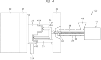
- FIG. 4 is a diagram illustrating a configuration example of a molding-product manufacturing system achieving the "HP-DSI method".
- the molding-product manufacturing system 100 has a mold-closing apparatus 30 attached to a movable platen 31 that can be moved.
- This mold-closing apparatus 30 is configured to be able to variably control a distance between the movable platen 31 and a fixed platen 35.
- a movable mold 32 and a fixed mold 33 can be placed between the movable platen 31 and the fixed platen 35.
- the mold-closing apparatus 30 when the distance between the movable platen 31 and the fixed platen 35 is variably controlled by the mold-closing apparatus 30, it is possible to shorten a distance between the movable mold 32 and the fixed mold 33 to provide the "mold-closing" state or lengthen the distance between the movable mold 32 and the fixed mold 33 to provide the "mold-opening" state.
- a sealed space is formed between the movable mold 32 and the fixed mold 33.
- Pouring the resin into this sealed space forms the partial molding product.
- two sealed spaces are formed at positions different from each other. For example, pouring the resin into one sealed space forms a partial molding product 45A, and pouring the resin into the other sealed space forms a partial molding product 45B.
- a slide mechanism 32A is attached to the movable mold 32.
- This slide mechanism 32A is configured to be able to slide a position of the movable mold 32 with respect to the fixed mold 33.
- a hot runner manifold (in-mold flow path) 34 is formed inside the fixed mold 33. By making flow of the resin through this hot runner manifold 34, the resin is injected into the two sealed spaces formed when the state between the movable mold 32 and the fixed mold 33 is the "mold-closing" state.
- an injection apparatus 41 for extruding the resin is connected to the fixed platen 35.
- the resin extruded from the injection apparatus 41 is made to flow through the fixed platen 35 into the hot runner manifold 34 formed in the fixed mold 33.
- This injection apparatus 41 has a hopper 40 for containing a resin raw material and a cylinder (barrel) 38. And, when the resin raw material is put into the hopper 40, this resin raw material is kneaded by a rotatable screw 37 placed inside the cylinder 38. At this time, a heater 39 is placed around the cylinder 38. The resin raw material put into the cylinder 38 is kneaded by the screw 37 while being heated by the heater 39 to become the molten resin. Note that a screw head backflow prevention ring 36 is provided inside the cylinder 38 to prevent backflow of the molten resin at the time of forward movement of the screw 37 (at the time of injection).
- the movable mold 32 and the fixed mold 33 are placed between the movable platen 31 and the fixed platen 35. Then, by moving the movable platen 31 be close to the fixed platen 35 by the mold-closing apparatus 30, the state between the movable mold 32 and the fixed platen 33 is made to be the "mold-closing" state. As illustrated in FIG. 4 , this forms the two sealed spaces between the movable mold 32 and the fixed mold 33.
- the resin raw material is injected from the hopper 40 of the injection apparatus 41 into the cylinder 38, and the resin raw material is kneaded by the screw 37 placed inside the cylinder 38 while the injected resin raw material is being heated by the heater 39 placed around the cylinder 38.
- the resin raw material becomes the molten resin.
- This molten resin is extruded from the inside of the cylinder 38.
- the extruded molten resin is injected via the hot runner manifold 34 formed in the fixed mold 33 into each of the two sealed spaces formed between the movable mold 32 and the fixed mold 33.
- the molten resin solidifies in the one sealed space to form the partial molding product 45A
- the molten resin in the other sealed space solidifies to form the partial molding product 45B.
- the state between the movable mold 32 and the fixed mold 33 is made to be the "mold-opening" state.
- the movable mold 32 is slid with respect to the fixed mold 33 by the slide mechanism 32A. In this manner, the partial molding product 45B is placed at a position facing the partial molding product 45A.
- a heater 42 is inserted between the partial molding product 45A and the slid partial molding product 45B. That is, the heater 42 is inserted into a cavity formed between the fixed mold 33 and the slid movable mold 32. Then, by the heat supplied from the heated heater 42, a portion that becomes the joint region between the partial molding product 45A and the partial molding product 45B is heated and melted.
- the movable platen 31 is moved to be close to the fixed platen 35 by the mold-closing apparatus 30, and therefore, the state between the movable mold 32 and the fixed mold 33 is made to be the "mold-closing" state.
- a pressure is applied to the portion that becomes the melted joint region between the partial molding product 45A and the partial molding product 45B to weld the partial molding product 45A and the partial molding product 45B.
- the "HP-DSI method” of manufacturing the unified molding product 45 is achieved by sliding the movable mold 32 with respect to the fixed mold 33 and then partially melting and bonding the partial molding product 45A and the partial molding product 45B by the heat supplied from the heater 42.
- Such an "HP-DSI method” is superior to the “DSI method” in that the sufficient bonding strength can be provided because the sufficient heat quantity can be supplied to, and the pressure can be applied to the joint region between the partial molding product 45A and the partial molding product 45B.
- the partial molding product 45A is formed in the one sealed space of the two sealed spaces formed between the movable mold 32 and the fixed mold 33, and the partial molding product 45B is formed in the other sealed space.
- the unified molding product 45 is manufactured by sliding the partial molding product 45B without removing the partial molding product 45A formed in the one sealed space and the partial molding product 45B formed in the other sealed space, and then causing the heater 42 to melt and bond the joint region between the partial molding product 45A and the partial molding product 45B. That is, in the "HP-DSI method", from a first process to a last process, the partial molding product 45A and the partial molding product 45B are processed without being removed from between the movable mold 32 and the fixed mold 33.
- the "HP-DSI method” in which the partial molding product 45A and the partial molding product 45B are processed from the first process to the last process without being removed from between the movable mold 32 and the fixed mold 33 has a risk of the shrinkage of the synthetic resin in a middle of the processes to detach the partial molding product 45A and the partial molding product 45B.
- the unified molding product 50 cannot be manufactured. Accordingly, the first room for improvement in the "HP-DSI method” is that the partial molding product 45A and the partial molding product 45B are easily detached by the shrinkage of the resin.
- the unified molding product 45 is manufactured by combining the partial molding product 45A and the partial molding product 45B.
- this unified molding product 45 has a large size, it also becomes necessary to increase a size of the molding-product manufacturing system 100 achieving the "HP-DSI method".
- the "HP-DSI method” it is necessary to provide the slide mechanism 32A that slides the movable mold 32 with respect to the fixed mold 33. Therefore, the larger size of the unified molding product 45 makes it necessary to increase the size of the slide mechanism 32A, which means that this is directly connected to increase in the size of the molding-product manufacturing system 100.
- the second room for improvement in the "HP-DSI method" is that due to the increase in the size of the unified molding product 45, it is also necessary to increase the sizes of not only the movable mold 32 itself and the fixed mold 33 itself but also the slide mechanism 32A, and, as a result, this easily leads to increase in the size of the molding-product manufacturing system 100 including these components.
- the technical idea of the present embodiment is achieved by a technique called a "Hot Plate-Injection Welding Mold” method.
- the “hot plate-injection welding mold method” is hereinafter referred to as an “HP-IWM method", and this "HP-IWM method” will be described below.
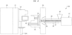
- FIG. 7 is a diagram schematically illustrating the "HP-IWM" system.
- the "HP-IWM" system 150 includes an injection molding apparatus 160, an injection molding apparatus 170, an extraction apparatus 160A, an extraction apparatus 170A, a conveyor 160B, a conveyor 170B, a robot arm 180, a molding-product manufacturing apparatus 200, and a conveyor 190.
- the injection molding apparatus 160 is configured to manufacture a partial molding product 50A.
- the partial molding product 50A manufactured by the injection molding apparatus 160 is extracted from the injection molding apparatus 160 by the extraction apparatus 160A, and is transported by the conveyor 160B.
- the injection molding apparatus 170 is configured to manufacture a partial molding product 50B.
- the partial molding product 50B manufactured by the injection molding apparatus 170 is extracted from the injection molding apparatus 170 by the extraction apparatus 170A, and is transported by the conveyor 170B.
- the robot arm 180 is configured to transport the partial molding product 50A transported by the conveyor 160B, to the molding-product manufacturing apparatus 200, and to transport the partial molding product 50B transported by the conveyor 170B, to the molding-product manufacturing apparatus 200.
- the molding-product manufacturing apparatus 200 is configured to manufacture the unified molding product 50 by fitting the partial molding product 50A and the partial molding product 50B transported by the robot arm 180 into molds, respectively, and partially melting and bonding the partial molding product 50A and the partial molding product 50B by applying heat supplied from the heater to the partial molding product 50A and the partial molding product 50B fitted in the molds.
- the robot arm 180 further has a function to transport the unified molding product 50 manufactured by the molding-product manufacturing apparatus 200 from the molding-product manufacturing apparatus 200 to the conveyor 190.
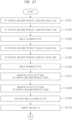
- FIG. 8 is a flowchart for explaining the overview of the operation of the "HP-IWM" system.
- the molded partial molding product 50A is extracted from the injection molding apparatus 160 by the extraction apparatus 160A (S12). Then, the partial molding product 50A extracted by the extraction apparatus 160A is transported by the conveyor 160B (S13).
- the molded partial molding product 50B is extracted from the injection molding apparatus 170 by the extraction apparatus 170A (S22). Then, the partial molding product 50B extracted by the extraction apparatus 170A is transported by the conveyor 170B
- the partial molding product 50A transported by the conveyor 160B is delivered to the molding-product manufacturing apparatus 200 by the robot arm 180, and the partial molding product 50B transported by the conveyor 170B is also delivered to the molding-product manufacturing apparatus 200 by the robot arm 180.
- the partial molding product 50A and the partially molded 50B are fitted into the molds (S31).
- a portion that becomes the joint region of each of the partial molding product 50A and partial molding product 50B fitted in the molds is heated by the heater (S32).
- the portion that becomes the joint region of each of the partial molding product 50A and partial molding product 50B is melted.
- the molding-product manufacturing apparatus 200 manufactures the unified molding product 50 by welding the melted portions (S33) to bond the partial molding product 50A and partial molding product 50B.
- the unified molding product 50 manufactured by the molding-product manufacturing apparatus 200 is transported to the conveyor 190 by the robot arm 180.
- the unified molding product 50 can be manufactured.
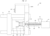
- FIG. 9 is a diagram illustrating configurations of main parts of the injection molding apparatuses 160 and 170.
- the injection molding apparatus 160 includes the movable platen 52 and the fixed platen 53 that are connected to a tie bar 51, and the movable platen 52 connected to the tie bar 51 is configured to be movable.
- a movable mold 54 and a fixed mold 55 can be placed between the movable platen 52 and the fixed platen 53.
- a sealed space is formed between the movable mold 54 and the fixed mold 55. Pouring the resin into this sealed space forms the partial molding product 50A.
- a hot runner manifold (in-mold flow path) 56 is formed inside the fixed mold 55. By making a flow of the resin through this hot runner manifold 56, the resin can be injected into the sealed space formed when the state between the movable mold 54 and the fixed mold 55 is made to be the "mold-closing" state.
- the injection apparatus 41 is connected to the fixed mold 55.
- the injection apparatus 41 has functions to rotate and move a screw forward and backward, and can melt and plasticize, weigh, and inject the resin.
- the resin injected from the injection apparatus 41 is made to flow into the hot runner manifold 56 formed inside the fixed mold 55.
- This injection apparatus 41 has a hopper 61 for containing a resin raw material and a cylinder (barrel) 59. And, when the resin raw material is put into the hopper 61, this resin raw material is kneaded by a rotatable screw 58 placed inside the cylinder 59. At this time, a heater 60 is placed around the cylinder 59. The resin raw material put into the cylinder 59 is kneaded by the screw 58 while being heated by the heater 60 to become the molten resin. Note that a screw head backflow prevention ring 57 is provided inside the cylinder 59 to prevent backflow of the molten resin at the time of forward movement of the screw 58 (at the time of injection).
- an extraction apparatus 160A for extracting the manufactured partial molding product 50A is attached to the injection molding apparatus 160, and a chuck 62 for sucking the partial molding product 50A is provided to this extraction apparatus 160A.
- the movable mold 54 and the fixed mold 55 are placed between the movable platen 52 and the fixed platen 53. Then, in the injection molding apparatus 160, the state between the movable mold 54 and fixed mold 55 is made to be the "mold-closing" state by moving the movable platen 52 to be close to the fixed platen 53. In this manner, as illustrated in FIG. 9 , the sealed space is formed between the movable mold 54 and the fixed mold 55.
- the resin raw material is injected from the hopper 61 of the injection apparatus 41 into the cylinder 59, and the resin raw material is kneaded by the screw 58 placed inside the cylinder 59 while the injected resin raw material is being heated by the heater 60 placed around the cylinder 59.
- the resin raw material becomes the molten resin.
- This molten resin is weighed in the cylinder 59 by the backward movement of the screw, and is injected by the forward movement of the screw.
- the injected molten resin is injected via the hot runner manifold 56 formed in the fixed mold 55 into the sealed space formed between the movable mold 54 and the fixed mold 55. As a result, the molten resin solidifies in the sealed space to form the partial molding product 50A.
- the state between the movable mold 54 and the fixed mold 55 is made to be the "mold-opening" state by moving the movable platen 52 to be away from the fixed platen 53.
- the partial molding product 50A is sucked by the chuck 62 provided in the extraction apparatus 160A.
- the partial molding product 50A sucked by the chuck 62 is placed on and transported by, for example, the conveyor 160B illustrated in FIG. 7 .
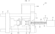
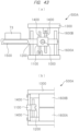
- FIG. 12 is a schematic diagram illustrating an appearance configuration of the molding-product manufacturing apparatus 200.
- the molding-product manufacturing apparatus 200 can be provided as a dedicated apparatus, and can also be provided by, for example, modifying a general-purpose press machine. Specifically, the molding-product manufacturing apparatus 200 can be achieved by mounting a mold, a heater, a heater slide mechanism, and a heater slide controller, onto the general-purpose press machine. This molding-product manufacturing apparatus 200 is configured to manufacture the unified molding product by partially melting and bonding two partial molding products by heat supplied from the heater, and has the following configuration.
- the molding-product manufacturing apparatus 200 incudes a mold 70A, a mold 70B, a contact/contactless controller 71, a heater 72, a heater slide mechanism 73, and a heater slide controller 74.
- the mold 70A is configured to, for example, fit a partial molding product 250A manufactured by one of the injection apparatuses therein, and is fixed to a stage. Therefore, the mold 70A can be said to be a fixed mold that is fixed to the stage. This stage functions as a mold mounting portion 75A for mounting the mold 70A.
- the mold 70A has a concave portion formed therein, and the partial molding product 250A is fitted into this concave portion.
- the mold 70B is configured to, for example, fit a partial molding product 250B manufactured by the other of the injection apparatuses therein. And, the mold 70B is placed at a position facing the mold 70A and is movable so as to change a distance between the fixed mold 70A and the mold 70B. Therefore, the mold 70B can be said to be a movable mold that can be moved.
- This mold 70B is loaded on a mold mounting portion 75B.
- this mold 70B has a concave portion formed therein, and the partial molding product 250B is fitted into this concave portion.
- the contact/contactless controller 71 is configured to control contact/contactless between the partial molding product 250A fitted in the mold 70A and the partial molding product 250B fitted in the mold 70B. Specifically, the contact/contactless controller 71 controls the contact/contactless state between the partial molding product 250A and the partial molding product 250B, by controlling the state between the mold 70A and the mold 70B to be the "mold-closing"/"mold-opening" state. For example, the contact/contactless controller 71 is configured to be able to control the state between the mold 70A and the mold 70B to be the "mold-closing"/"mold-opening" state by controlling the movement of the mold 70B. This contact/contactless controller 71 can be said to be a variable controller that variably controls a distance between the mold mounting portion 75A and the mold mounting portion 75B.
- the heater 72 is configured to be able to be inserted between the partial molding product 250A fitted in the mold 70A and the partial molding product 250B fitted in the mold 70B, and is configured to be able to heat the portion that becomes the joint region between the partial molding product 250A and the partial molding product 250B while being inserted between the partial molding product 250A and the partial molding product 250B.
- the heater 72 is configured to be movable to be inserted in a cavity formed between the mold 70A in which the partial molding product 250A is placed and the mold 70B in which the partial molding product 250B is placed, and is configured to be able to heat the portion that becomes the joint region between the partial molding product 250A and the partial molding product 250B while being inserted in the cavity.
- the heater slide mechanism 73 is fixed to any of the mold 70A, the mold 70B, the mold mounting portion 75A and the mold mounting portion 75B, and is configured to slide the heater 72 in order to insert the heater 72 between the partial molding product 250A and the partial molding product 250B or to evacuate the heater 72 from between the partial molding product 250A and the partial molding product 250B. That is, the heater slide mechanism 73 is configured to allow the heater 72 to slide between the insertion position and the evacuation position. The heater slide mechanism 73 is controlled by the heater slide controller 74.
- the mold 70A is placed on a stage 75A, and the partial molding product (first workpiece) 250A is fitted in this mold 70A.
- the mold 70B is placed at a position facing the mold 70A, and the partial molding product (second workpiece) 250B is fitted in this mold 70B.
- the contact/contactless controller 71 is configured to control the movement of the mold 70B by using movement of a stage 75B. That is, the contact/contactless controller 71 is configured to control the distance or the contact/contactless state between the partial molding product 250A fitted in the mold 70A and the partial molding product 250B fitted in the mold 70B, by controlling the movement of the mold 70B.
- the contact/contactless controller 71 has a function to control the distance or the state between the mold 70A and the mold 70B to be the "mold-closing"/"mold-opening" state.
- the molding-product manufacturing apparatus 200 includes the heater 72.
- This heater 72 is connected to the heater slide mechanism 73, and can be slid by the heater slide mechanism 73 in an arrow direction (horizontal direction) of FIG. 12 .
- the heater slide controller 74 is configured to control temperatures or outputs of the heater slide mechanism 73 and the heater. By the heater slide controller 74 controlling the heater slide mechanism 73, the heater 72 is inserted between the partial molding product 250A and the partial molding product 250B or is evacuated from between the partial molding product 250A and the partial molding product 250B.
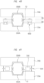
- FIG. 13(a) and FIG. 13(b) are diagram viewed from above FIG. 12 , and is a plan view schematically illustrating movement of the heater 72.
- the heater 72 is configured to be slidable between the insertion portion ( FIG. 13(a) ) that planarly overlaps the mold 70B and the evacuation position ( FIG. 13(b) ) that does not planarly overlap the mold 70B.
- FIG. 13 (a) if the heater 72 is placed at the insertion portion that planarly overlaps the mold 70B, a heating position by the heater 72 overlaps a welding region of the partial molding product 250B and the partial molding product 250A. This allows the heater 72 to heat the portion that becomes the joint region between the partial molding product 250A and the partial molding product 250B.
- the molding-product manufacturing apparatus 200 is configured as described above.
- the heater 72 used in the "HP-IWM method" may be made of a contactless heater or a contact heater.
- the contactless heater may include a carbon heater or a halogen heater.
- a type of the contactless heater is not limited if it can irradiate a partial molding product with infrared rays, near-infrared rays, or the like to heat the partial molding product without contact.
- the contact heater a heating plate can be exemplified.
- the heating plate is a member capable of, for example, heating the welded portion, such as a member made of a plate made of metal such as iron, aluminum, brass, or copper heated by a cartridge heater, a ceramic heater in which a heating element is sandwiched between ceramics such as alumina or silicon nitride to be insulated, a film-like heater in which a heating element is sandwiched by heat-resistant films to be insulated or others.
- the contactless heater has an advantage of easier temperature adjustment than the contactless heater.
- Both of the contactless heater and the contact heater may have a shape that makes it possible to heat an entire projection plane of the partial molding product or may have a shape that makes it possible to selectively heat only the welded portion of the partial molding product.
- resin in the non-heated portion does not melt, and that portion is not joined.
- the heater is required to have a function to adjust its shape and output characteristics, or the like, to uniformly heat the welded portion.
- the operation differs depending on whether the heater 72 is the contactless heater or the contact heater. For this reason, the operation in the case of the heater 72 made of the contactless heater will be described first, and then, the operation in the case of the heater 72 made of the contact heater will be described.
- FIG. 14 and FIG. 15 are flowcharts each for explaining the operation of the molding-product manufacturing apparatus.
- the partial molding product 250A is fitted in the mold 70A (S101 of FIG. 14 ), and the partial molding product 250B is fitted in the mold 70B (S102 of FIG. 14 ). Thereafter, as illustrated in FIG. 17 , the mold 70B is moved downward by the control of the contact/contactless controller 71 to provide the "mold-closing" state (S103 of FIG. 14 ) in which the mold 70A and the mold 70B are brought to a position where the joint portions of the partial molding product 250A and the partial molding product 250B are adhered.
- the mold 70B is moved downward by the control of the contact/contactless controller 71 to provide the "mold-closing" state (S103 of FIG. 14 ) in which the mold 70A and the mold 70B are brought to a position where the joint portions of the partial molding product 250A and the partial molding product 250B are adhered.
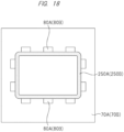
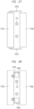
- FIG. 18 is a plan view schematically illustrating a state in which the partial molding product fitted in the mold is fixed by a plurality of chucks.
- the partial molding product 250A fitted in the mold 70A is fixed by a plurality of chucks 80A (S104 of FIG. 14 ).
- the partial molding product 250B fitted in the mold 70B is fixed by a plurality of chucks 80B (S105 of FIG. 14 ).
- the mold 70A has the plurality of chucks 80A fixing the partial molding product 250A.
- the mold 70B has the plurality of chucks 80B fixing the partial molding product 250B.
- the number of chucks can be determined appropriately by a size of the molding product.
- the fixing of the partial molding product 250A (S104) and the fixing of the partial molding product 250B (S105) may be performed simultaneously.
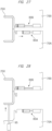
- FIG. 19 and FIG. 20 are diagrams each illustrating an example of a method of fixing the partial molding product by the chuck.
- a flange 90 is provided at a tip of the partial molding product 250A fitted in the mold 70A.
- the chuck 80A is made of a partial core 81 and an air cylinder 82.
- the partial molding product 250A can be fixed by the chuck 80A.
- FIG. 21 and FIG. 22 are diagrams each illustrating another example of the method of fixing the partial molding product 250A by the chuck 80A and the method of fixing the partial molding product 250B by the chuck 80B.
- the chuck 80A has a partial core 83A and an air cylinder 84A, and the partial core 83A and the air cylinder 84A are connected.
- the chuck 80B has a partial core 83B and an air cylinder 84B, and the partial core 83B and the air cylinder 84B are connected.
- a tip of the partial core 83A and a tip of the partial core 83B have a "saw blade shape" that is easy to be pressed and easy to cause detachment.
- the partial molding product 250A can be fixed by the chuck 80A.
- the partial core 83B is pressed against an end of the partial molding product 250B by the extrusion force based on the air cylinder 84B, the partial molding product 250B can be fixed by the chuck 80B.
- the air cylinder 84A or 84B may be an oil hydraulic cylinder.
- the partial cores 83A and 83B may be pressed against the ends of the partial molding products 250a and 250B by elastic force based on a spring.
- the partial cores 83A and 83B may be moved by a motor.
- the mold 70B is moved upward by the control of the contact/contactless controller 71 to provide the "mold-opening" state as the state between the mold 70A and the mold 70B (S106 of FIG. 14 ).
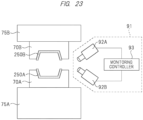
- the fitting state of the partial molding product 250A fitted in the mold 70A is monitored by a monitor 91 (S107 of FIG. 14 ), and the fitting state of the partial molding product 250B fitted in the mold 70B is monitored by the monitor 91 (S108 of FIG. 14 ).
- the monitor 91 has an imager 92A, an imager 92B, and a monitoring controller 93.
- the imager 92A is configured to capture an image of the fitting state of the partial molding product 250A
- the imager 92B is configured to capture an image of the fitting state of the partial molding product 250B.
- the monitoring controller 93 is configured to monitor whether or not the fitting state of the partial molding product 250A is good, based on the image captured by the imager 92A, and is configured to monitor whether or not the fitting state of the partial molding product 250B is good, based on the image captured by the imager 92B.
- a commercially-available camera for monitoring the mold state can be used as the imager 92A and the imager 92B.
- the states of the partial molding products 250A and 250B may be monitored by either one of the imagers 92A and 92B, or the states of the partial molding product 250A and the partial molding product 250B may be individually monitored by a plurality of the imagers.
- the monitor 91 determines that the fitting state of the partial molding product 250A and the fitting state of the partial molding product 250B are good, the operation of the molding-product manufacturing apparatus 200 is continued. In contrast, if the monitor 91 determines that at least either one of the fitting state of the partial molding product 250A or the fitting state of the partial molding product 250B is not good, it is possible to take a measure to stop the operation of the molding-product manufacturing apparatus 200. Consequently, it can be expected that production of defective items or damage on the molds can be prevented.
- the mold 70B is slightly moved downward by the control of the contact/contactless controller 71 to provide a halfway "mold-closing" state as the state between the mold 70A and the mold 70B (S109 of FIG. 14 ).
- the heater slide mechanism 73 is controlled by the heater slide controller 74 to slide the heater 72 and insert the heater 72 to the gap between the partial molding product 250A and the partial molding product 250B (S110 of FIG. 14 ).
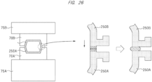
- the heater 72 is heated (Sill of FIG. 14 ). As a result, the heat supplied from the heater 72 melts the portion that becomes the joint region between the partial molding product 250A and the partial molding product 250B. Thereafter, as illustrated in FIG. 25 , the heater slide mechanism 73 is controlled by the heater slide controller 74 to slide the heater 72 and evacuate the heater 72 from between the partial molding product 250A and the partial molding product 250B (S112 of FIG. 15 ) .
- the mold 70B is moved downward by the control of the contact/contactless controller 71 to provide the "mold-closing" state as the complete state between the mold 70A and the mold 70B (S113 of FIG. 15 ).
- the pressing at a predetermined pressure or the pusing at a predetermined amount is performed for a predetermined period of time measured by a timer.
- the molten resin is flown out to weld the joint portion between the partial molding product 250A and the partial molding product 250B.
- the partial molding product 250A and the partial molding product 250B are unified to be the unified molding product 50.
- the fixing of the unified molding product 50 by the chuck 80A is released (S114 of FIG. 15 ).
- the mold 70B is moved upward by the control of the contact/contactless controller 71 to provide the "mold-opening" state as the state between the mold 70A and the mold 70B and cause an oil-hydraulically projecting pin 95 to push up the unified molding product 250 (S115 of FIG. 15 ).
- the fixing of the unified molding product 50 by the chuck 80B is released (S116 of FIG. 15 ).
- the unified molding product 250 is finally extracted (S117 of FIG. 15 ).
- an order of removing the chucks 80A and 80B is not limited to this.
- the fixing by the chuck 80A is first released, the fixing by the chuck 80B may be released first by switching side A and side B.
- the unified molding product 250 can be manufactured by the operation of the molding-product manufacturing apparatus 200 according to the present embodiment.
- FIG. 31 and FIG. 32 are flowcharts each explaining the operation of the molding-product manufacturing apparatus.
- FIG. 31 and FIG. 32 are substantially similar to the flowcharts illustrated in FIG. 14 and FIG. 15 , and thus, different points will be mainly described.
- step S101 to step S110 are similar.
- the heater 72 is inserted between the partial molding product 250A and the partial molding product 250B (S110 of FIG. 31 ). At this time, there is a gap between the heater 72 and the partial molding product 250A/partial molding product 250B. In other words, the heater 72 is in a contactless state with the partial molding product 250A and the partial molding product 250B.
- the mold 70B is moved downward by the control of the contact/contactless portion 71 to provide the "mold-closing" state as the state between the mold 70A and the mold 70B.
- the heater 72 is brought into contact with and sandwiched between the partial molding product 250A and the partial molding product 250B.
- the "mold-closing" state at this time is adjusted to reduce the pressing force to prevent the heater 72 from being damaged.
- the heater 72 is heated while being in contact with the partial molding product 250A and the partial molding product 250B. In this manner, the portion that becomes the joint region between the partial molding product 250A and the partial molding product 250B is melted (S201 of FIG. 32 ).
- the mold 70B is moved upward by the control of the contact/contactless controller 71 to provide the "mold-opening" state as the state between the mold 70A and the mold 70B (S202 of FIG. 3 ).
- the heater slide mechanism 73 is controlled by the heater slide controller 74 to slide the heater 72 and evacuate the heater 72 from between the partial molding product 250A and the partial molding product 250B (S112 of FIG. 32 ).
- the unified molding product 250 can be manufactured by the operation of the molding-product manufacturing apparatus 200 according to the present embodiment.
- a first feature point of the present embodiment is that there is a step of fitting the partial molding product to the mold in the technique of manufacturing the unified molding product by using the heat supplied from the heater to partially melt and bond two partial molding products. Consequently, even if the resin that configures the partial molding product shrinks, it is possible to prevent the detachment of the partial molding product from the mold.
- the partial molding product is processed without being removed from the mold during the first step to the last step.
- the synthetic resin that configures the partial molding product has the property of shrinking. For this reason, if the partial molding product is processed without being removed from the mold during the first step to the last step, the synthetic resin may shrink in the middle of the steps, and the partial molding product may be detached from the mold.
- the partial molding product manufactured by another apparatus is fitted in the mold.
- the mold can be designed in consideration of the shrinkage of the resin that configures the partial molding product, and therefore, the possibility of the detachment of the partial molding product from the mold can be reduced. As a result, according to the present embodiment, it is possible to improve a manufacturing yield of the unified molding products.
- the present embodiment adopts a further contrivance for suppressing the detachment of the partial molding product from the mold due to the shrinkage of the synthetic resin that configures the partial molding product.
- a second feature point of the present embodiment is that, for example, the chuck for fixing the partial molding product fitted in the mold is provided as illustrated in FIG. 18 to FIG. 22 .
- the chuck for fixing the partial molding product fitted in the mold is provided as illustrated in FIG. 18 to FIG. 22 .
- the present embodiment even if the partial molding product is almost detached from the mold, it is possible to effectively prevent the detachment of the partial molding product from the mold because the partial molding product is fixed by the chuck.
- the second feature point of the present embodiment since the possibility of the detachment of the partial molding product from the mold can be reduced, it is possible to further improve the manufacturing yield of the unified molding products.
- a third feature point of the present embodiment is that, for example, the monitor configured to monitor the fitting state of the partial molding product is provided as illustrated in FIG. 23 . Because of this configuration, the detachment of the partial molding product from the mold can be detected by the monitor even if happed. And, if the monitor detects anomaly such as a lift of the partial molding product, it is also possible to stop the manufacturing line. Therefore, according to the third feature point of the present embodiment, the production of defective items can be prevented before happening, and therefore, it is possible to further improve the manufacturing yield of the unified molding products even in terms of this point.
- the technical idea of the present embodiment is a technical idea of manufacturing the unified molding product by melting and bonding the portion that becomes the joint region of each of the plurality of partial molding products by using heat supplied from the heater. And, in the molding-product manufacturing apparatus that embodies this technical idea, the heater plays an important role to improve performance of the molding-product manufacturing apparatus.
- the various contrivance points related to the heater will be described below.
- the technical idea of the present embodiment described above is mainly an idea related to the "HP-IWM method".
- the contrivance points related to the heater described below are widely applicable to methods using the heater for manufacturing the molding product.
- the various contrivance points related to the heater are widely applicable to not only the molding-product manufacturing apparatus achieving the "HP-IWM method” but also the molding-product manufacturing apparatus achieving the "HP-DSI method”.
- the following description will be made particularly in assumption of the molding-product manufacturing apparatus achieving the "HP-IWM method”.
- FIG. 33 is a diagram for explaining room for improvement.
- the portion that becomes the joint region between the partial molding product 250A fitted in the mold 70A and the partial molding product 250B fitted in the mold 70B is melted by being heated by the heater 72 inserted between the mold 70A and the mold 70B. Thereafter, the heater 72 becomes an obstacle for the welding of the melted portion, and therefore, for example, the heater 72 is evacuated to outside of the mold 70A and the mold 70B as illustrated in FIG. 33 .
- the stroke L1 illustrated in FIG. 33 in order to reliably evacuate the heater 72 to a position where the heater does not come into contact with the mold 70A and the mold 70B, it is necessary to make a stroke L1 illustrated in FIG. 33 longer.
- the stroke L1 if the stroke L1 is long, a total length of the apparatus is long, and this leads to increase in a size of the molding-product manufacturing apparatus.
- the long stroke L1 means long cycle time for sliding the heater 72 between the insertion portion and the evacuation position, and this leads to decrease in throughput.
- a sliding distance of the heater 72 becomes long, and misalignment (deflection) of the support portion supporting the heater 72 becomes large. This means that uniform heating at the joint region by the heater 72 becomes difficult. For these reasons, it is desirable that the stroke for sliding the heater 72 be as short as possible.
- the present embodiment adopts contrivance points for shortening the stroke for sliding the heater 72 as much as possible. This contrivance points will be described below.
- FIG. 34 is a diagram for explaining a first contrivance point.
- the mold 70B is provided with, for example, a notch portion 300.
- This notch portion 300 functions as a standby place (evacuation place) for the heater 72. That is, when the heater 72 moves to the standby place outside of the cavity formed by the mold 70A and the mold 70B, the heater 72 and the notch portion 300 overlap in plan view. In this manner, the first contrivance point is to provide the mold 70B with the notch portion 300 to be the evacuation place of the heater 72.
- the notch portion 300 may be provided to not the mold 70B but the mold 70A, or may be provided to both the mold 70B and the mold 70A.
- a stroke L2 for sliding the heater 72 is made shorter than the stroke L1 illustrated in FIG. 33 showing the case without the notch portion 300.
- the stroke L2 is shortened, and as a result, the total length of the apparatus can be shortened, and therefore, the increase in the size of the molding-product manufacturing apparatus can be suppressed.
- the insertion portion and the evacuation position of the heater 72 become closer to each other, and as a result, the cycle time for sliding the heater 72 to reciprocate can be reduced. This means that the throughput is improved.
- the shorter time for sliding the heater 72 from the insertion position to the evacuation position means that time taken from the evacuation of the heater 72 to the welding of the melted region is short.
- the short time taken until the welding of the melted region means that it is possible to suppress a temperature drop at the melted region. As a result, the melted region can be welded while high temperature is maintained. Therefore, according to the first contrivance point, it is possible to improve the bonding reliability of the melted region.
- the length of the support portion (for example, a support arm) supporting the heater 72 can be shortened, the misalignment (deflection) of the support portion can be suppressed. As a result, according to the first contrivance point, it is possible to achieve the uniform heating at the portion that becomes the joint region.
- the first contrivance point of providing the notch portion 300 in the mold 70B the time for sliding the heater 72 can be reduced.
- the remarkable effects such as (1) the suppression of the increase in the size of the molding-product manufacturing apparatus, (2) the improvement of the manufacturing efficiency of the unified molding product through the improved throughput, and (3) the improvement of the bonding reliability of the bonding region because of the suppression of the temperature drop at the melted region and the achievement of the uniform heating, the remarkable effects being difficult to be achieved by the prior-art technique.
- the first contrivance point has an exceptional technical significance in that a large effect can be achieved without increasing a cost.
- the second contrivance point is a contrivance point for the room of improvement appearing in the "horizontal configuration".
- the room for improvement particularly appearing in the "horizontal configuration” will be described below.
- FIG. 35 is a diagram schematically illustrating the "horizontal configuration”.
- the mold 70A and the mold 70B are placed to face each other in the horizontal direction.
- the heater 72 is inserted in a gap between the mold 70A and the mold 70B. If the heater 72 is heated in this state, cold air flows into the gap from a lower side, and the flowed cold air is warmed by the heater 72. The warmed air flows toward an upper side of the gap. In this manner, by the heating of the heater 72 inserted in the gap between the mold 70A and the mold 70B, convection is generated in the air existing in the gap, and as a result, a temperature difference is caused between the lower side and the upper side of the gap. That is, a temperature distribution is generated in the gap.
- the uniform heating is not possible, and as a result, this adversely affects the welding of the melted region. Therefore, even in the heating of the heater 72 inserted in the gap between the mold 70A and the mold 70B, the small temperature difference in the gap is desirable. That is, it is desirable to suppress the air convection that causes non-uniformity of the temperature in the gap.
- the present embodiment adopts a contrivance to improve temperature uniformity in the gap between the mold 70A and the mold 70B. This contrivance point will be described below.
- FIG. 36 is a diagram for explaining a first solution.
- a swinging mechanism 400 is connected to the heater 72 that is insertable into the gap between the mold 70A and the mold 70B.
- This swinging mechanism 400 includes, for example, a forward/backward movement mechanism 410 configured to move the heater in a forward or backward direction; a rotatable motor 420; and an eccentric cam 430 attached to the motor.
- the heater 72 connected to the swinging mechanism 400 is capable of a swing action (swinging movement).
- the first solution is to connect the swinging mechanism 400 with the heater 72 to perform the swinging action to the heater 72 inserted in the gap between the mold 70A and the mold 70B.
- the air existing in the gap is agitated by the heater 72 under the swinging action, and therefore, it is possible to suppress the non-uniformity of the temperature due to the convection.
- the present embodiment adopts a further contrivance to improve the temperature uniformity in the gap between the mold 70A and the mold 70B. This contrivance point will be described below.
- a basic idea of the second solution is an idea of improving the temperature uniformity in the gap by providing a convection suppression member for suppressing the air convection that causes the temperature non-uniformity in the gap between the mold 70A and the mold 70B.
- FIG. 37 is a diagram illustrating a first specific configuration example.
- the mold 70A is provided with a cover 440 to cover the upper side of the gap, and a cover 450 to cover the lower side of the gap.
- the cover 450 suppresses inflow of the cold air from the lower side of the gap
- the cover 440 suppresses outflow of the warm air from the upper side of the gap.
- the cover 440 and the cover 450 suppress the air convection due to the heat generated from the heater 72 inserted in the gap. That is, the cover 440 and the cover 450 act as the convection suppression member for suppressing the convection due to the heat supplied from the heater.
- FIG. 38 is a diagram illustrating a second specific configuration example.
- an outer frame body 460 to be placed outside the heater 72 is inserted together with the heater 72 into the gap.
- the second specific configuration example is configured so that a slide unit being a unified structure made of the heater 72 and the outer frame body 460 placed outside the heater 72 is slid by a heater slide mechanism.
- the outer frame body 460 acts as the convection suppression member for suppressing the convection due to the heat supplied from the heater.
- the attachment of the cover 440 and the cover 450 for preventing the convection to the outside of this outer frame body 460 can further enhance the effect of suppressing the convection.
- the outer frame body 460 has a function acting as the convection suppression member, this outer frame body 460 also has another function. Another function of the outer frame body 460 will be described. For example, the following advantages can be provided when the heater 72 is placed in the middle of the outer frame body 460 in a thickness direction. Specifically, when the partial molding product protrudes because of not properly being fitted in the mold or when a foreign object protrudes from the mold, the outer frame body 460 collides earlier than the heater 72. In this case, torque anomaly or the like occurs in the heater slide mechanism that slides the outer frame body 460. Therefore, the heater 72 can be protected if this torque anomaly or the like is detected to stop the apparatus. That is, the outer frame body 460 has not only the function acting as the convection suppression member but also the function of protecting the heater 72.
- the slide unit may be provided in the mold 70A or the stage 75A of the molding-product manufacturing apparatus 200, or may be provided independently outside the molding-product manufacturing apparatus 200.
- a heater position can be controlled at a location closer to the molding product.
- designing is possible without considering the influence of the misalignment (deflection) of the support portion, and this designing can shorten the distance between the parting surface of the mold 70A and the outer frame body 460 to further enhance the effect of the convection suppression member.
- the second solution based on the basic idea of providing the convection suppression member, even in the case without the swinging mechanism for swinging the heater 72, it is possible to improve the temperature uniformity in the gap between the mold 70A and the mold 70B by the simple configuration as described in the first specific configuration example or the second specific configuration example. That is, it can be said that the second solution has the exceptional technical significance in that the large effect can be provided without increasing the cost.
- the heater 72 is made of the heating plate that is the contact heater, the heater 72 needs to evenly contact both the partial molding product 250A fitted in the mold 70A and the partial molding product 250B fitted in the mold 70B. Therefore, when the state between the mold 70A and the mold 70B changes from the "mold-opening" state to the "mold-closing” state, it is desirable to maintain the heater 72 to be placed at a center position between the mold 70A and the mold 70B.
- a centering mechanism 500 is provided between the mold 70A and the mold 70B.
- This centering mechanism 500 has a connection portion 510 connected to the heater 72, a spring 520A provided on the mold 70A side, and a spring 520B provided on the mold 70B side.
- a spring constant of the spring 520A and a spring constant of the spring 520B are set to a same value.
- the heater 72 made of the heating plate can be evenly brought into contact with both the partial molding product 250A and the partial molding product 250B at the same timing and pressing force.
- the transfer of the heat between the partial molding products 250A and 250B and the heater 72 depends on the pressing pressure. Therefore, according to the third contrivance point, it is possible to uniformly heat the portion that becomes the joint region between the partial molding product 250A and the partial molding product 250B by the heater 72.
- FIG. 40 is a diagram illustrating an example of a fixing mechanism for fixing the heater 72 made of the contactless heater.
- a fixing mechanism 600 illustrated in FIG. 40 for example, a distance between the heater 72 and the mold 70A is mechanically adjusted by a shim or the like.
- the heater 72 and the mold 70B are adjusted by the control of the contact/contactless controller 71 that moves the mold 70B. That is, in the configuration illustrated in FIG. 40 , the distance ("A") between the heater 72 and the mold 70A and the distance ("B") between the heater 72 and the mold 70B are adjusted by different mechanisms from each other. As a result, in the configuration illustrated in FIG.
- the centering mechanism 500 which is the third contrivance point, as the fixing mechanism for fixing the heater 72 made of the contactless heater.
- FIG. 41 is a diagram illustrating a configuration example adopting the centering mechanism which is the third contrivance point as the fixing mechanism for fixing the heater 72 made of the contactless heater.
- FIG. 42(a) and FIG. 42(b) are diagrams each schematically illustrating operation of the centering mechanism illustrated in FIG. 41 . Note that the partial molding products 250A and 250B are omitted in FIG. 42(a) and FIG. 42(b) .
- the centering mechanism 500 is connected to a frame 700, and the heater 72 fixed to the frame 700 is placed at a center position of this frame 700.
- the centering mechanism 500 which is the third contrivance point is connected to the frame 700, it is possible to equalize a distance between the frame 700 and the mold 70A and a distance between the frame 700 and the mold 70B ( FIG. 42(a) and FIG. 42(b) ).
- the heater 72 is placed at the center position of the frame 700, the distance between the heater 72 and the partial molding product 250A fitted in the mold 70A is naturally equal to the distance between the heater 72 and the partial molding product 250A fitted in the mold 70B.
- the heater 72 is made of the contactless heater, as also described above in the second contrivance point, it is desirable in the gap between the mold 70A and the mold 70B to provide the convection suppression member for suppressing the temperature distribution due to the air convection, from a viewpoint of the uniform heating.
- the frame 700 acts as the convection suppression member. That is, the frame 700 is adopted to fix the heater 72 made of the contactless heater, and the configuration (illustrated in FIG. 41 ) in which the centering mechanism 500 which is the third contrivance point is connected to this frame 700 is adopted.
- This case can provide a remarkable effect that achieves the uniform heating on the partial molding product 250A fitted in the mold 70A and on the partial molding product 250B fitted in the mold 70B because of synergistic factors that are a factor in which the heater 72 can be placed at the center of the mold 70A and the mold 70B by the centering mechanism 500 and a factor in which the frame 700 itself acts as the convection suppression member.
- the gap between the heater 72 and the partial molding products 250A and 250B can be reduced, and besides, there is no gap where the air stays, and therefore, the convection suppression effect can be further enhanced.
- temperature of air in the frame 700 increases to decrease heat release from the partial molding products 250A and 250B to the air, the efficiency of heating is further increased.
- the centering mechanism 500 for example, the spring-type centering mechanism has been exemplified and described.
- the centering mechanism 500 is not limited to this.
- a rack-and-pinion type centering mechanism 500A as illustrated in FIG. 43(a) and FIG. 43(b) or a link-mechanism type centering mechanism 500B as illustrated in FIG. 44(a) and FIG. 44(b) can be adopted.
- FIG. 43(a) is a front view of the rack-and-pinion type centering mechanism 500A
- FIG. 43(b) is a side view of the rack-and-pinion type centering mechanism 500A.
- a gear 1000 is housed in a gearbox 1100, and the gearbox 1100 is fixed to a guide rail 1200.
- a frame 1500 including a heater and the heater slide mechanism 73 that drives the frame 1500 including the heater are connected to the guide rail 1200.
- a rack 1400 rotates the gear 1000, and the guide rail 1200, to which the frame 1500 including the heater is attached, moves to be always at a center between a mold 1600A and a mold 1600B.
- the rack-and-pinion type centering mechanism 500A it is possible to place the frame 1500 including the heater at the center position between the mold 1600A and the mold 1600B.
- FIG. 44 (a) is a plan view of the link-mechanism type centering mechanism 500B
- FIG. 44 (b) is a side view of the link-mechanism type centering mechanism 500B.
- the guide rail 1200 placed at the center of the mold is designed to be always placed at the center at the time of the opening/closing of the mold. Thus, it is possible to provide the same effect as the spring-type centering mechanism 500.
- the guide rail 1200, the heater slide mechanism 73, the gearbox 1100, the gear 1000, and the rack 1400 or the like that configure the rack-and-pinion type centering mechanism 500A, and the long link 2000A and the short link 2000B or the like that configure the link-mechanism type centering mechanism 500B need to be placed outside the mold 1600A and the mold 1600B in a planar direction so as not to interfere with the mold 1600A and the mold 1600B at the time of the "mold-closing" state (see FIG. 43(b) and FIG. 44(b) ) .
Landscapes
- Engineering & Computer Science (AREA)
- Mechanical Engineering (AREA)
- Manufacturing & Machinery (AREA)
- Physics & Mathematics (AREA)
- Health & Medical Sciences (AREA)
- Electromagnetism (AREA)
- Toxicology (AREA)
- Injection Moulding Of Plastics Or The Like (AREA)
- Moulds For Moulding Plastics Or The Like (AREA)
- Lining Or Joining Of Plastics Or The Like (AREA)
Abstract
Description
- The present invention relates to an apparatus of manufacturing a resin molding product, a method of manufacturing a resin molding product, and a mold.
-
Japanese Patent Application Laid-open Publication No. 2018-008404 - Patent Document 1:
Japanese Patent Application Laid-open Publication No. 2018-008404 - When a hollow molding product having a cavity therein is manufactured by an injection molding technique, instead of manufacturing of a unified hollow molding product, each of a plurality of partial molding products is manufactured by the injection molding technique, and then, the plurality of partial molding products are bonded to manufacture the hollow molding product in some cases.
- In this technique, the injection molding technique is also used when, for example, the plurality of partial molding products are bonded. That is, instead of using an adhesive to bond the plurality of partial molding products, injected molten resin is poured into a joint region to bond the plurality of partial molding products.
- However, the method of bonding the plurality of partial molding products by pouring the injected molten resin into the joint region is difficult in some cases to provide sufficient bonding strength due to a difference in constituent materials and crystallinity of the plurality of partial molding products, due to a small quantity of heat applied to the joint region, or the like.
- Accordingly, for example, as a technique for bonding the plurality of partial molding products, instead of using the injected molten resin, a technique for bonding the plurality of partial molding products has been developed, the technique being made by inserting a heater between the plurality of partial molding products, melting the joint region of the plurality of partial molding products by heat generated from the heater, and then, applying pressure to the melted joint region.
- In regard to this point, the technique using the heater for bonding the plurality of partial molding products is more superior in that the sufficient bonding strength can be provided, than the technique using the injected molten resin for bonding the plurality of partial molding products. However, even in the technique using the heater for manufacturing the molding product, it is still desirable to make contrivance to further improve performance.
- An apparatus of manufacturing a resin molding product according to an embodiment includes: a first mold mounting portion being capable of mounting a first mold thereon; a second mold mounting portion being capable of mounting a second mold having a notch portion thereon; and a heater being movable to be inserted in a cavity formed by the first mold and the second mold. Here, when the heater moves to outside of the cavity, the heater and the notch portion overlap in plan view.
- The apparatus of manufacturing the resin molding product according to the embodiment includes a heater swinging portion configured to swing the heater.
- The apparatus of manufacturing the resin molding product according to the embodiment includes a convection suppression member configured to suppress convection due to the heat generated from the heater inserted into the cavity.
- The apparatus of manufacturing the resin molding product according to the embodiment includes a centering mechanism capable of being attached between the first mold and the second mold that face each other when the first mold is mounted on the first mold mounting portion and the second mold is mounted on the second mounting portion, the centering mechanism being capable of adjusting a position of placement of the heater inserted into the cavity to a center position between the first mold and the second mold.
- The apparatus of manufacturing the resin molding product according to the embodiment includes a first monitor configured to be able to monitor a state of placement of a first portion and a second monitor configured to be able to monitor a state of placement of a second portion.
- A method of manufacturing a resin molding product according to an embodiment includes: a step of placing a first portion configuring a resin molding product, in a first mold; and a step of placing a second portion configuring the resin molding product, in a second mold.
- A mold according to an embodiment has a notch portion where a part of a heater can be placed.
- The mold according to the embodiment includes a concave portion configured to allow a first portion configuring a resin molding product to be placed and a chuck configured to be capable of fixing the first portion placed in the concave portion.
- The mold according to the embodiment includes a concave portion configured to allow a second portion configuring a resin molding product to be placed and a chuck configured to be capable of fixing the second portion placed in the concave portion.
- According to an embodiment, performance in a technique using a heater for manufacturing a resin molding product can be further improved.
-
-
FIG. 1 is a diagram for explaining a technique for manufacturing a unified molding product by bonding two partial molding products that are manufactured separately by an injection molding technique. -
FIG. 2 is a diagram for explaining the technique for manufacturing the unified molding product by bonding the two partial molding products that are manufactured separately by the injection molding technique. -
FIG. 3(a) to FIG. 3(c) are schematic diagrams each for explaining a "DSI method". -
FIG. 4 is a diagram illustrating a configuration of a molding-product manufacturing system achieving a "HP-DSI method". -
FIG. 5 is a diagram for explaining operation of the molding-product manufacturing system. -
FIG. 6 is a diagram for explaining the operation of the molding-product manufacturing system. -
FIG. 7 is a diagram schematically illustrating an "HP-IWM" system. -
FIG. 8 is a flowchart for explaining an overview of operation of the "HP-IWM" system. -
FIG. 9 is a diagram illustrating a configuration of an injection molding apparatus. -
FIG. 10 is a diagram for explaining operation of the injection molding apparatus. -
FIG. 11 is a diagram for explaining the operation of the injection molding apparatus. -
FIG. 12 is a schematic diagram illustrating a configuration of a molding-product manufacturing apparatus. -
FIG. 13 is a plan view illustrating movement of a heater,FIG. 13(a) is a diagram illustrating an insertion state of the heater, andFIG 13(b) is a diagram illustrating an evacuation state of the heater. -
FIG. 14 is a flowchart for explaining operation of the molding-product manufacturing apparatus. -
FIG. 15 is a flowchart for explaining the operation of the molding-product manufacturing apparatus. -
FIG. 16 is a diagram for explaining the operation of the molding-product manufacturing apparatus. -
FIG. 17 is a diagram for explaining the operation of the molding-product manufacturing apparatus, continued fromFIG. 16 . -
FIG. 18 is a plan view schematically illustrating a state in which a partial molding product fitted in a mold is fixed by a plurality of chucks. -
FIG. 19 is a diagram illustrating an example of a method of fixing a partial molding product by the chucks. -
FIG. 20 is a diagram illustrating an example of the method of fixing the partial molding product by the chucks. -
FIG. 21 is a diagram illustrating another example of the method of fixing the partial molding product by the chucks. -
FIG. 22 is a diagram illustrating another example of the method of fixing the partial molding product by the chucks. -
FIG. 23 is a diagram for explaining the operation of the molding-product manufacturing apparatus. -
FIG. 24 is a diagram for explaining the operation of the molding-product manufacturing apparatus, continued fromFIG. 23 . -
FIG. 25 is a diagram for explaining the operation of the molding-product manufacturing apparatus, continued fromFIG. 24 . -
FIG. 26 is a diagram for explaining a welding step. -
FIG. 27 is a diagram for explaining the operation of the molding-product manufacturing apparatus. -
FIG. 28 is a diagram for explaining the operation of the molding-product manufacturing apparatus, continued fromFIG. 27 . -
FIG. 29 is a diagram for explaining the operation of the molding-product manufacturing apparatus, continued fromFIG. 28 . -
FIG. 30 is a diagram for explaining the operation of the molding-product manufacturing apparatus, continued fromFIG. 29 . -
FIG. 31 is a flowchart for explaining the operation of the molding-product manufacturing apparatus. -
FIG. 32 is a flowchart for explaining the operation of the molding-product manufacturing apparatus. -
FIG. 33 is a diagram for explaining room for improvement. -
FIG. 34 is a diagram for explaining a first contrivance point. -
FIG. 35 is a diagram schematically illustrating a "horizontal configuration". -
FIG. 36 is a diagram for explaining a first solution. -
FIG. 37 is a diagram illustrating a specific configuration example 1. -
FIG. 38 is a diagram illustrating a specific configuration example 2. -
FIG. 39 is a diagram for explaining a configuration with a centering mechanism. -
FIG. 40 is a diagram illustrating a fixing mechanism for fixing a heater including a contactless heater. -
FIG. 41 is a diagram illustrating a configuration example adopting a centering mechanism which is a third contrivance point as the fixing mechanism for fixing the heater including the contactless heater. -
FIG. 42 (a) and FIG. 42 (b) are diagrams each illustrating operation of the centering mechanism. -
FIG. 43 is a diagram illustrating a centering mechanism of a rack-and-pinion type. -
FIG. 44 is a diagram for explaining a centering mechanism of a link mechanism method. - The same components are denoted by the same reference signs throughout all the drawings for describing the embodiments, and the repetitive description thereof will be omitted. Note that hatching may be used even in a plan view so as to make the drawings easy to see.
- A hollow molding product having a cavity therein is formed by using, for example, an injection molding technique. At this time, there are less cases of manufacturing a unified hollow molding product by the the injection molding technique, and most of the hollow molding products are often manufactured by combining a plurality of partial molding products manufactured by the injection molding technique.
- For example, as illustrated in
FIG. 1 and FIG. 2 , a partial molding product 1A and apartial molding product 1B having been separately manufactured by the injection molding technique are bonded to manufacture aunified molding product 10. - Here, the injection molding technique is also used when the plurality of partial molding products are bonded. That is, instead of using an adhesive to bond the plurality of partial molding products, injected molten resin is poured into a joint region to bond the plurality of partial molding products. As one of such molding techniques, there is a technique referred to as "Die Slide Injection method". The "Die Slide Injection method" is hereinafter referred to as a "DSI method", and the "DSI method" will be described.
-
FIG. 3(a) to FIG. 3(c) are schematic diagrams for explaining the "DSI method". - In
FIG. 3(a) , first, amold 20A having a first molding region used for forming apartial molding product 2A and amold 20B having a second molding region used for forming apartial molding product 2B are prepared. Then, by pouring the molten resin into themold 20A and themold 20B which are in the "mold-closing" state, thepartial molding product 2A is formed in the first molding region of themold 20A, and thepartial molding product 2B is formed in the second molding region of themold 20B. - Next, as illustrated in
FIG. 3(b) , thepartial molding product 2A andpartial molding product 2B are placed at positions where they face each other, by sliding themold 20B with respect to themold 20A in the mold-opening state. Thereafter, as illustrated inFIG. 3(c) , the molten resin is poured into the joint region between thepartial molding product 2A and thepartial molding product 2B in the "mold-closing" state of themold 20A and themold 20B. In this manner, thepartial molding product 2A and thepartial molding product 2B are bonded to each other by the molten resin to manufacture the unified molding product. - Such an injection molding technique is the "DSI method", and there is room for improvement in this "DSI method" as described below. That is, the "DSI method" that bonds the
partial molding product 2A and thepartial molding product 2B by pouring the injected molten resin into the joint region may make it difficult to provide sufficient bonding strength due to a difference in constituent materials and crystallinity between thepartial molding product 2A and thepartial molding product 2B, a small quantity of heat applied to the joint region or others. - Accordingly, for example, as a technique for bonding two partial molding products, instead of using the injected molten resin as described in the "DSI method", a technique of bonding the two partial molding products has been developed, the technique being achieved by inserting a heater between the two partial molding products, melting the joint region between the two partial molding products themselves by heat generated from the heater, and then, applying pressure to the melted joint region. The technique improved from this "DSI method" is referred to as a "hot plate-die slide injection method" because of using the heater.
- The "hot plate-die slide injection method" is hereinafter referred to as an "HP-DSI method", and the "HP-DSI method" will be described.
-
FIG. 4 is a diagram illustrating a configuration example of a molding-product manufacturing system achieving the "HP-DSI method". - In
FIG. 4 , the molding-product manufacturing system 100 has a mold-closingapparatus 30 attached to amovable platen 31 that can be moved. This mold-closingapparatus 30 is configured to be able to variably control a distance between themovable platen 31 and a fixedplaten 35. And, amovable mold 32 and a fixedmold 33 can be placed between themovable platen 31 and the fixedplaten 35. As a result, for example, when the distance between themovable platen 31 and the fixedplaten 35 is variably controlled by the mold-closingapparatus 30, it is possible to shorten a distance between themovable mold 32 and the fixedmold 33 to provide the "mold-closing" state or lengthen the distance between themovable mold 32 and the fixedmold 33 to provide the "mold-opening" state. - At this time, when the state between the
movable mold 32 and the fixedmold 33 is the "mold-closing" state, a sealed space is formed between themovable mold 32 and the fixedmold 33. Pouring the resin into this sealed space forms the partial molding product. In particular, in the molding-product manufacturing system 100 as illustrated inFIG. 4 , when the state between themovable mold 32 and the fixedmold 33 is the "mold-closing" state, two sealed spaces are formed at positions different from each other. For example, pouring the resin into one sealed space forms apartial molding product 45A, and pouring the resin into the other sealed space forms apartial molding product 45B. - A
slide mechanism 32A is attached to themovable mold 32. Thisslide mechanism 32A is configured to be able to slide a position of themovable mold 32 with respect to the fixedmold 33. In addition, a hot runner manifold (in-mold flow path) 34 is formed inside the fixedmold 33. By making flow of the resin through thishot runner manifold 34, the resin is injected into the two sealed spaces formed when the state between themovable mold 32 and the fixedmold 33 is the "mold-closing" state. - Next, as illustrated in
FIG. 4 , aninjection apparatus 41 for extruding the resin is connected to the fixedplaten 35. The resin extruded from theinjection apparatus 41 is made to flow through the fixedplaten 35 into thehot runner manifold 34 formed in the fixedmold 33. - This
injection apparatus 41 has ahopper 40 for containing a resin raw material and a cylinder (barrel) 38. And, when the resin raw material is put into thehopper 40, this resin raw material is kneaded by arotatable screw 37 placed inside thecylinder 38. At this time, aheater 39 is placed around thecylinder 38. The resin raw material put into thecylinder 38 is kneaded by thescrew 37 while being heated by theheater 39 to become the molten resin. Note that a screw headbackflow prevention ring 36 is provided inside thecylinder 38 to prevent backflow of the molten resin at the time of forward movement of the screw 37 (at the time of injection). - Subsequently, operation of manufacturing the molding product by using the molding-
product manufacturing system 100 achieving the "HP-DSI method" will be briefly described. - First, in
FIG. 4 , themovable mold 32 and the fixedmold 33 are placed between themovable platen 31 and the fixedplaten 35. Then, by moving themovable platen 31 be close to the fixedplaten 35 by the mold-closingapparatus 30, the state between themovable mold 32 and the fixedplaten 33 is made to be the "mold-closing" state. As illustrated inFIG. 4 , this forms the two sealed spaces between themovable mold 32 and the fixedmold 33. - Next, the resin raw material is injected from the
hopper 40 of theinjection apparatus 41 into thecylinder 38, and the resin raw material is kneaded by thescrew 37 placed inside thecylinder 38 while the injected resin raw material is being heated by theheater 39 placed around thecylinder 38. As a result, the resin raw material becomes the molten resin. This molten resin is extruded from the inside of thecylinder 38. The extruded molten resin is injected via thehot runner manifold 34 formed in the fixedmold 33 into each of the two sealed spaces formed between themovable mold 32 and the fixedmold 33. As a result, the molten resin solidifies in the one sealed space to form thepartial molding product 45A, and the molten resin in the other sealed space solidifies to form thepartial molding product 45B. - Subsequently, as illustrated in
FIG. 5 , by moving themovable platen 31 to be away from the fixedplaten 35 by the mold-closingapparatus 30, the state between themovable mold 32 and the fixedmold 33 is made to be the "mold-opening" state. Then, themovable mold 32 is slid with respect to the fixedmold 33 by theslide mechanism 32A. In this manner, thepartial molding product 45B is placed at a position facing thepartial molding product 45A. - Thereafter, by a heater slide mechanism included in the molding-
product manufacturing system 100, a heater 42 is inserted between thepartial molding product 45A and the slidpartial molding product 45B. That is, the heater 42 is inserted into a cavity formed between the fixedmold 33 and the slidmovable mold 32. Then, by the heat supplied from the heated heater 42, a portion that becomes the joint region between thepartial molding product 45A and thepartial molding product 45B is heated and melted. - Next, after the heater 42 is slid from an insertion portion to an evacuation position by the heater slide mechanism, the
movable platen 31 is moved to be close to the fixedplaten 35 by the mold-closingapparatus 30, and therefore, the state between themovable mold 32 and the fixedmold 33 is made to be the "mold-closing" state. As a result, a pressure is applied to the portion that becomes the melted joint region between thepartial molding product 45A and thepartial molding product 45B to weld thepartial molding product 45A and thepartial molding product 45B. Then, as illustrated inFIG. 6 , after the state between themovable mold 32 and the fixedmold 33 is made to be the "mold-opening" state by moving themovable platen 31 to be away from the fixedplaten 35 by the mold-closingapparatus 30, aunified molding product 45 that is formed by welding thepartial molding product 45A and thepartial molding product 45B is taken out. - As described above, the "HP-DSI method" of manufacturing the
unified molding product 45 is achieved by sliding themovable mold 32 with respect to the fixedmold 33 and then partially melting and bonding thepartial molding product 45A and thepartial molding product 45B by the heat supplied from the heater 42. Such an "HP-DSI method" is superior to the "DSI method" in that the sufficient bonding strength can be provided because the sufficient heat quantity can be supplied to, and the pressure can be applied to the joint region between thepartial molding product 45A and thepartial molding product 45B. - As a result of further vigorous examination, the present inventors have newly found that there is also the room for improvement in the "HP-DSI method". Therefore, this room for improvement will be described below.
- First, first room for improvement will be described. For example, in the "HP-DSI method", by the injection molding technique, the
partial molding product 45A is formed in the one sealed space of the two sealed spaces formed between themovable mold 32 and the fixedmold 33, and thepartial molding product 45B is formed in the other sealed space. Then, theunified molding product 45 is manufactured by sliding thepartial molding product 45B without removing thepartial molding product 45A formed in the one sealed space and thepartial molding product 45B formed in the other sealed space, and then causing the heater 42 to melt and bond the joint region between thepartial molding product 45A and thepartial molding product 45B. That is, in the "HP-DSI method", from a first process to a last process, thepartial molding product 45A and thepartial molding product 45B are processed without being removed from between themovable mold 32 and the fixedmold 33. - Here, synthetic resin that configures the
partial molding product 45A and thepartial molding product 45B tends to shrink. For this reason, the "HP-DSI method" in which thepartial molding product 45A and thepartial molding product 45B are processed from the first process to the last process without being removed from between themovable mold 32 and the fixedmold 33 has a risk of the shrinkage of the synthetic resin in a middle of the processes to detach thepartial molding product 45A and thepartial molding product 45B. In this case, theunified molding product 50 cannot be manufactured. Accordingly, the first room for improvement in the "HP-DSI method" is that thepartial molding product 45A and thepartial molding product 45B are easily detached by the shrinkage of the resin. - Next, second room for improvement will be described. In the "HP-DSI method", for example, the
unified molding product 45 is manufactured by combining thepartial molding product 45A and thepartial molding product 45B. When thisunified molding product 45 has a large size, it also becomes necessary to increase a size of the molding-product manufacturing system 100 achieving the "HP-DSI method". In particular, in the "HP-DSI method", it is necessary to provide theslide mechanism 32A that slides themovable mold 32 with respect to the fixedmold 33. Therefore, the larger size of theunified molding product 45 makes it necessary to increase the size of theslide mechanism 32A, which means that this is directly connected to increase in the size of the molding-product manufacturing system 100. Furthermore, it is also necessary to increase sizes of themovable mold 32 itself and the fixedmold 33 itself. Therefore, the second room for improvement in the "HP-DSI method" is that due to the increase in the size of theunified molding product 45, it is also necessary to increase the sizes of not only themovable mold 32 itself and the fixedmold 33 itself but also theslide mechanism 32A, and, as a result, this easily leads to increase in the size of the molding-product manufacturing system 100 including these components. - Accordingly, in the present embodiment, a contrivance for overcoming the first room for improvement and the second room for improvement described above has been made. A technical idea with this contrivance will be described below.
- The technical idea of the present embodiment is achieved by a technique called a "Hot Plate-Injection Welding Mold" method. The "hot plate-injection welding mold method" is hereinafter referred to as an "HP-IWM method", and this "HP-IWM method" will be described below.
-
FIG. 7 is a diagram schematically illustrating the "HP-IWM" system. - In
FIG. 7 , the "HP-IWM"system 150 includes aninjection molding apparatus 160, aninjection molding apparatus 170, anextraction apparatus 160A, anextraction apparatus 170A, aconveyor 160B, aconveyor 170B, arobot arm 180, a molding-product manufacturing apparatus 200, and aconveyor 190. - The
injection molding apparatus 160 is configured to manufacture apartial molding product 50A. Thepartial molding product 50A manufactured by theinjection molding apparatus 160 is extracted from theinjection molding apparatus 160 by theextraction apparatus 160A, and is transported by theconveyor 160B. - Similarly, the
injection molding apparatus 170 is configured to manufacture apartial molding product 50B. Thepartial molding product 50B manufactured by theinjection molding apparatus 170 is extracted from theinjection molding apparatus 170 by theextraction apparatus 170A, and is transported by theconveyor 170B. - The
robot arm 180 is configured to transport thepartial molding product 50A transported by theconveyor 160B, to the molding-product manufacturing apparatus 200, and to transport thepartial molding product 50B transported by theconveyor 170B, to the molding-product manufacturing apparatus 200. - The molding-
product manufacturing apparatus 200 is configured to manufacture theunified molding product 50 by fitting thepartial molding product 50A and thepartial molding product 50B transported by therobot arm 180 into molds, respectively, and partially melting and bonding thepartial molding product 50A and thepartial molding product 50B by applying heat supplied from the heater to thepartial molding product 50A and thepartial molding product 50B fitted in the molds. - Then, the
robot arm 180 further has a function to transport theunified molding product 50 manufactured by the molding-product manufacturing apparatus 200 from the molding-product manufacturing apparatus 200 to theconveyor 190. - Next, overview of operation of the "HP-IWM"
system 150 will be described. -
FIG. 8 is a flowchart for explaining the overview of the operation of the "HP-IWM" system. - In
FIG. 8 , in theinjection molding apparatus 160, after the molding of thepartial molding product 50A (S11), the moldedpartial molding product 50A is extracted from theinjection molding apparatus 160 by theextraction apparatus 160A (S12). Then, thepartial molding product 50A extracted by theextraction apparatus 160A is transported by theconveyor 160B (S13). - Similarly, in
FIG. 8 , in theinjection molding apparatus 170, after the molding of thepartial molding product 50B (S21), the moldedpartial molding product 50B is extracted from theinjection molding apparatus 170 by theextraction apparatus 170A (S22). Then, thepartial molding product 50B extracted by theextraction apparatus 170A is transported by theconveyor 170B - (S23) .
- Subsequently, the
partial molding product 50A transported by theconveyor 160B is delivered to the molding-product manufacturing apparatus 200 by therobot arm 180, and thepartial molding product 50B transported by theconveyor 170B is also delivered to the molding-product manufacturing apparatus 200 by therobot arm 180. Thereafter, in the molding-product manufacturing apparatus 200, thepartial molding product 50A and the partially molded 50B are fitted into the molds (S31). Then, in the molding-product manufacturing apparatus 200, a portion that becomes the joint region of each of thepartial molding product 50A andpartial molding product 50B fitted in the molds is heated by the heater (S32). As a result, the portion that becomes the joint region of each of thepartial molding product 50A andpartial molding product 50B is melted. Then, the molding-product manufacturing apparatus 200 manufactures theunified molding product 50 by welding the melted portions (S33) to bond thepartial molding product 50A andpartial molding product 50B. - After being extracted from the molding-product manufacturing apparatus 200 (S34), the
unified molding product 50 manufactured by the molding-product manufacturing apparatus 200 is transported to theconveyor 190 by therobot arm 180. - Thus, according to the "HP-IWM"
system 150, theunified molding product 50 can be manufactured. -
FIG. 9 is a diagram illustrating configurations of main parts of theinjection molding apparatuses - In
FIG. 9 , theinjection molding apparatus 160 includes themovable platen 52 and the fixedplaten 53 that are connected to atie bar 51, and themovable platen 52 connected to thetie bar 51 is configured to be movable. Amovable mold 54 and a fixedmold 55 can be placed between themovable platen 52 and the fixedplaten 53. As a result, in theinjection molding apparatus 160, by variably controlling the distance between themovable platen 52 and the fixedplaten 53, it is possible to shorten a distance between themovable mold 54 and the fixedmold 55 to provide the "mold-closing" state, and to lengthen the distance between themovable mold 54 and the fixedmold 55 to provide the "mold-opening" state. - At this time, when the state between the
movable mold 54 and the fixedmold 55 is made to be the "mold-closing" state, a sealed space is formed between themovable mold 54 and the fixedmold 55. Pouring the resin into this sealed space forms thepartial molding product 50A. In particular, a hot runner manifold (in-mold flow path) 56 is formed inside the fixedmold 55. By making a flow of the resin through thishot runner manifold 56, the resin can be injected into the sealed space formed when the state between themovable mold 54 and the fixedmold 55 is made to be the "mold-closing" state. - Next, as illustrated in
FIG. 9 , theinjection apparatus 41 is connected to the fixedmold 55. Theinjection apparatus 41 has functions to rotate and move a screw forward and backward, and can melt and plasticize, weigh, and inject the resin. The resin injected from theinjection apparatus 41 is made to flow into thehot runner manifold 56 formed inside the fixedmold 55. - This
injection apparatus 41 has ahopper 61 for containing a resin raw material and a cylinder (barrel) 59. And, when the resin raw material is put into thehopper 61, this resin raw material is kneaded by arotatable screw 58 placed inside thecylinder 59. At this time, aheater 60 is placed around thecylinder 59. The resin raw material put into thecylinder 59 is kneaded by thescrew 58 while being heated by theheater 60 to become the molten resin. Note that a screw headbackflow prevention ring 57 is provided inside thecylinder 59 to prevent backflow of the molten resin at the time of forward movement of the screw 58 (at the time of injection). - Furthermore, as illustrated in
FIG. 9 , anextraction apparatus 160A for extracting the manufacturedpartial molding product 50A is attached to theinjection molding apparatus 160, and achuck 62 for sucking thepartial molding product 50A is provided to thisextraction apparatus 160A. - Subsequently, operation of the
injection molding apparatus 160 will be described. - First, in
FIG. 9 , themovable mold 54 and the fixedmold 55 are placed between themovable platen 52 and the fixedplaten 53. Then, in theinjection molding apparatus 160, the state between themovable mold 54 and fixedmold 55 is made to be the "mold-closing" state by moving themovable platen 52 to be close to the fixedplaten 53. In this manner, as illustrated inFIG. 9 , the sealed space is formed between themovable mold 54 and the fixedmold 55. - Next, the resin raw material is injected from the
hopper 61 of theinjection apparatus 41 into thecylinder 59, and the resin raw material is kneaded by thescrew 58 placed inside thecylinder 59 while the injected resin raw material is being heated by theheater 60 placed around thecylinder 59. As a result, the resin raw material becomes the molten resin. This molten resin is weighed in thecylinder 59 by the backward movement of the screw, and is injected by the forward movement of the screw. The injected molten resin is injected via thehot runner manifold 56 formed in the fixedmold 55 into the sealed space formed between themovable mold 54 and the fixedmold 55. As a result, the molten resin solidifies in the sealed space to form thepartial molding product 50A. - Subsequently, as illustrated in
FIG. 10 , in theinjection molding apparatus 160, the state between themovable mold 54 and the fixedmold 55 is made to be the "mold-opening" state by moving themovable platen 52 to be away from the fixedplaten 53. Then, as illustrated inFIG. 11 , thepartial molding product 50A is sucked by thechuck 62 provided in theextraction apparatus 160A. Then, thepartial molding product 50A sucked by thechuck 62 is placed on and transported by, for example, theconveyor 160B illustrated inFIG. 7 . -
FIG. 12 is a schematic diagram illustrating an appearance configuration of the molding-product manufacturing apparatus 200. - In
FIG. 12 , the molding-product manufacturing apparatus 200 can be provided as a dedicated apparatus, and can also be provided by, for example, modifying a general-purpose press machine. Specifically, the molding-product manufacturing apparatus 200 can be achieved by mounting a mold, a heater, a heater slide mechanism, and a heater slide controller, onto the general-purpose press machine. This molding-product manufacturing apparatus 200 is configured to manufacture the unified molding product by partially melting and bonding two partial molding products by heat supplied from the heater, and has the following configuration. - The molding-
product manufacturing apparatus 200 incudes amold 70A, amold 70B, a contact/contactless controller 71, aheater 72, aheater slide mechanism 73, and aheater slide controller 74. - The
mold 70A is configured to, for example, fit apartial molding product 250A manufactured by one of the injection apparatuses therein, and is fixed to a stage. Therefore, themold 70A can be said to be a fixed mold that is fixed to the stage. This stage functions as amold mounting portion 75A for mounting themold 70A. In particular, themold 70A has a concave portion formed therein, and thepartial molding product 250A is fitted into this concave portion. - The
mold 70B is configured to, for example, fit apartial molding product 250B manufactured by the other of the injection apparatuses therein. And, themold 70B is placed at a position facing themold 70A and is movable so as to change a distance between the fixedmold 70A and themold 70B. Therefore, themold 70B can be said to be a movable mold that can be moved. Thismold 70B is loaded on amold mounting portion 75B. In particular, thismold 70B has a concave portion formed therein, and thepartial molding product 250B is fitted into this concave portion. - The contact/
contactless controller 71 is configured to control contact/contactless between thepartial molding product 250A fitted in themold 70A and thepartial molding product 250B fitted in themold 70B. Specifically, the contact/contactless controller 71 controls the contact/contactless state between thepartial molding product 250A and thepartial molding product 250B, by controlling the state between themold 70A and themold 70B to be the "mold-closing"/"mold-opening" state. For example, the contact/contactless controller 71 is configured to be able to control the state between themold 70A and themold 70B to be the "mold-closing"/"mold-opening" state by controlling the movement of themold 70B. This contact/contactless controller 71 can be said to be a variable controller that variably controls a distance between themold mounting portion 75A and themold mounting portion 75B. - The
heater 72 is configured to be able to be inserted between thepartial molding product 250A fitted in themold 70A and thepartial molding product 250B fitted in themold 70B, and is configured to be able to heat the portion that becomes the joint region between thepartial molding product 250A and thepartial molding product 250B while being inserted between thepartial molding product 250A and thepartial molding product 250B. - In other words, the
heater 72 is configured to be movable to be inserted in a cavity formed between themold 70A in which thepartial molding product 250A is placed and themold 70B in which thepartial molding product 250B is placed, and is configured to be able to heat the portion that becomes the joint region between thepartial molding product 250A and thepartial molding product 250B while being inserted in the cavity. - The
heater slide mechanism 73 is fixed to any of themold 70A, themold 70B, themold mounting portion 75A and themold mounting portion 75B, and is configured to slide theheater 72 in order to insert theheater 72 between thepartial molding product 250A and thepartial molding product 250B or to evacuate theheater 72 from between thepartial molding product 250A and thepartial molding product 250B. That is, theheater slide mechanism 73 is configured to allow theheater 72 to slide between the insertion position and the evacuation position. Theheater slide mechanism 73 is controlled by theheater slide controller 74. - In
FIG. 12 , themold 70A is placed on astage 75A, and the partial molding product (first workpiece) 250A is fitted in thismold 70A. In contrast, themold 70B is placed at a position facing themold 70A, and the partial molding product (second workpiece) 250B is fitted in thismold 70B. And, the contact/contactless controller 71 is configured to control the movement of themold 70B by using movement of astage 75B. That is, the contact/contactless controller 71 is configured to control the distance or the contact/contactless state between thepartial molding product 250A fitted in themold 70A and thepartial molding product 250B fitted in themold 70B, by controlling the movement of themold 70B. In other words, the contact/contactless controller 71 has a function to control the distance or the state between themold 70A and themold 70B to be the "mold-closing"/"mold-opening" state. - Next, the molding-
product manufacturing apparatus 200 includes theheater 72. Thisheater 72 is connected to theheater slide mechanism 73, and can be slid by theheater slide mechanism 73 in an arrow direction (horizontal direction) ofFIG. 12 . Specifically, theheater slide controller 74 is configured to control temperatures or outputs of theheater slide mechanism 73 and the heater. By theheater slide controller 74 controlling theheater slide mechanism 73, theheater 72 is inserted between thepartial molding product 250A and thepartial molding product 250B or is evacuated from between thepartial molding product 250A and thepartial molding product 250B. - For example, each of
FIG. 13(a) and FIG. 13(b) is a diagram viewed from aboveFIG. 12 , and is a plan view schematically illustrating movement of theheater 72. Theheater 72 is configured to be slidable between the insertion portion (FIG. 13(a) ) that planarly overlaps themold 70B and the evacuation position (FIG. 13(b) ) that does not planarly overlap themold 70B. Here, as illustrated inFIG. 13 (a) , if theheater 72 is placed at the insertion portion that planarly overlaps themold 70B, a heating position by theheater 72 overlaps a welding region of thepartial molding product 250B and thepartial molding product 250A. This allows theheater 72 to heat the portion that becomes the joint region between thepartial molding product 250A and thepartial molding product 250B. The molding-product manufacturing apparatus 200 is configured as described above. - Here, the
heater 72 used in the "HP-IWM method" may be made of a contactless heater or a contact heater. Examples of the contactless heater may include a carbon heater or a halogen heater. However, a type of the contactless heater is not limited if it can irradiate a partial molding product with infrared rays, near-infrared rays, or the like to heat the partial molding product without contact. On the other hand, as the contact heater, a heating plate can be exemplified. Any type of the heating plate is applicable if the heating plate is a member capable of, for example, heating the welded portion, such as a member made of a plate made of metal such as iron, aluminum, brass, or copper heated by a cartridge heater, a ceramic heater in which a heating element is sandwiched between ceramics such as alumina or silicon nitride to be insulated, a film-like heater in which a heating element is sandwiched by heat-resistant films to be insulated or others. - An advantage of using the contactless heater is that heating in a clean state is possible because the heater does not come into contact with the partial molding product. On the other hand, it is difficult to adjust a temperature. In regard to this point, the contact heater has an advantage of easier temperature adjustment than the contactless heater.
- Both of the contactless heater and the contact heater may have a shape that makes it possible to heat an entire projection plane of the partial molding product or may have a shape that makes it possible to selectively heat only the welded portion of the partial molding product. On the other hand, if there is a portion in the welded portion that cannot be heated by the heater, resin in the non-heated portion does not melt, and that portion is not joined. Moreover, if there is a portion in the welded portion that is selectively intensively heated by the heater, the resin in that portion decomposes, and its strength decreases. Therefore, the heater is required to have a function to adjust its shape and output characteristics, or the like, to uniformly heat the welded portion.
- Although detailed operation of the molding-
product manufacturing apparatus 200 will be described below, the operation differs depending on whether theheater 72 is the contactless heater or the contact heater. For this reason, the operation in the case of theheater 72 made of the contactless heater will be described first, and then, the operation in the case of theheater 72 made of the contact heater will be described. -
FIG. 14 andFIG. 15 are flowcharts each for explaining the operation of the molding-product manufacturing apparatus. - First, as illustrated in
FIG. 16 , thepartial molding product 250A is fitted in themold 70A (S101 ofFIG. 14 ), and thepartial molding product 250B is fitted in themold 70B (S102 ofFIG. 14 ). Thereafter, as illustrated inFIG. 17 , themold 70B is moved downward by the control of the contact/contactless controller 71 to provide the "mold-closing" state (S103 ofFIG. 14 ) in which themold 70A and themold 70B are brought to a position where the joint portions of thepartial molding product 250A and thepartial molding product 250B are adhered. - Next, the
partial molding products FIG. 18 is a plan view schematically illustrating a state in which the partial molding product fitted in the mold is fixed by a plurality of chucks. InFIG. 18 , thepartial molding product 250A fitted in themold 70A is fixed by a plurality ofchucks 80A (S104 ofFIG. 14 ). Similarly, thepartial molding product 250B fitted in themold 70B is fixed by a plurality ofchucks 80B (S105 ofFIG. 14 ). For example, themold 70A has the plurality ofchucks 80A fixing thepartial molding product 250A. Similarly, themold 70B has the plurality ofchucks 80B fixing thepartial molding product 250B. The number of chucks can be determined appropriately by a size of the molding product. In addition, the fixing of thepartial molding product 250A (S104) and the fixing of thepartial molding product 250B (S105) may be performed simultaneously. - For example,
FIG. 19 and FIG. 20 are diagrams each illustrating an example of a method of fixing the partial molding product by the chuck. As illustrated inFIG. 19 , aflange 90 is provided at a tip of thepartial molding product 250A fitted in themold 70A. And, thechuck 80A is made of apartial core 81 and anair cylinder 82. In this case, as illustrated inFIG. 19 and FIG. 20 , when thepartial core 81 is fitted into theflange 90 by extrusion force based on theair cylinder 82, thepartial molding product 250A can be fixed by thechuck 80A. - In addition,
FIG. 21 and FIG. 22 are diagrams each illustrating another example of the method of fixing thepartial molding product 250A by thechuck 80A and the method of fixing thepartial molding product 250B by thechuck 80B. As illustrated inFIG. 21 , thechuck 80A has apartial core 83A and anair cylinder 84A, and thepartial core 83A and theair cylinder 84A are connected. Similarly, thechuck 80B has apartial core 83B and anair cylinder 84B, and thepartial core 83B and theair cylinder 84B are connected. And, a tip of thepartial core 83A and a tip of thepartial core 83B have a "saw blade shape" that is easy to be pressed and easy to cause detachment. At this time, as illustrated inFIG. 21 and FIG. 22 , when thepartial core 83A is pressed against an end of thepartial molding product 250A by the extrusion force based on theair cylinder 84A, thepartial molding product 250A can be fixed by thechuck 80A. Similarly, when thepartial core 83B is pressed against an end of thepartial molding product 250B by the extrusion force based on theair cylinder 84B, thepartial molding product 250B can be fixed by thechuck 80B. - At this time, when an entry/exist state of the air cylinder is checked by using a limit switch, it is possible to monitor a chuck state for the
partial molding product 250A and thepartial molding product 250B. As a chuck mechanism, either one type ofFIG. 19 orFIG. 21 may applicable, or combination of a plurality of types may be applicable. In addition, another mechanism may also applicable as far as the mechanism can chuck the partial molding product. For example, theair cylinder partial cores partial molding products 250a and 250B by elastic force based on a spring. Alternatively, thepartial cores - Subsequently, the
mold 70B is moved upward by the control of the contact/contactless controller 71 to provide the "mold-opening" state as the state between themold 70A and themold 70B (S106 ofFIG. 14 ). Thereafter, as illustrated inFIG. 23 , the fitting state of thepartial molding product 250A fitted in themold 70A is monitored by a monitor 91 (S107 ofFIG. 14 ), and the fitting state of thepartial molding product 250B fitted in themold 70B is monitored by the monitor 91 (S108 ofFIG. 14 ). - Specifically, the
monitor 91 has animager 92A, animager 92B, and amonitoring controller 93. Theimager 92A is configured to capture an image of the fitting state of thepartial molding product 250A, and theimager 92B is configured to capture an image of the fitting state of thepartial molding product 250B. And, the monitoringcontroller 93 is configured to monitor whether or not the fitting state of thepartial molding product 250A is good, based on the image captured by theimager 92A, and is configured to monitor whether or not the fitting state of thepartial molding product 250B is good, based on the image captured by theimager 92B. As theimager 92A and theimager 92B, a commercially-available camera for monitoring the mold state can be used. In addition, the states of thepartial molding products imagers partial molding product 250A and thepartial molding product 250B may be individually monitored by a plurality of the imagers. - As a result, if the
monitor 91 determines that the fitting state of thepartial molding product 250A and the fitting state of thepartial molding product 250B are good, the operation of the molding-product manufacturing apparatus 200 is continued. In contrast, if themonitor 91 determines that at least either one of the fitting state of thepartial molding product 250A or the fitting state of thepartial molding product 250B is not good, it is possible to take a measure to stop the operation of the molding-product manufacturing apparatus 200. Consequently, it can be expected that production of defective items or damage on the molds can be prevented. - Next, as illustrated in
FIG. 24 , themold 70B is slightly moved downward by the control of the contact/contactless controller 71 to provide a halfway "mold-closing" state as the state between themold 70A and themold 70B (S109 ofFIG. 14 ). Then, theheater slide mechanism 73 is controlled by theheater slide controller 74 to slide theheater 72 and insert theheater 72 to the gap between thepartial molding product 250A and thepartial molding product 250B (S110 ofFIG. 14 ). - Then, the
heater 72 is heated (Sill ofFIG. 14 ). As a result, the heat supplied from theheater 72 melts the portion that becomes the joint region between thepartial molding product 250A and thepartial molding product 250B. Thereafter, as illustrated inFIG. 25 , theheater slide mechanism 73 is controlled by theheater slide controller 74 to slide theheater 72 and evacuate theheater 72 from between thepartial molding product 250A and thepartial molding product 250B (S112 ofFIG. 15 ) . - Subsequently, the
mold 70B is moved downward by the control of the contact/contactless controller 71 to provide the "mold-closing" state as the complete state between themold 70A and themold 70B (S113 ofFIG. 15 ). At this time, as illustrated inFIG. 26 , for example, the pressing at a predetermined pressure or the pusing at a predetermined amount is performed for a predetermined period of time measured by a timer. In this manner, the molten resin is flown out to weld the joint portion between thepartial molding product 250A and thepartial molding product 250B. As a result, thepartial molding product 250A and thepartial molding product 250B are unified to be theunified molding product 50. - Next, as illustrated in
FIG. 27 , the fixing of theunified molding product 50 by thechuck 80A is released (S114 ofFIG. 15 ). Then, as illustrated inFIG. 28 , themold 70B is moved upward by the control of the contact/contactless controller 71 to provide the "mold-opening" state as the state between themold 70A and themold 70B and cause an oil-hydraulically projectingpin 95 to push up the unified molding product 250 (S115 ofFIG. 15 ). Thereafter, as illustrated inFIG. 29 , the fixing of theunified molding product 50 by thechuck 80B is released (S116 ofFIG. 15 ). Subsequently, as illustrated inFIG. 30 , by projecting anejector pin 96, theunified molding product 250 is finally extracted (S117 ofFIG. 15 ). - Note that an order of removing the
chucks chuck 80A is first released, the fixing by thechuck 80B may be released first by switching side A and side B. - As described above, the
unified molding product 250 can be manufactured by the operation of the molding-product manufacturing apparatus 200 according to the present embodiment. - Subsequently, the operation in the case of the
heater 72 made of the contact heater will be described. Particularly, an example of theheater 72 made of the heating plate will be exemplified and described. -
FIG. 31 andFIG. 32 are flowcharts each explaining the operation of the molding-product manufacturing apparatus. - The flowcharts illustrated in
FIG. 31 andFIG. 32 are substantially similar to the flowcharts illustrated inFIG. 14 andFIG. 15 , and thus, different points will be mainly described. - First, step S101 to step S110 are similar. By these steps, the
heater 72 is inserted between thepartial molding product 250A and thepartial molding product 250B (S110 ofFIG. 31 ). At this time, there is a gap between theheater 72 and thepartial molding product 250A/partial molding product 250B. In other words, theheater 72 is in a contactless state with thepartial molding product 250A and thepartial molding product 250B. - Next, the
mold 70B is moved downward by the control of the contact/contactless portion 71 to provide the "mold-closing" state as the state between themold 70A and themold 70B. As a result, theheater 72 is brought into contact with and sandwiched between thepartial molding product 250A and thepartial molding product 250B. The "mold-closing" state at this time is adjusted to reduce the pressing force to prevent theheater 72 from being damaged. - Then, the
heater 72 is heated while being in contact with thepartial molding product 250A and thepartial molding product 250B. In this manner, the portion that becomes the joint region between thepartial molding product 250A and thepartial molding product 250B is melted (S201 ofFIG. 32 ). - Thereafter, the
mold 70B is moved upward by the control of the contact/contactless controller 71 to provide the "mold-opening" state as the state between themold 70A and themold 70B (S202 ofFIG. 3 ). Subsequently, theheater slide mechanism 73 is controlled by theheater slide controller 74 to slide theheater 72 and evacuate theheater 72 from between thepartial molding product 250A and thepartial molding product 250B (S112 ofFIG. 32 ). - Subsequent processes are similar. As described above, the
unified molding product 250 can be manufactured by the operation of the molding-product manufacturing apparatus 200 according to the present embodiment. - Next, feature points of the present embodiment will be described.
- A first feature point of the present embodiment is that there is a step of fitting the partial molding product to the mold in the technique of manufacturing the unified molding product by using the heat supplied from the heater to partially melt and bond two partial molding products. Consequently, even if the resin that configures the partial molding product shrinks, it is possible to prevent the detachment of the partial molding product from the mold.
- For example, in the "HP-DSI method", the partial molding product is processed without being removed from the mold during the first step to the last step. However, the synthetic resin that configures the partial molding product has the property of shrinking. For this reason, if the partial molding product is processed without being removed from the mold during the first step to the last step, the synthetic resin may shrink in the middle of the steps, and the partial molding product may be detached from the mold.
- In regard to this point, In the present embodiment, the partial molding product manufactured by another apparatus is fitted in the mold. In this case, the mold can be designed in consideration of the shrinkage of the resin that configures the partial molding product, and therefore, the possibility of the detachment of the partial molding product from the mold can be reduced. As a result, according to the present embodiment, it is possible to improve a manufacturing yield of the unified molding products.
- The present embodiment adopts a further contrivance for suppressing the detachment of the partial molding product from the mold due to the shrinkage of the synthetic resin that configures the partial molding product.
- A second feature point of the present embodiment is that, for example, the chuck for fixing the partial molding product fitted in the mold is provided as illustrated in
FIG. 18 to FIG. 22 . As a result, according to the present embodiment, even if the partial molding product is almost detached from the mold, it is possible to effectively prevent the detachment of the partial molding product from the mold because the partial molding product is fixed by the chuck. As a result, according to the second feature point of the present embodiment, since the possibility of the detachment of the partial molding product from the mold can be reduced, it is possible to further improve the manufacturing yield of the unified molding products. - Next, a third feature point of the present embodiment is that, for example, the monitor configured to monitor the fitting state of the partial molding product is provided as illustrated in
FIG. 23 . Because of this configuration, the detachment of the partial molding product from the mold can be detected by the monitor even if happed. And, if the monitor detects anomaly such as a lift of the partial molding product, it is also possible to stop the manufacturing line. Therefore, according to the third feature point of the present embodiment, the production of defective items can be prevented before happening, and therefore, it is possible to further improve the manufacturing yield of the unified molding products even in terms of this point. - The technical idea of the present embodiment is a technical idea of manufacturing the unified molding product by melting and bonding the portion that becomes the joint region of each of the plurality of partial molding products by using heat supplied from the heater. And, in the molding-product manufacturing apparatus that embodies this technical idea, the heater plays an important role to improve performance of the molding-product manufacturing apparatus.
- Accordingly, in the present embodiment, attention has been paid to the heater, and the performance of the molding-product manufacturing apparatus has been improved by various contrivance points related to the heater.
- The various contrivance points related to the heater will be described below. The technical idea of the present embodiment described above is mainly an idea related to the "HP-IWM method". However, the contrivance points related to the heater described below are widely applicable to methods using the heater for manufacturing the molding product. For this reason, the various contrivance points related to the heater are widely applicable to not only the molding-product manufacturing apparatus achieving the "HP-IWM method" but also the molding-product manufacturing apparatus achieving the "HP-DSI method". However, the following description will be made particularly in assumption of the molding-product manufacturing apparatus achieving the "HP-IWM method".
-
FIG. 33 is a diagram for explaining room for improvement. - In
FIG. 33 , the portion that becomes the joint region between thepartial molding product 250A fitted in themold 70A and thepartial molding product 250B fitted in themold 70B is melted by being heated by theheater 72 inserted between themold 70A and themold 70B. Thereafter, theheater 72 becomes an obstacle for the welding of the melted portion, and therefore, for example, theheater 72 is evacuated to outside of themold 70A and themold 70B as illustrated inFIG. 33 . - At this time, in order to reliably evacuate the
heater 72 to a position where the heater does not come into contact with themold 70A and themold 70B, it is necessary to make a stroke L1 illustrated inFIG. 33 longer. However, if the stroke L1 is long, a total length of the apparatus is long, and this leads to increase in a size of the molding-product manufacturing apparatus. Moreover, the long stroke L1 means long cycle time for sliding theheater 72 between the insertion portion and the evacuation position, and this leads to decrease in throughput. Furthermore, a sliding distance of theheater 72 becomes long, and misalignment (deflection) of the support portion supporting theheater 72 becomes large. This means that uniform heating at the joint region by theheater 72 becomes difficult. For these reasons, it is desirable that the stroke for sliding theheater 72 be as short as possible. - Accordingly, the present embodiment adopts contrivance points for shortening the stroke for sliding the
heater 72 as much as possible. This contrivance points will be described below. -
FIG. 34 is a diagram for explaining a first contrivance point. - In
FIG. 34 , themold 70B is provided with, for example, anotch portion 300. Thisnotch portion 300 functions as a standby place (evacuation place) for theheater 72. That is, when theheater 72 moves to the standby place outside of the cavity formed by themold 70A and themold 70B, theheater 72 and thenotch portion 300 overlap in plan view. In this manner, the first contrivance point is to provide themold 70B with thenotch portion 300 to be the evacuation place of theheater 72. However, thenotch portion 300 may be provided to not themold 70B but themold 70A, or may be provided to both themold 70B and themold 70A. - Since the
notch portion 300 is provided as illustrated inFIG. 34 , a stroke L2 for sliding theheater 72 is made shorter than the stroke L1 illustrated inFIG. 33 showing the case without thenotch portion 300. Thus, according to the first contrivance point, the stroke L2 is shortened, and as a result, the total length of the apparatus can be shortened, and therefore, the increase in the size of the molding-product manufacturing apparatus can be suppressed. - In addition, the insertion portion and the evacuation position of the
heater 72 become closer to each other, and as a result, the cycle time for sliding theheater 72 to reciprocate can be reduced. This means that the throughput is improved. Furthermore, the shorter time for sliding theheater 72 from the insertion position to the evacuation position means that time taken from the evacuation of theheater 72 to the welding of the melted region is short. And, the short time taken until the welding of the melted region means that it is possible to suppress a temperature drop at the melted region. As a result, the melted region can be welded while high temperature is maintained. Therefore, according to the first contrivance point, it is possible to improve the bonding reliability of the melted region. - Furthermore, since the length of the support portion (for example, a support arm) supporting the
heater 72 can be shortened, the misalignment (deflection) of the support portion can be suppressed. As a result, according to the first contrivance point, it is possible to achieve the uniform heating at the portion that becomes the joint region. - As described above, according to the first contrivance point of providing the
notch portion 300 in themold 70B, the time for sliding theheater 72 can be reduced. As a result, according to the first contrivance point, it is possible to achieve, by a simple configuration, the remarkable effects such as (1) the suppression of the increase in the size of the molding-product manufacturing apparatus, (2) the improvement of the manufacturing efficiency of the unified molding product through the improved throughput, and (3) the improvement of the bonding reliability of the bonding region because of the suppression of the temperature drop at the melted region and the achievement of the uniform heating, the remarkable effects being difficult to be achieved by the prior-art technique. In this manner, it can be said that the first contrivance point has an exceptional technical significance in that a large effect can be achieved without increasing a cost. - In the above description, the configuration (referred to as "vertical configuration") in which the
mold 70A and themold 70B are placed to face each other in a vertical direction is mainly assumed. However, for example, a configuration (referred to as a "horizontal configuration") in which themold 70A and themold 70B are placed to face each other in a horizontal direction is also considerable. - In particular, the second contrivance point is a contrivance point for the room of improvement appearing in the "horizontal configuration". First, the room for improvement particularly appearing in the "horizontal configuration" will be described below.
-
FIG. 35 is a diagram schematically illustrating the "horizontal configuration". - In
FIG. 35 , themold 70A and themold 70B are placed to face each other in the horizontal direction. And, theheater 72 is inserted in a gap between themold 70A and themold 70B. If theheater 72 is heated in this state, cold air flows into the gap from a lower side, and the flowed cold air is warmed by theheater 72. The warmed air flows toward an upper side of the gap. In this manner, by the heating of theheater 72 inserted in the gap between themold 70A and themold 70B, convection is generated in the air existing in the gap, and as a result, a temperature difference is caused between the lower side and the upper side of the gap. That is, a temperature distribution is generated in the gap. Once such a temperature distribution is generated in the gap, the uniform heating is not possible, and as a result, this adversely affects the welding of the melted region. Therefore, even in the heating of theheater 72 inserted in the gap between themold 70A and themold 70B, the small temperature difference in the gap is desirable. That is, it is desirable to suppress the air convection that causes non-uniformity of the temperature in the gap. - Accordingly, the present embodiment adopts a contrivance to improve temperature uniformity in the gap between the
mold 70A and themold 70B. This contrivance point will be described below. -
FIG. 36 is a diagram for explaining a first solution. - In
FIG. 36 , aswinging mechanism 400 is connected to theheater 72 that is insertable into the gap between themold 70A and themold 70B. Thisswinging mechanism 400 includes, for example, a forward/backward movement mechanism 410 configured to move the heater in a forward or backward direction; arotatable motor 420; and aneccentric cam 430 attached to the motor. As a result, theheater 72 connected to theswinging mechanism 400 is capable of a swing action (swinging movement). - That is, the first solution is to connect the
swinging mechanism 400 with theheater 72 to perform the swinging action to theheater 72 inserted in the gap between themold 70A and themold 70B. As a result, according to the present embodiment, the air existing in the gap is agitated by theheater 72 under the swinging action, and therefore, it is possible to suppress the non-uniformity of the temperature due to the convection. - However, in the first solution described above, it is necessary to provide the
swinging mechanism 400 in the molding-product manufacturing apparatus, and therefore, a manufacturing cost of the molding-product manufacturing apparatus increases. In addition, since theheater 72 is caused to perform the swinging action, it is necessary to secure a distance between theheater 72 and themold 70A/mold 70B in order to avoid a collision between theheater 72 and themold 70A/mold 70B. This means that theheater 72 and the partial molding product fitted in themold 70A and the partial molding product fitted in themold 70B separate from each other. As a result, there is room for improvement against failure to efficiently use thermal energy generated by theheater 72. - For this reason, the present embodiment adopts a further contrivance to improve the temperature uniformity in the gap between the
mold 70A and themold 70B. This contrivance point will be described below. - A basic idea of the second solution is an idea of improving the temperature uniformity in the gap by providing a convection suppression member for suppressing the air convection that causes the temperature non-uniformity in the gap between the
mold 70A and themold 70B. - A specific configuration that embodies this basic idea will be described below.
-
FIG. 37 is a diagram illustrating a first specific configuration example. - As illustrated in
FIG. 37 , themold 70A is provided with acover 440 to cover the upper side of the gap, and acover 450 to cover the lower side of the gap. As a result, thecover 450 suppresses inflow of the cold air from the lower side of the gap, and thecover 440 suppresses outflow of the warm air from the upper side of the gap. As a result, thecover 440 and thecover 450 suppress the air convection due to the heat generated from theheater 72 inserted in the gap. That is, thecover 440 and thecover 450 act as the convection suppression member for suppressing the convection due to the heat supplied from the heater. Thus, according to the first specific configuration example, it is possible to improve the temperature uniformity in the gap. - Note that it is desirable to provide both the
cover 440 and thecover 450 as illustrated in 37 from a viewpoint of suppressing the convection. However, even a configuration with only either one of thecover 440 and thecover 450 can provide the effect of suppressing the convection. In addition, inFIG. 37 , the configuration in which themold 70A is provided with thecover 440 and thecover 450 is described. However, the configuration is not limited to this. For example, a configuration in which themold 70B is provided with thecover 440 and thecover 450 is also applicable. -
FIG. 38 is a diagram illustrating a second specific configuration example. - As illustrated in
FIG. 38 , anouter frame body 460 to be placed outside theheater 72 is inserted together with theheater 72 into the gap. That is, the second specific configuration example is configured so that a slide unit being a unified structure made of theheater 72 and theouter frame body 460 placed outside theheater 72 is slid by a heater slide mechanism. At this time, as can be seen fromFIG. 38 , theouter frame body 460 acts as the convection suppression member for suppressing the convection due to the heat supplied from the heater. In addition, the attachment of thecover 440 and thecover 450 for preventing the convection to the outside of thisouter frame body 460 can further enhance the effect of suppressing the convection. Thus, according to the second specific configuration example, it is possible to improve the temperature uniformity in the gap. - While the
outer frame body 460 has a function acting as the convection suppression member, thisouter frame body 460 also has another function. Another function of theouter frame body 460 will be described. For example, the following advantages can be provided when theheater 72 is placed in the middle of theouter frame body 460 in a thickness direction. Specifically, when the partial molding product protrudes because of not properly being fitted in the mold or when a foreign object protrudes from the mold, theouter frame body 460 collides earlier than theheater 72. In this case, torque anomaly or the like occurs in the heater slide mechanism that slides theouter frame body 460. Therefore, theheater 72 can be protected if this torque anomaly or the like is detected to stop the apparatus. That is, theouter frame body 460 has not only the function acting as the convection suppression member but also the function of protecting theheater 72. - Note that the slide unit may be provided in the
mold 70A or thestage 75A of the molding-product manufacturing apparatus 200, or may be provided independently outside the molding-product manufacturing apparatus 200. However, it is desirable to attach the slide unit after a groove cut for a guide mechanism such as a linear guide is formed on a parting surface of themold 70A. In this manner, a heater position can be controlled at a location closer to the molding product. In addition to this, designing is possible without considering the influence of the misalignment (deflection) of the support portion, and this designing can shorten the distance between the parting surface of themold 70A and theouter frame body 460 to further enhance the effect of the convection suppression member. - As described above, according to the second solution based on the basic idea of providing the convection suppression member, even in the case without the swinging mechanism for swinging the
heater 72, it is possible to improve the temperature uniformity in the gap between themold 70A and themold 70B by the simple configuration as described in the first specific configuration example or the second specific configuration example. That is, it can be said that the second solution has the exceptional technical significance in that the large effect can be provided without increasing the cost. - Subsequently, a third contrivance point will be described.
- For example, if the
heater 72 is made of the heating plate that is the contact heater, theheater 72 needs to evenly contact both thepartial molding product 250A fitted in themold 70A and thepartial molding product 250B fitted in themold 70B. Therefore, when the state between themold 70A and themold 70B changes from the "mold-opening" state to the "mold-closing" state, it is desirable to maintain theheater 72 to be placed at a center position between themold 70A and themold 70B. - Accordingly, for example, as illustrated in
FIG. 39 , a centeringmechanism 500 is provided between themold 70A and themold 70B. This centeringmechanism 500 has aconnection portion 510 connected to theheater 72, aspring 520A provided on themold 70A side, and aspring 520B provided on themold 70B side. In this centeringmechanism 500, a spring constant of thespring 520A and a spring constant of thespring 520B are set to a same value. Thus, when the state between themold 70A and themold 70B changes from the "mold-opening" state to the "mold-closing" state, theheater 72 fixed to theconnection portion 510 is maintained to be placed at the center position between themold 70A and themold 70B. That is, dimensions "a", "b", and "c" illustrated inFIG. 39 are each maintained to be the same value. As a result, according to the third contrivance point, theheater 72 made of the heating plate can be evenly brought into contact with both thepartial molding product 250A and thepartial molding product 250B at the same timing and pressing force. In the contact heater, the transfer of the heat between thepartial molding products heater 72 depends on the pressing pressure. Therefore, according to the third contrivance point, it is possible to uniformly heat the portion that becomes the joint region between thepartial molding product 250A and thepartial molding product 250B by theheater 72. - It is also effective to apply the centering
mechanism 500 described above to the molding-product manufacturing apparatus including theheater 72 made of not the contact heater but the contactless heater. - This point will be described below.
- For example,
FIG. 40 is a diagram illustrating an example of a fixing mechanism for fixing theheater 72 made of the contactless heater. In afixing mechanism 600 illustrated inFIG. 40 , for example, a distance between theheater 72 and themold 70A is mechanically adjusted by a shim or the like. On the other hand, theheater 72 and themold 70B are adjusted by the control of the contact/contactless controller 71 that moves themold 70B. That is, in the configuration illustrated inFIG. 40 , the distance ("A") between theheater 72 and themold 70A and the distance ("B") between theheater 72 and themold 70B are adjusted by different mechanisms from each other. As a result, in the configuration illustrated inFIG. 40 , it is difficult to equalize the distance between theheater 72 and themold 70A and the distance between theheater 72 and themold 70B. This means that it is difficult for theheater 72 to uniformly heat thepartial molding product 250A fitted in themold 70A and thepartial molding product 250B fitted in themold 70B. - Accordingly, for example, it is effective to utilize the centering
mechanism 500 which is the third contrivance point, as the fixing mechanism for fixing theheater 72 made of the contactless heater. -
FIG. 41 is a diagram illustrating a configuration example adopting the centering mechanism which is the third contrivance point as the fixing mechanism for fixing theheater 72 made of the contactless heater. In addition,FIG. 42(a) and FIG. 42(b) are diagrams each schematically illustrating operation of the centering mechanism illustrated inFIG. 41 . Note that thepartial molding products FIG. 42(a) and FIG. 42(b) . - In
FIG. 41 , the centeringmechanism 500 is connected to aframe 700, and theheater 72 fixed to theframe 700 is placed at a center position of thisframe 700. In the case of this configuration, since the centeringmechanism 500 which is the third contrivance point is connected to theframe 700, it is possible to equalize a distance between theframe 700 and themold 70A and a distance between theframe 700 and themold 70B (FIG. 42(a) and FIG. 42(b) ). And, since theheater 72 is placed at the center position of theframe 700, the distance between theheater 72 and thepartial molding product 250A fitted in themold 70A is naturally equal to the distance between theheater 72 and thepartial molding product 250A fitted in themold 70B. As a result, it is possible to uniformly heat thepartial molding product 250A fitted in themold 70A and thepartial molding product 250B fitted in themold 70B, by connecting the centeringmechanism 500 which is the third contrivance point to theframe 700 fixing theheater 72 made of the contactless heater. - Furthermore, when the
heater 72 is made of the contactless heater, as also described above in the second contrivance point, it is desirable in the gap between themold 70A and themold 70B to provide the convection suppression member for suppressing the temperature distribution due to the air convection, from a viewpoint of the uniform heating. - In regard to this point, in a configuration illustrated in
FIG. 41 , theframe 700 acts as the convection suppression member. That is, theframe 700 is adopted to fix theheater 72 made of the contactless heater, and the configuration (illustrated inFIG. 41 ) in which the centeringmechanism 500 which is the third contrivance point is connected to thisframe 700 is adopted. This case can provide a remarkable effect that achieves the uniform heating on thepartial molding product 250A fitted in themold 70A and on thepartial molding product 250B fitted in themold 70B because of synergistic factors that are a factor in which theheater 72 can be placed at the center of themold 70A and themold 70B by the centeringmechanism 500 and a factor in which theframe 700 itself acts as the convection suppression member. - Furthermore, when the "mold-closing" state is maintained until the
mold 70A and themold 70B contact theframe 700, the gap between theheater 72 and thepartial molding products frame 700 increases to decrease heat release from thepartial molding products - As the centering
mechanism 500, for example, the spring-type centering mechanism has been exemplified and described. However, the centeringmechanism 500 is not limited to this. For example, a rack-and-piniontype centering mechanism 500A as illustrated inFIG. 43(a) and FIG. 43(b) or a link-mechanismtype centering mechanism 500B as illustrated inFIG. 44(a) and FIG. 44(b) can be adopted. -
FIG. 43(a) is a front view of the rack-and-piniontype centering mechanism 500A, andFIG. 43(b) is a side view of the rack-and-piniontype centering mechanism 500A. - In
FIG. 43(a) and FIG. 43(b) , agear 1000 is housed in agearbox 1100, and thegearbox 1100 is fixed to aguide rail 1200. To theguide rail 1200, aframe 1500 including a heater and theheater slide mechanism 73 that drives theframe 1500 including the heater are connected. Here, at time of movement of amold platen 1300, arack 1400 rotates thegear 1000, and theguide rail 1200, to which theframe 1500 including the heater is attached, moves to be always at a center between amold 1600A and amold 1600B. Thus, according to the rack-and-piniontype centering mechanism 500A, it is possible to place theframe 1500 including the heater at the center position between themold 1600A and themold 1600B. -
FIG. 44 (a) is a plan view of the link-mechanismtype centering mechanism 500B, andFIG. 44 (b) is a side view of the link-mechanismtype centering mechanism 500B. - In
FIG. 44(a) and FIG. 44(b) , at time of movement of themold platen 1300, an angle between along link 2000A and ashort link 2000B changes, theguide rail 1200, to which theframe 1500 including the heater and theheater slide mechanism 73 that drives theframe 1500 including the heater are connected, moves to be always at the center between themold 1600A and themold 1600B. Thus, according to the link-mechanismtype centering mechanism 500B, it is possible to place theframe 1500 including the heater at the center position between themold 1600A and themold 1600B. - In the rack-and-pinion
type centering mechanism 500A and the link-mechanismtype centering mechanism 500B, theguide rail 1200 placed at the center of the mold is designed to be always placed at the center at the time of the opening/closing of the mold. Thus, it is possible to provide the same effect as the spring-type centering mechanism 500. In this case, note that theguide rail 1200, theheater slide mechanism 73, thegearbox 1100, thegear 1000, and therack 1400 or the like that configure the rack-and-piniontype centering mechanism 500A, and thelong link 2000A and theshort link 2000B or the like that configure the link-mechanismtype centering mechanism 500B need to be placed outside themold 1600A and themold 1600B in a planar direction so as not to interfere with themold 1600A and themold 1600B at the time of the "mold-closing" state (seeFIG. 43(b) andFIG. 44(b) ) . - In the foregoing, the invention made by the inventors of the present invention has been concretely described on the basis of the embodiments. However, it is needless to say that the present invention is not limited to the foregoing embodiments, and various modifications can be made within the scope of the present invention.
-
- 1A
- Partial molding product
- 1B
- Partial molding product
- 2A
- Partial molding product
- 2B
- Partial molding product
- 10
- Unified molding product
- 20A
- Mold
- 20B
- Mold
- 30
- Mold closing apparatus
- 31
- Movable platen
- 32
- Movable mold
- 33
- Fixed mold
- 34
- Hot runner manifold
- 35
- Fixed platen
- 36
- Screw head (including a backflow prevention ring)
- 37
- Screw
- 38
- Cylinder
- 39
- Heater
- 40
- Hopper
- 41
- Injection apparatus
- 45
- Unified molding product
- 45A
- Partial molding product
- 45B
- Partial molding product
- 50A
- Partial molding product
- 50B
- Partial molding product
- 50
- Unified molding product
- 51
- Tie bar
- 52
- Movable platen
- 53
- Fixed platen
- 54
- Movable mold
- 55
- Fixed mold
- 56
- Hot runner manifold
- 57
- Screw head (including a backflow prevention ring)
- 58
- Screw
- 59
- Cylinder
- 60
- Heater
- 61
- Hopper
- 62
- Chuck
- 70A
- Mold
- 70B
- Mold
- 71
- Contact/Contactless controller
- 72
- Heater
- 73
- Heater slide mechanism
- 74
- Heater slide controller
- 75A
- Mold mounting portion
- 75B
- Mold mounting portion
- 80A
- Chuck
- 80B
- Chuck
- 81
- Partial core
- 82
- Air cylinder
- 83A
- Partial core
- 83B
- Partial core
- 84A
- Air cylinder
- 84B
- Air cylinder
- 90
- Flange
- 91
- Monitor
- 92A
- Imager
- 92B
- Imager
- 93
- Monitoring controller
- 95
- Oil hydraulic projection pin
- 96
- Ejector pin
- 100
- Injection molding apparatus
- 150
- "HP-IWM" system
- 160
- Injection molding apparatus
- 160A
- Extraction apparatus
- 160B
- Conveyor
- 170
- Injection molding apparatus
- 170A
- Extraction apparatus
- 170B
- Conveyor
- 180
- Robot arm
- 190
- Conveyor
- 200
- Molding-product manufacturing apparatus
- 250
- Unified molding product
- 250A
- Partial molding product
- 250B
- Partial molding product
- 300
- Notch portion
- 400
- Swinging mechanism
- 410
- Forward/backward movement mechanism
- 420
- Motor
- 430
- Eccentric cam
- 440
- Cover
- 450
- Cover
- 460
- Outer frame body
- 500
- Centering mechanism
- 500A
- Centering mechanism
- 500B
- Centering mechanism
- 510
- Connection portion
- 520A
- Spring
- 520B
- Spring
- 600
- Fixing mechanism
- 700
- Frame
- 1000
- Gear
- 1100
- Gearbox
- 1200
- Guide rail
- 1300
- Mold platen
- 1400
- Rack
- 1500
- Frame (including a heater)
- 1600A
- Mold
- 1600B
- Mold
- 2000A
- Long link
- 2000B
- Short link
Claims (17)
- An apparatus of manufacturing a resin molding product comprising:a first mold mounting portion being capable of mounting a first mold thereon, the first mold where a first portion configuring the resin molding product is placed;a second mounting portion being placed at a position facing the first mold mounting portion, and being capable of mounting a second mold thereon, the second mold where a second portion configuring the resin molding product is placed; anda heater being movable to be inserted in a cavity formed by the first mold and the second mold, and partially melting and joining the first portion and the second portion,wherein a notch portion is provided in at least one of the first mold and the second mold, andthe heater and the notch portion overlap in plan view when the heater moves to outside of the cavity.
- An apparatus of manufacturing a resin molding product comprising:a first mold mounting portion being capable of mounting a first mold thereon, the first mold where a first portion configuring the resin molding product is placed;a second mounting portion being placed at a position facing the first mold mounting portion, and being capable of mounting a second mold thereon, the second mold where a second portion configuring the resin molding product is placed;a heater being movable to be inserted in a cavity formed by the first mold and the second mold, and partially melting and joining the first portion and the second portion; anda heater swinging portion configured to swing the heater.
- An apparatus of manufacturing a resin molding product comprising:a first mold mounting portion being capable of mounting a first mold thereon, the first mold where a first portion configuring the resin molding product is placed;a second mounting portion being placed at a position facing the first mold mounting portion, and being capable of mounting a second mold thereon, the second mold where a second portion configuring the resin molding product is placed;a heater being movable to be inserted in a cavity formed by the first mold and the second mold, and partially melting and joining the first portion and the second portion; anda convection suppression member suppressing convection due to heat generated from the heater.
- The apparatus of manufacturing the resin molding product according to claim 3,wherein the apparatus of manufacturing the resin molding product includes a heater slide mechanism configured to slide the heater,the heater slide mechanism is a mechanism sliding a slide unit including the heater and an outer frame body placed outside the heater, andthe outer frame body acts as the convection suppression member.
- The apparatus of manufacturing the resin molding product according to claim 3 or 4,
wherein the first mold mounting portion and the second mold mounting portion are placed to face each other in a horizontal direction. - An apparatus of manufacturing a resin molding product comprising:a first mold mounting portion being capable of mounting a first mold thereon, the first mold where a first portion configuring the resin molding product is placed;a second mounting portion being placed at a position facing the first mold mounting portion, and being capable of mounting a second mold thereon, the second mold where a second portion configuring the resin molding product is placed;a heater being movable to be inserted in a cavity formed by the first mold and the second mold, and partially melting and joining the first portion and the second portion;a first monitor configured to be able to monitor a state of placement of the first portion; anda second monitor configured to be able to monitor a state of placement of the second portion.
- The apparatus of manufacturing the resin molding product according to claim 6,wherein the first monitor includes a first imager being capable of imaging the state of placement of the first portion, andthe second monitor includes a second imager being capable of imaging the state of placement of the second portion.
- The apparatus of manufacturing the resin molding product according to any one of claims 1 to 7,
wherein the first mold mounting portion is fixed while the second mold mounting portion is movably configured. - A method of manufacturing a resin molding product comprising steps of:(a) placing a first portion configuring the resin molding product, in a first mold;(b) placing a second portion configuring the resin molding product, in a second mold;(c) inserting a heater between the first mold and the second mold;(d) partially heating the first portion and the second portion by the heater;(e) after the step (d), evacuating the heater;(f) after the step (e), welding the first portion and the second portion; and(g) extracting the resin molding product including the first portion and the second portion.
- The method of manufacturing the resin molding product according to claim 9, comprising steps of, before the step (c):fixing the first portion placed in the first mold by a first chuck; andfixing the second portion placed in the second mold by a second chuck, andcomprising a step of, after the step (f) and before the step (g), releasing the fixing of the first portion by the first chuck and the fixing of the second portion by the second chuck.
- The method of manufacturing the resin molding product according to claim 9, comprising steps of, before the step (c):monitoring a state of placement of the first portion; andmonitoring a state of placement of the second portion.
- The method of manufacturing the resin molding product according to claim 11,wherein the step of monitoring the state of placement of the first portion uses a first imager, andthe step of monitoring the state of placement of the second portion uses a second imager.
- The method of manufacturing the resin molding product according to any one of claims 9 to 12,wherein the heater is made of a contactless heater, andthe step (d) is performed in a state in which the heater is not in contact with the first portion and the second portion.
- The method of manufacturing the resin molding product according to any one of claims 9 to 12,wherein the heater is made of a heating plate, andthe step (d) is performed in a state in which the heater is in contact with the first portion and the second portion.
- A mold being mountable on an apparatus of manufacturing a resin molding product, the apparatus being configured to manufacture the resin molding product by partially welding and bonding a first portion and a second portion configuring the resin molding product by heat supplied from a heater, the mold comprising:
a notch portion being capable of placing a part of the heater therein. - A mold being mountable on an apparatus of manufacturing a resin molding product, the apparatus being configured to manufacture the resin molding product by partially welding and bonding a first portion and a second portion configuring the resin molding product by heat supplied from a heater, the mold comprising:
a convection suppression member suppressing convection due to heat generated from the heater. - The mold according to claim 16,
wherein the convection suppression member is a cover attached to the mold.
Applications Claiming Priority (2)
| Application Number | Priority Date | Filing Date | Title |
|---|---|---|---|
| JP2021032385A JP7553384B2 (en) | 2021-03-02 | 2021-03-02 | Manufacturing equipment and molds for resin molded products |
| PCT/JP2021/040303 WO2022185613A1 (en) | 2021-03-02 | 2021-11-01 | Resin formed article production device, resin formed article production method, and mold |
Publications (2)
| Publication Number | Publication Date |
|---|---|
| EP4302960A1 true EP4302960A1 (en) | 2024-01-10 |
| EP4302960A4 EP4302960A4 (en) | 2025-04-02 |
Family
ID=83154250
Family Applications (1)
| Application Number | Title | Priority Date | Filing Date |
|---|---|---|---|
| EP21929173.9A Pending EP4302960A4 (en) | 2021-03-02 | 2021-11-01 | Apparatus for producing a resin molded article, method for producing a resin molded article and mold |
Country Status (5)
| Country | Link |
|---|---|
| US (1) | US20240149506A1 (en) |
| EP (1) | EP4302960A4 (en) |
| JP (2) | JP7553384B2 (en) |
| CN (1) | CN116829337A (en) |
| WO (1) | WO2022185613A1 (en) |
Cited By (1)
| Publication number | Priority date | Publication date | Assignee | Title |
|---|---|---|---|---|
| SE2450326A1 (en) * | 2024-03-25 | 2025-09-26 | Scania Cv Ab | Welding arrangement and a method of joining plastic products by welding |
Family Cites Families (9)
| Publication number | Priority date | Publication date | Assignee | Title |
|---|---|---|---|---|
| JPS51123283A (en) * | 1975-04-21 | 1976-10-27 | Nomura Kasei Kk | Temperature radiant heating welding apparatus for plastic gasket |
| JPH01229616A (en) * | 1988-03-11 | 1989-09-13 | Kobayashi Kogyo Kk | Method for thermowelding synthetic resin molded item |
| JPH03187730A (en) * | 1989-12-16 | 1991-08-15 | Sakae Riken Kogyo Kk | Preparation of hollow air spoiler |
| JP3074340B2 (en) * | 1992-07-02 | 2000-08-07 | トーワ株式会社 | Resin encapsulation molding method and mold for electronic parts |
| JP3456554B2 (en) * | 1994-12-05 | 2003-10-14 | 日本グリースニップル株式会社 | Heater device that heats and fuses heat weldable resin tubular parts |
| JP2006346944A (en) * | 2005-06-14 | 2006-12-28 | Ckk:Kk | Method and apparatus for welding resin part |
| TWI564106B (en) * | 2011-03-28 | 2017-01-01 | 山田尖端科技股份有限公司 | Bonding device and joining method |
| JP5852632B2 (en) * | 2013-12-18 | 2016-02-03 | 株式会社日本製鋼所 | Hollow molding product manufacturing method and hollow molding product manufacturing apparatus |
| JP6341955B2 (en) | 2016-07-12 | 2018-06-13 | 株式会社日本製鋼所 | Bonded molded article manufacturing method and bonded molded article manufacturing apparatus |
-
2021
- 2021-03-02 JP JP2021032385A patent/JP7553384B2/en active Active
- 2021-11-01 CN CN202180093376.XA patent/CN116829337A/en active Pending
- 2021-11-01 EP EP21929173.9A patent/EP4302960A4/en active Pending
- 2021-11-01 US US18/279,859 patent/US20240149506A1/en active Pending
- 2021-11-01 WO PCT/JP2021/040303 patent/WO2022185613A1/en not_active Ceased
-
2024
- 2024-09-05 JP JP2024152929A patent/JP7791957B2/en active Active
Cited By (2)
| Publication number | Priority date | Publication date | Assignee | Title |
|---|---|---|---|---|
| SE2450326A1 (en) * | 2024-03-25 | 2025-09-26 | Scania Cv Ab | Welding arrangement and a method of joining plastic products by welding |
| SE547713C2 (en) * | 2024-03-25 | 2025-11-11 | Scania Cv Ab | Welding arrangement and a method of joining plastic products by welding |
Also Published As
| Publication number | Publication date |
|---|---|
| CN116829337A (en) | 2023-09-29 |
| US20240149506A1 (en) | 2024-05-09 |
| WO2022185613A1 (en) | 2022-09-09 |
| JP7553384B2 (en) | 2024-09-18 |
| JP7791957B2 (en) | 2025-12-24 |
| EP4302960A4 (en) | 2025-04-02 |
| JP2022133613A (en) | 2022-09-14 |
| JP2024166233A (en) | 2024-11-28 |
Similar Documents
| Publication | Publication Date | Title |
|---|---|---|
| JP6560498B2 (en) | Resin sealing method and resin molded product manufacturing method | |
| KR0164440B1 (en) | Method and apparatus for molding resin to seal electronic parts | |
| JP2008230125A (en) | Injection molding machine and molding method | |
| JP7791957B2 (en) | Apparatus for manufacturing resin molded products and method for manufacturing resin molded products | |
| WO2020236495A1 (en) | Manufacturing method and injection molding system | |
| WO2008073158A1 (en) | Apparatus for injection molding | |
| JP3572772B2 (en) | Semiconductor sealing mold device, semiconductor sealing device using this mold device, and method of molding resin for sealing semiconductor device | |
| JP2694509B2 (en) | Resin sealing molding method for electronic parts | |
| JP4916810B2 (en) | Resin sealing device | |
| JP4301991B2 (en) | Resin sealing method for molded products | |
| JP7324324B2 (en) | Injection molding system and method of manufacturing molded articles | |
| JP2018008404A (en) | Bonded molded article manufacturing method and bonded molded article manufacturing apparatus | |
| JP2567603B2 (en) | Continuous automatic resin sealing method | |
| US11780133B2 (en) | Method for manufacturing article and injection molding system | |
| JP2009039908A (en) | Injection molding equipment | |
| JP2932137B2 (en) | Method and apparatus for resin sealing molding of electronic parts | |
| KR20190075797A (en) | Resin molding device and method for preparing resin-molded product | |
| US20070072346A1 (en) | Method of resin-seal-molding electronic component and apparatus therefor | |
| JP5576032B2 (en) | Injection molding machine | |
| US20260008217A1 (en) | Injection unit and injection molding machine, and adjusting method for injection unit | |
| JP5308951B2 (en) | Mold for simultaneous molding transfer, molding simultaneous transfer device, and method for manufacturing molded simultaneous transfer product | |
| WO2015087152A1 (en) | Manufacturing method and manufacturing apparatus for hollow body | |
| US20260136474A1 (en) | Resin sealing apparatus, resin sealing method, and resin molding method | |
| JPH0537474Y2 (en) | ||
| WO2025104965A1 (en) | Resin-molded article manufacturing method |
Legal Events
| Date | Code | Title | Description |
|---|---|---|---|
| STAA | Information on the status of an ep patent application or granted ep patent |
Free format text: STATUS: THE INTERNATIONAL PUBLICATION HAS BEEN MADE |
|
| PUAI | Public reference made under article 153(3) epc to a published international application that has entered the european phase |
Free format text: ORIGINAL CODE: 0009012 |
|
| STAA | Information on the status of an ep patent application or granted ep patent |
Free format text: STATUS: REQUEST FOR EXAMINATION WAS MADE |
|
| 17P | Request for examination filed |
Effective date: 20230901 |
|
| AK | Designated contracting states |
Kind code of ref document: A1 Designated state(s): AL AT BE BG CH CY CZ DE DK EE ES FI FR GB GR HR HU IE IS IT LI LT LU LV MC MK MT NL NO PL PT RO RS SE SI SK SM TR |
|
| DAV | Request for validation of the european patent (deleted) | ||
| DAX | Request for extension of the european patent (deleted) | ||
| A4 | Supplementary search report drawn up and despatched |
Effective date: 20250227 |
|
| RIC1 | Information provided on ipc code assigned before grant |
Ipc: B29C 69/00 20060101ALI20250221BHEP Ipc: B29C 65/14 20060101ALI20250221BHEP Ipc: B29C 65/00 20060101ALI20250221BHEP Ipc: B29C 65/78 20060101ALI20250221BHEP Ipc: B29C 65/30 20060101ALI20250221BHEP Ipc: B29C 69/02 20060101ALI20250221BHEP Ipc: B29C 45/00 20060101AFI20250221BHEP |