EP4302638A1 - Container for contents - Google Patents
Container for contents Download PDFInfo
- Publication number
- EP4302638A1 EP4302638A1 EP21929292.7A EP21929292A EP4302638A1 EP 4302638 A1 EP4302638 A1 EP 4302638A1 EP 21929292 A EP21929292 A EP 21929292A EP 4302638 A1 EP4302638 A1 EP 4302638A1
- Authority
- EP
- European Patent Office
- Prior art keywords
- layer
- container
- contents
- paper layer
- packaging sheet
- Prior art date
- Legal status (The legal status is an assumption and is not a legal conclusion. Google has not performed a legal analysis and makes no representation as to the accuracy of the status listed.)
- Granted
Links
Images



Classifications
-
- B—PERFORMING OPERATIONS; TRANSPORTING
- B65—CONVEYING; PACKING; STORING; HANDLING THIN OR FILAMENTARY MATERIAL
- B65D—CONTAINERS FOR STORAGE OR TRANSPORT OF ARTICLES OR MATERIALS, e.g. BAGS, BARRELS, BOTTLES, BOXES, CANS, CARTONS, CRATES, DRUMS, JARS, TANKS, HOPPERS, FORWARDING CONTAINERS; ACCESSORIES, CLOSURES, OR FITTINGS THEREFOR; PACKAGING ELEMENTS; PACKAGES
- B65D65/00—Wrappers or flexible covers; Packaging materials of special type or form
- B65D65/38—Packaging materials of special type or form
- B65D65/46—Applications of disintegrable, dissolvable or edible materials
- B65D65/466—Bio- or photodegradable packaging materials
-
- B—PERFORMING OPERATIONS; TRANSPORTING
- B65—CONVEYING; PACKING; STORING; HANDLING THIN OR FILAMENTARY MATERIAL
- B65D—CONTAINERS FOR STORAGE OR TRANSPORT OF ARTICLES OR MATERIALS, e.g. BAGS, BARRELS, BOTTLES, BOXES, CANS, CARTONS, CRATES, DRUMS, JARS, TANKS, HOPPERS, FORWARDING CONTAINERS; ACCESSORIES, CLOSURES, OR FITTINGS THEREFOR; PACKAGING ELEMENTS; PACKAGES
- B65D75/00—Packages comprising articles or materials partially or wholly enclosed in strips, sheets, blanks, tubes or webs of flexible sheet material, e.g. in folded wrappers
- B65D75/26—Articles or materials wholly enclosed in laminated sheets or wrapper blanks
-
- B—PERFORMING OPERATIONS; TRANSPORTING
- B65—CONVEYING; PACKING; STORING; HANDLING THIN OR FILAMENTARY MATERIAL
- B65D—CONTAINERS FOR STORAGE OR TRANSPORT OF ARTICLES OR MATERIALS, e.g. BAGS, BARRELS, BOTTLES, BOXES, CANS, CARTONS, CRATES, DRUMS, JARS, TANKS, HOPPERS, FORWARDING CONTAINERS; ACCESSORIES, CLOSURES, OR FITTINGS THEREFOR; PACKAGING ELEMENTS; PACKAGES
- B65D47/00—Closures with filling and discharging, or with discharging, devices
- B65D47/04—Closures with discharging devices other than pumps
- B65D47/06—Closures with discharging devices other than pumps with pouring spouts or tubes; with discharge nozzles or passages
-
- A—HUMAN NECESSITIES
- A45—HAND OR TRAVELLING ARTICLES
- A45D—HAIRDRESSING OR SHAVING EQUIPMENT; EQUIPMENT FOR COSMETICS OR COSMETIC TREATMENTS, e.g. FOR MANICURING OR PEDICURING
- A45D33/00—Containers or accessories specially adapted for handling powdery toiletry or cosmetic substances
-
- A—HUMAN NECESSITIES
- A45—HAND OR TRAVELLING ARTICLES
- A45D—HAIRDRESSING OR SHAVING EQUIPMENT; EQUIPMENT FOR COSMETICS OR COSMETIC TREATMENTS, e.g. FOR MANICURING OR PEDICURING
- A45D34/00—Containers or accessories specially adapted for handling liquid toiletry or cosmetic substances, e.g. perfumes
- A45D34/04—Appliances specially adapted for applying liquid, e.g. using roller or ball
-
- A—HUMAN NECESSITIES
- A45—HAND OR TRAVELLING ARTICLES
- A45D—HAIRDRESSING OR SHAVING EQUIPMENT; EQUIPMENT FOR COSMETICS OR COSMETIC TREATMENTS, e.g. FOR MANICURING OR PEDICURING
- A45D40/00—Casings or accessories specially adapted for storing or handling solid or pasty toiletry or cosmetic substances, e.g. shaving soaps or lipsticks
- A45D40/26—Appliances specially adapted for applying pasty paint, e.g. using roller, using a ball
-
- B—PERFORMING OPERATIONS; TRANSPORTING
- B32—LAYERED PRODUCTS
- B32B—LAYERED PRODUCTS, i.e. PRODUCTS BUILT-UP OF STRATA OF FLAT OR NON-FLAT, e.g. CELLULAR OR HONEYCOMB, FORM
- B32B27/00—Layered products comprising a layer of synthetic resin
- B32B27/06—Layered products comprising a layer of synthetic resin as the main or only constituent of a layer, which is next to another layer of the same or of a different material
- B32B27/08—Layered products comprising a layer of synthetic resin as the main or only constituent of a layer, which is next to another layer of the same or of a different material of synthetic resin
-
- B—PERFORMING OPERATIONS; TRANSPORTING
- B32—LAYERED PRODUCTS
- B32B—LAYERED PRODUCTS, i.e. PRODUCTS BUILT-UP OF STRATA OF FLAT OR NON-FLAT, e.g. CELLULAR OR HONEYCOMB, FORM
- B32B27/00—Layered products comprising a layer of synthetic resin
- B32B27/06—Layered products comprising a layer of synthetic resin as the main or only constituent of a layer, which is next to another layer of the same or of a different material
- B32B27/10—Layered products comprising a layer of synthetic resin as the main or only constituent of a layer, which is next to another layer of the same or of a different material of paper or cardboard
-
- B—PERFORMING OPERATIONS; TRANSPORTING
- B32—LAYERED PRODUCTS
- B32B—LAYERED PRODUCTS, i.e. PRODUCTS BUILT-UP OF STRATA OF FLAT OR NON-FLAT, e.g. CELLULAR OR HONEYCOMB, FORM
- B32B27/00—Layered products comprising a layer of synthetic resin
- B32B27/30—Layered products comprising a layer of synthetic resin comprising vinyl (co)polymers; comprising acrylic (co)polymers
- B32B27/302—Layered products comprising a layer of synthetic resin comprising vinyl (co)polymers; comprising acrylic (co)polymers comprising aromatic vinyl (co)polymers, e.g. styrenic (co)polymers
-
- B—PERFORMING OPERATIONS; TRANSPORTING
- B32—LAYERED PRODUCTS
- B32B—LAYERED PRODUCTS, i.e. PRODUCTS BUILT-UP OF STRATA OF FLAT OR NON-FLAT, e.g. CELLULAR OR HONEYCOMB, FORM
- B32B27/00—Layered products comprising a layer of synthetic resin
- B32B27/30—Layered products comprising a layer of synthetic resin comprising vinyl (co)polymers; comprising acrylic (co)polymers
- B32B27/308—Layered products comprising a layer of synthetic resin comprising vinyl (co)polymers; comprising acrylic (co)polymers comprising acrylic (co)polymers
-
- B—PERFORMING OPERATIONS; TRANSPORTING
- B32—LAYERED PRODUCTS
- B32B—LAYERED PRODUCTS, i.e. PRODUCTS BUILT-UP OF STRATA OF FLAT OR NON-FLAT, e.g. CELLULAR OR HONEYCOMB, FORM
- B32B27/00—Layered products comprising a layer of synthetic resin
- B32B27/32—Layered products comprising a layer of synthetic resin comprising polyolefins
-
- B—PERFORMING OPERATIONS; TRANSPORTING
- B32—LAYERED PRODUCTS
- B32B—LAYERED PRODUCTS, i.e. PRODUCTS BUILT-UP OF STRATA OF FLAT OR NON-FLAT, e.g. CELLULAR OR HONEYCOMB, FORM
- B32B27/00—Layered products comprising a layer of synthetic resin
- B32B27/36—Layered products comprising a layer of synthetic resin comprising polyesters
-
- B—PERFORMING OPERATIONS; TRANSPORTING
- B32—LAYERED PRODUCTS
- B32B—LAYERED PRODUCTS, i.e. PRODUCTS BUILT-UP OF STRATA OF FLAT OR NON-FLAT, e.g. CELLULAR OR HONEYCOMB, FORM
- B32B29/00—Layered products comprising a layer of paper or cardboard
- B32B29/06—Layered products comprising a layer of paper or cardboard specially treated, e.g. surfaced, parchmentised
-
- B—PERFORMING OPERATIONS; TRANSPORTING
- B32—LAYERED PRODUCTS
- B32B—LAYERED PRODUCTS, i.e. PRODUCTS BUILT-UP OF STRATA OF FLAT OR NON-FLAT, e.g. CELLULAR OR HONEYCOMB, FORM
- B32B7/00—Layered products characterised by the relation between layers; Layered products characterised by the relative orientation of features between layers, or by the relative values of a measurable parameter between layers, i.e. products comprising layers having different physical, chemical or physicochemical properties; Layered products characterised by the interconnection of layers
- B32B7/04—Interconnection of layers
- B32B7/06—Interconnection of layers permitting easy separation
-
- B—PERFORMING OPERATIONS; TRANSPORTING
- B32—LAYERED PRODUCTS
- B32B—LAYERED PRODUCTS, i.e. PRODUCTS BUILT-UP OF STRATA OF FLAT OR NON-FLAT, e.g. CELLULAR OR HONEYCOMB, FORM
- B32B7/00—Layered products characterised by the relation between layers; Layered products characterised by the relative orientation of features between layers, or by the relative values of a measurable parameter between layers, i.e. products comprising layers having different physical, chemical or physicochemical properties; Layered products characterised by the interconnection of layers
- B32B7/04—Interconnection of layers
- B32B7/12—Interconnection of layers using interposed adhesives or interposed materials with bonding properties
-
- B—PERFORMING OPERATIONS; TRANSPORTING
- B65—CONVEYING; PACKING; STORING; HANDLING THIN OR FILAMENTARY MATERIAL
- B65D—CONTAINERS FOR STORAGE OR TRANSPORT OF ARTICLES OR MATERIALS, e.g. BAGS, BARRELS, BOTTLES, BOXES, CANS, CARTONS, CRATES, DRUMS, JARS, TANKS, HOPPERS, FORWARDING CONTAINERS; ACCESSORIES, CLOSURES, OR FITTINGS THEREFOR; PACKAGING ELEMENTS; PACKAGES
- B65D33/00—Details of, or accessories for, sacks or bags
- B65D33/16—End- or aperture-closing arrangements or devices
-
- B—PERFORMING OPERATIONS; TRANSPORTING
- B65—CONVEYING; PACKING; STORING; HANDLING THIN OR FILAMENTARY MATERIAL
- B65D—CONTAINERS FOR STORAGE OR TRANSPORT OF ARTICLES OR MATERIALS, e.g. BAGS, BARRELS, BOTTLES, BOXES, CANS, CARTONS, CRATES, DRUMS, JARS, TANKS, HOPPERS, FORWARDING CONTAINERS; ACCESSORIES, CLOSURES, OR FITTINGS THEREFOR; PACKAGING ELEMENTS; PACKAGES
- B65D47/00—Closures with filling and discharging, or with discharging, devices
- B65D47/04—Closures with discharging devices other than pumps
- B65D47/20—Closures with discharging devices other than pumps comprising hand-operated members for controlling discharge
- B65D47/2018—Closures with discharging devices other than pumps comprising hand-operated members for controlling discharge comprising a valve or like element which is opened or closed by deformation of the container or closure
- B65D47/2056—Closures with discharging devices other than pumps comprising hand-operated members for controlling discharge comprising a valve or like element which is opened or closed by deformation of the container or closure lift valve type
- B65D47/2081—Closures with discharging devices other than pumps comprising hand-operated members for controlling discharge comprising a valve or like element which is opened or closed by deformation of the container or closure lift valve type in which the deformation raises or lowers the valve port
-
- B—PERFORMING OPERATIONS; TRANSPORTING
- B65—CONVEYING; PACKING; STORING; HANDLING THIN OR FILAMENTARY MATERIAL
- B65D—CONTAINERS FOR STORAGE OR TRANSPORT OF ARTICLES OR MATERIALS, e.g. BAGS, BARRELS, BOTTLES, BOXES, CANS, CARTONS, CRATES, DRUMS, JARS, TANKS, HOPPERS, FORWARDING CONTAINERS; ACCESSORIES, CLOSURES, OR FITTINGS THEREFOR; PACKAGING ELEMENTS; PACKAGES
- B65D75/00—Packages comprising articles or materials partially or wholly enclosed in strips, sheets, blanks, tubes or webs of flexible sheet material, e.g. in folded wrappers
- B65D75/52—Details
- B65D75/58—Opening or contents-removing devices added or incorporated during package manufacture
-
- B—PERFORMING OPERATIONS; TRANSPORTING
- B65—CONVEYING; PACKING; STORING; HANDLING THIN OR FILAMENTARY MATERIAL
- B65D—CONTAINERS FOR STORAGE OR TRANSPORT OF ARTICLES OR MATERIALS, e.g. BAGS, BARRELS, BOTTLES, BOXES, CANS, CARTONS, CRATES, DRUMS, JARS, TANKS, HOPPERS, FORWARDING CONTAINERS; ACCESSORIES, CLOSURES, OR FITTINGS THEREFOR; PACKAGING ELEMENTS; PACKAGES
- B65D75/00—Packages comprising articles or materials partially or wholly enclosed in strips, sheets, blanks, tubes or webs of flexible sheet material, e.g. in folded wrappers
- B65D75/52—Details
- B65D75/58—Opening or contents-removing devices added or incorporated during package manufacture
- B65D75/5827—Tear-lines provided in a wall portion
-
- B—PERFORMING OPERATIONS; TRANSPORTING
- B65—CONVEYING; PACKING; STORING; HANDLING THIN OR FILAMENTARY MATERIAL
- B65D—CONTAINERS FOR STORAGE OR TRANSPORT OF ARTICLES OR MATERIALS, e.g. BAGS, BARRELS, BOTTLES, BOXES, CANS, CARTONS, CRATES, DRUMS, JARS, TANKS, HOPPERS, FORWARDING CONTAINERS; ACCESSORIES, CLOSURES, OR FITTINGS THEREFOR; PACKAGING ELEMENTS; PACKAGES
- B65D75/00—Packages comprising articles or materials partially or wholly enclosed in strips, sheets, blanks, tubes or webs of flexible sheet material, e.g. in folded wrappers
- B65D75/52—Details
- B65D75/58—Opening or contents-removing devices added or incorporated during package manufacture
- B65D75/5861—Spouts
- B65D75/5872—Non-integral spouts
- B65D75/5883—Non-integral spouts connected to the package at the sealed junction of two package walls
-
- A—HUMAN NECESSITIES
- A45—HAND OR TRAVELLING ARTICLES
- A45D—HAIRDRESSING OR SHAVING EQUIPMENT; EQUIPMENT FOR COSMETICS OR COSMETIC TREATMENTS, e.g. FOR MANICURING OR PEDICURING
- A45D2200/00—Details not otherwise provided for in A45D
- A45D2200/05—Details of containers
- A45D2200/054—Means for supplying liquid to the outlet of the container
- A45D2200/057—Spray nozzles; Generating atomised liquid
-
- B—PERFORMING OPERATIONS; TRANSPORTING
- B32—LAYERED PRODUCTS
- B32B—LAYERED PRODUCTS, i.e. PRODUCTS BUILT-UP OF STRATA OF FLAT OR NON-FLAT, e.g. CELLULAR OR HONEYCOMB, FORM
- B32B2255/00—Coating on the layer surface
- B32B2255/10—Coating on the layer surface on synthetic resin layer or on natural or synthetic rubber layer
-
- B—PERFORMING OPERATIONS; TRANSPORTING
- B32—LAYERED PRODUCTS
- B32B—LAYERED PRODUCTS, i.e. PRODUCTS BUILT-UP OF STRATA OF FLAT OR NON-FLAT, e.g. CELLULAR OR HONEYCOMB, FORM
- B32B2255/00—Coating on the layer surface
- B32B2255/12—Coating on the layer surface on paper layer
-
- B—PERFORMING OPERATIONS; TRANSPORTING
- B32—LAYERED PRODUCTS
- B32B—LAYERED PRODUCTS, i.e. PRODUCTS BUILT-UP OF STRATA OF FLAT OR NON-FLAT, e.g. CELLULAR OR HONEYCOMB, FORM
- B32B2255/00—Coating on the layer surface
- B32B2255/26—Polymeric coating
-
- B—PERFORMING OPERATIONS; TRANSPORTING
- B32—LAYERED PRODUCTS
- B32B—LAYERED PRODUCTS, i.e. PRODUCTS BUILT-UP OF STRATA OF FLAT OR NON-FLAT, e.g. CELLULAR OR HONEYCOMB, FORM
- B32B2255/00—Coating on the layer surface
- B32B2255/28—Multiple coating on one surface
-
- B—PERFORMING OPERATIONS; TRANSPORTING
- B32—LAYERED PRODUCTS
- B32B—LAYERED PRODUCTS, i.e. PRODUCTS BUILT-UP OF STRATA OF FLAT OR NON-FLAT, e.g. CELLULAR OR HONEYCOMB, FORM
- B32B2272/00—Resin or rubber layer comprising scrap, waste or recycling material
-
- B—PERFORMING OPERATIONS; TRANSPORTING
- B32—LAYERED PRODUCTS
- B32B—LAYERED PRODUCTS, i.e. PRODUCTS BUILT-UP OF STRATA OF FLAT OR NON-FLAT, e.g. CELLULAR OR HONEYCOMB, FORM
- B32B2307/00—Properties of the layers or laminate
- B32B2307/40—Properties of the layers or laminate having particular optical properties
- B32B2307/402—Coloured
- B32B2307/4023—Coloured on the layer surface, e.g. ink
-
- B—PERFORMING OPERATIONS; TRANSPORTING
- B32—LAYERED PRODUCTS
- B32B—LAYERED PRODUCTS, i.e. PRODUCTS BUILT-UP OF STRATA OF FLAT OR NON-FLAT, e.g. CELLULAR OR HONEYCOMB, FORM
- B32B2307/00—Properties of the layers or laminate
- B32B2307/50—Properties of the layers or laminate having particular mechanical properties
- B32B2307/558—Impact strength, toughness
-
- B—PERFORMING OPERATIONS; TRANSPORTING
- B32—LAYERED PRODUCTS
- B32B—LAYERED PRODUCTS, i.e. PRODUCTS BUILT-UP OF STRATA OF FLAT OR NON-FLAT, e.g. CELLULAR OR HONEYCOMB, FORM
- B32B2307/00—Properties of the layers or laminate
- B32B2307/70—Other properties
- B32B2307/716—Degradable
- B32B2307/7163—Biodegradable
-
- B—PERFORMING OPERATIONS; TRANSPORTING
- B32—LAYERED PRODUCTS
- B32B—LAYERED PRODUCTS, i.e. PRODUCTS BUILT-UP OF STRATA OF FLAT OR NON-FLAT, e.g. CELLULAR OR HONEYCOMB, FORM
- B32B2307/00—Properties of the layers or laminate
- B32B2307/70—Other properties
- B32B2307/724—Permeability to gases, adsorption
- B32B2307/7242—Non-permeable
-
- B—PERFORMING OPERATIONS; TRANSPORTING
- B32—LAYERED PRODUCTS
- B32B—LAYERED PRODUCTS, i.e. PRODUCTS BUILT-UP OF STRATA OF FLAT OR NON-FLAT, e.g. CELLULAR OR HONEYCOMB, FORM
- B32B2307/00—Properties of the layers or laminate
- B32B2307/70—Other properties
- B32B2307/726—Permeability to liquids, absorption
- B32B2307/7265—Non-permeable
-
- B—PERFORMING OPERATIONS; TRANSPORTING
- B32—LAYERED PRODUCTS
- B32B—LAYERED PRODUCTS, i.e. PRODUCTS BUILT-UP OF STRATA OF FLAT OR NON-FLAT, e.g. CELLULAR OR HONEYCOMB, FORM
- B32B2307/00—Properties of the layers or laminate
- B32B2307/70—Other properties
- B32B2307/748—Releasability
-
- B—PERFORMING OPERATIONS; TRANSPORTING
- B32—LAYERED PRODUCTS
- B32B—LAYERED PRODUCTS, i.e. PRODUCTS BUILT-UP OF STRATA OF FLAT OR NON-FLAT, e.g. CELLULAR OR HONEYCOMB, FORM
- B32B2439/00—Containers; Receptacles
- B32B2439/40—Closed containers
-
- B—PERFORMING OPERATIONS; TRANSPORTING
- B32—LAYERED PRODUCTS
- B32B—LAYERED PRODUCTS, i.e. PRODUCTS BUILT-UP OF STRATA OF FLAT OR NON-FLAT, e.g. CELLULAR OR HONEYCOMB, FORM
- B32B2439/00—Containers; Receptacles
- B32B2439/40—Closed containers
- B32B2439/46—Bags
-
- B—PERFORMING OPERATIONS; TRANSPORTING
- B32—LAYERED PRODUCTS
- B32B—LAYERED PRODUCTS, i.e. PRODUCTS BUILT-UP OF STRATA OF FLAT OR NON-FLAT, e.g. CELLULAR OR HONEYCOMB, FORM
- B32B2553/00—Packaging equipment or accessories not otherwise provided for
-
- B—PERFORMING OPERATIONS; TRANSPORTING
- B65—CONVEYING; PACKING; STORING; HANDLING THIN OR FILAMENTARY MATERIAL
- B65D—CONTAINERS FOR STORAGE OR TRANSPORT OF ARTICLES OR MATERIALS, e.g. BAGS, BARRELS, BOTTLES, BOXES, CANS, CARTONS, CRATES, DRUMS, JARS, TANKS, HOPPERS, FORWARDING CONTAINERS; ACCESSORIES, CLOSURES, OR FITTINGS THEREFOR; PACKAGING ELEMENTS; PACKAGES
- B65D2565/00—Wrappers or flexible covers; Packaging materials of special type or form
- B65D2565/38—Packaging materials of special type or form
- B65D2565/381—Details of packaging materials of special type or form
- B65D2565/385—Details of packaging materials of special type or form especially suited for or with means facilitating recycling
-
- Y—GENERAL TAGGING OF NEW TECHNOLOGICAL DEVELOPMENTS; GENERAL TAGGING OF CROSS-SECTIONAL TECHNOLOGIES SPANNING OVER SEVERAL SECTIONS OF THE IPC; TECHNICAL SUBJECTS COVERED BY FORMER USPC CROSS-REFERENCE ART COLLECTIONS [XRACs] AND DIGESTS
- Y02—TECHNOLOGIES OR APPLICATIONS FOR MITIGATION OR ADAPTATION AGAINST CLIMATE CHANGE
- Y02W—CLIMATE CHANGE MITIGATION TECHNOLOGIES RELATED TO WASTEWATER TREATMENT OR WASTE MANAGEMENT
- Y02W90/00—Enabling technologies or technologies with a potential or indirect contribution to greenhouse gas [GHG] emissions mitigation
- Y02W90/10—Bio-packaging, e.g. packing containers made from renewable resources or bio-plastics
Definitions
- the present invention is directed to providing a container using an eco-friendly material and capable of discharging contents in fixed amounts.
- An embodiment of the present invention provides a container.
- the container includes a container portion configured to form a storage space in which contents are stored, a head portion disposed at an upper side of the container portion and configured to promote discharge of the contents, which enter the head portion from the container portion, through an internal pressure change caused by a pressing portion which is formed at one side of the head portion and made of an elastic material, and a nozzle configured to discharge the contents, which enter the nozzle from the head portion, in fixed amounts.
- the head portion may include a body portion which has the pressing portion formed at a side surface and has an upper side coupled to the nozzle, a guide portion which is disposed at an upper end of the body portion and allows the contents in the head portion to head toward the nozzle through a communication hole, and a valve disposed in the guide portion to open or close the communication hole.
- the guide portion may include a seating portion which has a catching protrusion formed along a periphery so as to be seated on the upper end of the body portion, an extending portion inserted into the body portion, and a base portion which is configured to connect a lower end of the extending portion and has the communication hole formed in one area thereof, wherein the valve may be disposed inside the extending portion and the base portion.
- the container portion may be a pouch which is formed due to bonding of peripheries of one or more packaging sheets
- the packaging sheet may include a paper layer, a first film layer disposed at a lower side of the paper layer to prevent absorption of the contents into the paper layer, and a second film layer disposed between the paper layer and the first film layer to improve the strength of the packaging sheet.
- the second film layer may be formed to be deposited on one surface of the first film layer.
- the packaging sheet may further include an adhesive layer configured to adhere the second film layer and the paper layer to each other between the second film layer and the paper layer, and the adhesive layer may be formed of a water-degradable adhesive, and due to the water degradation of the adhesive layer, the paper layer may be separated from the first film layer and the second film layer.
- the container may further include a spout which is coupled to the container portion so as to be able to communicate therewith and has a contents movement path formed therein to allow the contents to enter and be discharged, a tear-off portion may be formed in the container portion as one area thereof is drawn inward, and by tearing off the container portion along the tear-off portion, at least a portion of the container portion may be separated from the spout.
- a spout which is coupled to the container portion so as to be able to communicate therewith and has a contents movement path formed therein to allow the contents to enter and be discharged
- a tear-off portion may be formed in the container portion as one area thereof is drawn inward, and by tearing off the container portion along the tear-off portion, at least a portion of the container portion may be separated from the spout.
- An embodiment of the present invention provides a container set.
- the set includes a plurality of refill containers and an applicator.
- the refill container may include a container portion configured to form a storage space in which contents are stored, a spout which is coupled to the container portion so as to be able to communicate therewith and has a contents movement path formed therein to allow the contents to enter and be discharged, and a stopper detachably coupled to the spout to seal the spout.
- the applicator may include a head portion having a pressing portion made of an elastic material formed at one side and a nozzle coupled to the head portion to discharge the contents in fixed amounts. The head portion of the applicator may be detachably coupled to the spout to allow the plurality of refill containers to be replaceably used with respect to the applicator.
- the packaging sheet may include a paper layer, a first film layer disposed at a lower side of the paper layer to prevent absorption of the contents into the paper layer, and a second film layer disposed between the paper layer and the first film layer to improve the strength of the packaging sheet.
- the packaging sheet may be provided as one or more packaging sheets, and peripheries of the one or more packaging sheets may be bonded to form a pouch.
- the second film layer may be formed to be deposited on one surface of the first film layer.
- the packaging sheet may further include an adhesive layer configured to adhere the second film layer and the paper layer to each other between the second film layer and the paper layer, and the adhesive layer may be formed of a water-degradable adhesive, and due to the water degradation of the adhesive layer, the paper layer may be separated from the first film layer and the second film layer.
- An embodiment of the present invention provides a nozzle.
- the nozzle may decrease a flow velocity of the contents, which move inside the nozzle, in stages to discharge the contents in fixed amounts.
- the nozzle may include a nozzle tube in which the contents move after entering through an inlet and in which a nozzle throat, where an inner diameter decreases and then increases, is formed in one area and a nozzle head which is disposed at an upper end of the nozzle tube and in which an outlet is formed at an upper side.
- a movement speed of the contents may decrease as the contents pass through the nozzle throat, and the contents may be filled inside the nozzle head and then discharged.
- the nozzle may decrease a flow velocity of the contents, which enter from the spout, in stages to discharge the contents in fixed amounts.
- the nozzle may include a nozzle tube in which the contents move after entering from the spout through an inlet and in which a nozzle throat, where an inner diameter decreases and then increases, is formed in one area and a nozzle head which is disposed at an upper end of the nozzle tube and in which an outlet is formed at an upper side, wherein a movement speed of the contents may decrease as the contents pass through the nozzle throat, and the contents may be filled inside the nozzle head and then discharged.
- the container portion may be a pouch which is formed due to bonding of peripheries of one or more packaging sheets
- the packaging sheet may include a paper layer, a first film layer disposed at a lower side of the paper layer to prevent absorption of the contents into the paper layer, and a second film layer disposed between the paper layer and the first film layer to improve the strength of the packaging sheet.
- the second film layer may be formed to be deposited on one surface of the first film layer.
- the packaging sheet may further include an adhesive layer configured to adhere the second film layer and the paper layer to each other between the second film layer and the paper layer, and the adhesive layer may be formed of a water-degradable adhesive, and due to the water degradation of the adhesive layer, the paper layer may be separated from the first film layer and the second film layer.
- a tear-off portion may be formed in the container portion as one area thereof is drawn inward, and by tearing off the container portion along the tear-off portion, at least a portion of the container portion may be separated from the spout.
- a packaging sheet has a paper layer as a base and can provide excellent blocking performance without using a layer made of a metal such as aluminium.
- the paper layer and a film layer can be easily separated from each other through water degradation.
- a container is made of an eco-friendly material to reduce environmental pollution and is manufactured in the form of a pouch to facilitate withdrawal of contents.
- contents can be discharged in fixed amounts in the form of drops through a nozzle, and a discharge speed can be controlled by pressure.
- a flow velocity of contents being discharged is gradually decreased to prevent a case in which a large amount of fluid is discharged at one time or the contents are not discharged in the form of drops.
- first and second may be used to describe various elements, but the elements are not limited by the terms. The terms are only used for the purpose of distinguishing one element from another element. For example, without departing from the scope of the present invention, a first element may be referred to as a second element, and likewise, a second element may also be referred to as a first element.
- the term and/or includes a combination of a plurality of related items or any one item among the plurality of related items.
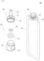
- FIG. 1 is a perspective view of a container according to an embodiment of the present invention
- FIG. 2 is an exploded view of the container according to the embodiment of the present invention
- FIG. 3 is a cross-sectional view of the container according to the embodiment of the present invention.
- a container 1000 may include a container portion 100, a head portion 200, a nozzle 300, and a spout 400.
- the container portion 100 may be made of packaging sheets, and peripheries of at least some packaging sheets may be bonded to each other to form a storage space in which contents are stored.
- a front packaging sheet and a rear packaging sheet may be bonded to each other along peripheries thereof to form the container portion 100, and a storage space configured to accommodate contents may be formed inside the container portion 100.
- the container portion 100 may be referred to as a pouch, but the present invention is not limited thereto.
- the contents stored in the container portion 100 may be a cosmetic material in a liquid, gel, or powder form.
- the contents may include a lotion, a milk lotion, a moisturizing lotion, a nourishing lotion, a skin lotion, a skin softener, a skin toner, an astringent, a massage cream, a nourishing cream, a moisturizing cream, a skin lightening essence, a tone up cream, a liquid sunscreen, sunblock, sun milk, a blemish balm (BB) cream, a base, a foundation, a color correcting (CC) cream, concealer, blusher, contour powder, an eye cream, a primer, and the like.
- the contents are not limited thereto, and other forms or types of cosmetic materials, medical materials, or the like may be applied as the contents.
- the front packaging sheet and the rear packaging sheet are separate sheets and may be combined with each other through bonding.
- the front packaging sheet and the rear packaging sheet may constitute an integrated packaging sheet and may be combined through bonding in a state in which at least some areas are in contact with each other by folding and/or rolling.
- a tear-off portion may be formed in the container portion 100.
- the tear-off portion is for facilitating the tearing of the container portion 100 and may be formed as one area of the container portion 100 is drawn inward.
- the head portion 200 may be disposed at an upper side of the container portion 100 and may discharge the contents, which enter the head portion 200 from the container portion 100, to the nozzle 300.
- the head portion 200 may be formed to have upper and lower portions that communicate with each other, and an accommodation space may be formed in the head portion 200 to allow the contents to be temporarily accommodated therein and then discharged to the nozzle 300.
- a pressing portion 210 may be formed on one surface of the head portion 200.
- the pressing portion 210 may be made of an elastic material and may be elastically deformed inward when an external force is applied thereto. Due to the deformation, the pressure inside the head portion 200 increases. Thus, the contents in the head portion 200 may be moved to the nozzle 300 and/or such movement may be promoted.
- the pressing portion 210 may be formed on a side surface of the head portion 200.
- the present invention is not limited thereto, and according to an embodiment, the head portion 200 may not include the pressing portion 210.
- the communication hole of the guide portion 230 may be formed to have a narrow inner diameter.
- the communication hole may be formed to be narrower than an inner diameter of the head portion 200. Since the contents in the head portion 200 are discharged through the communication hole having a narrow inner diameter, a case in which a large amount of contents enter the nozzle 300 at one time may be prevented.
- the guide portion 230 may include a seating portion which has a catching protrusion formed along a periphery so as to be seated on the upper end of the body portion 220, an extending portion inserted into the body portion 220, and a base portion which is configured to connect a lower end of the extending portion and has the communication hole formed in one area thereof.
- the extending portion may come in close contact with an inner side surface of the body portion 220 to stably fix the guide portion 230 and may prevent leakage of the contents along a boundary between the body portion 220 and the guide portion 230.
- the present invention is not limited thereto.
- the head portion 200 may further include a valve 240 configured to open or close the communication hole of the guide portion 230.
- the valve 240 may seal the communication hole, and in a case in which the pressure inside the head portion 200 changes due to the pressing portion 210, the valve 240 may open the communication hole to allow the contents to head toward the nozzle 300.
- the valve 240 may be a check valve 240 that is disposed in the guide portion 230.
- the present invention is not limited thereto.
- the valve 240 may include a support portion disposed inside the guide portion 230 in close contact therewith, an opening/closing protrusion configured to move up and down according to a pressure change in the head portion 200 to open or close the communication hole of the guide portion 230, and at least one bridge configured to connect the support portion and the opening/closing protrusion to each other.
- the nozzle 300 may include the nozzle tube 310 in which the contents move after entering from the head portion 200 through an inlet 312 and in which a nozzle throat 314, where an inner diameter decreases and then increases, is formed in one area and the nozzle head 320 which is continuous with the nozzle tube 310 and has the outlet 322 formed at an upper end portion.
- the nozzle throat 314 may include a convergent section in which an inner diameter gradually decreases upward and a divergent section which is continuous with the convergent section and in which an inner diameter gradually increases upward.
- a flow velocity of the contents passing through the nozzle tube 310 may firstly decrease due to the bottleneck phenomenon as the contents pass through the convergent section of the nozzle throat 314. Also, the flow velocity of the contents may secondarily decrease as the contents enter the divergent section. In this way, since the flow velocity of the contents moving along the nozzle tube 310 decreases in stages due to the nozzle throat 314, the contents may be prevented from being sprayed at high speed (even when pressure is applied).
- the nozzle head 320 may be formed at an upper end of the nozzle tube 310 so as to surround the contents moving from the nozzle tube 310 and may have the outlet 322 formed at the upper end portion.
- a flow velocity of the contents is very low, an influence of surface tension may significantly increase.
- the nozzle head 320 is formed to surround the contents, the contents may be filled in the nozzle head 320 instead of being immediately discharged through the outlet 322. Then, the contents may be discharged in the form of drops through the outlet 322.
- an inner diameter of the outlet 322 may be formed to be narrower than an inner diameter of the nozzle throat 314 to facilitate formation of drops of the contents.
- the contents may collide with the nozzle head 320 and stop moving. Due to surface tension, the contents in the nozzle head 320 are difficult to be smoothly discharged. Accordingly, the contents that have passed through the nozzle throat 314 may be gradually filled in the nozzle head 320. As a force applied to the filled contents, e.g., the gravity or the like, exceeds the surface tension on the contents at the outlet 322, the contents may be gradually discharged from the outlet 322.
- the contents may agglomerate into spherical shapes and may be formed in the form of drops on an outer side of the outlet 322.
- the size of the drops may gradually increase, and in a case in which the size of the drops increases to a predetermined size or more, the drops may be separated from the outlet 322 and fall.
- the contents since the size of the drops, which are separated from the outlet 322 and fall, are always the same, the contents may be discharged in fixed amounts, and a user may control the number of falling drops to precisely control the use amount of the contents.
- the pressure inside the head portion 200 increases, and a speed at which the nozzle 300 is filled with the contents is increased.
- discharge of the contents from the outlet 322 may be promoted.
- the nozzle 300 may further include a nozzle coupling portion 330 which is formed at a lower side of the nozzle tube 310 and configured to be coupled to the head portion 200.
- the nozzle coupling portion 330 may include an upper wall configured to cover an upper end of the head portion 200 and a sidewall which extends downward along the periphery of the upper wall and is configured to be coupled to a side surface of the head portion 200. Due to the nozzle coupling portion 330, the nozzle 300 may be easily coupled to the head portion 200, and particularly, when coupling the nozzle coupling portion 330 and the head portion 200 to each other, the guide portion 230 seated in the body portion 220 may be fitted and fixed by the body portion 220 and the nozzle coupling portion 330.
- the present invention is not limited thereto.
- the nozzle tube 310, the nozzle head 320, and the nozzle coupling portion 330 may be integrally formed. Also, at least some of the nozzle tube 310, the nozzle head 320, and the nozzle coupling portion 330 may be made of a transparent material or a semitransparent material. However, the present invention is not limited thereto.
- the spout 400 may be coupled to the container portion 100 and communicate with the accommodation space of the container portion 100. Also, the spout 400 may be coupled to the head portion 200 to allow the contents entering the spout 400 from the container portion 100 to move to the head portion 200. According to an embodiment, the spout 400 may be integrally formed with the head portion 200 and/or the nozzle 300 or may be separately formed and then assembled thereto.
- the spout 400 may include a discharge portion 410, a pedestal portion 420, and a bonding portion 430.
- the discharge portion 410 may have a contents movement path formed therein to be passed through and may have a coupling portion formed at an outer side thereof for coupling to the head portion 200.
- a lower side of the contents movement path of the discharge portion 410 may communicate with the storage space of the container portion 100 to allow the contents to enter the discharge portion 410, and the contents may move along the contents movement path and be discharged to an upper side of the contents movement path.
- the pedestal portion 420 may extend outward from a lower side of the coupling portion and may be formed as a flat plate having a circular, elliptical, or polygonal shape.
- the pedestal portion 420 may support a lower end of the head portion 200 to allow the head portion 200 to be more stably coupled to the spout 400.
- the pedestal portion 420 may allow an upper portion of the container portion 100 to be supported by a bottom surface of the pedestal portion 420 to, for example, prevent a case in which the spout 400 moves into the container portion 100 or, conversely, the container portion 100 moves to an upper side (for example, the discharge portion 410 or the like) of the spout 400.
- the pedestal portion 420 may allow an upper end of the container portion 100 to come in contact with the bottom surface of the pedestal portion 420 to guide a position of the container portion 100.
- the pedestal portion 420 may support a lower end of the stopper.
- the bonding portion 430 may be formed to have a predetermined volume at a lower side of the pedestal portion 420 and may be coupled to the container portion 100.
- the volume of the bonding portion 430 may be formed toward a packaging sheet facing the bonding portion 430. Due to the volume, the packaging sheets may, instead of coming in close contact with each other, be spaced apart from each other and form the storage space.
- Various bonding techniques may be applied for coupling the bonding portion 430 to the packaging sheets. For example, various bonding techniques such as chemical bonding using an adhesive, internal-heat bonding (ultrasonic bonding, high-frequency bonding, or the like), and external-heat bonding may be applied.
- the container 1000 illustrated in FIGS. 1 to 3 is only illustrative, and various other configurations may be applied according to an embodiment of the present invention.
- FIG. 4 is a perspective view of a container according to an embodiment of the present invention.
- a container 1000' of FIG. 4 will be described below, and description of details which are the same as those relating to the container 1000 of FIGS. 1 to 3 will be omitted.
- a container portion 100' of the container 1000' may be a pouch which is formed due to bonding of a front packaging sheet and a rear packaging sheet to each other.
- the front packaging sheet and the rear packaging sheet may be integrally formed and may form a storage space by being combined through bonding in a state in which at least some areas are in contact with each other by folding and/or rolling.
- a sealing portion may be formed at only one side of the container portion 100' in a lateral direction. Since a bonding area is reduced, a bonding process may be simplified. In particular, unnecessary processes such as aligning the separately-formed front packaging sheet and rear packaging sheet with each other and widening a gap therebetween may be eliminated.
- the container 1000' illustrated in FIG. 4 is only illustrative, and various other configurations may be applied according to an embodiment of the present invention.
- FIGS. 5 and 6 are perspective views of containers according to different embodiments of the present invention.
- a container 1000" of FIG. 5 and a container 1000'" of FIG. 6 will be described below, and description of details which are the same as those relating to the container 1000 of FIGS. 1 to 3 and the container 1000' of FIG. 4 will be omitted.
- a tear-off portion may be formed in container portions 100" and 100'".
- the tear-off portion is for facilitating the tearing of the container portions 100" and 100′′′ and may be formed as one area of the container portion 100" and one area of the container portion 100′′′ are drawn inward.
- a user may directly use contents in the container portions 100" and 100′′′ by tearing the container portions 100" and 100′′′ through the tear-off portion. For example, even in a case in which a considerable amount of contents has been used and it is difficult to discharge any more contents through the spout 400, a user may tear the container portions 100" and 100′′′ to take out and use the contents remaining in the container portions 100" and 100'". Also, through the tear-off portion, the container portions 100" and 100′′′ may be separated from the spout 400 or, from the spout 400 and portions of the container portions 100" and 100′′′ attached to the spout 400, the residual container portions 100" and 100′′′ may be separated in order to enable recycling of the separated container portions 100" and 100'". To this end, the tear-off portion may be disposed at portions of the container portions 100" and 100′′′ that are adjacent to a lower side of the spout 400. However, the present invention is not limited thereto.
- the tear-off portion may be formed on a sealing portion that is formed along the periphery of the container portions 100" and 100'". Since the tear-off portion is formed in one area of the sealing portion, a case in which the shape of the container portions 100" and 100′′′ collapses due to the tear-off portion or sealing performance of the container portions 100" and 100′′′ degrades due to the tear-off portion may be prevented.
- the tear-off portion may be formed to become narrower toward the inside.
- the innermost side of the tear-off portion may be formed to be angular. This is to facilitate tearing using the tear-off portion.
- FIGS. 7 and 8 are views for describing a container set according to an embodiment of the present invention.
- a container set 4000 may include a refill container 2000 and an applicator 3000.
- the refill container 2000 may include the container portion 100, the spout 400, and the stopper 500.
- the refill container 2000 may be provided as one or more refill containers 2000, and the container portions 100 of the refill containers 2000 may store the same or different contents.
- the stopper 500 may be detachably coupled to the spout 400 to seal the spout 400.
- the applicator 3000 may include the head portion 200 and the nozzle 300.
- the container portion 100 is illustrated in FIG. 7 , this is only illustrative, and the container portion 100', the container portion 100", the container portion 100'", or other container portions may be included in the refill container 2000.
- the stopper 500 of the refill container may be removed to expose the spout 400 of the refill container, and then the head portion 200 of the applicator 3000 may be coupled to the spout 400 to form the container 1000 from the container set 4000.
- a coupling method e.g., screw coupling or the like
- a coupling method e.g., screw coupling or the like
- a coupling method e.g., screw coupling or the like
- FIGS. 7 and 8 The container set illustrated in FIGS. 7 and 8 is only illustrative, and various other configurations may be applied according to an embodiment of the present invention.
- FIG. 9 shows a perspective view and a front view of an applicator according to an embodiment of the present invention.
- an applicator 3000' may include a spout 400' and a nozzle 300'.
- the spout 400' and the nozzle 300' of the applicator 3000' will be described below, and description of details which are the same as those relating to the spout 400 and the nozzle 300 of FIGS. 1 to 8 will be omitted.
- the spout 400' and the nozzle 300' may be integrally formed. That is, the nozzle 300' may directly extend from the spout 400', and thus an element, such as a nozzle coupling portion, for coupling the nozzle 300' to another element (e.g., a head portion) may be excluded. Likewise, an element such as the head portion may also be excluded, and thus, contents may directly enter the nozzle 300' from a discharge portion of the spout 400' instead of entering from the head portion.
- an element such as the head portion may also be excluded, and thus, contents may directly enter the nozzle 300' from a discharge portion of the spout 400' instead of entering from the head portion.
- the applicator 3000' may be made of a recyclable material.
- the applicator 3000' may be separated from the container portion and recycled.
- the applicator 3000' may be made of a single material such as polypropylene (PP) or polyester (PE) or may be made of a biodegradable material or the like.
- PP polypropylene
- PE polyester
- the present invention is not limited thereto.
- the applicator 3000' illustrated in FIG. 9 is only illustrative, and various other configurations may be applied according to an embodiment of the present invention.
- FIG. 10 is a cross-sectional view of a packaging sheet according to an embodiment of the present invention.
- the packaging sheet may be used in the container portions 100, 100', 100", and 100′′′ of FIGS. 1 to 8 , but the present invention is not limited thereto.
- a packaging sheet 600 may include a paper layer 610, a first film layer 620, a second film layer 630, and a print layer 640.
- the paper layer 610 is a base made of paper.
- the paper layer 610 may be made of chemical wood pulp such as bleached kraft pulp of broad-leaved trees, bleached kraft pulp of needle-leaved trees, and sulfite pulp, mechanical wood pulp such as stone-ground pulp, thermomechanical pulp, and chemithermomechanical pulp, deinked pulp (DIP), or non-timber fibers obtained from kenaf, bamboo, hemp, or the like.
- the paper layer 610 may be made of traditional Korean paper (hanji), parchment, yellow parchment, kraft paper, white paperboard, tissue paper, art paper, Manila paper, ivory paper, medium quality paper, groundwood paper, glassine paper, or tracing paper.
- the paper layer 610 may be compressed.
- the compression may be performed by applying heat and pressure to the paper layer 610 while passing the paper layer 610 between two rollers. In this way, while surface treatment is performed on the paper layer 610, the paper layer 610 may be compressed. Due to the compression, a density of the paper layer 610 may be increased, and a surface of the paper layer 610 may be evenly formed. In this way, a film layer, the print layer 640, or the like may be uniformly coupled to the paper layer 610, and blocking performance of the paper layer 610 itself may be improved.
- the paper layer 610 may be surface-treated.
- the surface treatment may be performed by coating the surface of the paper layer 610 with a surface treatment material.
- the surface treatment material may include starch, a starch derivative, polyvinyl alcohol (PVA), carboxymethyl cellulose (CMC), latex, and the like.
- the first film layer 620 may be disposed below the paper layer 610 and may prevent contents inside the container from being absorbed into the paper layer 610 and may block the contents from gas, oxygen, moisture, ultraviolet light, or the like.
- the first film layer 620 may be made of one or more selected from the group consisting of linear low density polyethylene (LLDPE), low density polyethylene (LDPE), casting polypropylene, polylactic acid, and polybutylene succinate and may effectively prevent the contents from being absorbed into the paper layer 610.
- LLDPE linear low density polyethylene
- LDPE low density polyethylene
- casting polypropylene polylactic acid
- polybutylene succinate may effectively prevent the contents from being absorbed into the paper layer 610.
- the second film layer 630 may be disposed between the first film layer 620 and the paper layer 610 to improve the overall strength of the packaging sheet 600. Due to the second film layer 630, a problem in which the packaging sheet 600 is damaged due to lack of strength may be effectively addressed.
- the second film layer 630 may be made of one or more selected from the group consisting of polyethylene terephthalate (PET), glycol-modified polyethylene terephthalate (PETG), post-consumer recycled polyethylene terephthalate (PCR-PET), polyethylene, polypropylene (PP), polyester (PE), polymethyl methacrylate (PMMA), and a styrene-acrylonitrile copolymer (SAN).
- the second film layer 630 may be formed by being deposited on an upper surface of the first film layer 620. Accordingly, the second film layer 630 may be formed in a small uniform thickness on the upper surface of the first film layer 620 and then used together with the first film layer 620.
- a deposition layer of the present invention may be formed by a known deposition technique such as chemical vapor deposition (CVD) or physical vapor deposition (PVD), or various other known deposition techniques may be applied according to an embodiment.
- CVD chemical vapor deposition
- PVD physical vapor deposition
- the first film layer 620 and the second film layer 630 may be biodegradable.
- the first film layer 620 and the second film layer 630 may include at least one of a biodegradable resin and an oxo-biodegradable resin.
- the biodegradable resin may include both a natural product-based biodegradable resin, which is manufactured by preprocessing biomass, obtaining a sugar through a saccharification process, and polymerizing high molecular monomers produced through a fermentation process, and a petroleum-based biodegradable resin which is manufactured using a petrochemical-derived substance.
- the biodegradable resin may be selected from the group consisting of polylactic acid (PLA) and a copolymer thereof, polycaprolactone (PCL), polyglycolic acid (PGA), polyether sulfone (PES), polybutylene succinate (PBS), polybutylene succinate adipate (PBSA), cellulose-based compounds, polyhydroxy alkylate (PHA), polybutylene adipate terephthalate (PBAT), polybutylene succinate terephthalate (PBST) resin, and mixtures thereof but is not limited thereto.
- PLA polylactic acid
- PCL polycaprolactone
- PGA polyglycolic acid
- PES polyether sulfone
- PBS polybutylene succinate
- PBSA polybutylene succinate adipate
- PHA polyhydroxy alkylate
- PAT polybutylene adipate terephthalate
- PBST polybutylene succinate terephthalate
- the oxo-biodegradable resin is manufactured by adding biomass, an oxo-biodegradation agent, a compatibilizer, a biodegradation accelerator, an automatic oxidizing agent, or the like to conventional general-purpose plastics.
- the oxo-biodegradable resin may include various types of oxo-biodegradable resins such as an oxo bio-polypropylene (PP)-based oxo-biodegradable resin and an oxo bio-polyethylene (PE)-based oxo-biodegradable resin, but are not limited thereto.
- an adhesive layer (not illustrated) may be disposed between the paper layer 610 and the second film layer 630.
- the adhesive layer is for adhering the second film layer 630 to the paper layer 610.
- the adhesive layer may be formed by applying an adhesive on the paper layer 610 and/or the second film layer 630 and then compressing the paper layer 610 and the second film layer 630. Since the paper layer 610 is compressed to high density by the compression and has high moisture blocking performance, the adhesive may form a single layer between the paper layer 610 and the second film layer 630, and the adhesive may show uniform and improved adhesive performance throughout the entire adhesive area.
- the adhesive layer may be formed of a water-degradable adhesive. Accordingly, water degradation of the adhesive layer may allow the second film layer 630 and the paper layer 610 to be easily separated from each other.
- the adhesive may be an emulsion-type water-based adhesive in which an adhesive is dispersed in water.
- the adhesive may be a water-based urethane adhesive.
- the present invention is not limited thereto, and various other natural water-based adhesives (e.g., starch, protein, animal glue, casein, natural rubber, latex, and the like) and synthetic water-based adhesives (e.g., a water-based acrylic adhesive or the like) may be used as the adhesive.
- the adhesive layer may be made of a biodegradable material like the paper layer 610 and the second film layer 630.
- the adhesive layer may be made of a biodegradable resin or an oxo-biodegradable resin.
- the second film layer 630 may be directly bonded to the paper layer 610.
- various bonding techniques such as internal-heat bonding (ultrasonic bonding, high-frequency bonding, or the like) and external-heat bonding may be applied.
- a heating plate may be compressed to an outer portion of the second film layer 630 to conduct heat thereto, and in this way, the melted second film layer 630 may be adhered to the paper layer 610.
- the print layer 640 is formed by printing on an upper side of the paper layer 610 and may include a first print layer 641 and a second print layer 642.
- the first print layer 641 may be formed by applying water-based ink on an upper surface of the paper layer 610.
- the first print layer 641 may form a predetermined shape, letter, drawing, or color on the surface of the paper layer 610.
- the water-based ink may be eco-friendly ink that contains water at 90 wt% or more. Examples of the water-based ink may include polyurethane ink, acrylic ink, or the like.
- the water-based ink and water-based coating solution may not be absorbed into the paper layer 610 or only a very small amount of the water-based ink and water-based coating solution may be absorbed into the paper layer 610, and the remaining water-based ink and remaining water-based coating solution may form the first print layer 641 and the second print layer 642, respectively.
- both the water-based ink forming the first print layer 641 and the water-based coating solution forming the second print layer 642 may be water-degradable. Accordingly, the print layer 640 may be separated from the paper layer 610 through water degradation.
- a thin film layer (not illustrated) may be formed on an upper side of the paper layer 610.
- the thin film layer may be formed by hot-stamping a hot-stamping foil on upper surfaces of the paper layer 610, the first print layer 641, and/or the second print layer 642.
- the thin film layer may give a metallic texture to the packaging sheet 600 and thus maximize the aesthetic appearance thereof.
- the packaging sheet 600 may further include a water-based blocking layer (not illustrated).
- the water-based blocking layer may be formed by applying a water-based blocking solution on at least one surface of the paper layer 610. Since the paper layer 610 is compressed to high density by the compression and has high moisture blocking performance, even when the water-based blocking solution is applied on the paper layer 610, the water-based blocking solution may not be absorbed into the paper layer 610 or only a very small amount of the water-based blocking solution may be absorbed into the paper layer 610, and the remaining water-based blocking solution may form a single layer on the surface of the paper layer 610.
- the water-based blocking layer may be disposed between the paper layer 610 and the print layer 640 and/or disposed between the paper layer 610 and the adhesive layer. That is, by allowing the blocking layer to form a single layer along the paper layer 610 instead of being absorbed into the paper layer 610, the blocking layer may provide more uniform and improved moisture and gas blocking performance.
- the water-based blocking solution may include a high molecular polymer that does not include a hydrophilic group.
- the water-based blocking solution may include a vinyl chloride polymer, an ethylene vinyl alcohol polymer, a styrene-butadiene-based polymer, a styrene-acrylic-based polymer, a polyvinyl alcohol polymer, a vinylidene chloride polymer, and the like, but is not limited thereto.
Landscapes
- Engineering & Computer Science (AREA)
- Mechanical Engineering (AREA)
- Life Sciences & Earth Sciences (AREA)
- Biodiversity & Conservation Biology (AREA)
- Packages (AREA)
- Containers And Packaging Bodies Having A Special Means To Remove Contents (AREA)
Abstract
Description
- The present invention relates to a container, and more particularly, to a container using an eco-friendly material and capable of discharging contents in fixed amounts.
- With the economic development and the growing design awareness of consumers, cosmetic products have emerged as an essential consumption item that not only provides skin protection and lightening functions to consumers but also satisfies the aesthetic needs of consumers.
- Generally, cosmetic products are sold in glass bottles or containers molded from plastic. Such glass bottles or containers made of plastic have a problem in that it is difficult to use the cosmetic product remaining at the bottom of the container. Further, such cosmetic containers have a problem of being difficult to reuse, thus causing environmental pollution.
- Also, in order to prevent wasting of cosmetic products and prevent excessive skin irritation, there is a need to use a cosmetic product in a fixed amount every time. However, in the case of conventional cosmetic containers, it is difficult to control the amount of liquid contents being discharged every time, and thus there is a problem of having difficulty in using a cosmetic product in a fixed amount every time.
- The present invention is directed to providing a container using an eco-friendly material and capable of discharging contents in fixed amounts.
- The technical objectives of the present invention are not limited to the above objective, and other objectives may become apparent to those of ordinary skill in the art from the following description.
- An embodiment of the present invention provides a container. The container includes a container portion configured to form a storage space in which contents are stored, a head portion disposed at an upper side of the container portion and configured to promote discharge of the contents, which enter the head portion from the container portion, through an internal pressure change caused by a pressing portion which is formed at one side of the head portion and made of an elastic material, and a nozzle configured to discharge the contents, which enter the nozzle from the head portion, in fixed amounts.
- The nozzle may be formed to extend upward from the head portion and may decrease a flow velocity of the contents, which enter from the head portion, in stages to discharge the contents in fixed amounts.
- The nozzle may include a nozzle tube in which the contents move after entering from the head portion through an inlet and in which a nozzle throat, where an inner diameter decreases and then increases, is formed in one area and a nozzle head which is disposed at an upper end of the nozzle tube and in which an outlet is formed at an upper side, wherein a movement speed of the contents may decrease as the contents pass through the nozzle throat, and the contents may be filled inside the nozzle head and then discharged.
- The head portion may include a body portion which has the pressing portion formed at a side surface and has an upper side coupled to the nozzle, a guide portion which is disposed at an upper end of the body portion and allows the contents in the head portion to head toward the nozzle through a communication hole, and a valve disposed in the guide portion to open or close the communication hole.
- The guide portion may include a seating portion which has a catching protrusion formed along a periphery so as to be seated on the upper end of the body portion, an extending portion inserted into the body portion, and a base portion which is configured to connect a lower end of the extending portion and has the communication hole formed in one area thereof, wherein the valve may be disposed inside the extending portion and the base portion.
- The container portion may be a pouch which is formed due to bonding of peripheries of one or more packaging sheets, and the packaging sheet may include a paper layer, a first film layer disposed at a lower side of the paper layer to prevent absorption of the contents into the paper layer, and a second film layer disposed between the paper layer and the first film layer to improve the strength of the packaging sheet.
- The second film layer may be formed to be deposited on one surface of the first film layer.
- A material of the second film layer may include at least one of polyethylene terephthalate (PET), glycol-modified polyethylene terephthalate (PETG), post-consumer recycled polyethylene terephthalate (PCR-PET), polyethylene, polypropylene (PP), polyester (PE), polymethyl methacrylate (PMMA), and a styrene-acrylonitrile copolymer (SAN).
- The packaging sheet may further include an adhesive layer configured to adhere the second film layer and the paper layer to each other between the second film layer and the paper layer, and the adhesive layer may be formed of a water-degradable adhesive, and due to the water degradation of the adhesive layer, the paper layer may be separated from the first film layer and the second film layer.
- The container may further include a spout which is coupled to the container portion so as to be able to communicate therewith and has a contents movement path formed therein to allow the contents to enter and be discharged, a tear-off portion may be formed in the container portion as one area thereof is drawn inward, and by tearing off the container portion along the tear-off portion, at least a portion of the container portion may be separated from the spout.
- An embodiment of the present invention provides a container set. The set includes a plurality of refill containers and an applicator. The refill container may include a container portion configured to form a storage space in which contents are stored, a spout which is coupled to the container portion so as to be able to communicate therewith and has a contents movement path formed therein to allow the contents to enter and be discharged, and a stopper detachably coupled to the spout to seal the spout. The applicator may include a head portion having a pressing portion made of an elastic material formed at one side and a nozzle coupled to the head portion to discharge the contents in fixed amounts. The head portion of the applicator may be detachably coupled to the spout to allow the plurality of refill containers to be replaceably used with respect to the applicator.
- An embodiment of the present invention provides a packaging sheet. The packaging sheet may include a paper layer, a first film layer disposed at a lower side of the paper layer to prevent absorption of the contents into the paper layer, and a second film layer disposed between the paper layer and the first film layer to improve the strength of the packaging sheet.
- The packaging sheet may be provided as one or more packaging sheets, and peripheries of the one or more packaging sheets may be bonded to form a pouch.
- The second film layer may be formed to be deposited on one surface of the first film layer.
- The packaging sheet may further include an adhesive layer configured to adhere the second film layer and the paper layer to each other between the second film layer and the paper layer, and the adhesive layer may be formed of a water-degradable adhesive, and due to the water degradation of the adhesive layer, the paper layer may be separated from the first film layer and the second film layer.
- An embodiment of the present invention provides a nozzle. The nozzle may decrease a flow velocity of the contents, which move inside the nozzle, in stages to discharge the contents in fixed amounts.
- The nozzle may include a nozzle tube in which the contents move after entering through an inlet and in which a nozzle throat, where an inner diameter decreases and then increases, is formed in one area and a nozzle head which is disposed at an upper end of the nozzle tube and in which an outlet is formed at an upper side.
- A movement speed of the contents may decrease as the contents pass through the nozzle throat, and the contents may be filled inside the nozzle head and then discharged.
- An embodiment of the present invention provides a container. The container includes a container portion configured to form a storage space in which contents are stored, a spout coupled to the container portion and through which the contents in the container portion are discharged, and a nozzle configured to discharge the contents, which enter from the spout, in fixed amounts, wherein the spout and the nozzle may be integrally formed.
- The nozzle may decrease a flow velocity of the contents, which enter from the spout, in stages to discharge the contents in fixed amounts.
- The nozzle may include a nozzle tube in which the contents move after entering from the spout through an inlet and in which a nozzle throat, where an inner diameter decreases and then increases, is formed in one area and a nozzle head which is disposed at an upper end of the nozzle tube and in which an outlet is formed at an upper side, wherein a movement speed of the contents may decrease as the contents pass through the nozzle throat, and the contents may be filled inside the nozzle head and then discharged.
- The container portion may be a pouch which is formed due to bonding of peripheries of one or more packaging sheets, and the packaging sheet may include a paper layer, a first film layer disposed at a lower side of the paper layer to prevent absorption of the contents into the paper layer, and a second film layer disposed between the paper layer and the first film layer to improve the strength of the packaging sheet.
- The second film layer may be formed to be deposited on one surface of the first film layer.
- The packaging sheet may further include an adhesive layer configured to adhere the second film layer and the paper layer to each other between the second film layer and the paper layer, and the adhesive layer may be formed of a water-degradable adhesive, and due to the water degradation of the adhesive layer, the paper layer may be separated from the first film layer and the second film layer.
- A tear-off portion may be formed in the container portion as one area thereof is drawn inward, and by tearing off the container portion along the tear-off portion, at least a portion of the container portion may be separated from the spout.
- According to the present invention, a packaging sheet has a paper layer as a base and can provide excellent blocking performance without using a layer made of a metal such as aluminium.
- Also, according to the present invention, in the packaging sheet, the paper layer and a film layer can be easily separated from each other through water degradation.
- Also, according to the present invention, a container is made of an eco-friendly material to reduce environmental pollution and is manufactured in the form of a pouch to facilitate withdrawal of contents.
- Also, according to the present invention, contents can be discharged in fixed amounts in the form of drops through a nozzle, and a discharge speed can be controlled by pressure.
- Also, according to the present invention, a flow velocity of contents being discharged is gradually decreased to prevent a case in which a large amount of fluid is discharged at one time or the contents are not discharged in the form of drops.
- A brief description of each drawing will be provided for better understanding of the drawings referenced in the detailed description of the present invention.
-
FIG. 1 is a perspective view of a container according to an embodiment of the present invention. -
FIG. 2 is an exploded view of the container according to the embodiment of the present invention. -
FIG. 3 is a cross-sectional view of the container according to the embodiment of the present invention. -
FIG. 4 is a perspective view of a container according to an embodiment of the present invention. -
FIG. 5 is a perspective view of a container according to an embodiment of the present invention. -
FIG. 6 is a perspective view of a container according to an embodiment of the present invention. -
FIG. 7 is a view for describing a container set according to an embodiment of the present invention. -
FIG. 8 is a view for describing the container set according to the embodiment of the present invention. -
FIG. 9 shows a perspective view and a front view of an applicator according to an embodiment of the present invention. -
FIG. 10 is a cross-sectional view of a packaging sheet according to an embodiment of the present invention. - Hereinafter, exemplary embodiments according to the present invention will be described in detail with reference to the accompanying drawings. The same reference numeral or symbol throughout the drawings indicates a component or element that performs substantially the same function. For convenience of description, directions such as vertical and horizontal mentioned herein are based on the drawings, and the scope of the present invention is not necessarily limited by the corresponding directions.
- Terms including ordinals such as first and second may be used to describe various elements, but the elements are not limited by the terms. The terms are only used for the purpose of distinguishing one element from another element. For example, without departing from the scope of the present invention, a first element may be referred to as a second element, and likewise, a second element may also be referred to as a first element. The term and/or includes a combination of a plurality of related items or any one item among the plurality of related items.
- Terms used herein are used to describe embodiments and are not intended to limit and/or restrict the present invention. A singular expression includes a plural expression unless the context clearly indicates otherwise. In the specification, terms such as "include" or "have" should be understood as specifying that features, number, steps, operations, elements, components, or combinations thereof are present and not as precluding the possibility of the presence or addition of one or more other features, numbers, steps, operations, elements, components, or combinations thereof in advance.
- Throughout the specification, when a certain part is described as being connected to another part, this not only includes a case in which the certain part is directly connected to the other part but also includes a case in which the certain part is electrically connected to the other part while another device is disposed therebetween. Also, when a certain part is described as including a certain element, this signifies that the certain part may further include another element rather than excluding the other element unless particularly described otherwise.
-
FIG. 1 is a perspective view of a container according to an embodiment of the present invention,FIG. 2 is an exploded view of the container according to the embodiment of the present invention, andFIG. 3 is a cross-sectional view of the container according to the embodiment of the present invention. - Referring to
FIGS. 1 to 3 , acontainer 1000 may include acontainer portion 100, ahead portion 200, anozzle 300, and aspout 400. - The
container portion 100 may be made of packaging sheets, and peripheries of at least some packaging sheets may be bonded to each other to form a storage space in which contents are stored. For example, a front packaging sheet and a rear packaging sheet may be bonded to each other along peripheries thereof to form thecontainer portion 100, and a storage space configured to accommodate contents may be formed inside thecontainer portion 100. Here, thecontainer portion 100 may be referred to as a pouch, but the present invention is not limited thereto. - In an embodiment, the contents stored in the
container portion 100 may be a cosmetic material in a liquid, gel, or powder form. Examples of the contents may include a lotion, a milk lotion, a moisturizing lotion, a nourishing lotion, a skin lotion, a skin softener, a skin toner, an astringent, a massage cream, a nourishing cream, a moisturizing cream, a skin lightening essence, a tone up cream, a liquid sunscreen, sunblock, sun milk, a blemish balm (BB) cream, a base, a foundation, a color correcting (CC) cream, concealer, blusher, contour powder, an eye cream, a primer, and the like. However, the contents are not limited thereto, and other forms or types of cosmetic materials, medical materials, or the like may be applied as the contents. - In an embodiment, an area where the front packaging sheet and the rear packaging sheet are bonded to each other may form a sealing portion. The sealing portion may have improved strength, durability, and sealability as compared to other areas of the packaging sheets. Therefore, due to the sealing portion, leakage of the contents to the outside may be prevented, and the shape of the
container portion 100 may be maintained. Here, in bonding to form the sealing portion, various bonding techniques such as chemical bonding using an adhesive, internal-heat bonding (ultrasonic bonding, high-frequency bonding, or the like), and external-heat bonding may be applied. - In an embodiment, the front packaging sheet and the rear packaging sheet are separate sheets and may be combined with each other through bonding. However, this is only illustrative, and various other configurations may be applied according to an embodiment. For example, the front packaging sheet and the rear packaging sheet may constitute an integrated packaging sheet and may be combined through bonding in a state in which at least some areas are in contact with each other by folding and/or rolling.
- According to an embodiment, a tear-off portion may be formed in the
container portion 100. The tear-off portion is for facilitating the tearing of thecontainer portion 100 and may be formed as one area of thecontainer portion 100 is drawn inward. - The
head portion 200 may be disposed at an upper side of thecontainer portion 100 and may discharge the contents, which enter thehead portion 200 from thecontainer portion 100, to thenozzle 300. - In an embodiment, the
head portion 200 may be formed to have upper and lower portions that communicate with each other, and an accommodation space may be formed in thehead portion 200 to allow the contents to be temporarily accommodated therein and then discharged to thenozzle 300. - In an embodiment, a
pressing portion 210 may be formed on one surface of thehead portion 200. Thepressing portion 210 may be made of an elastic material and may be elastically deformed inward when an external force is applied thereto. Due to the deformation, the pressure inside thehead portion 200 increases. Thus, the contents in thehead portion 200 may be moved to thenozzle 300 and/or such movement may be promoted. In order to facilitate holding and using thehead portion 200, thepressing portion 210 may be formed on a side surface of thehead portion 200. However, the present invention is not limited thereto, and according to an embodiment, thehead portion 200 may not include thepressing portion 210. - In an embodiment, the
head portion 200 may include abody portion 220 and aguide portion 230. Thebody portion 220 may be vertically passed through, may form the accommodation space therein, and may have thepressing portion 210 formed on a side surface thereof. Also, theguide portion 230 may be disposed at an upper end of thebody portion 220 to allow the contents to head toward thenozzle 300 through a communication hole formed in theguide portion 230. According to an embodiment, theguide portion 230 and thebody portion 220 may be integrally formed or may be separately formed and then assembled. - In an embodiment, the communication hole of the
guide portion 230 may be formed to have a narrow inner diameter. For example, the communication hole may be formed to be narrower than an inner diameter of thehead portion 200. Since the contents in thehead portion 200 are discharged through the communication hole having a narrow inner diameter, a case in which a large amount of contents enter thenozzle 300 at one time may be prevented. - In an embodiment, the
guide portion 230 may include a seating portion which has a catching protrusion formed along a periphery so as to be seated on the upper end of thebody portion 220, an extending portion inserted into thebody portion 220, and a base portion which is configured to connect a lower end of the extending portion and has the communication hole formed in one area thereof. Here, the extending portion may come in close contact with an inner side surface of thebody portion 220 to stably fix theguide portion 230 and may prevent leakage of the contents along a boundary between thebody portion 220 and theguide portion 230. However, the present invention is not limited thereto. - In an embodiment, the
head portion 200 may further include avalve 240 configured to open or close the communication hole of theguide portion 230. Specifically, thevalve 240 may seal the communication hole, and in a case in which the pressure inside thehead portion 200 changes due to thepressing portion 210, thevalve 240 may open the communication hole to allow the contents to head toward thenozzle 300. For example, thevalve 240 may be acheck valve 240 that is disposed in theguide portion 230. However, the present invention is not limited thereto. - In an embodiment, the
valve 240 may include a support portion disposed inside theguide portion 230 in close contact therewith, an opening/closing protrusion configured to move up and down according to a pressure change in thehead portion 200 to open or close the communication hole of theguide portion 230, and at least one bridge configured to connect the support portion and the opening/closing protrusion to each other. - The
nozzle 300 may be formed above thehead portion 200 and may discharge the contents that enter thenozzle 300 from thehead portion 200. - In an embodiment, a flow velocity of the contents may be decreased as the contents pass through the
nozzle 300. The contents with decreased velocity may be discharged in the form of drops. According to an embodiment, a change in pressure inside thehead portion 200 due to thepressing portion 210 may promote discharge of the contents. - In an embodiment, an inner diameter of the
nozzle 300 may be formed to be narrow so that, due to surface tension, the contents are not easily discharged to the outside of thenozzle 300. Also, the contents may be filled in an upper end portion (or a nozzle head 320) of thenozzle 300 and then discharged. To this end, an inner diameter of anoutlet 322 of thenozzle 300 may be formed to be narrower than an inner diameter of other areas (for example, anozzle tube 310, the nozzle head 320) of thenozzle 300. However, the present invention is not limited thereto. - In an embodiment, the
nozzle 300 may include thenozzle tube 310 in which the contents move after entering from thehead portion 200 through aninlet 312 and in which anozzle throat 314, where an inner diameter decreases and then increases, is formed in one area and thenozzle head 320 which is continuous with thenozzle tube 310 and has theoutlet 322 formed at an upper end portion. - In an embodiment, the
nozzle throat 314 may include a convergent section in which an inner diameter gradually decreases upward and a divergent section which is continuous with the convergent section and in which an inner diameter gradually increases upward. A flow velocity of the contents passing through thenozzle tube 310 may firstly decrease due to the bottleneck phenomenon as the contents pass through the convergent section of thenozzle throat 314. Also, the flow velocity of the contents may secondarily decrease as the contents enter the divergent section. In this way, since the flow velocity of the contents moving along thenozzle tube 310 decreases in stages due to thenozzle throat 314, the contents may be prevented from being sprayed at high speed (even when pressure is applied). - In an embodiment, the
nozzle head 320 may be formed at an upper end of thenozzle tube 310 so as to surround the contents moving from thenozzle tube 310 and may have theoutlet 322 formed at the upper end portion. The contents that have passed through thenozzle tube 310, particularly, thenozzle throat 314, move to thenozzle head 320. Here, since a flow velocity of the contents is very low, an influence of surface tension may significantly increase. In addition, since thenozzle head 320 is formed to surround the contents, the contents may be filled in thenozzle head 320 instead of being immediately discharged through theoutlet 322. Then, the contents may be discharged in the form of drops through theoutlet 322. Here, for example, an inner diameter of theoutlet 322 may be formed to be narrower than an inner diameter of thenozzle throat 314 to facilitate formation of drops of the contents. - In an embodiment, after the movement speed of the contents discharged to the
nozzle 300 decreases in stages as the contents pass through thenozzle tube 310, the contents may collide with thenozzle head 320 and stop moving. Due to surface tension, the contents in thenozzle head 320 are difficult to be smoothly discharged. Accordingly, the contents that have passed through thenozzle throat 314 may be gradually filled in thenozzle head 320. As a force applied to the filled contents, e.g., the gravity or the like, exceeds the surface tension on the contents at theoutlet 322, the contents may be gradually discharged from theoutlet 322. Here, due to surface tension, the contents may agglomerate into spherical shapes and may be formed in the form of drops on an outer side of theoutlet 322. Then, as the contents are gradually discharged from theoutlet 322, the size of the drops may gradually increase, and in a case in which the size of the drops increases to a predetermined size or more, the drops may be separated from theoutlet 322 and fall. Here, since the size of the drops, which are separated from theoutlet 322 and fall, are always the same, the contents may be discharged in fixed amounts, and a user may control the number of falling drops to precisely control the use amount of the contents. - In an embodiment, when the user presses the
pressing portion 210, the pressure inside thehead portion 200 increases, and a speed at which thenozzle 300 is filled with the contents is increased. Thus, discharge of the contents from theoutlet 322 may be promoted. - In an embodiment, the
nozzle 300 may further include anozzle coupling portion 330 which is formed at a lower side of thenozzle tube 310 and configured to be coupled to thehead portion 200. Thenozzle coupling portion 330 may include an upper wall configured to cover an upper end of thehead portion 200 and a sidewall which extends downward along the periphery of the upper wall and is configured to be coupled to a side surface of thehead portion 200. Due to thenozzle coupling portion 330, thenozzle 300 may be easily coupled to thehead portion 200, and particularly, when coupling thenozzle coupling portion 330 and thehead portion 200 to each other, theguide portion 230 seated in thebody portion 220 may be fitted and fixed by thebody portion 220 and thenozzle coupling portion 330. However, the present invention is not limited thereto. - In an embodiment, the
nozzle tube 310, thenozzle head 320, and thenozzle coupling portion 330 may be integrally formed. Also, at least some of thenozzle tube 310, thenozzle head 320, and thenozzle coupling portion 330 may be made of a transparent material or a semitransparent material. However, the present invention is not limited thereto. - The
spout 400 may be coupled to thecontainer portion 100 and communicate with the accommodation space of thecontainer portion 100. Also, thespout 400 may be coupled to thehead portion 200 to allow the contents entering thespout 400 from thecontainer portion 100 to move to thehead portion 200. According to an embodiment, thespout 400 may be integrally formed with thehead portion 200 and/or thenozzle 300 or may be separately formed and then assembled thereto. - In an embodiment, the
spout 400 may include adischarge portion 410, apedestal portion 420, and abonding portion 430. - In an embodiment, the
discharge portion 410 may have a contents movement path formed therein to be passed through and may have a coupling portion formed at an outer side thereof for coupling to thehead portion 200. A lower side of the contents movement path of thedischarge portion 410 may communicate with the storage space of thecontainer portion 100 to allow the contents to enter thedischarge portion 410, and the contents may move along the contents movement path and be discharged to an upper side of the contents movement path. - In an embodiment, the
pedestal portion 420 may extend outward from a lower side of the coupling portion and may be formed as a flat plate having a circular, elliptical, or polygonal shape. When thehead portion 200 is coupled to thedischarge portion 410, thepedestal portion 420 may support a lower end of thehead portion 200 to allow thehead portion 200 to be more stably coupled to thespout 400. Also, thepedestal portion 420 may allow an upper portion of thecontainer portion 100 to be supported by a bottom surface of thepedestal portion 420 to, for example, prevent a case in which thespout 400 moves into thecontainer portion 100 or, conversely, thecontainer portion 100 moves to an upper side (for example, thedischarge portion 410 or the like) of thespout 400. Also, when coupling thecontainer portion 100 and thespout 400 to each other, thepedestal portion 420 may allow an upper end of thecontainer portion 100 to come in contact with the bottom surface of thepedestal portion 420 to guide a position of thecontainer portion 100. According to an embodiment, in a case in which a stopper (astopper 500 ofFIGS. 7 and8 ) is coupled to thespout 400, thepedestal portion 420 may support a lower end of the stopper. - In an embodiment, the
bonding portion 430 may be formed to have a predetermined volume at a lower side of thepedestal portion 420 and may be coupled to thecontainer portion 100. The volume of thebonding portion 430 may be formed toward a packaging sheet facing thebonding portion 430. Due to the volume, the packaging sheets may, instead of coming in close contact with each other, be spaced apart from each other and form the storage space. Various bonding techniques may be applied for coupling thebonding portion 430 to the packaging sheets. For example, various bonding techniques such as chemical bonding using an adhesive, internal-heat bonding (ultrasonic bonding, high-frequency bonding, or the like), and external-heat bonding may be applied. - The
container 1000 illustrated inFIGS. 1 to 3 is only illustrative, and various other configurations may be applied according to an embodiment of the present invention. -
FIG. 4 is a perspective view of a container according to an embodiment of the present invention. - A container 1000' of
FIG. 4 will be described below, and description of details which are the same as those relating to thecontainer 1000 ofFIGS. 1 to 3 will be omitted. - Referring to
FIG. 4 , a container portion 100' of the container 1000' may be a pouch which is formed due to bonding of a front packaging sheet and a rear packaging sheet to each other. Here, the front packaging sheet and the rear packaging sheet may be integrally formed and may form a storage space by being combined through bonding in a state in which at least some areas are in contact with each other by folding and/or rolling. - In this case, a sealing portion may be formed at only one side of the container portion 100' in a lateral direction. Since a bonding area is reduced, a bonding process may be simplified. In particular, unnecessary processes such as aligning the separately-formed front packaging sheet and rear packaging sheet with each other and widening a gap therebetween may be eliminated.
- The container 1000' illustrated in
FIG. 4 is only illustrative, and various other configurations may be applied according to an embodiment of the present invention. -
FIGS. 5 and6 are perspective views of containers according to different embodiments of the present invention. - A
container 1000" ofFIG. 5 and a container 1000'" ofFIG. 6 will be described below, and description of details which are the same as those relating to thecontainer 1000 ofFIGS. 1 to 3 and the container 1000' ofFIG. 4 will be omitted. - Referring to
FIGS. 5 and6 , a tear-off portion may be formed incontainer portions 100" and 100'". The tear-off portion is for facilitating the tearing of thecontainer portions 100" and 100‴ and may be formed as one area of thecontainer portion 100" and one area of thecontainer portion 100‴ are drawn inward. - A user may directly use contents in the
container portions 100" and 100‴ by tearing thecontainer portions 100" and 100‴ through the tear-off portion. For example, even in a case in which a considerable amount of contents has been used and it is difficult to discharge any more contents through thespout 400, a user may tear thecontainer portions 100" and 100‴ to take out and use the contents remaining in thecontainer portions 100" and 100'". Also, through the tear-off portion, thecontainer portions 100" and 100‴ may be separated from thespout 400 or, from thespout 400 and portions of thecontainer portions 100" and 100‴ attached to thespout 400, theresidual container portions 100" and 100‴ may be separated in order to enable recycling of the separatedcontainer portions 100" and 100'". To this end, the tear-off portion may be disposed at portions of thecontainer portions 100" and 100‴ that are adjacent to a lower side of thespout 400. However, the present invention is not limited thereto. - The tear-off portion may be formed on a sealing portion that is formed along the periphery of the
container portions 100" and 100'". Since the tear-off portion is formed in one area of the sealing portion, a case in which the shape of thecontainer portions 100" and 100‴ collapses due to the tear-off portion or sealing performance of thecontainer portions 100" and 100‴ degrades due to the tear-off portion may be prevented. - The tear-off portion may be formed to become narrower toward the inside. In particular, the innermost side of the tear-off portion may be formed to be angular. This is to facilitate tearing using the tear-off portion.
- The
containers 1000" and 1000‴ illustrated inFIGS. 5 and6 are only illustrative, and various other configurations may be applied according to an embodiment of the present invention. -
FIGS. 7 and8 are views for describing a container set according to an embodiment of the present invention. - Referring to
FIG. 7 , acontainer set 4000 may include arefill container 2000 and anapplicator 3000. Specifically, therefill container 2000 may include thecontainer portion 100, thespout 400, and thestopper 500. Here, therefill container 2000 may be provided as one ormore refill containers 2000, and thecontainer portions 100 of therefill containers 2000 may store the same or different contents. Thestopper 500 may be detachably coupled to thespout 400 to seal thespout 400. Also, theapplicator 3000 may include thehead portion 200 and thenozzle 300. Although thecontainer portion 100 is illustrated inFIG. 7 , this is only illustrative, and the container portion 100', thecontainer portion 100", the container portion 100'", or other container portions may be included in therefill container 2000. - Referring to
FIG. 8 , thestopper 500 of the refill container may be removed to expose thespout 400 of the refill container, and then thehead portion 200 of theapplicator 3000 may be coupled to thespout 400 to form thecontainer 1000 from thecontainer set 4000. To this end, a coupling method (e.g., screw coupling or the like) used to couple thespout 400 and thestopper 500 and a coupling method (e.g., screw coupling or the like) used to couple thespout 400 and thehead portion 200 may be the same. In this way, a user may easily replace only the refill container to use contents therein while keeping theapplicator 3000. - The container set illustrated in
FIGS. 7 and8 is only illustrative, and various other configurations may be applied according to an embodiment of the present invention. -
FIG. 9 shows a perspective view and a front view of an applicator according to an embodiment of the present invention. - Referring to
FIG. 9 , an applicator 3000' may include a spout 400' and anozzle 300'. The spout 400' and thenozzle 300' of the applicator 3000' will be described below, and description of details which are the same as those relating to thespout 400 and thenozzle 300 ofFIGS. 1 to 8 will be omitted. - In the applicator 3000' of
FIG. 9 , the spout 400' and thenozzle 300' may be integrally formed. That is, thenozzle 300' may directly extend from the spout 400', and thus an element, such as a nozzle coupling portion, for coupling thenozzle 300' to another element (e.g., a head portion) may be excluded. Likewise, an element such as the head portion may also be excluded, and thus, contents may directly enter thenozzle 300' from a discharge portion of the spout 400' instead of entering from the head portion. - Also, the applicator 3000' may be made of a recyclable material. The applicator 3000' may be separated from the container portion and recycled. For example, the applicator 3000' may be made of a single material such as polypropylene (PP) or polyester (PE) or may be made of a biodegradable material or the like. However, the present invention is not limited thereto.
- The applicator 3000' illustrated in
FIG. 9 is only illustrative, and various other configurations may be applied according to an embodiment of the present invention. -
FIG. 10 is a cross-sectional view of a packaging sheet according to an embodiment of the present invention. - The packaging sheet may be used in the
container portions FIGS. 1 to 8 , but the present invention is not limited thereto. - Referring to
FIG. 10 , apackaging sheet 600 may include apaper layer 610, afirst film layer 620, asecond film layer 630, and aprint layer 640. - The
paper layer 610 is a base made of paper. For example, thepaper layer 610 may be made of chemical wood pulp such as bleached kraft pulp of broad-leaved trees, bleached kraft pulp of needle-leaved trees, and sulfite pulp, mechanical wood pulp such as stone-ground pulp, thermomechanical pulp, and chemithermomechanical pulp, deinked pulp (DIP), or non-timber fibers obtained from kenaf, bamboo, hemp, or the like. For example, thepaper layer 610 may be made of traditional Korean paper (hanji), parchment, yellow parchment, kraft paper, white paperboard, tissue paper, art paper, Manila paper, ivory paper, medium quality paper, groundwood paper, glassine paper, or tracing paper. - In an embodiment, the
paper layer 610 may be compressed. For example, the compression may be performed by applying heat and pressure to thepaper layer 610 while passing thepaper layer 610 between two rollers. In this way, while surface treatment is performed on thepaper layer 610, thepaper layer 610 may be compressed. Due to the compression, a density of thepaper layer 610 may be increased, and a surface of thepaper layer 610 may be evenly formed. In this way, a film layer, theprint layer 640, or the like may be uniformly coupled to thepaper layer 610, and blocking performance of thepaper layer 610 itself may be improved. - In an embodiment, the
paper layer 610 may be surface-treated. The surface treatment may be performed by coating the surface of thepaper layer 610 with a surface treatment material. Here, the surface treatment material may include starch, a starch derivative, polyvinyl alcohol (PVA), carboxymethyl cellulose (CMC), latex, and the like. - The
first film layer 620 may be disposed below thepaper layer 610 and may prevent contents inside the container from being absorbed into thepaper layer 610 and may block the contents from gas, oxygen, moisture, ultraviolet light, or the like. For example, thefirst film layer 620 may be made of one or more selected from the group consisting of linear low density polyethylene (LLDPE), low density polyethylene (LDPE), casting polypropylene, polylactic acid, and polybutylene succinate and may effectively prevent the contents from being absorbed into thepaper layer 610. - The
second film layer 630 may be disposed between thefirst film layer 620 and thepaper layer 610 to improve the overall strength of thepackaging sheet 600. Due to thesecond film layer 630, a problem in which thepackaging sheet 600 is damaged due to lack of strength may be effectively addressed. For example, thesecond film layer 630 may be made of one or more selected from the group consisting of polyethylene terephthalate (PET), glycol-modified polyethylene terephthalate (PETG), post-consumer recycled polyethylene terephthalate (PCR-PET), polyethylene, polypropylene (PP), polyester (PE), polymethyl methacrylate (PMMA), and a styrene-acrylonitrile copolymer (SAN). - In an embodiment, the
second film layer 630 may be formed by being deposited on an upper surface of thefirst film layer 620. Accordingly, thesecond film layer 630 may be formed in a small uniform thickness on the upper surface of thefirst film layer 620 and then used together with thefirst film layer 620. For example, a deposition layer of the present invention may be formed by a known deposition technique such as chemical vapor deposition (CVD) or physical vapor deposition (PVD), or various other known deposition techniques may be applied according to an embodiment. - In an embodiment, the
first film layer 620 and thesecond film layer 630 may be biodegradable. To this end, thefirst film layer 620 and thesecond film layer 630 may include at least one of a biodegradable resin and an oxo-biodegradable resin. Here, the biodegradable resin may include both a natural product-based biodegradable resin, which is manufactured by preprocessing biomass, obtaining a sugar through a saccharification process, and polymerizing high molecular monomers produced through a fermentation process, and a petroleum-based biodegradable resin which is manufactured using a petrochemical-derived substance. For example, the biodegradable resin may be selected from the group consisting of polylactic acid (PLA) and a copolymer thereof, polycaprolactone (PCL), polyglycolic acid (PGA), polyether sulfone (PES), polybutylene succinate (PBS), polybutylene succinate adipate (PBSA), cellulose-based compounds, polyhydroxy alkylate (PHA), polybutylene adipate terephthalate (PBAT), polybutylene succinate terephthalate (PBST) resin, and mixtures thereof but is not limited thereto. Also, the oxo-biodegradable resin is manufactured by adding biomass, an oxo-biodegradation agent, a compatibilizer, a biodegradation accelerator, an automatic oxidizing agent, or the like to conventional general-purpose plastics. Examples of the oxo-biodegradable resin may include various types of oxo-biodegradable resins such as an oxo bio-polypropylene (PP)-based oxo-biodegradable resin and an oxo bio-polyethylene (PE)-based oxo-biodegradable resin, but are not limited thereto. - In an embodiment, an adhesive layer (not illustrated) may be disposed between the
paper layer 610 and thesecond film layer 630. The adhesive layer is for adhering thesecond film layer 630 to thepaper layer 610. For example, the adhesive layer may be formed by applying an adhesive on thepaper layer 610 and/or thesecond film layer 630 and then compressing thepaper layer 610 and thesecond film layer 630. Since thepaper layer 610 is compressed to high density by the compression and has high moisture blocking performance, the adhesive may form a single layer between thepaper layer 610 and thesecond film layer 630, and the adhesive may show uniform and improved adhesive performance throughout the entire adhesive area. - In an embodiment, the adhesive layer may be formed of a water-degradable adhesive. Accordingly, water degradation of the adhesive layer may allow the
second film layer 630 and thepaper layer 610 to be easily separated from each other. To this end, the adhesive may be an emulsion-type water-based adhesive in which an adhesive is dispersed in water. For example, the adhesive may be a water-based urethane adhesive. However, the present invention is not limited thereto, and various other natural water-based adhesives (e.g., starch, protein, animal glue, casein, natural rubber, latex, and the like) and synthetic water-based adhesives (e.g., a water-based acrylic adhesive or the like) may be used as the adhesive. - In an embodiment, the adhesive layer may be made of a biodegradable material like the
paper layer 610 and thesecond film layer 630. For example, the adhesive layer may be made of a biodegradable resin or an oxo-biodegradable resin. - According to an embodiment, the
second film layer 630 may be directly bonded to thepaper layer 610. In bonding of thesecond film layer 630 and thepaper layer 610, various bonding techniques such as internal-heat bonding (ultrasonic bonding, high-frequency bonding, or the like) and external-heat bonding may be applied. For example, a heating plate may be compressed to an outer portion of thesecond film layer 630 to conduct heat thereto, and in this way, the meltedsecond film layer 630 may be adhered to thepaper layer 610. - The
print layer 640 is formed by printing on an upper side of thepaper layer 610 and may include afirst print layer 641 and asecond print layer 642. - Here, the
first print layer 641 may be formed by applying water-based ink on an upper surface of thepaper layer 610. Thefirst print layer 641 may form a predetermined shape, letter, drawing, or color on the surface of thepaper layer 610. Here, the water-based ink may be eco-friendly ink that contains water at 90 wt% or more. Examples of the water-based ink may include polyurethane ink, acrylic ink, or the like. - The
second print layer 642 may be formed by, in a state in which thefirst print layer 641 is formed, overprinting a water-based coating solution (e.g., a water-based acrylic coating solution or the like) on upper surfaces of thefirst print layer 641 and thepaper layer 610. The water-based coating solution is overprinted throughout the entire surface of thepaper layer 610, and thesecond print layer 642 formed due to the water-based coating solution may protect thefirst print layer 641 and thepaper layer 610, which are disposed below thesecond print layer 642, from damage due to external impacts. Thesecond print layer 642 may be transparent so that thefirst print layer 641 below thesecond print layer 642 is visible from the outside. - In an embodiment, since the
paper layer 610 is compressed to high density and has high moisture blocking performance, the water-based ink and water-based coating solution may not be absorbed into thepaper layer 610 or only a very small amount of the water-based ink and water-based coating solution may be absorbed into thepaper layer 610, and the remaining water-based ink and remaining water-based coating solution may form thefirst print layer 641 and thesecond print layer 642, respectively. - According to an embodiment, both the water-based ink forming the
first print layer 641 and the water-based coating solution forming thesecond print layer 642 may be water-degradable. Accordingly, theprint layer 640 may be separated from thepaper layer 610 through water degradation. - In an embodiment, a thin film layer (not illustrated) may be formed on an upper side of the
paper layer 610. For example, the thin film layer may be formed by hot-stamping a hot-stamping foil on upper surfaces of thepaper layer 610, thefirst print layer 641, and/or thesecond print layer 642. The thin film layer may give a metallic texture to thepackaging sheet 600 and thus maximize the aesthetic appearance thereof. - In an embodiment, the
packaging sheet 600 may further include a water-based blocking layer (not illustrated). The water-based blocking layer may be formed by applying a water-based blocking solution on at least one surface of thepaper layer 610. Since thepaper layer 610 is compressed to high density by the compression and has high moisture blocking performance, even when the water-based blocking solution is applied on thepaper layer 610, the water-based blocking solution may not be absorbed into thepaper layer 610 or only a very small amount of the water-based blocking solution may be absorbed into thepaper layer 610, and the remaining water-based blocking solution may form a single layer on the surface of thepaper layer 610. The water-based blocking layer may be disposed between thepaper layer 610 and theprint layer 640 and/or disposed between thepaper layer 610 and the adhesive layer. That is, by allowing the blocking layer to form a single layer along thepaper layer 610 instead of being absorbed into thepaper layer 610, the blocking layer may provide more uniform and improved moisture and gas blocking performance. The water-based blocking solution may include a high molecular polymer that does not include a hydrophilic group. For example, the water-based blocking solution may include a vinyl chloride polymer, an ethylene vinyl alcohol polymer, a styrene-butadiene-based polymer, a styrene-acrylic-based polymer, a polyvinyl alcohol polymer, a vinylidene chloride polymer, and the like, but is not limited thereto. - Exemplary embodiments have been disclosed herein and in the drawings. Although specific terms have been used herein, the terms are only used for the purpose of describing the present invention and are not intended to limit meanings or limit the scope of the present invention described in the claims below. Therefore, those of ordinary skill in the art should understand that various modifications and other equivalent embodiments are possible. Accordingly, the actual technical scope of the present invention should be defined by the technical idea of the attached claims.
Claims (13)
- A packaging sheet comprising:a paper layer;a first film layer disposed at a lower side of the paper layer to prevent absorption of the contents into the paper layer; anda second film layer disposed between the paper layer and the first film layer to improve the strength of the packaging sheet.
- The packaging sheet of claim 1, wherein the packaging sheet is provided as one or more packaging sheets, and peripheries of the one or more packaging sheets are bonded to form a pouch.
- The packaging sheet of claim 1, wherein the second film layer is formed to be deposited on one surface of the first film layer.
- The packaging sheet of claim 1, further comprising an adhesive layer configured to adhere the second film layer and the paper layer to each other between the second film layer and the paper layer, wherein the adhesive layer is formed of a water-degradable adhesive, and due to the water degradation of the adhesive layer, the paper layer is separated from the first film layer and the second film layer.
- The packaging sheet of claim 1, wherein the paper layer is compressed.
- The packaging sheet of claim 1, further comprising:a first print layer formed by applying a water-based ink on an upper side of the paper layer; anda second print layer formed by overprinting a water-based coating solution on upper sides of the paper layer and the first print layer,wherein the first print layer and the second print layer are separated from the paper layer due to water degradation.
- The packaging sheet of claim 1, wherein the first film layer is made of at least one of a low density polyethylene film, a linear low density polyethylene film, a casting polypropylene film, a polylactic acid film, and a polybutylene succinate film.
- The container of claim 6, wherein the packaging sheet further includes an adhesive layer configured to adhere the second film layer and the paper layer to each other between the second film layer and the paper layer, and the adhesive layer is formed of a water-degradable adhesive, and due to the water degradation of the adhesive layer, the paper layer is separated from the first film layer and the second film layer.
- The packaging sheet of claim 1, further comprising a water-based blocking layer formed by applying a water-based blocking solution on the paper layer,
wherein the water-based blocking solution is made of at least one of a vinyl chloride polymer, an ethylene vinyl alcohol polymer, a styrene-butadiene-based polymer, a styrene-acrylic-based polymer, a polyvinyl alcohol polymer, and a vinylidene chloride polymer. - A container comprising:a container portion which is made of the packaging sheet of any one of claims 1 to 9 and in which contents are stored; anda spout which is coupled to the container portion and through which the contents in the container portion are discharged.
- The container of claim 10, further comprising a nozzle configured to discharge the contents that enter from the spout,
wherein the spout and the nozzle are integrally formed. - The container of claim 10, wherein the container portion is a pouch which is formed due to bonding of the peripheries of the one or more packaging sheets.
- The container of claim 12, wherein a tear-off portion is formed in the container portion as one area thereof is drawn inward, and by tearing off the container portion along the tear-off portion, at least a portion of the container portion is separated from the spout.
Applications Claiming Priority (2)
| Application Number | Priority Date | Filing Date | Title |
|---|---|---|---|
| KR1020210027536A KR102279627B1 (en) | 2021-03-02 | 2021-03-02 | Container |
| PCT/KR2021/008694 WO2022186430A1 (en) | 2021-03-02 | 2021-07-08 | Container for contents |
Publications (3)
| Publication Number | Publication Date |
|---|---|
| EP4302638A1 true EP4302638A1 (en) | 2024-01-10 |
| EP4302638A4 EP4302638A4 (en) | 2025-02-19 |
| EP4302638B1 EP4302638B1 (en) | 2025-12-10 |
Family
ID=83116854
Family Applications (1)
| Application Number | Title | Priority Date | Filing Date |
|---|---|---|---|
| EP21929292.7A Active EP4302638B1 (en) | 2021-03-02 | 2021-07-08 | Container for contents |
Country Status (5)
| Country | Link |
|---|---|
| US (1) | US12006117B2 (en) |
| EP (1) | EP4302638B1 (en) |
| JP (1) | JP7843698B2 (en) |
| CN (1) | CN115297749A (en) |
| ES (1) | ES3063928T3 (en) |
Families Citing this family (1)
| Publication number | Priority date | Publication date | Assignee | Title |
|---|---|---|---|---|
| KR102279627B1 (en) * | 2021-03-02 | 2021-07-21 | 한국콜마주식회사 | Container |
Family Cites Families (39)
| Publication number | Priority date | Publication date | Assignee | Title |
|---|---|---|---|---|
| US2734665A (en) | 1956-02-14 | Device for discharging liquids from | ||
| US4543139A (en) * | 1984-09-17 | 1985-09-24 | Avery International Corporation | Releasable closure for bags and containers |
| US4806398A (en) * | 1987-05-29 | 1989-02-21 | Potlatch Corporation | Paper laminate and method for producing the laminate and paperboard containers |
| DE4120685A1 (en) * | 1991-06-22 | 1992-12-24 | Hoechst Ag | LAMINATE MATERIAL WITH LATENT INNER DELAMINATION POTENTIAL |
| DE4125217C2 (en) | 1991-07-30 | 1995-02-02 | Inventa Ag | Multilayer molding, adhesive layer (s) for the same and use of this multilayer molding |
| JP3061664B2 (en) | 1991-09-04 | 2000-07-10 | 日本テトラパック株式会社 | Laminated materials for packaging that are easy to reuse |
| SE9503817D0 (en) | 1995-10-30 | 1995-10-30 | Tetra Laval Holdings & Finance | Delaminable packaging laminate and ways of making it |
| JP2000302153A (en) | 1999-02-19 | 2000-10-31 | Yoshiko Fukuda | Stopper for titrating bottle or the like |
| CA2441026A1 (en) | 2001-03-15 | 2002-10-03 | Naoya Tani | Check valve and liquid container with check valve |
| JP4945871B2 (en) | 2001-09-13 | 2012-06-06 | 大日本印刷株式会社 | Hair dye packaging bag |
| KR200310084Y1 (en) | 2002-10-04 | 2003-04-08 | 주식회사 태평양 | Tube type cosmetic case exhausting the liquid state contents into the form of bell |
| JP2006082847A (en) | 2004-09-16 | 2006-03-30 | Dainippon Printing Co Ltd | Pouch with spout |
| JP4706276B2 (en) | 2005-02-21 | 2011-06-22 | 東洋製罐株式会社 | Liquid container dispensing device |
| KR101237313B1 (en) | 2005-09-29 | 2013-02-28 | 한미약품 주식회사 | Dripping nozzle of medicinal water |
| US20070211967A1 (en) * | 2006-03-07 | 2007-09-13 | Ppi Technologies, Inc. | Flexible pouch for an alcoholic beverage and method of forming |
| JP5011792B2 (en) * | 2006-04-04 | 2012-08-29 | 凸版印刷株式会社 | LAMINATE MANUFACTURING METHOD AND PACKAGING BAG MANUFACTURING METHOD |
| KR200450329Y1 (en) * | 2008-06-30 | 2010-09-27 | (주)아모레퍼시픽 | Pouch with Applicator |
| FI124660B (en) * | 2011-07-12 | 2014-11-28 | Stora Enso Oyj | Use of polybutylene succinate in extrusion coating of a packaging material |
| SA112330849B1 (en) | 2011-09-20 | 2017-10-12 | تترا لافال هولدينجز اند فاينانس اس.ايه | Multilayer barrier films, packaging laminates, and packaging container formed therefrom |
| JP5955099B2 (en) | 2012-05-25 | 2016-07-20 | 日本キム株式会社 | Container |
| KR101258401B1 (en) | 2012-08-03 | 2013-04-24 | 김수진 | Eco-friendly biodegradable metallic packaging sheet for cardboard box |
| KR20140026694A (en) | 2012-08-23 | 2014-03-06 | (주)연우 | A side button pressure type cosmetic vessel |
| KR101554189B1 (en) | 2013-12-10 | 2015-09-21 | (주)연우 | Tube type cosmetic vessel exhausting into the form of water drop |
| JP6718870B2 (en) * | 2015-07-01 | 2020-07-08 | 株式会社細川洋行 | Laminate, packaging bag, packaging bag with spout, and packaging bag with hydrogen water inlet spout |
| CN104999757A (en) | 2015-08-04 | 2015-10-28 | 厉善君 | Aseptic packaging material and aseptic packaging container for edible liquor |
| KR101778578B1 (en) | 2016-02-23 | 2017-09-14 | (주)연우 | Pumping type cosmetic vessel having a side button |
| US10457021B2 (en) * | 2016-03-29 | 2019-10-29 | Amisha Patel | Bio resin paperboard containers and cartons |
| CH712432A1 (en) | 2016-05-03 | 2017-11-15 | Hoffmann Neopac Ag | Tube with throttle insert. |
| JP6567603B2 (en) | 2016-06-28 | 2019-08-28 | 東京インキ株式会社 | Ink composition for water-based ink receiving layer, water-based ink set, water-based ink printed matter and method for producing water-based ink printed matter, and packaging bag and container |
| KR101789573B1 (en) * | 2016-12-29 | 2017-10-25 | (주)연우 | Spuit type cosmetics container |
| US20180360415A1 (en) * | 2017-06-15 | 2018-12-20 | HR Pharmaceuticals, Inc. | Ultrasound Gel Container |
| KR101969461B1 (en) | 2017-11-30 | 2019-04-16 | (주)연우 | Container for Discharging liquid type contents |
| KR102093504B1 (en) | 2018-05-29 | 2020-04-03 | 도영에프엔비 주식회사 | A pouch type cosmetic case with built-in make-up tool |
| CN110551474A (en) | 2018-06-01 | 2019-12-10 | 日胜化工股份有限公司 | Solvent-free polyurethane adhesive, composite film material and preparation method of composite film material |
| KR102237545B1 (en) * | 2018-08-17 | 2021-04-07 | 박영근 | A cosmetic pack |
| JP6844650B2 (en) | 2019-04-25 | 2021-03-17 | 大日本印刷株式会社 | Polyester film |
| KR102076658B1 (en) | 2019-05-31 | 2020-02-13 | 임종수 | A discharge device for discharging the liquid content in the tube container in a droplet form |
| KR102141711B1 (en) * | 2019-09-30 | 2020-08-05 | 제이에셀 주식회사 | Eco-friendly packaging material for mask pack pouch, and mask pack pouch using thereof |
| KR102279627B1 (en) * | 2021-03-02 | 2021-07-21 | 한국콜마주식회사 | Container |
-
2021
- 2021-07-08 ES ES21929292T patent/ES3063928T3/en active Active
- 2021-07-08 EP EP21929292.7A patent/EP4302638B1/en active Active
- 2021-07-08 US US17/605,930 patent/US12006117B2/en active Active
- 2021-07-08 CN CN202180002084.0A patent/CN115297749A/en active Pending
- 2021-07-08 JP JP2022513581A patent/JP7843698B2/en active Active
Also Published As
| Publication number | Publication date |
|---|---|
| EP4302638B1 (en) | 2025-12-10 |
| JP7843698B2 (en) | 2026-04-10 |
| ES3063928T3 (en) | 2026-04-21 |
| CN115297749A (en) | 2022-11-04 |
| US20220281663A1 (en) | 2022-09-08 |
| EP4302638A4 (en) | 2025-02-19 |
| JP2023519042A (en) | 2023-05-10 |
| US12006117B2 (en) | 2024-06-11 |
Similar Documents
| Publication | Publication Date | Title |
|---|---|---|
| US11827437B2 (en) | Container | |
| US7597213B2 (en) | Container caps and containers | |
| US7303092B2 (en) | Wet wipe package | |
| EP2046664A1 (en) | Container for holding a stack of premoistened wipes | |
| EP4302638B1 (en) | Container for contents | |
| KR102225755B1 (en) | Pouch-typed container | |
| WO2014097149A1 (en) | Device for packaging a cosmetic or care product | |
| WO2025171119A1 (en) | Consumer product packaging system | |
| JP4493875B2 (en) | Composite material container | |
| JPS62193972A (en) | Cylindrical sealed pack having rigidity and elasticity | |
| KR102891447B1 (en) | Capsule ice cream container | |
| WO2018033208A1 (en) | Method for manufacturing a molded article from pulp, molded article made of pulp, and apparatus for manufacturing such a molded article | |
| JP4176323B2 (en) | Manufacturing method of laminated structure | |
| JP7694011B2 (en) | Lid | |
| JP3987290B2 (en) | Composite material container | |
| US20250332821A1 (en) | Removable Container for a Packaging Device of a Refillable Cosmetic Product and Packaging Device of a Refillable Cosmetic Product |
Legal Events
| Date | Code | Title | Description |
|---|---|---|---|
| STAA | Information on the status of an ep patent application or granted ep patent |
Free format text: STATUS: THE INTERNATIONAL PUBLICATION HAS BEEN MADE |
|
| PUAI | Public reference made under article 153(3) epc to a published international application that has entered the european phase |
Free format text: ORIGINAL CODE: 0009012 |
|
| STAA | Information on the status of an ep patent application or granted ep patent |
Free format text: STATUS: REQUEST FOR EXAMINATION WAS MADE |
|
| 17P | Request for examination filed |
Effective date: 20230922 |
|
| AK | Designated contracting states |
Kind code of ref document: A1 Designated state(s): AL AT BE BG CH CY CZ DE DK EE ES FI FR GB GR HR HU IE IS IT LI LT LU LV MC MK MT NL NO PL PT RO RS SE SI SK SM TR |
|
| RAP3 | Party data changed (applicant data changed or rights of an application transferred) |
Owner name: KOLMAR KOREA CO., LTD. |
|
| RAP1 | Party data changed (applicant data changed or rights of an application transferred) |
Owner name: YONWOO CO., LTD. |
|
| DAV | Request for validation of the european patent (deleted) | ||
| DAX | Request for extension of the european patent (deleted) | ||
| A4 | Supplementary search report drawn up and despatched |
Effective date: 20250122 |
|
| RIC1 | Information provided on ipc code assigned before grant |
Ipc: B32B 7/12 20060101ALI20250116BHEP Ipc: B32B 27/10 20060101ALI20250116BHEP Ipc: B65D 45/02 20060101ALI20250116BHEP Ipc: B65D 33/16 20060101ALI20250116BHEP Ipc: A45D 33/00 20060101ALI20250116BHEP Ipc: A45D 40/26 20060101ALI20250116BHEP Ipc: A45D 34/04 20060101AFI20250116BHEP |
|
| GRAP | Despatch of communication of intention to grant a patent |
Free format text: ORIGINAL CODE: EPIDOSNIGR1 |
|
| STAA | Information on the status of an ep patent application or granted ep patent |
Free format text: STATUS: GRANT OF PATENT IS INTENDED |
|
| INTG | Intention to grant announced |
Effective date: 20250918 |
|
| GRAS | Grant fee paid |
Free format text: ORIGINAL CODE: EPIDOSNIGR3 |
|
| GRAA | (expected) grant |
Free format text: ORIGINAL CODE: 0009210 |
|
| STAA | Information on the status of an ep patent application or granted ep patent |
Free format text: STATUS: THE PATENT HAS BEEN GRANTED |
|
| AK | Designated contracting states |
Kind code of ref document: B1 Designated state(s): AL AT BE BG CH CY CZ DE DK EE ES FI FR GB GR HR HU IE IS IT LI LT LU LV MC MK MT NL NO PL PT RO RS SE SI SK SM TR |
|
| REG | Reference to a national code |
Ref country code: CH Ref legal event code: F10 Free format text: ST27 STATUS EVENT CODE: U-0-0-F10-F00 (AS PROVIDED BY THE NATIONAL OFFICE) Effective date: 20251210 Ref country code: GB Ref legal event code: FG4D |
|
| REG | Reference to a national code |
Ref country code: DE Ref legal event code: R096 Ref document number: 602021044375 Country of ref document: DE |
|
| REG | Reference to a national code |
Ref country code: IE Ref legal event code: FG4D |
|
| REG | Reference to a national code |
Ref country code: LT Ref legal event code: MG9D |
|
| PG25 | Lapsed in a contracting state [announced via postgrant information from national office to epo] |
Ref country code: NO Free format text: LAPSE BECAUSE OF FAILURE TO SUBMIT A TRANSLATION OF THE DESCRIPTION OR TO PAY THE FEE WITHIN THE PRESCRIBED TIME-LIMIT Effective date: 20260310 |
|
| PG25 | Lapsed in a contracting state [announced via postgrant information from national office to epo] |
Ref country code: FI Free format text: LAPSE BECAUSE OF FAILURE TO SUBMIT A TRANSLATION OF THE DESCRIPTION OR TO PAY THE FEE WITHIN THE PRESCRIBED TIME-LIMIT Effective date: 20251210 Ref country code: HR Free format text: LAPSE BECAUSE OF FAILURE TO SUBMIT A TRANSLATION OF THE DESCRIPTION OR TO PAY THE FEE WITHIN THE PRESCRIBED TIME-LIMIT Effective date: 20251210 |
|
| REG | Reference to a national code |
Ref country code: NL Ref legal event code: MP Effective date: 20251210 |
|
| PG25 | Lapsed in a contracting state [announced via postgrant information from national office to epo] |
Ref country code: RS Free format text: LAPSE BECAUSE OF FAILURE TO SUBMIT A TRANSLATION OF THE DESCRIPTION OR TO PAY THE FEE WITHIN THE PRESCRIBED TIME-LIMIT Effective date: 20260310 |
|
| REG | Reference to a national code |
Ref country code: ES Ref legal event code: FG2A Ref document number: 3063928 Country of ref document: ES Kind code of ref document: T3 Effective date: 20260421 |
|
| PG25 | Lapsed in a contracting state [announced via postgrant information from national office to epo] |
Ref country code: LV Free format text: LAPSE BECAUSE OF FAILURE TO SUBMIT A TRANSLATION OF THE DESCRIPTION OR TO PAY THE FEE WITHIN THE PRESCRIBED TIME-LIMIT Effective date: 20251210 |
|
| PG25 | Lapsed in a contracting state [announced via postgrant information from national office to epo] |
Ref country code: BG Free format text: LAPSE BECAUSE OF FAILURE TO SUBMIT A TRANSLATION OF THE DESCRIPTION OR TO PAY THE FEE WITHIN THE PRESCRIBED TIME-LIMIT Effective date: 20251210 |