EP4301609B1 - Fahrzeugluftreifen - Google Patents
Fahrzeugluftreifen Download PDFInfo
- Publication number
- EP4301609B1 EP4301609B1 EP21835983.4A EP21835983A EP4301609B1 EP 4301609 B1 EP4301609 B1 EP 4301609B1 EP 21835983 A EP21835983 A EP 21835983A EP 4301609 B1 EP4301609 B1 EP 4301609B1
- Authority
- EP
- European Patent Office
- Prior art keywords
- channel
- profile
- pneumatic vehicle
- section
- vehicle tyre
- Prior art date
- Legal status (The legal status is an assumption and is not a legal conclusion. Google has not performed a legal analysis and makes no representation as to the accuracy of the status listed.)
- Active
Links
Images


Classifications
-
- B—PERFORMING OPERATIONS; TRANSPORTING
- B60—VEHICLES IN GENERAL
- B60C—VEHICLE TYRES; TYRE INFLATION; TYRE CHANGING; CONNECTING VALVES TO INFLATABLE ELASTIC BODIES IN GENERAL; DEVICES OR ARRANGEMENTS RELATED TO TYRES
- B60C11/00—Tyre tread bands; Tread patterns; Anti-skid inserts
- B60C11/03—Tread patterns
- B60C11/12—Tread patterns characterised by the use of narrow slits or incisions, e.g. sipes
- B60C11/1236—Tread patterns characterised by the use of narrow slits or incisions, e.g. sipes with special arrangements in the tread pattern
-
- B—PERFORMING OPERATIONS; TRANSPORTING
- B60—VEHICLES IN GENERAL
- B60C—VEHICLE TYRES; TYRE INFLATION; TYRE CHANGING; CONNECTING VALVES TO INFLATABLE ELASTIC BODIES IN GENERAL; DEVICES OR ARRANGEMENTS RELATED TO TYRES
- B60C11/00—Tyre tread bands; Tread patterns; Anti-skid inserts
- B60C11/03—Tread patterns
- B60C11/032—Patterns comprising isolated recesses
- B60C11/0323—Patterns comprising isolated recesses tread comprising channels under the tread surface, e.g. for draining water
-
- B—PERFORMING OPERATIONS; TRANSPORTING
- B60—VEHICLES IN GENERAL
- B60C—VEHICLE TYRES; TYRE INFLATION; TYRE CHANGING; CONNECTING VALVES TO INFLATABLE ELASTIC BODIES IN GENERAL; DEVICES OR ARRANGEMENTS RELATED TO TYRES
- B60C11/00—Tyre tread bands; Tread patterns; Anti-skid inserts
- B60C11/03—Tread patterns
- B60C11/04—Tread patterns in which the raised area of the pattern consists only of continuous circumferential ribs, e.g. zig-zag
-
- B—PERFORMING OPERATIONS; TRANSPORTING
- B60—VEHICLES IN GENERAL
- B60C—VEHICLE TYRES; TYRE INFLATION; TYRE CHANGING; CONNECTING VALVES TO INFLATABLE ELASTIC BODIES IN GENERAL; DEVICES OR ARRANGEMENTS RELATED TO TYRES
- B60C11/00—Tyre tread bands; Tread patterns; Anti-skid inserts
- B60C11/03—Tread patterns
- B60C11/04—Tread patterns in which the raised area of the pattern consists only of continuous circumferential ribs, e.g. zig-zag
- B60C11/042—Tread patterns in which the raised area of the pattern consists only of continuous circumferential ribs, e.g. zig-zag further characterised by the groove cross-section
- B60C11/045—Tread patterns in which the raised area of the pattern consists only of continuous circumferential ribs, e.g. zig-zag further characterised by the groove cross-section the groove walls having a three-dimensional shape
-
- B—PERFORMING OPERATIONS; TRANSPORTING
- B60—VEHICLES IN GENERAL
- B60C—VEHICLE TYRES; TYRE INFLATION; TYRE CHANGING; CONNECTING VALVES TO INFLATABLE ELASTIC BODIES IN GENERAL; DEVICES OR ARRANGEMENTS RELATED TO TYRES
- B60C11/00—Tyre tread bands; Tread patterns; Anti-skid inserts
- B60C11/03—Tread patterns
- B60C11/13—Tread patterns characterised by the groove cross-section, e.g. for buttressing or preventing stone-trapping
- B60C11/1307—Tread patterns characterised by the groove cross-section, e.g. for buttressing or preventing stone-trapping with special features of the groove walls
-
- B—PERFORMING OPERATIONS; TRANSPORTING
- B60—VEHICLES IN GENERAL
- B60C—VEHICLE TYRES; TYRE INFLATION; TYRE CHANGING; CONNECTING VALVES TO INFLATABLE ELASTIC BODIES IN GENERAL; DEVICES OR ARRANGEMENTS RELATED TO TYRES
- B60C11/00—Tyre tread bands; Tread patterns; Anti-skid inserts
- B60C11/03—Tread patterns
- B60C2011/0337—Tread patterns characterised by particular design features of the pattern
- B60C2011/0339—Grooves
- B60C2011/0341—Circumferential grooves
-
- B—PERFORMING OPERATIONS; TRANSPORTING
- B60—VEHICLES IN GENERAL
- B60C—VEHICLE TYRES; TYRE INFLATION; TYRE CHANGING; CONNECTING VALVES TO INFLATABLE ELASTIC BODIES IN GENERAL; DEVICES OR ARRANGEMENTS RELATED TO TYRES
- B60C11/00—Tyre tread bands; Tread patterns; Anti-skid inserts
- B60C11/03—Tread patterns
- B60C2011/0337—Tread patterns characterised by particular design features of the pattern
- B60C2011/0339—Grooves
- B60C2011/0381—Blind or isolated grooves
-
- B—PERFORMING OPERATIONS; TRANSPORTING
- B60—VEHICLES IN GENERAL
- B60C—VEHICLE TYRES; TYRE INFLATION; TYRE CHANGING; CONNECTING VALVES TO INFLATABLE ELASTIC BODIES IN GENERAL; DEVICES OR ARRANGEMENTS RELATED TO TYRES
- B60C11/00—Tyre tread bands; Tread patterns; Anti-skid inserts
- B60C11/03—Tread patterns
- B60C2011/0337—Tread patterns characterised by particular design features of the pattern
- B60C2011/0386—Continuous ribs
- B60C2011/039—Continuous ribs provided at the shoulder portion
-
- B—PERFORMING OPERATIONS; TRANSPORTING
- B60—VEHICLES IN GENERAL
- B60C—VEHICLE TYRES; TYRE INFLATION; TYRE CHANGING; CONNECTING VALVES TO INFLATABLE ELASTIC BODIES IN GENERAL; DEVICES OR ARRANGEMENTS RELATED TO TYRES
- B60C11/00—Tyre tread bands; Tread patterns; Anti-skid inserts
- B60C11/03—Tread patterns
- B60C11/12—Tread patterns characterised by the use of narrow slits or incisions, e.g. sipes
- B60C11/1204—Tread patterns characterised by the use of narrow slits or incisions, e.g. sipes with special shape of the sipe
- B60C2011/1209—Tread patterns characterised by the use of narrow slits or incisions, e.g. sipes with special shape of the sipe straight at the tread surface
Definitions
- the invention relates to a pneumatic vehicle tire with a tread with at least one shoulder-side profile rib delimited by a circumferential groove with a profile rib outer surface located in the tread periphery, wherein the shoulder-side profile rib is provided with a plurality of transverse grooves which run parallel to one another in plan view and end in front of the circumferential groove, each with a groove base and an end flank which adjoins the groove base on the inside of the tread and runs in continuation of this to the profile rib outer surface.
- Such a pneumatic vehicle tire is known, for example, from the generic EP 3 628 510 A1 known.
- the pneumatic vehicle tire has a tread with a shoulder-side profile rib with transverse grooves, the transverse grooves having a main section and a run-out section on the inside of the tread that adjoins the main section and runs out to the outer surface of the profile rib.
- the run-out section is narrower than the main section, with one groove flank of the transverse groove ending at the run-out section and the other groove flank of the transverse groove continuing in the run-out section.
- the groove flank continuing in the run-out section is opposite a flank that is provided with a chamfer at least in sections to the outer surface of the profile rib.
- the chamfer has a chamfer edge on the outer surface of the profile rib, which adjoins the groove edge of the groove flank ending at the run-out section.
- Transverse grooves designed in this way reduce the contribution of the shoulder-side profile rib to rolling noise, while still ensuring good water drainage on wet surfaces.
- a pneumatic vehicle tire with a tread with profile blocks is known, each of which is provided with a channel-cut combination, with the channel opening outwards at different profile block areas.
- the channel can, for example, run around the cut in an L-shape and have a channel opening on the tread periphery.
- the channels increase the Water drainage capacity and are intended to contribute to a reduction in tire-road noise.
- the EP 3 628 511 A1 discloses a pneumatic vehicle tire with a tread with a shoulder-side profile rib with transverse grooves which end in front of the circumferential groove delimiting the shoulder-side profile rib at a distance of 3.0 mm to 10.0 mm determined in the axial direction.
- the transverse grooves include first transverse grooves and second transverse grooves, wherein the distance of the first transverse grooves to the circumferential groove is smaller than the distance of the second transverse grooves to the circumferential groove and wherein a first transverse groove alternates with a second transverse groove in the circumferential direction.
- a depression is formed at every second transverse groove, extending from the circumferential groove to the tread periphery. Such a profile rib is well drained when driving on wet roads, while maintaining a high level of rigidity.
- the EP 3 456 552 A1 discloses a pneumatic vehicle tire which is intended in particular as a racing tire for multi-track motor vehicles and which has a tread with a central profile rib and two relatively wide shoulder-side profile ribs separated from the central profile rib by a circumferential groove each.
- First transverse grooves and second transverse grooves are formed in the shoulder-side profile ribs, the first transverse grooves being at a smaller distance from the respective circumferential groove than the second transverse grooves and a first transverse groove alternately following a second transverse groove in the circumferential direction.
- each shoulder-side profile rib is provided with a local, groove-shaped depression at every second transverse groove, which ends closed on both sides in the shoulder-side profile rib and is intended to improve wet performance.
- transverse grooves formed in shoulder-side profile ribs support the drainage of the tread when driving on wet roads, which is particularly important for the aquaplaning behavior of the tire, and provide grip edges on the outer surface of the profile ribs, which help to improve the wet grip properties.
- Transverse grooves in shoulder-side profile ribs therefore play a decisive role in terms of the wet performance of the pneumatic vehicle tire.
- the design of transverse grooves is particularly important under The reduced contact area of the tread rib with the ground and the reduced rigidity of the tread rib caused by the transverse grooves must be taken into account, as a large contact area and high rigidity are beneficial for the dry performance of the pneumatic vehicle tire, for example for the handling properties. The wet and dry performance should be maintained in particular through tread wear.
- the invention is therefore based on the object of optimising the balance between wet and dry performance in a pneumatic vehicle tyre of the type mentioned at the outset.
- transverse grooves are provided in which a channel-incision combination is formed within the shoulder-side profile rib, which opens into the respective transverse groove via the end flank, consisting of an incision extending from the profile rib outer surface with a width of 0.4 mm to 1.2 mm and a tubular channel extending from the profile rib outer surface, wherein the tubular channel borders the incision over its entire extent and runs around it in an L-shape, wherein the channel has a channel end section tapering towards the end flank.
- the contact of the tread with the ground causes the cuts to open, so that when driving on a wet road, water is absorbed via the cuts and the channel opening of the tubular channel on the outer surface of the tread rib. Since water flowing into the cut is drained into the tubular channel and into the transverse groove via its tapered channel end section in an accelerated manner, the cut-channel combination provided according to the invention ensures effective drainage of the shoulder-side tread rib in the direction of the tread shoulder, thus ensuring good wet performance.
- the transverse grooves are shorter than conventional transverse grooves in the area of the ground contact area, so that the contact area and the rigidity of the shoulder-side tread rib are increased and dry performance is optimized.
- the channel outside the channel end section has a diameter of 170% to 300%, in particular 220% to 280%, preferably 240% to 260%, of the width of the cut. This measure is additionally advantageous for the water drainage capacity of the channel and therefore for the wet performance of the tire.
- a particularly low-turbulence outflow of water from the channel into the transverse groove is ensured if the channel end section has the shape of a truncated cone.
- the channel end section has a diameter of 95% to 105%, in particular 100%, of the width of the cut at the end flank. This promotes an accelerated drainage of the water from the channel into the transverse groove.
- the channel is composed of the channel end section, a channel section extending from the profile rib outer surface and a middle channel section, whereby the channel end section with the middle channel section forms the longer L-beam of the L-shape and the channel section extending from the profile rib outer surface forms the shorter L-beam of the L-shape.
- One of these designs is that the middle channel section and the channel end section form a common body of rotation with a main axis. This contributes to a low-turbulence water flow in the channel.
- the main axis of the common rotation body which is formed by the channel end section and the middle channel section, is at a depth determined in the radial direction of 45% to 75%, in particular 50% to 70%, particularly preferably from 55% to 65% of the maximum depth of the transverse groove.
- This measure also helps to maintain a high level of rigidity of the shoulder-side tread rib in the area of the channel and is therefore also beneficial for dry performance.
- the middle channel section and the channel end section each have a length determined along the main axis, the length of the channel end section being 30% to 70%, in particular 40% to 60%, preferably 45% to 55%, of the length of the middle channel section.
- Such a channel is particularly advantageous in terms of its water absorption capacity and its water drainage behavior.
- the channel has a channel opening on the profile rib outer surface, which has a distance of 2.0 mm to 8.0 mm, in particular of up to 5.0 mm, from the shoulder-side circumferential groove, wherein the distance is determined as the smallest possible distance between the shoulder-side circumferential groove and the bolt circle of the radially outer channel opening.
- a further embodiment which is particularly advantageous for wet performance, is characterized in that the channel-cut combination is designed symmetrically with respect to a plane which is spanned by a straight line running in plan view to the axial direction at an angle of 0° to 10°, in particular of 2° to 7°, and a straight line running in the radial direction.
- the plane crosses the transverse groove in its longitudinal extension, viewed from above. This is beneficial for the drainage of water from the incision-channel combination into the transverse groove and for the further transfer of water to the area outside the ground contact area.
- the end flank of the transverse groove is composed of a radially inner end flank section directly adjacent to the groove base and a radially outer end flank section running to the outer surface of the profile rib, via which the incision-channel combination opens into the transverse groove, wherein the radially outer end flank section, in the plane projected Viewed in cross-section, it runs at an angle of 0° to 10°, in particular 3° to 7°, to the radial direction, and the radially inner end flank section, viewed in the plane cross-section, runs in the shape of a circular arc and connects to the groove base without kinks.
- the radially outer end flank section has a supporting effect on the transverse groove, stiffens the transverse groove and thus the shoulder-side profile rib locally, which is beneficial with regard to dry performance.
- the circularly arc-shaped radially inner flank section contributes to a low-turbulence water flow from the channel into the transverse groove. This design is therefore particularly advantageous for the balance between wet and dry performance.
- the transverse groove viewed in plan view, has a main section which runs partially inside and partially outside the ground contact area and a tapered section which adjoins the end of the main section on the inside of the tread, in which the end flank is formed and which narrows continuously on the outer surface of the profile rib from the main section to the incision.
- the tapered section contributes to a low-turbulence water flow from the channel-incision combination into the main section.
- the main section is advantageous for the drainage performance of the transverse groove.
- the main section within the ground contact area on the tread rib outer surface has a width of 3.0 mm to 7.0 mm.
- the tapered section has a width of 1.5 mm to 3.0 mm, preferably not more than 2.0 mm, at the level of the tread rib outer surface at its tread inner end.
- Pneumatic vehicle tires designed according to the invention are tires for motor vehicles, in particular for multi-track motor vehicles, and preferably tires of radial design for passenger cars, vans or light trucks (light trucks with a GVW ⁇ 7.5 t).
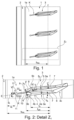
- Fig. 1 shows a circumferential section of a shoulder-side tread rib 1.
- the lateral edge of the ground contact patch (determined with a tyre mounted on a standard rim, loaded at 70% of the maximum load capacity, internal pressure 85% of the standard pressure, according to ETRTO standards) is indicated by a dashed line 1.
- the tread is preferably designed asymmetrically with respect to the tire equatorial plane, so that in the second shoulder-side tread area (not shown) a shoulder-side profile rib is formed, the design of which differs from that of the shoulder-side profile rib 1 shown, and wherein the pneumatic vehicle tire is to be mounted on a vehicle in such a way that the shoulder-side profile rib 1 shown is assigned to the inside of the vehicle.
- the shoulder-side profile rib 1 has a profile rib outer surface 1a located on the tread periphery and a width b PR determined within the ground contact area, on the tread periphery in the axial direction and is surrounded on the tread inside by a Fig. 1 merely indicated, in the shown Embodiment in plan view, the shoulder-side circumferential groove 2 is straight and is designed in the respective intended tread depth, which for passenger cars, vans or light trucks is usually 6.5 mm to 8.5 mm.
- the shoulder-side profile rib 1 is provided over its circumferential extent with a plurality of shoulder-side transverse grooves 3 which run parallel to one another in plan view, which extend beyond the lateral edge (line 1) of the ground contact surface and end on the inside of the tread within the shoulder-side profile rib 1 at a distance determined in the axial direction in front of the shoulder-side circumferential groove 2.
- a channel-cut combination K formed in the shoulder-side profile rib 1 adjoins the inside of the tread end of each transverse groove 3.
- Fig. 2 is the channel-cut combination K, the design of which will be discussed in more detail later, with respect to a plane E which extends from a straight line g 1 running in plan view to the axial direction at an angle ⁇ of 0° to 10°, in particular of 2° to 7°, and a straight line g 2 running in the radial direction ( Fig. 3 ) is spanned, is symmetrical.
- the transverse groove 3 is designed in such a way that the plane E, viewed in plan view, passes through the transverse groove 3 in its longitudinal extension, so that the plane E defines the direction of extension of the transverse groove 3.
- the transverse groove 3 has, within the ground contact surface, a length 1 QR , determined on the profile rib outer surface 1a, related to the plane E, projected in the axial direction, of 45% to 65%, in particular 50% to 60%, of the width b PR of the shoulder-side profile rib 1.
- the transverse groove 3 viewed in plan view, is made up of a main section 3a, which runs partially inside and partially outside the ground contact surface, a tapered shoulder section 3c located outside the ground contact surface, and a tapered section 3b adjoining the end of the main section 3a on the inside of the tread. Furthermore, the transverse groove 3 has The profile rib outer surface 1a has two groove edges 4, 5 which extend beyond the ground contact surface and which each extend over the main section 3a, the tapered section 3b and the shoulder section 3c.
- the groove edges 4, 5 have an edge section 4a or 5a running in the main section 3a and an edge section 4b or 5b running in the tapered section 3b.
- the edge sections 4a, 5a run straight when viewed from above and at an angle ⁇ (edge section 4a) or ⁇ ' (edge section 5a) to the axial direction, wherein the angles ⁇ , ⁇ ' are each 0° to 10°, in particular 2° to 7°, and wherein the edge sections 4a, 5a in the embodiment shown are inclined in the same direction to one another with respect to the axial direction.
- the edge sections 4b, 5b also run straight when viewed from above and at an angle ⁇ (edge section 4b) or ⁇ ' (edge section 5b) to the axial direction, wherein the angles ⁇ , ⁇ ' are each 15° to 30° and wherein the edge sections 4b, 5b are inclined in opposite directions to one another with respect to the axial direction such that they approach one another in the direction of the shoulder-side circumferential groove 2.
- the angle ⁇ and the angle ⁇ ' can deviate from one another by up to 10° in particular.
- the main section 3a has - within the ground contact area - a length l a determined on the profile rib outer surface 1a, related to the plane E, projected in the axial direction of 70% to 90%, in particular 75% to 80%, of the length l QR of the transverse groove 3, a maximum depth t a determined in the radial direction ( Fig. 4 ) of 75% to 100%, in particular of a maximum of 95%, of the tread depth and a width b a of 3.0 mm to 7.0 mm, determined as the smallest possible distance between the edge section 4a and the edge section 5a.
- the length l a is further related to the end of the edge section 4a, 5a on the inside of the tread which is further on the inside of the tread.
- the main section 3a is delimited by a groove base 6 and two groove flanks 7, one of which starts from the edge section 4a and the other from the edge section 5a, and which, viewed in cross-section perpendicular to the associated edge section 4a, 5a, run at an angle of 0° to 5° to the radial direction.
- the tapering section 3b narrows at the level of the profile rib outer surface 1a starting from the main section 3a continuously in the direction to the shoulder-side circumferential groove 2 and has a width b b of 1.5 mm to 3.0 mm, preferably of at most 2.0 mm, measured between the tread-side ends of the edge sections 4b and 5b.
- the lateral flanks 8 extend from the edge sections 4b, 5b, adjoin the groove flanks 7 and, viewed in cross-section perpendicular to the associated edge section 4b, 5b, run at an angle of 0° to 5°, in particular of at least 2°, to the radial direction.
- the end flank 9 extends between the flanks 8, adjoins the groove base 6 and continues thereto as far as the profile rib outer surface 1a.
- the end flank 9 is composed of a radially inner end flank section 9a directly adjacent to the groove base 6 and a radially outer end flank section 9b.
- the radially inner end flank section 9a viewed in the cross section lying in plane E (cf. position of section line VI-VI in Fig. 2 ) in the shape of a circular arc and adjoins the groove base 6 without kinks.
- the radially outer end flank section 9b viewed in the cross-section projected into the plane E, runs straight to the radial direction and at an angle ⁇ of 0° to 10°, in particular of 3° to 7°.
- the already mentioned channel-incision combination K is formed from a tubular channel 11 with a circular cross-section and an incision 10 opening into this, wherein the incision 10 and the channel 11 jointly open into the tapering section 3b of the transverse groove 3 and wherein - in accordance with the mentioned symmetrical design of the channel-incision combination K - both the channel 11 and the incision 10 with respect to the plane E (cf. Fig. 2 and Fig. 3 ) are symmetrical.
- the incision 10 starts from the profile rib outer surface 1a, runs in the radial direction into the interior of the shoulder-side profile rib 1, opens into the tapered section 3b via the radially outer end flank section 9b and has two incision walls 10a aligned in the radial direction and a constant width b E ( Fig. 3 ) from 0.4 mm to 1.2 mm, in particular from 0.6 mm to 1.0 mm, with the width b E being smaller is designed as the already mentioned width b b ( Fig. 2 ).
- the tubular channel 11 runs between the profile rib outer surface 1a and the tapered section 3b, the channel 11 being formed in the interior of the profile rib 1 over its entire extent adjacent to the incision 10, so that it surrounds the incision 10, viewed in the cross-section lying in the plane E ( Fig. 6 ), which runs in an L-shape.
- the channel 11 is composed of a channel section 11a, a middle channel section 11b and a tapering channel end section 11c.
- the channel section 11a extends from the profile rib outer surface 1a, has a circular channel opening 11' on it, forms the shorter L-beam of the L-shape, runs slightly curved, in particular semi-U-shaped, when viewed in the cross-section lying in the plane E ( Fig. 6 ), and has a diameter d k ( Fig. 6 ) from 170% to 300%, in particular from 220% to 280%, preferably from 240% to 260%, the width b E ( Fig. 3 ) of the incision 10.
- the channel opening 11' has a distance a 1 ( Fig.
- the channel section 11b and the channel end section 11c run radially within the incision 10, form the longer L-beam of the L-shape and also form a rotational body with a main axis a k ( Fig. 6 ), which in the radial direction have a depth t k of 45% to 75%, in particular 50% to 70%, particularly preferably 55% to 65%, of the maximum depth t a ( Fig. 4 ) of the main section 3a of the transverse groove 3.
- the channel section 11b also has the above -mentioned diameter d k and also a length l b ( Fig. 6 ).
- the channel end section 11c is designed in the form of a truncated cone, has a channel opening 11" located on the radially outer end flank section 9b of the end flank 9 of the transverse groove 3 and a length l c ( Fig. 6 ), wherein the length l c is 30% to 70%, in particular 40% to 60%, preferably 45% to 55%, of the length l b ( Fig. 6 ).
- the channel end section 11c narrows continuously from the channel section 11b to the tapering section 3b of the transverse groove 3, has the diameter d k at the channel section 11b and Channel opening 11" a diameter d k * ( Fig. 5 ) of 95% to 105%, in particular of 100%, of the width b E of the incision 10.
- the tapered section 3b and the shoulder section 3c of the transverse groove 3 are optional, whereby in this embodiment the main section 3a of the transverse groove 3 is preferably continued on the outside of the tread, i.e. is extended.
- the transverse groove 3 can be provided with bevels (beveled surfaces) on the groove flanks, in particular in a known manner.
- further transverse grooves can be provided in the shoulder-side profile rib.
- the tread can also have a shoulder-side profile rib in each shoulder, which is designed as described.
Landscapes
- Engineering & Computer Science (AREA)
- Mechanical Engineering (AREA)
- Tires In General (AREA)
Description
- Die Erfindung betrifft einen Fahrzeugluftreifen mit einem Laufstreifen mit zumindest einer von einer Umfangsrille begrenzten schulterseitigen Profilrippe mit einer in der Laufstreifenperipherie liegenden Profilrippenaußenfläche, wobei die schulterseitige Profilrippe mit einer Vielzahl von in Draufsicht parallel zueinander verlaufenden, vor der Umfangsrille endenden Querrillen mit jeweils einem Rillengrund und einer laufstreifeninnenseitig an den Rillengrund anschließenden und in Fortsetzung zu diesem zur Profilrippenaußenfläche verlaufenden Endflanke versehen sind.
- Ein derartiger Fahrzeugluftreifen ist beispielsweise aus der gattungsbildenden
EP 3 628 510 A1 bekannt. Der Fahrzeugluftreifen weist einen Laufstreifen mit einer schulterseitigen Profilrippe mit Querrillen auf, wobei die Querrillen einen Hauptabschnitt und einen laufstreifeninnenseitig an den Hauptabschnitt anschließenden, zur Profilrippenaußenfläche auslaufenden Auslaufabschnitt aufweisen. Der Auslaufabschnitt ist schmäler ausgeführt als der Hauptabschnitt, wobei die eine Rillenflanke der Querrille am Auslaufabschnitt endet und die andere Rillenflanke der Querrille im Auslaufabschnitt fortgeführt ist. Die im Auslaufabschnitt fortgeführte Rillenflanke liegt eine Flanke gegenüber, welche zumindest abschnittsweise zur Profilrippenaußenfläche mit einer Fase versehen ist. Die Fase weist an der Profilrippenaußenfläche eine Fasenkante auf, welche an die Rillenkante der am Auslaufabschnitt endenden Rillenflanke anschließt. Derart ausgeführte Querrillen reduzieren den Beitrag der schulterseitigen Profilrippe zum Abrollgeräusch, wobei weiterhin eine gute Wasserableitung auf nassen Untergrund sichergestellt ist. - Aus der
EP 0 625 436 A1 ist ein Fahrzeugluftreifen mit einem Laufstreifen mit Profilblöcken bekannt, die jeweils mit einer Kanal-Einschnitt-Kombination versehen sind, wobei der Kanal an unterschiedlichen Profilblockbereichen nach außen mündet. Der Kanal kann den Einschnitt beispielsweise L-förmig umlaufen und eine an der Laufstreifenperipherie liegende Kanalöffnung aufweisen. Die Kanäle erhöhen das Wasserableitvermögen und sollen zu einer Verringerung des Reifen-Fahrbahn-Geräusches beitragen. - Die
EP 3 628 511 A1 offenbart einen Fahrzeugluftreifen mit einem Laufstreifen mit einer schulterseitigen Profilrippe mit Querrillen, welche vor der die schulterseitige Profilrippe begrenzenden Umfangsrille in einem in axialer Richtung ermittelten Abstand von 3,0 mm bis 10,0 mm enden. Zu den Querrillen gehören erste Querrillen und zweite Querrillen, wobei der Abstand der ersten Querrillen zur Umfangsrille kleiner ist als der Abstand der zweiten Querrillen zur Umfangsrille und wobei in Umfangsrichtung eine erste Querrille abwechselnd auf eine zweite Querrille folgt. In der schulterseitigen Profilrippe ist bei jeder zweiten Querrille je eine von der Umfangsrille ausgehende zur Laufstreifenperipherie offene Vertiefung ausgebildet. Eine solche Profilrippe wird - unter Aufrechterhaltung einer hohen Steifigkeit - beim Fahren auf nasser Fahrbahn gut entwässert. - Die
EP 3 456 552 A1 offenbart einen Fahrzeugluftreifen, welcher insbesondere als Rennreifen für mehrspurige Kraftfahrzeuge vorgesehen ist und welcher einen Laufstreifen mit einer zentralen Profilrippe und zwei von der zentralen Profilrippe durch je eine Umfangsrille getrennte, relativ breit ausgeführte, schulterseitige Profilrippen aufweist. In den schulterseitigen Profilrippen sind erste Querrillen und zweite Querrillen ausgebildet, wobei die ersten Querrillen zur jeweiligen Umfangsrille einen kleineren Abstand aufweisen als die zweiten Querrillen und wobei in Umfangsrichtung eine erste Querrille abwechselnd auf eine zweite Querrille folgt. Ferner ist jede schulterseitige Profilrippe bei jeder zweiten Querrille mit einer lokalen, rillenförmigen Vertiefung versehen, welche beidseitig geschlossen in der schulterseitigen Profilrippe endet und die Nässeperformance verbessern soll. - Die in schulterseitigen Profilrippen ausgebildeten Querrillen unterstützen beim Fahren auf nasser Fahrbahn die Entwässerung des Laufstreifens, was vor allem für das Aquaplaningverhalten des Reifens wichtig ist, und stellen Griffkanten an der Profilrippenaußenfläche zur Verfügung, welche zur Verbesserung des Nassgriffeigenschaften beitragen. In schulterseitigen Profilrippen befindliche Querrillen spielen somit eine entscheidende Rolle im Hinblick auf die Nässeperformance des Fahrzeugluftreifens. Die Ausgestaltung von Querrillen hat dabei insbesondere unter Berücksichtigung der durch die Querrillen bedingten reduzierten Kontaktfläche der Profilrippe zum Untergrund und der reduzierten Steifigkeit der Profilrippe zu erfolgen, da eine große Kontaktfläche und eine hohe Steifigkeit für die Trockenperformance des Fahrzeugluftreifens, beispielsweise für die Handlingeigenschaften, von Vorteil sind. Die Nässe- und die Trockenperformance sollen dabei insbesondere über den Laufstreifenabrieb erhalten bleiben.
- Der Erfindung liegt daher die Aufgabe zugrunde, bei einem Fahrzeugluftreifen der eingangs genannten Art die Balance zwischen der Nässe- und der Trockenperformance zu optimieren.
- Gelöst wird die gestellte Aufgabe erfindungsgemäß dadurch, dass Querrillen vorgesehen sind, bei welchen jeweils innerhalb der schulterseitigen Profilrippe eine über die Endflanke in die jeweilige Querrille einmündende Kanal-Einschnitt-Kombination aus einem von der Profilrippenaußenfläche ausgehenden Einschnitt mit einer Breite von 0,4 mm bis 1,2 mm und einem von der Profilrippenaußenfläche ausgehenden, rohrförmigen Kanal ausgebildet ist, wobei der rohrförmige Kanal über seine gesamte Erstreckung an den Einschnitt angrenzt und diesen L-förmig umläuft, wobei der Kanal einen sich zur Endflanke verjüngenden Kanalendabschnitt aufweist.
- Beim Abrollen des Reifens bewirkt der Kontakt des Laufstreifens mit dem Untergrund ein Öffnen der Einschnitte, sodass beim Fahren auf nasser Fahrbahn Wasser über die Einschnitte sowie über die an der Profilrippenaußenfläche liegende Kanalöffnung des rohrförmigen Kanals aufgenommen wird. Da in den Einschnitt fließendes Wasser in den rohrförmigen Kanal und über dessen sich verjüngenden Kanalendabschnitt auf beschleunigte Weise in die Querrille abgeleitet wird, stellt die erfindungsgemäß vorgesehene Einschnitt-Kanal-Kombination eine wirkungsvolle Entwässerung der schulterseitigen Profilrippe in Richtung zur Laufstreifenschulter sicher, sodass eine gute Nässeperformance gewährleistet ist. Die Querrillen sind gegenüber üblichen Querrillen im Bereich der Bodenaufstandsfläche kürzer ausgeführt, sodass die Kontaktfläche und die Steifigkeit der schulterseitigen Profilrippe vergrößert und derart die Trockenperformance optimiert ist.
- Gemäß einer bevorzugten Ausführung weist der Kanal außerhalb des Kanalendabschnittes einen Durchmesser von 170% bis 300%, insbesondere von 220% bis 280%, bevorzugt von 240% bis 260%, der Breite des Einschnittes auf. Diese Maßnahme ist für das Wasserdrainagevermögen des Kanals und daher für die Nässeperformance des Reifens zusätzlich von Vorteil.
- Ein besonders verwirbelungsarmes Ausströmen des Wassers aus dem Kanal in die Querrille ist sichergestellt, wenn der Kanalendabschnitt die Form eines Kegelstumpfes aufweist.
- Gemäß einer weiteren bevorzugten Ausführung weist der Kanalendabschnitt an der Endflanke einen Durchmesser von 95% bis 105%, insbesondere von 100%, der Breite des Einschnittes auf. Dies begünstigt eine beschleunigte Ableitung des Wassers aus dem Kanal in die Querrille.
- Gemäß einer weiteren bevorzugten Ausführung setzt sich der Kanal aus dem Kanalendabschnitt, einem von der Profilrippenaußenfläche ausgehenden Kanalabschnitt und einem mittleren Kanalabschnitt zusammen, wobei der Kanalendabschnitt mit dem mittleren Kanalabschnitt den längeren L-Balken der L-Form und der Kanalabschnitt, welcher von der Profilrippenaußenfläche ausgeht, den kürzeren L-Balken der L-Form bildet. Dies trägt zu einer weiteren Verbesserung des Wasserableitvermögens der Kanal-Einschnitt-Kombination und derart zu einer weiteren Verbesserung der Nässeperformance bei.
- Weitere Ausgestaltungen tragen dazu bei, die letztgenannte bevorzugte Ausführung im Hinblick auf die Nässeperformance noch weiter zu verbessern.
- Eine dieser Ausgestaltungen besteht darin, dass der mittlere Kanalabschnitt und der Kanalendabschnitt einen gemeinsamen Rotationskörper mit einer Hauptachse bilden. Dies trägt zu einer verwirbelungsarmen Wasserströmung im Kanal bei.
- Dabei ist es von Vorteil, wenn die Hauptachse des gemeinsamen Rotationskörpers, welcher vom Kanalendabschnitt und dem mittleren Kanalabschnitt gebildet ist, in einer in radialer Richtung ermittelten Tiefe von 45% bis 75%, insbesondere von 50% bis 70%, besonders bevorzugt von 55% bis 65%, der maximalen Tiefe der Querrille verläuft. Diese Maßnahme trägt ferner dazu bei, dass eine hohe Steifigkeit der schulterseitigen Profilrippe im Bereich des Kanals erhalten bleibt und ist somit auch für die Trockenperformance von Vorteil.
- Ferner ist es dieser Ausgestaltung günstig, wenn der mittlere Kanalabschnitt und der Kanalendabschnitt jeweils eine entlang der Hauptachse ermittelte Länge aufweisen, wobei die Länge des Kanalendabschnittes 30% bis 70%, insbesondere 40% bis 60%, bevorzugt 45% bis 55%, der Länge des mittleren Kanalabschnittes beträgt. Ein solcher Kanal ist vor allem im Hinblick auf seine Wasseraufnahmekapazität als auch im Hinblick auf sein Wasserdrainageverhalten besonders vorteilhaft.
- Gemäß einer weiteren bevorzugten Ausführung weist der Kanal an der Profilrippenaußenfläche eine Kanalöffnung auf, die zur schulterseitigen Umfangsrille einen Abstand von 2,0 mm bis 8,0 mm, insbesondere von bis zu 5,0 mm, aufweist, wobei der Abstand als kleinstmöglicher Abstand zwischen der schulterseitigen Umfangsrille und dem Lochkreis der radial äußeren Kanalöffnung ermittelt ist.
- Eine weitere, insbesondere für die Nässeperformance günstige Ausführung ist dadurch gekennzeichnet, dass die Kanal-Einschnitt-Kombination bezüglich einer Ebene, welche von einer in Draufsicht zur axialen Richtung unter einem Winkel von 0° bis 10°, insbesondere von 2° bis 7°, verlaufenden Geraden und einer in radialer Richtung verlaufenden Geraden aufgespannt ist, symmetrisch ausgebildet ist.
- Bei dieser Ausführung ist es von Vorteil, wenn die Ebene die Querrille, in Draufsicht betrachtet, in ihrer Längserstreckung durchquert. Dies ist für die Wasserableitung von der Einschnitt-Kanal-Kombination in die Querrille sowie die Weiterleitung des Wassers in den Bereich außerhalb der Bodenaufstandsfläche günstig.
- Ferner ist es bei dieser Ausführung von Vorteil, wenn sich die Endflanke der Querrille aus einem unmittelbar an den Rillengrund anschließenden, radial inneren Endflankenabschnitt und einem zur Profilrippenaußenfläche verlaufenden radial äußeren Endflankenabschnitt, über welchen die Einschnitt-Kanal-Kombination in die Querrille einmündet, zusammensetzt, wobei der radial äußere Endflankenabschnitt, im in die Ebene projizierten Querschnitt betrachtet, zur radialen Richtung unter einem Winkel von 0° bis 10°, insbesondere von 3° bis 7°, verläuft und wobei der radial innere Endflankenabschnitt, im in der Ebene liegenden Querschnitt betrachtet, kreisbogenförmig verläuft und knickfrei an den Rillengrund anschließt. Der radial äußere Endflankenabschnitt hat eine abstützende Wirkung auf die Querrille, versteift die Querrille und somit die schulterseitige Profilrippe lokal, was im Hinblick auf die Trockenperformance günstig ist. Der kreisbogenförmig verlaufende radial innere Flankenabschnitt trägt zu einem verwirbelungsarmen Wasserfluss vom Kanal in die Querrille bei. Diese Ausführung ist daher für die Balance zwischen der Nässe- und der Trockenperformance von besonderem Vorteil.
- Gemäß einer weiteren bevorzugten Ausführung weist die Querrille, in Draufsicht betrachtet, einen abschnittweise innerhalb und abschnittsweise außerhalb der Bodenaufstandsfläche verlaufenden Hauptabschnitt und einen an das laufstreifeninnenseitige Ende des Hauptabschnittes anschließenden Verjüngungsabschnitt, in welchem die Endflanke ausgebildet ist und welcher sich an der Profilrippenaußenfläche vom Hauptabschnitt zum Einschnitt kontinuierlich verschmälert, auf. Der Verjüngungsabschnitt trägt zu einem verwirbelungsarmen Wasserfluss von der Kanal-Einschnitt-Kombination in den Hauptabschnitt bei. Der Hauptabschnitt ist für die Entwässerungsleistung der Querrille von Vorteil.
- In diesem Zusammenhang ist es ferner von Vorteil, wenn der Hauptabschnitt innerhalb der Bodenaufstandsfläche an der Profilrippenaußenfläche eine Breite von 3,0 mm bis 7,0 mm aufweist.
- Der Verjüngungsabschnitt weist am Niveau der Profilrippenaußenfläche an seinem laufstreifeninnenseitigen Ende eine Breite von 1,5 mm bis 3,0 mm, vorzugsweise von höchstens 2,0 mm, auf.
- Weitere Merkmale, Vorteile und Einzelheiten der Erfindung werden nun anhand der Zeichnung, die schematisch ein Ausführungsbeispiel der Erfindung zeigt, näher erläutert. Dabei zeigen
-
Fig. 1 eine Draufsicht auf einen Umfangsabschnitt einer schulterseitigen Profilrippe eines Laufstreifens eines Fahrzeugluftreifens mit einer Ausführungsvariante der Erfindung, -
Fig. 2 eine vergrößerte Draufsicht auf das Detail Z2 derFig. 1 , -
Fig. 3 einen vergrößerten Schnitt entlang der Linie III-III derFig. 2 , -
Fig. 4 eine Detailansicht gemäß der inFig. 2 durch den Peil S4 angedeuteten Sichtrichtung, -
Fig. 5 eine entlang der Linie V-V derFig. 2 aufgeschnittene, vergrößerte Schrägansicht und -
Fig. 6 einen vergrößerten Schnitt entlang der Linie VI-VI derFig. 2 . - Gemäß der Erfindung ausgeführte Fahrzeugluftreifen sind Reifen für Kraftfahrzeuge, insbesondere für mehrspurige Kraftfahrzeuge, sowie vorzugsweise Reifen in Radialbauart für Personenkraftwagen, Vans oder Light-Trucks (Leichte LKWs mit zGM ≤ 7,5 t).
-
Fig. 1 zeigt einen Umfangsabschnitt einer schulterseitigen Profilrippe 1. Der seitliche Rand der Bodenaufstandsfläche (ermittelt mit einem auf einer Normfelge montierten Reifen, Last bei 70 % der maximalen Tragfähigkeit, Innendruck 85 % des Normdruckes, gemäß ETRTO-Standards) ist durch eine gestrichelte Linie 1 gekennzeichnet. - Der Laufstreifen ist - bezogen auf die Reifenäquatorialebene - vorzugsweise asymmetrisch ausgeführt, sodass im zweiten, nicht gezeigten schulterseitigen Laufstreifenbereich eine schulterseitige Profilrippe ausgebildet ist, deren Ausgestaltung von jener der gezeigten schulterseitigen Profilrippe 1 abweicht und wobei der Fahrzeugluftreifen derart auf einem Fahrzeug zu montieren ist, dass die gezeigte schulterseitige Profilrippe 1 der Fahrzeuginnenseite zugeordnet ist.
- Die schulterseitige Profilrippe 1 weist eine an der Laufstreifenperipherie liegende Profilrippenaußenfläche 1a sowie eine innerhalb der Bodenaufstandsfläche, an der Laufstreifenperipherie in axialer Richtung ermittelte Breite bPR auf und ist laufstreifeninnenseitig von einer in
Fig. 1 lediglich angedeuteten, beim gezeigten Ausführungsbeispiel in Draufsicht gerade verlaufenden, schulterseitigen Umfangsrille 2 begrenzt, welche in der jeweils vorgesehenen Profiltiefe ausgeführt ist, die für Personenkraftwagen, Vans oder Light-Trucks üblicherweise 6,5 mm bis 8,5 mm beträgt. - Ferner ist die schulterseitige Profilrippe 1 über ihre Umfangserstreckung mit einer Vielzahl von in Draufsicht parallel zueinander verlaufenden schulterseitigen Querrillen 3 versehen, welche über den seitlichen Rand (Linie 1) der Bodenaufstandsfläche hinausverlaufen und laufstreifeninnenseitig innerhalb der schulterseitigen Profilrippe 1 in einem in axialer Richtung ermittelten Abstand vor der schulterseitigen Umfangsrille 2 enden. An das laufstreifeninnenseitige Ende jeder Querrille 3 schließt eine in der schulterseitigen Profilrippe 1 ausgebildete Kanal-Einschnitt-Kombination K an.
- Die weitere Ausgestaltung der schulterseitigen Querrillen 3 wird nachfolgend anhand einer einzelnen Querrille 3 mit zugehöriger Kanal-Einschnitt-Kombination K sowie unter Bezugnahme auf
Fig. 2 bis Fig. 6 erläutert. - Gemäß
Fig. 2 ist die Kanal-Einschnitt-Kombination K, auf deren Ausgestaltung später noch im Detail eingegangen wird, bezüglich einer Ebene E, welche von einer in Draufsicht zur axialen Richtung unter einem Winkel γ von 0° bis 10°, insbesondere von 2° bis 7°, verlaufenden Geraden g1 und einer in radialer Richtung verlaufenden Geraden g2 (Fig. 3 ) aufgespannt ist, symmetrisch ausgebildet. - Die Querrille 3 ist derart ausgeführt, dass die Ebene E, in Draufsicht betrachtet, die Querrille 3 in ihrer Längserstreckung durchquert, sodass die Ebene E die Erstreckungsrichtung der Querrille 3 definiert. Die Querrille 3 weist innerhalb der Bodenaufstandsfläche, eine an der Profilrippenaußenfläche 1a ermittelte, auf die Ebene E bezogene, in die axiale Richtung projizierte Länge 1QR von 45% bis 65%, insbesondere von 50% bis 60%, der Breite bPR der schulterseitigen Profilrippe 1 auf. Die Querrille 3 setzt sich, in Draufsicht betrachtet, aus einem abschnittweise innerhalb und abschnittsweise außerhalb der Bodenaufstandsfläche verlaufenden Hauptabschnitt 3a, einem außerhalb der Bodenaufstandsfläche befindlichen, auslaufenden Schulterabschnitt 3c und einem an das laufstreifeninnenseitige Ende des Hauptabschnittes 3a anschließenden Verjüngungsabschnitt 3b zusammen. Ferner weist die Querrille 3 an der Profilrippenaußenfläche 1a zwei über die Bodenaufstandsfläche hinausverlaufende Rillenkanten 4, 5 auf, welche jeweils über den Hauptabschnitt 3a, den Verjüngungsabschnitt 3b und den Schulterabschnitt 3c verlaufen.
- Die Rillenkanten 4, 5 weisen einen im Hauptabschnitt 3a verlaufenden Kantenabschnitt 4a bzw. 5a und einem im Verjüngungsabschnitt 3b verlaufenden Kantenabschnitt 4b bzw. 5b auf. Die Kantenabschnitte 4a, 5a verlaufen in Draufsicht betrachtet gerade sowie zur axialen Richtung unter einem Winkel α (Kantenabschnitt 4a) bzw. α' (Kantenabschnitt 5a), wobei die Winkel α, α' jeweils 0° bis 10°, insbesondere 2° bis 7°, betragen und wobei die Kantenabschnitte 4a, 5a beim gezeigten Ausführungsbeispiel bezüglich der axialen Richtung gleichsinnig zueinander geneigt sind. Die Kantenabschnitte 4b, 5b verlaufen in Draufsicht betrachtet ebenfalls gerade sowie zur axialen Richtung unter einem Winkel β (Kantenabschnitt 4b) bzw. β' (Kantenabschnitt 5b), wobei die Winkel β, β' jeweils 15° bis 30° betragen und wobei die Kantenabschnitte 4b, 5b bezüglich der axialen Richtung derart gegensinnig zueinander geneigt sind, dass sie sich in Richtung zur schulterseitigen Umfangsrille 2 aneinander annähern. Der Winkel β und der Winkel β' können um insbesondere bis zu 10° voneinander abweichen.
- Der Hauptabschnitt 3a weist - jeweils innerhalb der Bodenaufstandsfläche - eine an der Profilrippenaußenfläche 1a ermittelte, auf die Ebene E bezogene, in die axiale Richtung projizierte Länge la von 70% bis 90%, insbesondere von 75% bis 80%, der Länge lQR der Querrille 3, eine in radialer Richtung ermittelte maximale Tiefe ta (
Fig. 4 ) von 75% bis 100%, insbesondere von höchstens 95%, der Profiltiefe und eine als kleinstmöglichen Abstand zwischen dem Kantenabschnitt 4a und dem Kantenabschnitt 5a ermittelte Breite ba von 3,0 mm bis 7,0 mm auf. Die Länge la ist dabei ferner auf das laufstreifeninnenseitige Ende jenes Kantenabschnittes 4a, 5a bezogen, welches weiter laufstreifeninnenseitig liegt. Der Hauptabschnitt 3a ist durch einen Rillengrund 6 und zwei Rillenflanken 7, von welchen die eine vom Kantenabschnitt 4a und die andere vom Kantenabschnitt 5a ausgeht, und welche, im Querschnitt senkrecht zum zugehörigen Kantenabschnitt 4a, 5a betrachtet, zur radialen Richtung unter einem Winkel von 0° bis 5° verlaufen, begrenzt. - Der Verjüngungsabschnitt 3b verschmälert sich am Niveau an der Profilrippenaußenfläche 1a ausgehend vom Hauptabschnitt 3a kontinuierlich in Richtung zur schulterseitigen Umfangsrille 2 und weist ermittelt zwischen den laufstreifeninnenseitigen Enden der Kantenabschnitte 4b und 5b eine Breite bb von 1,5 mm bis 3,0 mm, vorzugsweise von höchstens 2,0 mm, auf. Wie
Fig. 2 insbesondere in Kombination mitFig. 4 zeigt, ist der Verjüngungsabschnitt 3b durch zwei seitliche Flanken 8 und eine Endflanke 9 begrenzt. Die seitlichen Flanken 8 gehen von den Kantenabschnitten 4b, 5b aus, schließen an den Rillenflanken 7 an und verlaufen, im Querschnitt senkrecht zum zugehörigen Kantenabschnitt 4b, 5b betrachtet, zur radialen Richtung unter einem Winkel von 0° bis 5°, insbesondere von zumindest 2°. Die Endflanke 9 erstreckt sich zwischen den Flanken 8, schließt an den Rillengrund 6 an und verläuft in Fortsetzung zu diesem bis zur Profilrippenaußenfläche 1a. - Gemäß
Fig. 4 undFig. 6 setzt sich die Endflanke 9 aus einem unmittelbar an den Rillengrund 6 anschließenden, radial inneren Endflankenabschnitt 9a und einem radial äußeren Endflankenabschnitt 9b zusammen. WieFig. 6 zeigt, verläuft der radial innere Endflankenabschnitt 9a, im in der Ebene E liegenden Querschnitt betrachtet (vergl. Lage der Schnittlinie VI-VI inFig. 2 ) kreisbogenförmig und schließt knickfrei an den Rillengrund 6 an. Der radial äußere Endflankenabschnitt 9b verläuft, im in die Ebene E projizierten Querschnitt betrachtet, zur radialen Richtung gerade sowie unter einem Winkel δ von 0° bis 10°, insbesondere von 3° bis 7°. - Wie
Fig. 4 bis Fig. 6 insbesondere in Verbindung zeigen, ist die bereits erwähnte Kanal-Einschnitt-Kombination K aus einem rohrförmigen Kanal 11 mit einem kreisförmigen Querschnitt und einem in diesen einmündenden Einschnitt 10 gebildet, wobei der Einschnitt 10 und der Kanal 11 gemeinsam in den Verjüngungsabschnitt 3b der Querrille 3 einmünden und wobei - entsprechend der erwähnten symmetrischen Ausgestaltung der Kanal-Einschnitt-Kombination K - sowohl der Kanal 11 als auch der Einschnitt 10 bezüglich der Ebene E (vergl.Fig. 2 undFig. 3 ) symmetrisch ausgeführt sind. - Der Einschnitt 10 geht von der Profilrippenaußenfläche 1a aus, verläuft in radialer Richtung ins Innere der schulterseitigen Profilrippe 1 hinein, mündet über den radial äußeren Endflankenabschnitt 9b in den Verjüngungsabschnitt 3b ein und weist zwei in radialer Richtung ausgerichtete Einschnittwände 10a sowie eine konstante Breite bE (
Fig. 3 ) von 0,4 mm bis 1,2 mm, insbesondere von 0,6 mm bis 1,0 mm, auf, wobei die Breite bE kleiner ausgeführt ist als die bereits erwähnte, zum Verjüngungsabschnitt 3b gehörende Breite bb (Fig. 2 ). - Gemäß
Fig. 5 und Fig. 6 verläuft der rohrförmige Kanal 11 zwischen der Profilrippenaußenfläche 1a und dem Verjüngungsabschnitt 3b, wobei der Kanal 11 im Inneren der Profilrippe 1 über seine gesamte Erstreckung an den Einschnitt 10 angrenzend ausgebildet ist, sodass er den Einschnitt 10, im in der Ebene E liegenden Querschnitt betrachtet (Fig. 6 ), L-förmig umläuft. - Der Kanal 11 setzt sich aus einem Kanalabschnitt 11a, einem mittleren Kanalabschnitt 11b und einem sich verjüngenden Kanalendabschnitt 11c zusammen. Der Kanalabschnitt 11a geht von der Profilrippenaußenfläche 1a aus, weist an dieser eine kreisförmige Kanalöffnung 11' auf, bildet den kürzeren L-Balken der L-Form, verläuft, im in der Ebene E liegenden Querschnitt betrachtet, leicht gebogen, insbesondere halb-U-förmig gebogen (
Fig. 6 ), und weist einen Durchmesser dk (Fig. 6 ) von 170% bis 300%, insbesondere von 220% bis 280%, bevorzugt von 240% bis 260%, der Breite bE (Fig. 3 ) des Einschnittes 10 auf. Die Kanalöffnung 11' weist zur schulterseitigen Umfangsrille 2 einen Abstand a1 (Fig. 2 ) von 2,0 mm bis 8,0 mm, insbesondere von bis zu 5,0 mm auf, wobei der Abstand a1 als kleinstmöglicher Abstand zwischen der schulterseitigen Umfangsrille 2 und dem Lochkreis der Kanalöffnung 11' ermittelt ist. Der Kanalabschnitt 11b und der Kanalendabschnitt 11c verlaufen radial innerhalb des Einschnittes 10, bilden den längeren L-Balken der L-Form und bilden ferner einen Rotationskörper mit einer Hauptachse ak (Fig. 6 ), welche sich in einer in radialer Richtung Tiefe tk von 45% bis 75%, insbesondere von 50% bis 70%, besonders bevorzugt von 55% bis 65%, der maximalen Tiefe ta (Fig. 4 ) des Hauptabschnittes 3a der Querrille 3 befindet. Der Kanalabschnitt 11b weist ebenfalls den bereits erwähnten Durchmesser dk sowie ferner eine entlang der Hauptachse ak ermittelte Länge lb (Fig. 6 ) auf. Der Kanalendabschnitt 11c ist in Form eines Kegelstumpfes ausgeführt, weist eine am radial äußeren Endflankenabschnitt 9b der Endflanke 9 der Querrille 3 liegende Kanalöffnung 11" sowie eine entlang der Hauptachse ak ermittelte Länge lc (Fig. 6 ) auf, wobei die Länge lc 30% bis 70%, insbesondere 40% bis 60%, bevorzugt 45% bis 55%, der Länge lb (Fig. 6 ) beträgt. Der Kanalendabschnitt 11c verengt sich kontinuierlich ausgehend vom Kanalabschnitt 11b zum Verjüngungsabschnitt 3b der Querrille 3, weist am Kanalabschnitt 11b den Durchmesser dk und an der Kanalöffnung 11" einen Durchmesser dk* (Fig. 5 ) von 95% bis 105%, insbesondere von 100%, der Breite bE des Einschnittes 10 auf. - Die Erfindung ist auf das beschriebene Ausführungsbeispiel nicht beschränkt, sondern nur durch den Schutzumfang der Ansprüche.
- Der Verjüngungsabschnitt 3b und der Schulterabschnitt 3c der Querrille 3 sind optional, wobei bei dieser Ausführung der Hauptabschnitt 3a der Querrille 3 laufstreifenaußenseitig vorzugsweise fortgeführt, also verlängert ist. Die Querrille 3 kann an den Rillenflanken mit in insbesondere bekannter Weise ausgeführten Fasen (Schrägflächen) versehen sein. Ferner können neben den Querrillen 3 weitere Querrillen in der schulterseitigen Profilrippe vorgesehen sein. Der Laufstreifen kann ferner in jeder Schulter eine schulterseitige Profilrippe, welche wie beschrieben ausgeführt ist, aufweisen.
-
- 1
- schulterseitige Profilrippe
- 1a
- Profilrippenaußenfläche
- 2
- schulterseitige Umfangsrille
- 3
- schulterseitige Querrille
- 3a
- Hauptabschnitt
- 3b
- Verjüngungsabschnitt
- 3c
- Schulterabschnitt
- 4
- Rillenkante
- 4a
- Kantenabschnitt
- 4b
- Kantenabschnitt
- 5
- Rillenkante
- 5a
- Kantenabschnitt
- 5b
- Kantenabschnitt
- 6
- Rillengrund
- 7
- Rillenflanke
- 8
- seitliche Flanke
- 9
- Endflanke
- 9a
- radial innerer Endflankenabschnitt
- 9b
- radial äußerer Endflankenabschnitt
- 10
- Einschnitt
- 10a
- Einschnittwand
- 11
- Kanal
- 11a
- Kanalabschnitt
- 11b
- Kanalabschnitt
- 11c
- Kanalendabschnitt
- 11'
- Kanalöffnung
- 11"
- Kanalöffnung
- a1
- Abstand
- ak
- Hauptachse
- ba, bb, bE, bPR
- Breite
- dk, dk*
- Durchmesser
- E
- Ebene
- g1, g2
- Gerade
- K
- Kanal-Einschnitt-Kombination
- 1
- Linie (seitlicher Rand der Bodenaufstandsfläche)
- la, lb, lc, lQR
- Länge
- ta, tk
- maximale Tiefe
- S4
- Pfeil (Sichtrichtung)
- Z2
- Detail
- α, α', β, β', γ, δ
- Winkel
Claims (15)
- Fahrzeugluftreifen mit einem Laufstreifen mit zumindest einer von einer Umfangsrille (2) begrenzten schulterseitigen Profilrippe (1) mit einer in der Laufstreifenperipherie liegenden Profilrippenaußenfläche (1a), wobei die schulterseitige Profilrippe (1) mit einer Vielzahl von in Draufsicht parallel zueinander verlaufenden, vor der Umfangsrille (2) endenden Querrillen (3) mit jeweils einem Rillengrund (6) und einer laufstreifeninnenseitig an den Rillengrund (6) anschließenden und in Fortsetzung zu diesem zur Profilrippenaußenfläche (1a) verlaufenden Endflanke (9) versehen sind,
dadurch gekennzeichnet,
dass Querrillen (3) vorgesehen sind, bei welchen jeweils innerhalb der schulterseitigen Profilrippe (1) eine über die Endflanke (9) in die jeweilige Querrille (3) einmündende Kanal-Einschnitt-Kombination (K) aus einem von der Profilrippenaußenfläche (1a) ausgehenden Einschnitt (10) mit einer Breite (bE) von 0,4 mm bis 1,2 mm und einem von der Profilrippenaußenfläche (1a) ausgehenden, rohrförmigen Kanal (11) ausgebildet ist, wobei der rohrförmige Kanal (11) über seine gesamte Erstreckung an den Einschnitt (10) angrenzt und diesen L-förmig umläuft, wobei der Kanal (11) einen sich zur Endflanke (9) verjüngenden Kanalendabschnitt (11c) aufweist. - Fahrzeugluftreifen nach Anspruch 1, dadurch gekennzeichnet, dass der Kanal (11) außerhalb des Kanalendabschnittes (11c) einen Durchmesser (dk) von 170% bis 300%, insbesondere von 220% bis 280%, bevorzugt von 240% bis 260%, der Breite (bE) des Einschnittes (10) aufweist.
- Fahrzeugluftreifen nach Anspruch 1 oder 2, dadurch gekennzeichnet, dass der Kanalendabschnitt (11c) die Form eines Kegelstumpfes aufweist.
- Fahrzeugluftreifen nach einem der Ansprüche 1 bis 3, dadurch gekennzeichnet, dass der Kanalendabschnitt (11c) an der Endflanke (9) einen Durchmesser (dk*) von 95% bis 105%, insbesondere von 100%, der Breite (bE) des Einschnittes (10) aufweist.
- Fahrzeugluftreifen nach einem der Ansprüche 1 bis 4, dadurch gekennzeichnet, dass sich der Kanal (11) aus dem Kanalendabschnitt (11c), einem von der Profilrippenaußenfläche (1a) ausgehenden Kanalabschnitt (11a) und einem mittleren Kanalabschnitt (11b) zusammensetzt,
wobei der Kanalendabschnitt (11c) mit dem mittleren Kanalabschnitt (11b) den längeren L-Balken der L-Form und der Kanalabschnitt (11a), welcher von der Profilrippenaußenfläche (1a) ausgeht, den kürzeren L-Balken der L-Form bildet. - Fahrzeugluftreifen nach Anspruch 5, dadurch gekennzeichnet, dass der mittlere Kanalabschnitt (11b) und der Kanalendabschnitt (11c) einen gemeinsamen Rotationskörper mit einer Hauptachse (ak) bilden.
- Fahrzeugluftreifen nach Anspruch 6, dadurch gekennzeichnet, dass die Hauptachse (ak) des gemeinsamen Rotationskörpers, welcher vom Kanalendabschnitt (11c) und dem mittleren Kanalabschnitt (11b) gebildet ist, in einer in radialer Richtung ermittelten Tiefe (tk) von 45% bis 75%, insbesondere von 50% bis 70%, besonders bevorzugt von 55% bis 65%, der maximalen Tiefe (ta) der Querrille (3) verläuft.
- Fahrzeugluftreifen nach Anspruch 6 oder 7, dadurch gekennzeichnet, dass der mittlere Kanalabschnitt (11b) und der Kanalendabschnitt (11c) jeweils eine entlang der Hauptachse (ak) ermittelte Länge (lb, lc) aufweisen, wobei die Länge (lc) des Kanalendabschnittes (11c) 30% bis 70%, insbesondere 40% bis 60%, bevorzugt 45% bis 55%, der Länge (lb) des mittleren Kanalabschnittes (11b) beträgt.
- Fahrzeugluftreifen nach einem der Ansprüche 1 bis 8, dadurch gekennzeichnet, dass der Kanal (11) an der Profilrippenaußenfläche (1a) eine Kanalöffnung (11') aufweist, die zur schulterseitigen Umfangsrille (2) einen Abstand (a1) von 2,0 mm bis 8,0 mm, insbesondere von bis zu 5,0 mm, aufweist, wobei der Abstand (a1) als kleinstmöglicher Abstand zwischen der schulterseitigen Umfangsrille (2) und dem Lochkreis der radial äußeren Kanalöffnung (11') ermittelt ist.
- Fahrzeugluftreifen nach einem der Ansprüche 1 bis 9, dadurch gekennzeichnet, dass die Kanal-Einschnitt-Kombination (K) bezüglich einer Ebene (E), welche von einer in Draufsicht zur axialen Richtung unter einem Winkel (γ) von 0° bis 10°, insbesondere von 2° bis 7°, verlaufenden Geraden (g1) und einer in radialer Richtung verlaufenden Geraden (g2) aufgespannt ist, symmetrisch ausgebildet ist.
- Fahrzeugluftreifen nach Anspruch 10, dadurch gekennzeichnet, dass die Ebene (E) die Querrille (3), in Draufsicht betrachtet, in ihrer Längserstreckung durchquert.
- Fahrzeugluftreifen nach Anspruch 10 oder 11, dadurch gekennzeichnet, dass sich die Endflanke (9) der Querrille (3) aus einem unmittelbar an den Rillengrund (6) anschließenden, radial inneren Endflankenabschnitt (9a) und einem zur Profilrippenaußenfläche (1a) verlaufenden radial äußeren Endflankenabschnitt (9b), über welchen die Einschnitt-Kanal-Kombination (K) in die Querrille (3) einmündet, zusammensetzt, wobei der radial äußere Endflankenabschnitt (9b), im in die Ebene (E) projizierten Querschnitt betrachtet, zur radialen Richtung unter einem Winkel (δ) von 0° bis 10°, insbesondere von 3° bis 7°, verläuft und wobei der radial innere Endflankenabschnitt (9a), im in der Ebene (E) liegenden Querschnitt betrachtet, kreisbogenförmig verläuft und knickfrei an den Rillengrund (6) anschließt.
- Fahrzeugluftreifen nach einem der Ansprüche 1 bis 12, dadurch gekennzeichnet, dass die Querrille (3), in Draufsicht betrachtet, einen abschnittweise innerhalb und abschnittsweise außerhalb der Bodenaufstandsfläche verlaufenden Hauptabschnitt (3a) und einen an das laufstreifeninnenseitige Ende des Hauptabschnittes (3a) anschließenden Verjüngungsabschnitt (3b), in welchem die Endflanke (9) ausgebildet ist und welcher sich an der Profilrippenaußenfläche (1a) vom Hauptabschnitt (3a) zum Einschnitt (10) kontinuierlich verschmälert, aufweist.
- Fahrzeugluftreifen nach Anspruch 13, dadurch gekennzeichnet, dass der Hauptabschnitt (3a) innerhalb der Bodenaufstandsfläche an der Profilrippenaußenfläche (1a) eine Breite (ba) von 3,0 mm bis 7,0 mm aufweist.
- Fahrzeugluftreifen nach Anspruch 13 oder 14, dadurch gekennzeichnet, dass der Verjüngungsabschnitt (3b) am Niveau der Profilrippenaußenfläche (1a) an seinem laufstreifeninnenseitigen Ende eine Breite (bb) von 1,5 mm bis 3,0 mm, vorzugsweise von höchstens 2,0 mm, aufweist.
Applications Claiming Priority (2)
| Application Number | Priority Date | Filing Date | Title |
|---|---|---|---|
| US202163157040P | 2021-03-05 | 2021-03-05 | |
| PCT/EP2021/084051 WO2022184299A1 (de) | 2021-03-05 | 2021-12-02 | Fahrzeugluftreifen |
Publications (2)
| Publication Number | Publication Date |
|---|---|
| EP4301609A1 EP4301609A1 (de) | 2024-01-10 |
| EP4301609B1 true EP4301609B1 (de) | 2025-02-12 |
Family
ID=79230885
Family Applications (1)
| Application Number | Title | Priority Date | Filing Date |
|---|---|---|---|
| EP21835983.4A Active EP4301609B1 (de) | 2021-03-05 | 2021-12-02 | Fahrzeugluftreifen |
Country Status (4)
| Country | Link |
|---|---|
| US (1) | US20240157733A1 (de) |
| EP (1) | EP4301609B1 (de) |
| CN (1) | CN116963916A (de) |
| WO (1) | WO2022184299A1 (de) |
Family Cites Families (18)
| Publication number | Priority date | Publication date | Assignee | Title |
|---|---|---|---|---|
| JPH0741777B2 (ja) * | 1986-04-14 | 1995-05-10 | オ−ツタイヤ株式会社 | スタッドレス空気入りタイヤ |
| JPS63305008A (ja) * | 1987-06-03 | 1988-12-13 | Yokohama Rubber Co Ltd:The | 空気入りタイヤ |
| AT403456B (de) * | 1993-05-18 | 1998-02-25 | Semperit Ag | Fahrzeugluftreifen mit einem laufstreifen |
| JP4369729B2 (ja) * | 2003-11-13 | 2009-11-25 | 住友ゴム工業株式会社 | 空気入りタイヤ |
| US8267132B2 (en) * | 2007-10-12 | 2012-09-18 | Bridgestone Corporation | Pneumatic tire |
| JP5715655B2 (ja) * | 2013-03-22 | 2015-05-13 | 住友ゴム工業株式会社 | 空気入りタイヤ |
| DE102014210823A1 (de) * | 2014-06-06 | 2015-12-17 | Continental Reifen Deutschland Gmbh | Fahrzeugluftreifen |
| DE102014223893A1 (de) * | 2014-11-24 | 2016-05-25 | Continental Reifen Deutschland Gmbh | Fahrzeugluftreifen |
| DE102015202615A1 (de) * | 2015-02-13 | 2016-08-18 | Continental Reifen Deutschland Gmbh | Fahrzeugluftreifen |
| DE102015202614A1 (de) * | 2015-02-13 | 2016-09-01 | Continental Reifen Deutschland Gmbh | Fahrzeugluftreifen |
| JP2017193222A (ja) * | 2016-04-19 | 2017-10-26 | 横浜ゴム株式会社 | 空気入りタイヤ |
| JP6844377B2 (ja) * | 2017-03-30 | 2021-03-17 | 住友ゴム工業株式会社 | タイヤ |
| JP6897444B2 (ja) * | 2017-09-15 | 2021-06-30 | 住友ゴム工業株式会社 | タイヤ |
| DE102018208349A1 (de) * | 2018-05-28 | 2019-11-28 | Continental Reifen Deutschland Gmbh | Fahrzeugluftreifen |
| DE102018216556A1 (de) * | 2018-09-27 | 2020-04-02 | Continental Reifen Deutschland Gmbh | Fahrzeugluftreifen |
| DE102018216560A1 (de) * | 2018-09-27 | 2020-04-02 | Continental Reifen Deutschland Gmbh | Fahrzeugluftreifen |
| JP7205241B2 (ja) * | 2019-01-15 | 2023-01-17 | 住友ゴム工業株式会社 | タイヤ |
| KR102217976B1 (ko) * | 2019-08-21 | 2021-02-19 | 넥센타이어 주식회사 | 타이어 |
-
2021
- 2021-12-02 EP EP21835983.4A patent/EP4301609B1/de active Active
- 2021-12-02 US US18/548,569 patent/US20240157733A1/en active Pending
- 2021-12-02 WO PCT/EP2021/084051 patent/WO2022184299A1/de not_active Ceased
- 2021-12-02 CN CN202180095252.5A patent/CN116963916A/zh active Pending
Also Published As
| Publication number | Publication date |
|---|---|
| CN116963916A (zh) | 2023-10-27 |
| US20240157733A1 (en) | 2024-05-16 |
| EP4301609A1 (de) | 2024-01-10 |
| WO2022184299A1 (de) | 2022-09-09 |
Similar Documents
| Publication | Publication Date | Title |
|---|---|---|
| EP3589501B1 (de) | Fahrzeugluftreifen | |
| EP3589500B1 (de) | Fahrzeugluftreifen | |
| WO2009077231A1 (de) | Fahrzeugluftreifen | |
| EP3300926B1 (de) | Fahrzeugluftreifen | |
| EP3643527B1 (de) | Fahrzeugluftreifen | |
| EP4351886B1 (de) | Fahrzeugluftreifen | |
| EP3628511B1 (de) | Fahrzeugluftreifen | |
| EP3750723B1 (de) | Fahrzeugluftreifen | |
| EP3560735B1 (de) | Nutzfahrzeugreifen | |
| EP4301609B1 (de) | Fahrzeugluftreifen | |
| EP4347276B1 (de) | Fahrzeugluftreifen | |
| EP4244079B1 (de) | Fahrzeugluftreifen | |
| EP3300925B1 (de) | Fahrzeugluftreifen | |
| WO2024200185A1 (de) | Fahrzeugluftreifen | |
| EP3888951B1 (de) | Fahrzeugluftreifen | |
| EP3686034B1 (de) | Fahrzeugluftreifen | |
| EP4363243B1 (de) | Fahrzeugluftreifen | |
| EP4134249B1 (de) | Fahrzeugluftreifen | |
| EP4281296B1 (de) | Fahrzeugluftreifen | |
| EP4227116B1 (de) | Fahrzeugluftreifen | |
| EP4360914B1 (de) | Fahrzeugluftreifen | |
| EP4360913B1 (de) | Fahrzeugluftreifen | |
| EP4263241B1 (de) | Laufstreifenprofil eines fahrzeugluftreifens | |
| EP4281297B1 (de) | Fahrzeugluftreifen | |
| DE102024107982A1 (de) | Nutzfahrzeugreifen |
Legal Events
| Date | Code | Title | Description |
|---|---|---|---|
| STAA | Information on the status of an ep patent application or granted ep patent |
Free format text: STATUS: UNKNOWN |
|
| STAA | Information on the status of an ep patent application or granted ep patent |
Free format text: STATUS: THE INTERNATIONAL PUBLICATION HAS BEEN MADE |
|
| PUAI | Public reference made under article 153(3) epc to a published international application that has entered the european phase |
Free format text: ORIGINAL CODE: 0009012 |
|
| STAA | Information on the status of an ep patent application or granted ep patent |
Free format text: STATUS: REQUEST FOR EXAMINATION WAS MADE |
|
| 17P | Request for examination filed |
Effective date: 20231005 |
|
| AK | Designated contracting states |
Kind code of ref document: A1 Designated state(s): AL AT BE BG CH CY CZ DE DK EE ES FI FR GB GR HR HU IE IS IT LI LT LU LV MC MK MT NL NO PL PT RO RS SE SI SK SM TR |
|
| RAP3 | Party data changed (applicant data changed or rights of an application transferred) |
Owner name: CONTINENTAL REIFEN DEUTSCHLAND GMBH |
|
| DAV | Request for validation of the european patent (deleted) | ||
| DAX | Request for extension of the european patent (deleted) | ||
| GRAP | Despatch of communication of intention to grant a patent |
Free format text: ORIGINAL CODE: EPIDOSNIGR1 |
|
| STAA | Information on the status of an ep patent application or granted ep patent |
Free format text: STATUS: GRANT OF PATENT IS INTENDED |
|
| INTG | Intention to grant announced |
Effective date: 20240919 |
|
| GRAS | Grant fee paid |
Free format text: ORIGINAL CODE: EPIDOSNIGR3 |
|
| P01 | Opt-out of the competence of the unified patent court (upc) registered |
Free format text: CASE NUMBER: APP_63616/2024 Effective date: 20241129 |
|
| GRAA | (expected) grant |
Free format text: ORIGINAL CODE: 0009210 |
|
| STAA | Information on the status of an ep patent application or granted ep patent |
Free format text: STATUS: THE PATENT HAS BEEN GRANTED |
|
| AK | Designated contracting states |
Kind code of ref document: B1 Designated state(s): AL AT BE BG CH CY CZ DE DK EE ES FI FR GB GR HR HU IE IS IT LI LT LU LV MC MK MT NL NO PL PT RO RS SE SI SK SM TR |
|
| REG | Reference to a national code |
Ref country code: GB Ref legal event code: FG4D Free format text: NOT ENGLISH |
|
| REG | Reference to a national code |
Ref country code: CH Ref legal event code: EP |
|
| REG | Reference to a national code |
Ref country code: DE Ref legal event code: R096 Ref document number: 502021006651 Country of ref document: DE |
|
| REG | Reference to a national code |
Ref country code: IE Ref legal event code: FG4D Free format text: LANGUAGE OF EP DOCUMENT: GERMAN |
|
| REG | Reference to a national code |
Ref country code: NL Ref legal event code: FP |
|
| PG25 | Lapsed in a contracting state [announced via postgrant information from national office to epo] |
Ref country code: RS Free format text: LAPSE BECAUSE OF FAILURE TO SUBMIT A TRANSLATION OF THE DESCRIPTION OR TO PAY THE FEE WITHIN THE PRESCRIBED TIME-LIMIT Effective date: 20250512 |
|
| PG25 | Lapsed in a contracting state [announced via postgrant information from national office to epo] |
Ref country code: FI Free format text: LAPSE BECAUSE OF FAILURE TO SUBMIT A TRANSLATION OF THE DESCRIPTION OR TO PAY THE FEE WITHIN THE PRESCRIBED TIME-LIMIT Effective date: 20250212 |
|
| PG25 | Lapsed in a contracting state [announced via postgrant information from national office to epo] |
Ref country code: PL Free format text: LAPSE BECAUSE OF FAILURE TO SUBMIT A TRANSLATION OF THE DESCRIPTION OR TO PAY THE FEE WITHIN THE PRESCRIBED TIME-LIMIT Effective date: 20250212 |
|
| PG25 | Lapsed in a contracting state [announced via postgrant information from national office to epo] |
Ref country code: ES Free format text: LAPSE BECAUSE OF FAILURE TO SUBMIT A TRANSLATION OF THE DESCRIPTION OR TO PAY THE FEE WITHIN THE PRESCRIBED TIME-LIMIT Effective date: 20250212 |
|
| REG | Reference to a national code |
Ref country code: LT Ref legal event code: MG9D |
|
| PG25 | Lapsed in a contracting state [announced via postgrant information from national office to epo] |
Ref country code: IS Free format text: LAPSE BECAUSE OF FAILURE TO SUBMIT A TRANSLATION OF THE DESCRIPTION OR TO PAY THE FEE WITHIN THE PRESCRIBED TIME-LIMIT Effective date: 20250612 Ref country code: NO Free format text: LAPSE BECAUSE OF FAILURE TO SUBMIT A TRANSLATION OF THE DESCRIPTION OR TO PAY THE FEE WITHIN THE PRESCRIBED TIME-LIMIT Effective date: 20250512 |
|
| PG25 | Lapsed in a contracting state [announced via postgrant information from national office to epo] |
Ref country code: HR Free format text: LAPSE BECAUSE OF FAILURE TO SUBMIT A TRANSLATION OF THE DESCRIPTION OR TO PAY THE FEE WITHIN THE PRESCRIBED TIME-LIMIT Effective date: 20250212 |
|
| PG25 | Lapsed in a contracting state [announced via postgrant information from national office to epo] |
Ref country code: LV Free format text: LAPSE BECAUSE OF FAILURE TO SUBMIT A TRANSLATION OF THE DESCRIPTION OR TO PAY THE FEE WITHIN THE PRESCRIBED TIME-LIMIT Effective date: 20250212 Ref country code: PT Free format text: LAPSE BECAUSE OF FAILURE TO SUBMIT A TRANSLATION OF THE DESCRIPTION OR TO PAY THE FEE WITHIN THE PRESCRIBED TIME-LIMIT Effective date: 20250612 |
|
| PG25 | Lapsed in a contracting state [announced via postgrant information from national office to epo] |
Ref country code: BG Free format text: LAPSE BECAUSE OF FAILURE TO SUBMIT A TRANSLATION OF THE DESCRIPTION OR TO PAY THE FEE WITHIN THE PRESCRIBED TIME-LIMIT Effective date: 20250212 Ref country code: GR Free format text: LAPSE BECAUSE OF FAILURE TO SUBMIT A TRANSLATION OF THE DESCRIPTION OR TO PAY THE FEE WITHIN THE PRESCRIBED TIME-LIMIT Effective date: 20250513 |
|
| PG25 | Lapsed in a contracting state [announced via postgrant information from national office to epo] |
Ref country code: SE Free format text: LAPSE BECAUSE OF FAILURE TO SUBMIT A TRANSLATION OF THE DESCRIPTION OR TO PAY THE FEE WITHIN THE PRESCRIBED TIME-LIMIT Effective date: 20250212 |
|
| PG25 | Lapsed in a contracting state [announced via postgrant information from national office to epo] |
Ref country code: SM Free format text: LAPSE BECAUSE OF FAILURE TO SUBMIT A TRANSLATION OF THE DESCRIPTION OR TO PAY THE FEE WITHIN THE PRESCRIBED TIME-LIMIT Effective date: 20250212 |
|
| PG25 | Lapsed in a contracting state [announced via postgrant information from national office to epo] |
Ref country code: DK Free format text: LAPSE BECAUSE OF FAILURE TO SUBMIT A TRANSLATION OF THE DESCRIPTION OR TO PAY THE FEE WITHIN THE PRESCRIBED TIME-LIMIT Effective date: 20250212 |
|
| PG25 | Lapsed in a contracting state [announced via postgrant information from national office to epo] |
Ref country code: IT Free format text: LAPSE BECAUSE OF FAILURE TO SUBMIT A TRANSLATION OF THE DESCRIPTION OR TO PAY THE FEE WITHIN THE PRESCRIBED TIME-LIMIT Effective date: 20250212 |
|
| PG25 | Lapsed in a contracting state [announced via postgrant information from national office to epo] |
Ref country code: CZ Free format text: LAPSE BECAUSE OF FAILURE TO SUBMIT A TRANSLATION OF THE DESCRIPTION OR TO PAY THE FEE WITHIN THE PRESCRIBED TIME-LIMIT Effective date: 20250212 Ref country code: EE Free format text: LAPSE BECAUSE OF FAILURE TO SUBMIT A TRANSLATION OF THE DESCRIPTION OR TO PAY THE FEE WITHIN THE PRESCRIBED TIME-LIMIT Effective date: 20250212 |
|
| PG25 | Lapsed in a contracting state [announced via postgrant information from national office to epo] |
Ref country code: RO Free format text: LAPSE BECAUSE OF FAILURE TO SUBMIT A TRANSLATION OF THE DESCRIPTION OR TO PAY THE FEE WITHIN THE PRESCRIBED TIME-LIMIT Effective date: 20250212 |
|
| PG25 | Lapsed in a contracting state [announced via postgrant information from national office to epo] |
Ref country code: SK Free format text: LAPSE BECAUSE OF FAILURE TO SUBMIT A TRANSLATION OF THE DESCRIPTION OR TO PAY THE FEE WITHIN THE PRESCRIBED TIME-LIMIT Effective date: 20250212 |
|
| REG | Reference to a national code |
Ref country code: DE Ref legal event code: R097 Ref document number: 502021006651 Country of ref document: DE |
|
| PLBE | No opposition filed within time limit |
Free format text: ORIGINAL CODE: 0009261 |
|
| STAA | Information on the status of an ep patent application or granted ep patent |
Free format text: STATUS: NO OPPOSITION FILED WITHIN TIME LIMIT |
|
| PGFP | Annual fee paid to national office [announced via postgrant information from national office to epo] |
Ref country code: AT Payment date: 20260113 Year of fee payment: 5 |
|
| PGFP | Annual fee paid to national office [announced via postgrant information from national office to epo] |
Ref country code: NL Payment date: 20251219 Year of fee payment: 5 |
|
| 26N | No opposition filed |
Effective date: 20251113 |
|
| PGFP | Annual fee paid to national office [announced via postgrant information from national office to epo] |
Ref country code: DE Payment date: 20251231 Year of fee payment: 5 |