EP4300795A1 - Actuator - Google Patents
Actuator Download PDFInfo
- Publication number
- EP4300795A1 EP4300795A1 EP21927922.1A EP21927922A EP4300795A1 EP 4300795 A1 EP4300795 A1 EP 4300795A1 EP 21927922 A EP21927922 A EP 21927922A EP 4300795 A1 EP4300795 A1 EP 4300795A1
- Authority
- EP
- European Patent Office
- Prior art keywords
- electromagnet
- axis
- mirror
- end portion
- reference plane
- Prior art date
- Legal status (The legal status is an assumption and is not a legal conclusion. Google has not performed a legal analysis and makes no representation as to the accuracy of the status listed.)
- Pending
Links
Images








Classifications
-
- G—PHYSICS
- G02—OPTICS
- G02B—OPTICAL ELEMENTS, SYSTEMS OR APPARATUS
- G02B26/00—Optical devices or arrangements for the control of light using movable or deformable optical elements
- G02B26/08—Optical devices or arrangements for the control of light using movable or deformable optical elements for controlling the direction of light
- G02B26/0816—Optical devices or arrangements for the control of light using movable or deformable optical elements for controlling the direction of light by means of one or more reflecting elements
- G02B26/0833—Optical devices or arrangements for the control of light using movable or deformable optical elements for controlling the direction of light by means of one or more reflecting elements the reflecting element being a micromechanical device, e.g. a MEMS mirror, DMD
- G02B26/085—Optical devices or arrangements for the control of light using movable or deformable optical elements for controlling the direction of light by means of one or more reflecting elements the reflecting element being a micromechanical device, e.g. a MEMS mirror, DMD the reflecting means being moved or deformed by electromagnetic means
-
- G—PHYSICS
- G02—OPTICS
- G02B—OPTICAL ELEMENTS, SYSTEMS OR APPARATUS
- G02B26/00—Optical devices or arrangements for the control of light using movable or deformable optical elements
- G02B26/08—Optical devices or arrangements for the control of light using movable or deformable optical elements for controlling the direction of light
- G02B26/10—Scanning systems
- G02B26/101—Scanning systems with both horizontal and vertical deflecting means, e.g. raster or XY scanners
Definitions
- the present invention relates to an actuator.
- a movable mirror is used to make an emission direction of light variable.
- Patent Document 1 describes an optical scanning device that causes a permanent magnet fixed to a mirror and an electromagnet to interact and thereby causes driving torque to be generated in the mirror.
- Patent Document 1 Japanese Patent Application Publication No. 2009-69676
- Miniaturization of an actuator driving a mirror is important for miniaturization of the whole of a measurement device or the like including the actuator.
- a problem to be solved by the present invention includes miniaturizing an actuator that biaxially drives a mirror as one example.
- the invention described in claim 1 is an actuator including:
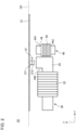
- Figs. 1 and 2 are diagrams illustrating a configuration of an actuator 10 according to a first example embodiment.
- Fig. 1 is a plan view of the actuator 10
- Fig. 2 is a side view of the actuator 10.
- Each drawing also illustrates an x-axis, a y-axis, and a z-axis as three axes that are orthogonal to one another.
- the x-axis is parallel to a first axis 201
- the y-axis is parallel to a second axis 202.
- Fig. 3 is a plan view illustrating a structural body 12 that includes a mirror 20, an outer side frame 50, and an inner side frame 60.
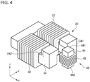
- Fig. 4 is a perspective view illustrating structures of a first electromagnet 30 and a second electromagnet 40.
- the actuator 10 includes the mirror 20, the first electromagnet 30, and the second electromagnet 40.
- a permanent magnet 21 is provided to the mirror 20.
- the mirror 20 can oscillate with respect to a reference plane 101, using the first axis 201 and the second axis 202 as oscillation axes.
- the first axis 201 and the second axis 202 are not parallel to each other.
- the first electromagnet 30 causes the mirror 20 to oscillate with respect to the first axis 201.
- the second electromagnet 40 causes the mirror 20 to oscillate with respect to the second axis 202. At least either (A) or (B) indicated below is established in the actuator 10.
- the mirror 20 has a reflecting surface 22, and the permanent magnet 21 is fixed to the center of a surface on the side opposite to the reflecting surface 22.
- a first pole 211 that is one pole of the permanent magnet 21 faces the mirror 20 side, and a second pole 212 that is the other pole of the permanent magnet 21 faces the side opposite to the mirror 20, that is, a side on which the first electromagnet 30 and the second electromagnet 40 are provided.
- the reference plane 101 is a plane including the reflecting surface 22 of the mirror 20 when the actuator 10 is in a state in which no current flows through coils on all the electromagnets provided to the actuator 10, that is, a reference state in which no force is exerted on the permanent magnet 21. Note that both Figs. 1 and 2 illustrate the reference state.
- the reference plane 101 is parallel to the xy-plane.
- the actuator 10 is a biaxial actuator and is capable of causing the mirror 20 to oscillate with respect to the first axis 201 and the second axis 202. Because of this configuration, direction of light reflected by the reflecting surface 22 of the mirror 20 can be two-dimensionally changed.
- the first axis 201 and the second axis 202 are substantially perpendicular or perpendicular to each other.
- a coil 32 is wound around at least a portion of a yoke 34. Current flowing through the coil 32 causes magnetic flux to be generated between an end portion 341 and an end portion 342. The magnetic flux acting on the permanent magnet 21 enables the mirror 20 to be caused to oscillate with respect to the first axis 201.
- a coil 42 is wound around at least a portion of a yoke 44. Current flowing through the coil 42 causes magnetic flux extending from a first end portion 441 and a second end portion 442 to be generated. The magnetic flux acting on the permanent magnet 21 enables the mirror 20 to be caused to oscillate with respect to the second axis 202.
- Figs. 5 and 6 are diagrams each illustrating comparative examples of an arrangement of electromagnets.
- two electromagnets for causing a mirror (not illustrated) to oscillate with respect to two axes are illustrated.
- an electromagnet 91 drives the mirror, using an axis 910 as an oscillation axis
- an electromagnet 92 drives the mirror, using an axis 920 as an oscillation axis.
- the electromagnet 91 is line-symmetric with respect to the axis 910 and the electromagnet 92 is line-symmetric with respect to the axis 920.
- Fig. 5 two electromagnets for causing a mirror (not illustrated) to oscillate with respect to two axes are illustrated.
- an electromagnet 91 drives the mirror, using an axis 910 as an oscillation axis
- an electromagnet 92 drives the mirror, using an axis 920 as an oscillation axis.
- the electromagnet 91 is line-symmetric with respect to the
- an electromagnet 93 drives the mirror, using an axis 930 as an oscillation axis
- an electromagnet 94 drives the mirror, using an axis 940 as an oscillation axis.
- the electromagnet 93 is line-symmetric with respect to the axis 930
- the electromagnet 94 is line-symmetric with respect to the axis 940.
- two end portions where magnetic flux is generated are provided with respect to each oscillation axis and are arranged in a symmetric manner. As a result, necessity for one electromagnet to cross over the other electromagnet occurs in order to avoid structural interference with each other. Such a structure causes the electromagnets to inevitably become larger in size as a whole.
- arranging a plurality of electromagnets in an asymmetric manner enables the actuator 10 to be prevented from becoming larger in size.
- each of the first electromagnet 30 and the second electromagnet 40 includes a coil and a yoke.
- the first electromagnet 30 includes the coil 32 and the yoke 34.
- the second electromagnet 40 includes the coil 42 and the yoke 44.
- the first electromagnet 30 is U-shaped or C-shaped, and the second electromagnet 40 is I-shaped.
- the yoke 44 of the second electromagnet 40 includes the first end portion 441 that is located on the reference plane 101 side and the second end portion 442 that is located on the side opposite to the reference plane 101 side with reference to the coil 42 of the second electromagnet 40 as viewed from a direction parallel to the reference plane 101. As viewed from the direction perpendicular to the reference plane 101, at least a portion of the first end portion 441 overlaps the second end portion 442. All of the end portion 341, the end portion 342, the first end portion 441, and the second end portion 442 are end portions where magnetic flux is generated.
- the above-described (A) is not established, and the above-described (B) is established.
- the electromagnets may have a configuration in which (B) is not established or may have a configuration in which both (A) and (B) are established.
- the first electromagnet 30 does not surround the second electromagnet 40. Specifically, as viewed from at least any direction parallel to the reference plane 101 (for example the y-axis direction), the first electromagnet 30 and the second electromagnet 40 do not overlap each other. In the present example embodiment, portions of the yoke 34 of the first electromagnet 30 around which the coil 32 is wound extend in parallel to the reference plane 101. As viewed from the direction perpendicular to the reference plane 101, the coil 32 is located on the side opposite to the second electromagnet 40 with reference to the second axis 202. In addition, the end portion 341 and the end portion 342 are closer to the mirror 20 than the coil 32 is.
- the yoke 44 of the second electromagnet 40 extends in the direction perpendicular to the reference plane 101, and only one of both ends of the yoke 44 faces the mirror 20.
- a cross section of a portion of the yoke 44 around which the coil 42 is wound has a square shape. The numbers of end portions where magnetic flux is generated which face the structural body 12 are different between the first electromagnet 30 and the second electromagnet 40.
- the actuator 10 further includes the outer side frame 50, torsion bars 52, the inner side frame 60, and torsion bars 62.
- the outer side frame 50 and the inner side frame 60 are connected via two torsion bars 52.
- the inner side frame 60 and the mirror 20 are connected via two torsion bars 62.
- the outer side frame 50, the torsion bars 52, the inner side frame 60, the torsion bars 62, and the mirror 20 are integrally formed by, for example, performing fine processing on a semiconductor wafer, and the actuator 10 is a MEMS actuator.
- the whole of the first electromagnet 30 and the second electromagnet 40 is located on the one surface side of the structural body 12 including the outer side frame 50, the torsion bars 52, the inner side frame 60, the torsion bars 62, and the mirror 20.
- the outer side frame 50 is fixed with respect to a housing (not illustrated) of the actuator 10.
- the inner side frame 60 can oscillate with respect to the outer side frame 50, using the first axis 201 as an oscillation axis.
- the two torsion bars 52 coincide with the first axis 201. That is, the two torsion bars 52 extend along and overlap the first axis 201, and the inner side frame 60 oscillates with respect to the outer side frame 50, accompanied by torsion of the torsion bars 52.
- the mirror 20 can oscillate with respect to the inner side frame 60, using the second axis 202 as an oscillation axis.
- the two torsion bars 62 coincide with the second axis 202.
- the two torsion bars 62 extend along and overlap the second axis 202, and the mirror 20 oscillates with respect to the inner side frame 60, accompanied by torsion of the torsion bars 62.
- no torsion occurs in the torsion bars 52 or the torsion bars 62, and one surfaces of the outer side frame 50, the inner side frame 60, and the mirror 20 are in the same plane as the reference plane 101.
- the magnetic flux may extend from not only surfaces of the end portion 341 and the end portion 342 that face each other (in the example in the present drawing, surfaces perpendicular to the y-axis) but also side surfaces (in the example in the present drawing, surfaces perpendicular to the x-axis) and upper surfaces (in the example in the present drawing, surfaces perpendicular to the z-axis) of the end portion 341 and the end portion 342.
- the magnetic flux described above acts on the permanent magnet 21 and thereby drives the mirror 20.
- the center of the first end portion 441 and the center of the mirror 20 do not overlap each other. That is, the first end portion 441 and the mirror 20 are shifted from each other.
- the center of the first end portion 441 is shifted from the center of the mirror 20 in a direction perpendicular to the second axis 202 (the x-axis direction).
- the center of the first end portion 441 is not shifted from the center of the mirror 20 in a direction parallel to the second axis 202 (the y-axis direction).
- the magnetic flux may extend from an upper surface of the first end portion 441 (in the example in the present drawing, a surface perpendicular to the z-axis), an undersurface of the second end portion 442 (in the example in the present drawing, a surface perpendicular to the z-axis), and side surfaces of the first end portion 441 and the second end portion 442 (in the example in the present drawing, surfaces perpendicular to the y-axis or the x-axis).
- the magnetic flux described above acts on the permanent magnet 21 and thereby drives the mirror 20.
- the second electromagnet 40 drives the mirror 20 in such a way that the mirror 20 oscillates at a resonant frequency.
- Driving force is likely to be smaller in the case of driving by pointing only one end portion where magnetic flux is generated to the permanent magnet 21 side like the case of the second electromagnet 40 than in the case of driving by pointing two end portions where magnetic flux is generated to the permanent magnet 21 like the case of the first electromagnet 30.
- driving the mirror 20 in such a way that the mirror 20 oscillates at a resonant frequency enables the mirror 20 to be sufficiently driven even with a small force.
- Fig. 7 is a diagram illustrating a variation of a cross-sectional shape of a yoke of the second electromagnet 40.
- a cross section of a portion of the yoke 44 around which the coil 42 is wound in the second electromagnet 40 has a rectangular shape.
- Fig. 8 is a diagram illustrating a variation of a winding method of the coil 42.
- the coils 42 is wound around the yoke 44 in a lap winding manner in the second electromagnet 40.
- At least either (A) or (B) described above is established.
- a degree of freedom in arrangement of two electromagnets in design increases, and the actuator 10 can be miniaturized.
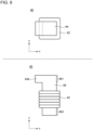
- Fig. 9 is a diagram illustrating a shape of a second electromagnet 40 according to a second example embodiment.
- An actuator 10 according to the present example embodiment is the same as the actuator 10 according to the first example embodiment except the shape of the second electromagnet 40, which will be described below.
- a plan view and a side view of the second electromagnet 40 are illustrated in the upper part and the lower part of the drawing, respectively.
- a projecting portion 444 that projects to the permanent magnet 21 side as viewed from a direction perpendicular to a reference plane 101 is formed on at least one of a first end portion 441 and a second end portion 442.
- the projecting portion 444 being formed causes an end portion, where magnetic flux is generated, of a yoke 44 and the permanent magnet 21 to come closer to each other and enables driving force exerted on a mirror 20 to be increased.
- a portion around which the coil 42 is wound becomes thick and it becomes necessary to set the central axis of the yoke 44 farther apart from the permanent magnet 21. Even in such a case, forming the projecting portion 444 enables magnetic flux to sufficiently act on the permanent magnet 21.
- the projecting portion 444 is formed only on the first end portion 441. Forming the projecting portion 444 on the first end portion 441 enables driving force to be increased more effectively. In addition, not forming the projecting portion 444 on the second end portion 442 enables miniaturization and weight reduction of the actuator 10 to be achieved more easily than in the case of forming the projecting portion 444 on the second end portion 442.
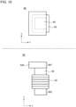
- Figs. 10 to 16 are diagrams each illustrating variations of the shape of the second electromagnet 40 according to the present example embodiment. The variations will be described below in order.
- a projecting portion 444 projects not only to the permanent magnet 21 side but also in a y-axis direction.
- a projecting portion 444 further projects to the side opposite to the permanent magnet 21 side. Enlarging the projecting portion 444 enables driving force to be further increased.
- a projecting portion 444 is formed only on the second end portion 442. Even such a configuration enables driving force exerted on the mirror 20 by the second electromagnet 40 to be increased.
- the shape of the projecting portion 444 on the second end portion 442 side is not limited to a specific shape and may be a shape like the shape in Fig. 10 or 11 .
- projecting portions 444 are formed on both the first end portion 441 and the second end portion 442. By employing such a configuration, it is possible to increase driving force more than in the case where a projecting portion 444 is formed on either the first end portion 441 or the second end portion 442.
- the projecting portion 444 on the first end portion 441 side and the projecting portion 444 on the second end portion 442 side have the same shape.
- the projecting portion 444 on the first end portion 441 side and the projecting portion 444 on the second end portion 442 side have different shapes.
- a projecting portion 444 that projects to the permanent magnet 21 side as viewed from the direction perpendicular to the reference plane 101 is formed on at least one of the first end portion 441 and the second end portion 442.
- Fig. 17 is a diagram illustrating a configuration of an actuator 10 according to a third example embodiment.
- the actuator 10 according to the present example embodiment is the same as the actuator 10 according to at least either the first example embodiment or the second example embodiment except that a first electromagnet 30 drives a mirror 20 in such a way that the mirror 20 oscillates at a resonant frequency.
- an inner side frame 60 can oscillate with respect to an outer side frame 50, using a second axis 202 as an oscillation axis.
- Two torsion bars 52 coincide with the second axis 202. That is, the two torsion bars 52 extend along and overlap the second axis 202, and the inner side frame 60 oscillates with respect to the outer side frame 50, accompanied by torsion of the torsion bars 52.
- the mirror 20 can oscillate with respect to the inner side frame 60, using a first axis 201 as an oscillation axis.
- Two torsion bars 62 coincide with the first axis 201. That is, the two torsion bars 62 extend along and overlap the first axis 201, and the mirror 20 oscillates with respect to the inner side frame 60, accompanied by torsion of the torsion bars 62.
- Fig. 18 is a diagram illustrating a structure of a first electromagnet 30 according to the present example embodiment.
- An actuator 10 according to the present example embodiment is the same as the actuator 10 according to at least one of the first to third example embodiments except a feature that will be described below.
- a permanent magnet 21 is illustrated by a dashed line.
- the first electromagnet 30 is composed of two electromagnets, namely an electromagnet 70 and an electromagnet 80.
- a yoke 34 of the first electromagnet 30 is separated into two portions.
- the first electromagnet 30 is line-symmetric with respect to a first axis 201 as a whole.
- the electromagnet 70 and the electromagnet 80 each extend in parallel to the first axis 201 as viewed from a direction perpendicular to a reference plane 101.
- the first electromagnet 30 does not overlap the first axis 201 as viewed from the direction perpendicular to the reference plane 101.
- the electromagnet 70 includes a coil 72 and a yoke 74
- the electromagnet 80 includes a coil 82 and a yoke 84.
- the coil 72 is wound around at least a portion of the yoke 74.
- the coil 82 is wound around at least a portion of the yoke 84.
- the first electromagnet 30 also functions in a similar manner to the first electromagnet 30 according to the first example embodiment. Specifically, an end portion 741 and an end portion 841 face each other and form a pair.
- the end portion 741 of the electromagnet 70 functions as the end portion 341 that was described in the first example embodiment
- the end portion 841 of the electromagnet 80 functions as the end portion 342 that was described in the first example embodiment.
- the yoke 34 of the first electromagnet 30 is separated into two portions.
- a degree of freedom in arrangement of two electromagnets in design further increases, and the actuator 10 can be further miniaturized.
- the actuator 10 may further include, in addition to the constituent elements illustrated in the drawings, a portion supporting each constituent element, wiring, a control unit, and the like.
- the shapes of the mirror 20, the first electromagnet 30, the second electromagnet 40, the structural body 12, and the like are not limited to examples in the present example embodiment.
Landscapes
- Physics & Mathematics (AREA)
- General Physics & Mathematics (AREA)
- Optics & Photonics (AREA)
- Electromagnetism (AREA)
- Mechanical Optical Scanning Systems (AREA)
- Mechanical Light Control Or Optical Switches (AREA)
- Micromachines (AREA)
- Reciprocating, Oscillating Or Vibrating Motors (AREA)
Abstract
Description
- The present invention relates to an actuator.
- In a measurement device or the like that performs measurement by scanning a predetermined area with light, a movable mirror is used to make an emission direction of light variable.
- Patent Document 1 describes an optical scanning device that causes a permanent magnet fixed to a mirror and an electromagnet to interact and thereby causes driving torque to be generated in the mirror.
- Patent Document 1:
Japanese Patent Application Publication No. 2009-69676 - Miniaturization of an actuator driving a mirror is important for miniaturization of the whole of a measurement device or the like including the actuator. On the other hand, there has been a problem in that, when a mirror is to be driven with respect to two axes, two electromagnets are required and an actuator becomes larger in size.
- A problem to be solved by the present invention includes miniaturizing an actuator that biaxially drives a mirror as one example.
- The invention described in claim 1 is an actuator including:
- a mirror on which a permanent magnet is provided and that can oscillate with respect to a reference plane, by using a first axis and a second axis not being parallel to the first axis as oscillation axes;
- a first electromagnet that causes the mirror to oscillate with respect to the first axis; and
- a second electromagnet that causes the mirror to oscillate with respect to the second axis, wherein
- at least either (A) the first electromagnet not being line-symmetric with respect to the first axis as viewed from a direction perpendicular to the reference plane or (B) the second electromagnet not being line-symmetric with respect to the second axis as viewed from a direction perpendicular to the reference plane is established.
-
-
Fig. 1 is a diagram illustrating a configuration of an actuator according to a first example embodiment. -
Fig. 2 is another diagram illustrating the configuration of the actuator according to the first example embodiment. -
Fig. 3 is a plan view illustrating a structural body that includes a mirror, an outer side frame, and an inner side frame. -
Fig. 4 is a perspective view illustrating structures of a first electromagnet and a second electromagnet. -
Fig. 5 is a diagram illustrating a comparative example of an arrangement of electromagnets. -
Fig. 6 is a diagram illustrating another comparative example of the arrangement of the electromagnets. -
Fig. 7 is a diagram illustrating a variation of a cross-sectional shape of a yoke of the second electromagnet. -
Fig. 8 is a diagram illustrating a variation of a winding method of a coil. -
Fig. 9 is a diagram illustrating a shape of a second electromagnet according to a second example embodiment. -
Fig. 10 is a diagram illustrating a variation of the shape of the second electromagnet according to the second example embodiment. -
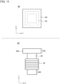
Fig. 11 is a diagram illustrating another variation of the shape of the second electromagnet according to the second example embodiment. -
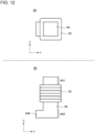
Fig. 12 is a diagram illustrating still another variation of the shape of the second electromagnet according to the second example embodiment. -
Fig. 13 is a diagram illustrating still another variation of the shape of the second electromagnet according to the second example embodiment. -
Fig. 14 is a diagram illustrating still another variation of the shape of the second electromagnet according to the second example embodiment. -
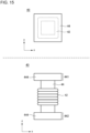
Fig. 15 is a diagram illustrating still another variation of the shape of the second electromagnet according to the second example embodiment. -
Fig. 16 is a diagram illustrating still another variation of the shape of the second electromagnet according to the second example embodiment. -
Fig. 17 is a diagram illustrating a configuration of an actuator according to a third example embodiment. -
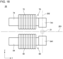
Fig. 18 is a diagram illustrating a structure of a first electromagnet according to a fourth example embodiment. - Hereinafter, example embodiments of the present invention will be described with reference to the drawings. Note that the same reference signs are assigned to the same constituent elements throughout the drawings, and description thereof is omitted appropriately.
-
Figs. 1 and2 are diagrams illustrating a configuration of anactuator 10 according to a first example embodiment.Fig. 1 is a plan view of theactuator 10, andFig. 2 is a side view of theactuator 10. Each drawing also illustrates an x-axis, a y-axis, and a z-axis as three axes that are orthogonal to one another. In the present example embodiment, the x-axis is parallel to afirst axis 201, and the y-axis is parallel to asecond axis 202. In addition,Fig. 3 is a plan view illustrating astructural body 12 that includes amirror 20, anouter side frame 50, and aninner side frame 60.Fig. 4 is a perspective view illustrating structures of afirst electromagnet 30 and asecond electromagnet 40. - The
actuator 10 according to the present example embodiment includes themirror 20, thefirst electromagnet 30, and thesecond electromagnet 40. Apermanent magnet 21 is provided to themirror 20. Themirror 20 can oscillate with respect to areference plane 101, using thefirst axis 201 and thesecond axis 202 as oscillation axes. Thefirst axis 201 and thesecond axis 202 are not parallel to each other. Thefirst electromagnet 30 causes themirror 20 to oscillate with respect to thefirst axis 201. Thesecond electromagnet 40 causes themirror 20 to oscillate with respect to thesecond axis 202. At least either (A) or (B) indicated below is established in theactuator 10. - (A) The
first electromagnet 30 is not line-symmetric with respect to thefirst axis 201 as viewed from a direction perpendicular to the reference plane 101 (z-axis direction). - (B) The
second electromagnet 40 is not line-symmetric with respect to thesecond axis 202 as viewed from the direction perpendicular to thereference plane 101. - A detailed description follows.
- The
mirror 20 has a reflectingsurface 22, and thepermanent magnet 21 is fixed to the center of a surface on the side opposite to the reflectingsurface 22. Afirst pole 211 that is one pole of thepermanent magnet 21 faces themirror 20 side, and asecond pole 212 that is the other pole of thepermanent magnet 21 faces the side opposite to themirror 20, that is, a side on which thefirst electromagnet 30 and thesecond electromagnet 40 are provided. Thereference plane 101 is a plane including the reflectingsurface 22 of themirror 20 when theactuator 10 is in a state in which no current flows through coils on all the electromagnets provided to theactuator 10, that is, a reference state in which no force is exerted on thepermanent magnet 21. Note that bothFigs. 1 and2 illustrate the reference state. Thereference plane 101 is parallel to the xy-plane. - The
actuator 10 is a biaxial actuator and is capable of causing themirror 20 to oscillate with respect to thefirst axis 201 and thesecond axis 202. Because of this configuration, direction of light reflected by thereflecting surface 22 of themirror 20 can be two-dimensionally changed. In the present example embodiment, thefirst axis 201 and thesecond axis 202 are substantially perpendicular or perpendicular to each other. - On the
first electromagnet 30, acoil 32 is wound around at least a portion of ayoke 34. Current flowing through thecoil 32 causes magnetic flux to be generated between anend portion 341 and anend portion 342. The magnetic flux acting on thepermanent magnet 21 enables themirror 20 to be caused to oscillate with respect to thefirst axis 201. In addition, on thesecond electromagnet 40, acoil 42 is wound around at least a portion of ayoke 44. Current flowing through thecoil 42 causes magnetic flux extending from afirst end portion 441 and asecond end portion 442 to be generated. The magnetic flux acting on thepermanent magnet 21 enables themirror 20 to be caused to oscillate with respect to thesecond axis 202. - As described above, at least either (A) or (B) described above is established in the
actuator 10. By arranging a plurality of electromagnets in an asymmetric manner as described above, miniaturization of theactuator 10 can be achieved. -
Figs. 5 and6 are diagrams each illustrating comparative examples of an arrangement of electromagnets. In each ofFigs. 5 and6 , two electromagnets for causing a mirror (not illustrated) to oscillate with respect to two axes are illustrated. InFig. 5 , anelectromagnet 91 drives the mirror, using anaxis 910 as an oscillation axis, and anelectromagnet 92 drives the mirror, using anaxis 920 as an oscillation axis. When the two electromagnets are viewed in the z-axis direction, theelectromagnet 91 is line-symmetric with respect to theaxis 910 and theelectromagnet 92 is line-symmetric with respect to theaxis 920. In addition, inFig. 6 , anelectromagnet 93 drives the mirror, using anaxis 930 as an oscillation axis, and anelectromagnet 94 drives the mirror, using anaxis 940 as an oscillation axis. When the two electromagnets are viewed in the z-axis direction, theelectromagnet 93 is line-symmetric with respect to theaxis 930 and theelectromagnet 94 is line-symmetric with respect to theaxis 940. In the examples, two end portions where magnetic flux is generated are provided with respect to each oscillation axis and are arranged in a symmetric manner. As a result, necessity for one electromagnet to cross over the other electromagnet occurs in order to avoid structural interference with each other. Such a structure causes the electromagnets to inevitably become larger in size as a whole. - In contrast, in the
actuator 10 according to the present example embodiment, arranging a plurality of electromagnets in an asymmetric manner enables theactuator 10 to be prevented from becoming larger in size. - With reference to
Figs. 1 ,2 , and4 , thefirst electromagnet 30 and thesecond electromagnet 40 will be further described. In theactuator 10 according to the present example embodiment, each of thefirst electromagnet 30 and thesecond electromagnet 40 includes a coil and a yoke. Specifically, thefirst electromagnet 30 includes thecoil 32 and theyoke 34. Thesecond electromagnet 40 includes thecoil 42 and theyoke 44. Thefirst electromagnet 30 is U-shaped or C-shaped, and thesecond electromagnet 40 is I-shaped. Specifically, both ends (theend portion 341 and the end portion 342) of theyoke 34 of thefirst electromagnet 30 face each other with at least a portion of thepermanent magnet 21 therebetween as viewed from the direction perpendicular to thereference plane 101. Theyoke 44 of thesecond electromagnet 40 includes thefirst end portion 441 that is located on thereference plane 101 side and thesecond end portion 442 that is located on the side opposite to thereference plane 101 side with reference to thecoil 42 of thesecond electromagnet 40 as viewed from a direction parallel to thereference plane 101. As viewed from the direction perpendicular to thereference plane 101, at least a portion of thefirst end portion 441 overlaps thesecond end portion 442. All of theend portion 341, theend portion 342, thefirst end portion 441, and thesecond end portion 442 are end portions where magnetic flux is generated. - In the example in
Fig. 1 , the above-described (A) is not established, and the above-described (B) is established. However, the electromagnets may have a configuration in which (B) is not established or may have a configuration in which both (A) and (B) are established. - In the present example embodiment, the
first electromagnet 30 does not surround thesecond electromagnet 40. Specifically, as viewed from at least any direction parallel to the reference plane 101 (for example the y-axis direction), thefirst electromagnet 30 and thesecond electromagnet 40 do not overlap each other. In the present example embodiment, portions of theyoke 34 of thefirst electromagnet 30 around which thecoil 32 is wound extend in parallel to thereference plane 101. As viewed from the direction perpendicular to thereference plane 101, thecoil 32 is located on the side opposite to thesecond electromagnet 40 with reference to thesecond axis 202. In addition, theend portion 341 and theend portion 342 are closer to themirror 20 than thecoil 32 is. Theyoke 44 of thesecond electromagnet 40 extends in the direction perpendicular to thereference plane 101, and only one of both ends of theyoke 44 faces themirror 20. In the example in the present drawing, a cross section of a portion of theyoke 44 around which thecoil 42 is wound has a square shape. The numbers of end portions where magnetic flux is generated which face thestructural body 12 are different between thefirst electromagnet 30 and thesecond electromagnet 40. - Next, with reference to
Figs. 1 and3 , thestructural body 12 including themirror 20, theouter side frame 50, and theinner side frame 60 will be described. Theactuator 10 further includes theouter side frame 50,torsion bars 52, theinner side frame 60, and torsion bars 62. Theouter side frame 50 and theinner side frame 60 are connected via two torsion bars 52. Theinner side frame 60 and themirror 20 are connected via two torsion bars 62. Theouter side frame 50, the torsion bars 52, theinner side frame 60, the torsion bars 62, and themirror 20 are integrally formed by, for example, performing fine processing on a semiconductor wafer, and theactuator 10 is a MEMS actuator. In the present example embodiment, the whole of thefirst electromagnet 30 and thesecond electromagnet 40 is located on the one surface side of thestructural body 12 including theouter side frame 50, the torsion bars 52, theinner side frame 60, the torsion bars 62, and themirror 20. - For example, the
outer side frame 50 is fixed with respect to a housing (not illustrated) of theactuator 10. Theinner side frame 60 can oscillate with respect to theouter side frame 50, using thefirst axis 201 as an oscillation axis. The twotorsion bars 52 coincide with thefirst axis 201. That is, the twotorsion bars 52 extend along and overlap thefirst axis 201, and theinner side frame 60 oscillates with respect to theouter side frame 50, accompanied by torsion of the torsion bars 52. In addition, themirror 20 can oscillate with respect to theinner side frame 60, using thesecond axis 202 as an oscillation axis. The twotorsion bars 62 coincide with thesecond axis 202. That is, the twotorsion bars 62 extend along and overlap thesecond axis 202, and themirror 20 oscillates with respect to theinner side frame 60, accompanied by torsion of the torsion bars 62. In the above-described reference state, no torsion occurs in the torsion bars 52 or the torsion bars 62, and one surfaces of theouter side frame 50, theinner side frame 60, and themirror 20 are in the same plane as thereference plane 101. - With reference to
Figs. 1 and2 , drive of theactuator 10 by thefirst electromagnet 30 will be described below. When current flows through thecoil 32 of thefirst electromagnet 30, magnetic flux is generated between theend portion 341 and theend portion 342. On this occasion, theend portion 341 and theend portion 342 have polarities different from each other. Then, the direction of themirror 20 changes in such a way that thepermanent magnet 21 points to, of theend portion 341 and theend portion 342, an end portion that has a different polarity from thesecond pole 212. Changing direction and magnitude of current flowed through thecoil 32 enables direction of the reflectingsurface 22 of themirror 20 to be controlled. Note that the magnetic flux may extend from not only surfaces of theend portion 341 and theend portion 342 that face each other (in the example in the present drawing, surfaces perpendicular to the y-axis) but also side surfaces (in the example in the present drawing, surfaces perpendicular to the x-axis) and upper surfaces (in the example in the present drawing, surfaces perpendicular to the z-axis) of theend portion 341 and theend portion 342. The magnetic flux described above acts on thepermanent magnet 21 and thereby drives themirror 20. - Drive of the
actuator 10 by thesecond electromagnet 40 will be described below. As viewed from the direction perpendicular to thereference plane 101, the center of thefirst end portion 441 and the center of themirror 20 do not overlap each other. That is, thefirst end portion 441 and themirror 20 are shifted from each other. In the example in the present drawing, specifically, the center of thefirst end portion 441 is shifted from the center of themirror 20 in a direction perpendicular to the second axis 202 (the x-axis direction). On the other hand, the center of thefirst end portion 441 is not shifted from the center of themirror 20 in a direction parallel to the second axis 202 (the y-axis direction). When current flows through thecoil 42 of thesecond electromagnet 40, magnetic flux extending from thefirst end portion 441 is generated. The magnetic flux from thefirst end portion 441 acting on thepermanent magnet 21 causes themirror 20 to oscillate with respect to thesecond axis 202. Specifically, when a polarity of thefirst end portion 441 is different from a polarity of thesecond pole 212, the direction of themirror 20 changes in such a way that thepermanent magnet 21 points to thefirst end portion 441 side. In contrast, when the polarity of thefirst end portion 441 is the same as the polarity of thesecond pole 212, the direction of themirror 20 changes in such a way that thepermanent magnet 21 points in a direction in which thepermanent magnet 21 separates from thefirst end portion 441. Changing the direction and magnitude of current flowed through thecoil 42 enables the direction of the reflectingsurface 22 of themirror 20 to be controlled. Note that the magnetic flux may extend from an upper surface of the first end portion 441 (in the example in the present drawing, a surface perpendicular to the z-axis), an undersurface of the second end portion 442 (in the example in the present drawing, a surface perpendicular to the z-axis), and side surfaces of thefirst end portion 441 and the second end portion 442 (in the example in the present drawing, surfaces perpendicular to the y-axis or the x-axis). The magnetic flux described above acts on thepermanent magnet 21 and thereby drives themirror 20. - Performing the above-described drive by the
first electromagnet 30 and thesecond electromagnet 40 at the same time enables the reflectingsurface 22 to be caused to face in a desirable direction. - In the present example embodiment, the
second electromagnet 40 drives themirror 20 in such a way that themirror 20 oscillates at a resonant frequency. Driving force is likely to be smaller in the case of driving by pointing only one end portion where magnetic flux is generated to thepermanent magnet 21 side like the case of thesecond electromagnet 40 than in the case of driving by pointing two end portions where magnetic flux is generated to thepermanent magnet 21 like the case of thefirst electromagnet 30. In contrast, driving themirror 20 in such a way that themirror 20 oscillates at a resonant frequency enables themirror 20 to be sufficiently driven even with a small force. -
Fig. 7 is a diagram illustrating a variation of a cross-sectional shape of a yoke of thesecond electromagnet 40. In the example of the present drawing, a cross section of a portion of theyoke 44 around which thecoil 42 is wound in thesecond electromagnet 40 has a rectangular shape. By employing such a configuration, it is possible to increase cross-sectional area of the yoke and increase magnetic force that thesecond electromagnet 40 generates. As a result, it is possible to sufficiently drive themirror 20 even when themirror 20 is driven by pointing only one end portion where magnetic flux is generated to thepermanent magnet 21 side. -
Fig. 8 is a diagram illustrating a variation of a winding method of thecoil 42. In the example of the present drawing, thecoils 42 is wound around theyoke 44 in a lap winding manner in thesecond electromagnet 40. By employing such a configuration, it is possible to increase magnetic force that thesecond electromagnet 40 generates. As a result, it is possible to sufficiently drive themirror 20 even when themirror 20 is driven by pointing only one end portion where magnetic flux is generated to thepermanent magnet 21 side. - According to the present example embodiment described above, at least either (A) or (B) described above is established. By employing such a configuration, a degree of freedom in arrangement of two electromagnets in design increases, and the
actuator 10 can be miniaturized. -
Fig. 9 is a diagram illustrating a shape of asecond electromagnet 40 according to a second example embodiment. Anactuator 10 according to the present example embodiment is the same as theactuator 10 according to the first example embodiment except the shape of thesecond electromagnet 40, which will be described below. In each ofFigs. 9 to 16 , which will be described below, a plan view and a side view of thesecond electromagnet 40 are illustrated in the upper part and the lower part of the drawing, respectively. - In the present example embodiment, a projecting
portion 444 that projects to thepermanent magnet 21 side as viewed from a direction perpendicular to areference plane 101 is formed on at least one of afirst end portion 441 and asecond end portion 442. The projectingportion 444 being formed causes an end portion, where magnetic flux is generated, of ayoke 44 and thepermanent magnet 21 to come closer to each other and enables driving force exerted on amirror 20 to be increased. In addition, when acoil 42 is wound in a lap winding manner, a portion around which thecoil 42 is wound becomes thick and it becomes necessary to set the central axis of theyoke 44 farther apart from thepermanent magnet 21. Even in such a case, forming the projectingportion 444 enables magnetic flux to sufficiently act on thepermanent magnet 21. - In the example in
Fig. 9 , the projectingportion 444 is formed only on thefirst end portion 441. Forming the projectingportion 444 on thefirst end portion 441 enables driving force to be increased more effectively. In addition, not forming the projectingportion 444 on thesecond end portion 442 enables miniaturization and weight reduction of theactuator 10 to be achieved more easily than in the case of forming the projectingportion 444 on thesecond end portion 442. -
Figs. 10 to 16 are diagrams each illustrating variations of the shape of thesecond electromagnet 40 according to the present example embodiment. The variations will be described below in order. - In an example in
Fig. 10 , a projectingportion 444 projects not only to thepermanent magnet 21 side but also in a y-axis direction. In addition, in an example inFig. 11 , a projectingportion 444 further projects to the side opposite to thepermanent magnet 21 side. Enlarging the projectingportion 444 enables driving force to be further increased. - In an example in
Fig. 12 , a projectingportion 444 is formed only on thesecond end portion 442. Even such a configuration enables driving force exerted on themirror 20 by thesecond electromagnet 40 to be increased. Note that the shape of the projectingportion 444 on thesecond end portion 442 side is not limited to a specific shape and may be a shape like the shape inFig. 10 or11 . - In examples in
Figs. 13 to 16 , projectingportions 444 are formed on both thefirst end portion 441 and thesecond end portion 442. By employing such a configuration, it is possible to increase driving force more than in the case where a projectingportion 444 is formed on either thefirst end portion 441 or thesecond end portion 442. In the examples inFigs. 13 to 15 , the projectingportion 444 on thefirst end portion 441 side and the projectingportion 444 on thesecond end portion 442 side have the same shape. In the example inFig. 16 , the projectingportion 444 on thefirst end portion 441 side and the projectingportion 444 on thesecond end portion 442 side have different shapes. - According to the present example embodiment described above, effects and advantages similar to those in the first example embodiment can be achieved. In addition, a projecting
portion 444 that projects to thepermanent magnet 21 side as viewed from the direction perpendicular to thereference plane 101 is formed on at least one of thefirst end portion 441 and thesecond end portion 442. By employing such a configuration, it is possible to cause magnetic flux of thesecond electromagnet 40 to act on thepermanent magnet 21 more strongly and increase driving force exerted on themirror 20. -
Fig. 17 is a diagram illustrating a configuration of anactuator 10 according to a third example embodiment. Theactuator 10 according to the present example embodiment is the same as theactuator 10 according to at least either the first example embodiment or the second example embodiment except that afirst electromagnet 30 drives amirror 20 in such a way that themirror 20 oscillates at a resonant frequency. - In the present example embodiment, an
inner side frame 60 can oscillate with respect to anouter side frame 50, using asecond axis 202 as an oscillation axis. Twotorsion bars 52 coincide with thesecond axis 202. That is, the twotorsion bars 52 extend along and overlap thesecond axis 202, and theinner side frame 60 oscillates with respect to theouter side frame 50, accompanied by torsion of the torsion bars 52. In addition, themirror 20 can oscillate with respect to theinner side frame 60, using afirst axis 201 as an oscillation axis. Twotorsion bars 62 coincide with thefirst axis 201. That is, the twotorsion bars 62 extend along and overlap thefirst axis 201, and themirror 20 oscillates with respect to theinner side frame 60, accompanied by torsion of the torsion bars 62. - According to the present example embodiment described above, effects and advantages similar to those in the first example embodiment can be achieved.
-
Fig. 18 is a diagram illustrating a structure of afirst electromagnet 30 according to the present example embodiment. Anactuator 10 according to the present example embodiment is the same as theactuator 10 according to at least one of the first to third example embodiments except a feature that will be described below. In the present drawing, apermanent magnet 21 is illustrated by a dashed line. - In the present example embodiment, the
first electromagnet 30 is composed of two electromagnets, namely anelectromagnet 70 and anelectromagnet 80. In other words, ayoke 34 of thefirst electromagnet 30 is separated into two portions. Thefirst electromagnet 30 is line-symmetric with respect to afirst axis 201 as a whole. Theelectromagnet 70 and theelectromagnet 80 each extend in parallel to thefirst axis 201 as viewed from a direction perpendicular to areference plane 101. Thefirst electromagnet 30 does not overlap thefirst axis 201 as viewed from the direction perpendicular to thereference plane 101. - The
electromagnet 70 includes acoil 72 and ayoke 74, and theelectromagnet 80 includes acoil 82 and ayoke 84. Thecoil 72 is wound around at least a portion of theyoke 74. Thecoil 82 is wound around at least a portion of theyoke 84. In the configuration according to the present example embodiment, thefirst electromagnet 30 also functions in a similar manner to thefirst electromagnet 30 according to the first example embodiment. Specifically, anend portion 741 and anend portion 841 face each other and form a pair. Theend portion 741 of theelectromagnet 70 functions as theend portion 341 that was described in the first example embodiment, and theend portion 841 of theelectromagnet 80 functions as theend portion 342 that was described in the first example embodiment. - According to the present example embodiment described above, effects and advantages similar to those in the first example embodiment can be achieved. In addition, the
yoke 34 of thefirst electromagnet 30 is separated into two portions. By employing such a configuration, a degree of freedom in arrangement of two electromagnets in design further increases, and theactuator 10 can be further miniaturized. - Although the example embodiments have been described above with reference to the drawings, these are examples of the present invention, and various configurations other than the above can be adopted. For example, the
actuator 10 may further include, in addition to the constituent elements illustrated in the drawings, a portion supporting each constituent element, wiring, a control unit, and the like. In addition, the shapes of themirror 20, thefirst electromagnet 30, thesecond electromagnet 40, thestructural body 12, and the like are not limited to examples in the present example embodiment. -
- 10
- Actuator
- 12
- Structural body
- 20
- Mirror
- 21
- Permanent magnet
- 22
- Reflecting surface
- 30
- First electromagnet
- 32
- Coil
- 34
- Yoke
- 40
- Second electromagnet
- 42
- Coil
- 44
- Yoke
- 50
- Outer side frame
- 52
- Torsion bar
- 60
- Inner side frame
- 62
- Torsion bar
- 70
- Electromagnet
- 72
- Coil
- 74
- Yoke
- 80
- Electromagnet
- 82
- Coil
- 84
- Yoke
- 101
- Reference plane
- 201
- First axis
- 202
- Second axis
- 211
- First pole
- 212
- Second pole
- 341
- End portion
- 342
- End portion
- 441
- First end portion
- 442
- Second end portion
- 444
- Projecting portion
Claims (7)
- An actuator comprising:a mirror on which a permanent magnet is provided and that can oscillate with respect to a reference plane, by using a first axis and a second axis not being parallel to the first axis as oscillation axes;a first electromagnet that causes the mirror to oscillate with respect to the first axis; anda second electromagnet that causes the mirror to oscillate with respect to the second axis, whereinat least either (A) the first electromagnet not being line-symmetric with respect to the first axis as viewed from a direction perpendicular to the reference plane or (B) the second electromagnet not being line-symmetric with respect to the second axis as viewed from a direction perpendicular to the reference plane is established.
- The actuator according to claim 1, whereineach of the first electromagnet and the second electromagnet comprises a coil and a yoke,both ends of the yoke of the first electromagnet face each other with at least a portion of the permanent magnet therebetween as viewed from a direction perpendicular to the reference plane, andthe yoke of the second electromagnet includes a first end portion being located on the reference plane side and a second end portion being located on a side opposite to the reference plane side with reference to the coil of the second electromagnet as viewed from a direction parallel to the reference plane.
- The actuator according to claim 2, wherein
the second electromagnet drives the mirror in such a way that the mirror oscillates at a resonant frequency. - The actuator according to claim 2 or 3, wherein,
as viewed from a direction perpendicular to the reference plane, a center of the first end portion and a center of the mirror do not overlap each other. - The actuator according to any one of claims 2 to 4, wherein
a projecting portion that projects to the permanent magnet side as viewed from a direction perpendicular to the reference plane is provided on at least one of the first end portion and the second end portion. - The actuator according to any one of claims 2 to 5, wherein
a cross section of a portion of the yoke around which the coil is wound in the second electromagnet has a rectangular shape. - The actuator according to any one of claims 2 to 6, wherein
the coil is wound in a lap winding manner in the second electromagnet.
Applications Claiming Priority (1)
| Application Number | Priority Date | Filing Date | Title |
|---|---|---|---|
| PCT/JP2021/007501 WO2022180822A1 (en) | 2021-02-26 | 2021-02-26 | Actuator |
Publications (2)
| Publication Number | Publication Date |
|---|---|
| EP4300795A1 true EP4300795A1 (en) | 2024-01-03 |
| EP4300795A4 EP4300795A4 (en) | 2025-01-29 |
Family
ID=83049023
Family Applications (1)
| Application Number | Title | Priority Date | Filing Date |
|---|---|---|---|
| EP21927922.1A Pending EP4300795A4 (en) | 2021-02-26 | 2021-02-26 | ACTUATOR |
Country Status (4)
| Country | Link |
|---|---|
| US (1) | US12645068B2 (en) |
| EP (1) | EP4300795A4 (en) |
| JP (3) | JP7516651B2 (en) |
| WO (1) | WO2022180822A1 (en) |
Family Cites Families (12)
| Publication number | Priority date | Publication date | Assignee | Title |
|---|---|---|---|---|
| JP2000235152A (en) | 1999-02-12 | 2000-08-29 | Victor Co Of Japan Ltd | Optical deflector |
| DE19941363B4 (en) * | 1999-08-31 | 2006-06-08 | Fraunhofer-Gesellschaft zur Förderung der angewandten Forschung e.V. | Process for the preparation of a microactuator component |
| JP4380233B2 (en) | 2002-10-18 | 2009-12-09 | 日本ビクター株式会社 | Optical deflector |
| US7598688B2 (en) * | 2006-06-22 | 2009-10-06 | Orbotech Ltd | Tilting device |
| JP2009069676A (en) | 2007-09-14 | 2009-04-02 | Ricoh Co Ltd | Optical scanning device |
| KR20100063997A (en) | 2008-12-04 | 2010-06-14 | 삼성전자주식회사 | Laser scanning unit and method of detecting scanning sync signal |
| JP5720673B2 (en) | 2010-03-24 | 2015-05-20 | 日本電気株式会社 | Magnetic force type driving device, optical scanning device, and image display device |
| WO2013168264A1 (en) | 2012-05-10 | 2013-11-14 | パイオニア株式会社 | Drive device |
| WO2014192123A1 (en) | 2013-05-30 | 2014-12-04 | パイオニア株式会社 | Steel body structure |
| US9784838B1 (en) * | 2014-11-26 | 2017-10-10 | Apple Inc. | Compact scanner with gimbaled optics |
| US20180331605A1 (en) * | 2015-11-17 | 2018-11-15 | Mitsubishi Electric Corporation | Coil forming device and coil forming method |
| EP3764147B1 (en) * | 2018-03-09 | 2023-03-22 | Pioneer Corporation | Reflector with actuator, optical scanner, and mirror actuator |
-
2021
- 2021-02-26 EP EP21927922.1A patent/EP4300795A4/en active Pending
- 2021-02-26 US US18/277,876 patent/US12645068B2/en active Active
- 2021-02-26 WO PCT/JP2021/007501 patent/WO2022180822A1/en not_active Ceased
- 2021-02-26 JP JP2023501983A patent/JP7516651B2/en active Active
-
2024
- 2024-07-03 JP JP2024107436A patent/JP2024120997A/en active Pending
-
2025
- 2025-10-24 JP JP2025179359A patent/JP2026012221A/en active Pending
Also Published As
| Publication number | Publication date |
|---|---|
| US20240126068A1 (en) | 2024-04-18 |
| JP2026012221A (en) | 2026-01-23 |
| WO2022180822A1 (en) | 2022-09-01 |
| EP4300795A4 (en) | 2025-01-29 |
| JP7516651B2 (en) | 2024-07-16 |
| US12645068B2 (en) | 2026-06-02 |
| JP2024120997A (en) | 2024-09-05 |
| JPWO2022180822A1 (en) | 2022-09-01 |
Similar Documents
| Publication | Publication Date | Title |
|---|---|---|
| US20070268099A1 (en) | Actuator and two-dimensional scanner | |
| JP2005173411A (en) | Optical deflector | |
| US20090109512A1 (en) | Mems scanner having actuator separated from mirror | |
| US20020113675A1 (en) | Movable-body apparatus, optical deflector, and method of fabricating the same | |
| EP3006395B1 (en) | Drive device | |
| WO2012070610A1 (en) | Optical scanning device | |
| WO2013168264A1 (en) | Drive device | |
| WO2013168266A1 (en) | Drive device | |
| WO2012172652A1 (en) | Drive device | |
| EP3719559B1 (en) | Actuator device | |
| WO2019150109A1 (en) | Vibrational energy harvesters with reduced wear | |
| JP2005169553A (en) | Micro actuator | |
| US20240126068A1 (en) | Actuator | |
| KR101897234B1 (en) | A micro scanner | |
| JP2021033087A (en) | Mirror scanner | |
| JP6424477B2 (en) | MEMS device | |
| JP4286553B2 (en) | Planar type actuator | |
| KR102941778B1 (en) | Reflector scanner | |
| JP7546752B2 (en) | Actuator | |
| WO2013168273A1 (en) | Drive device | |
| JP2013101199A (en) | Mirror device, optical scanner and image formation apparatus | |
| US20200271919A1 (en) | Actuator | |
| WO2013168271A1 (en) | Drive device | |
| JP5624213B2 (en) | Drive device | |
| WO2022180736A1 (en) | Actuator |
Legal Events
| Date | Code | Title | Description |
|---|---|---|---|
| STAA | Information on the status of an ep patent application or granted ep patent |
Free format text: STATUS: THE INTERNATIONAL PUBLICATION HAS BEEN MADE |
|
| PUAI | Public reference made under article 153(3) epc to a published international application that has entered the european phase |
Free format text: ORIGINAL CODE: 0009012 |
|
| STAA | Information on the status of an ep patent application or granted ep patent |
Free format text: STATUS: REQUEST FOR EXAMINATION WAS MADE |
|
| 17P | Request for examination filed |
Effective date: 20230926 |
|
| AK | Designated contracting states |
Kind code of ref document: A1 Designated state(s): AL AT BE BG CH CY CZ DE DK EE ES FI FR GB GR HR HU IE IS IT LI LT LU LV MC MK MT NL NO PL PT RO RS SE SI SK SM TR |
|
| DAV | Request for validation of the european patent (deleted) | ||
| DAX | Request for extension of the european patent (deleted) | ||
| REG | Reference to a national code |
Ref country code: DE Ref legal event code: R079 Free format text: PREVIOUS MAIN CLASS: H02K0015120000 Ipc: G02B0026080000 |
|
| A4 | Supplementary search report drawn up and despatched |
Effective date: 20250108 |
|
| RIC1 | Information provided on ipc code assigned before grant |
Ipc: G02B 26/08 20060101AFI20241223BHEP |