EP4300740A1 - Starre unterwasserstromkabelverbindung - Google Patents
Starre unterwasserstromkabelverbindung Download PDFInfo
- Publication number
- EP4300740A1 EP4300740A1 EP22182293.5A EP22182293A EP4300740A1 EP 4300740 A1 EP4300740 A1 EP 4300740A1 EP 22182293 A EP22182293 A EP 22182293A EP 4300740 A1 EP4300740 A1 EP 4300740A1
- Authority
- EP
- European Patent Office
- Prior art keywords
- power cable
- submarine power
- submarine
- core
- static
- Prior art date
- Legal status (The legal status is an assumption and is not a legal conclusion. Google has not performed a legal analysis and makes no representation as to the accuracy of the status listed.)
- Pending
Links
- 230000003068 static effect Effects 0.000 claims description 51
- 239000013307 optical fiber Substances 0.000 claims description 28
- 238000009413 insulation Methods 0.000 claims description 23
- 239000004020 conductor Substances 0.000 claims description 16
- 239000000835 fiber Substances 0.000 claims description 10
- 230000001419 dependent effect Effects 0.000 claims 1
- 239000004743 Polypropylene Substances 0.000 description 6
- 238000005452 bending Methods 0.000 description 6
- 229920001155 polypropylene Polymers 0.000 description 6
- -1 polypropylene Polymers 0.000 description 5
- 229910000831 Steel Inorganic materials 0.000 description 4
- 239000010935 stainless steel Substances 0.000 description 4
- 229910001220 stainless steel Inorganic materials 0.000 description 4
- 239000010959 steel Substances 0.000 description 4
- 229920002943 EPDM rubber Polymers 0.000 description 3
- 229920000181 Ethylene propylene rubber Polymers 0.000 description 3
- 229920003020 cross-linked polyethylene Polymers 0.000 description 3
- 239000004703 cross-linked polyethylene Substances 0.000 description 3
- 239000003351 stiffener Substances 0.000 description 3
- 229920002725 thermoplastic elastomer Polymers 0.000 description 3
- XLYOFNOQVPJJNP-UHFFFAOYSA-N water Substances O XLYOFNOQVPJJNP-UHFFFAOYSA-N 0.000 description 3
- 238000003466 welding Methods 0.000 description 3
- 239000000945 filler Substances 0.000 description 2
- 238000009434 installation Methods 0.000 description 2
- 238000004519 manufacturing process Methods 0.000 description 2
- 239000002184 metal Substances 0.000 description 2
- 239000007769 metal material Substances 0.000 description 2
- 229920000642 polymer Polymers 0.000 description 2
- 229920005604 random copolymer Polymers 0.000 description 2
- 229910001335 Galvanized steel Inorganic materials 0.000 description 1
- 238000004873 anchoring Methods 0.000 description 1
- 239000008397 galvanized steel Substances 0.000 description 1
- 239000000463 material Substances 0.000 description 1
- 230000035515 penetration Effects 0.000 description 1
- 238000007789 sealing Methods 0.000 description 1
Images


Classifications
-
- H—ELECTRICITY
- H02—GENERATION; CONVERSION OR DISTRIBUTION OF ELECTRIC POWER
- H02G—INSTALLATION OF ELECTRIC CABLES OR LINES, OR OF COMBINED OPTICAL AND ELECTRIC CABLES OR LINES
- H02G15/00—Cable fittings
- H02G15/08—Cable junctions
-
- H—ELECTRICITY
- H02—GENERATION; CONVERSION OR DISTRIBUTION OF ELECTRIC POWER
- H02G—INSTALLATION OF ELECTRIC CABLES OR LINES, OR OF COMBINED OPTICAL AND ELECTRIC CABLES OR LINES
- H02G15/00—Cable fittings
- H02G15/08—Cable junctions
- H02G15/10—Cable junctions protected by boxes, e.g. by distribution, connection or junction boxes
-
- H—ELECTRICITY
- H02—GENERATION; CONVERSION OR DISTRIBUTION OF ELECTRIC POWER
- H02G—INSTALLATION OF ELECTRIC CABLES OR LINES, OR OF COMBINED OPTICAL AND ELECTRIC CABLES OR LINES
- H02G9/00—Installations of electric cables or lines in or on the ground or water
- H02G9/02—Installations of electric cables or lines in or on the ground or water laid directly in or on the ground, river-bed or sea-bottom; Coverings therefor, e.g. tile
-
- G—PHYSICS
- G02—OPTICS
- G02B—OPTICAL ELEMENTS, SYSTEMS OR APPARATUS
- G02B6/00—Light guides; Structural details of arrangements comprising light guides and other optical elements, e.g. couplings
- G02B6/44—Mechanical structures for providing tensile strength and external protection for fibres, e.g. optical transmission cables
- G02B6/4401—Optical cables
- G02B6/4415—Cables for special applications
- G02B6/4427—Pressure resistant cables, e.g. undersea cables
-
- H—ELECTRICITY
- H01—ELECTRIC ELEMENTS
- H01B—CABLES; CONDUCTORS; INSULATORS; SELECTION OF MATERIALS FOR THEIR CONDUCTIVE, INSULATING OR DIELECTRIC PROPERTIES
- H01B11/00—Communication cables or conductors
- H01B11/22—Cables including at least one electrical conductor together with optical fibres
-
- H—ELECTRICITY
- H01—ELECTRIC ELEMENTS
- H01B—CABLES; CONDUCTORS; INSULATORS; SELECTION OF MATERIALS FOR THEIR CONDUCTIVE, INSULATING OR DIELECTRIC PROPERTIES
- H01B17/00—Insulators or insulating bodies characterised by their form
- H01B17/56—Insulating bodies
- H01B17/58—Tubes, sleeves, beads, or bobbins through which the conductor passes
-
- H—ELECTRICITY
- H01—ELECTRIC ELEMENTS
- H01B—CABLES; CONDUCTORS; INSULATORS; SELECTION OF MATERIALS FOR THEIR CONDUCTIVE, INSULATING OR DIELECTRIC PROPERTIES
- H01B7/00—Insulated conductors or cables characterised by their form
- H01B7/02—Disposition of insulation
- H01B7/0208—Cables with several layers of insulating material
- H01B7/0225—Three or more layers
-
- H—ELECTRICITY
- H01—ELECTRIC ELEMENTS
- H01B—CABLES; CONDUCTORS; INSULATORS; SELECTION OF MATERIALS FOR THEIR CONDUCTIVE, INSULATING OR DIELECTRIC PROPERTIES
- H01B7/00—Insulated conductors or cables characterised by their form
- H01B7/16—Rigid-tube cables
-
- H—ELECTRICITY
- H01—ELECTRIC ELEMENTS
- H01B—CABLES; CONDUCTORS; INSULATORS; SELECTION OF MATERIALS FOR THEIR CONDUCTIVE, INSULATING OR DIELECTRIC PROPERTIES
- H01B7/00—Insulated conductors or cables characterised by their form
- H01B7/17—Protection against damage caused by external factors, e.g. sheaths or armouring
- H01B7/28—Protection against damage caused by moisture, corrosion, chemical attack or weather
- H01B7/282—Preventing penetration of fluid, e.g. water or humidity, into conductor or cable
- H01B7/2825—Preventing penetration of fluid, e.g. water or humidity, into conductor or cable using a water impermeable sheath
-
- H—ELECTRICITY
- H01—ELECTRIC ELEMENTS
- H01B—CABLES; CONDUCTORS; INSULATORS; SELECTION OF MATERIALS FOR THEIR CONDUCTIVE, INSULATING OR DIELECTRIC PROPERTIES
- H01B9/00—Power cables
- H01B9/005—Power cables including optical transmission elements
-
- H—ELECTRICITY
- H01—ELECTRIC ELEMENTS
- H01B—CABLES; CONDUCTORS; INSULATORS; SELECTION OF MATERIALS FOR THEIR CONDUCTIVE, INSULATING OR DIELECTRIC PROPERTIES
- H01B9/00—Power cables
- H01B9/006—Constructional features relating to the conductors
-
- H—ELECTRICITY
- H02—GENERATION; CONVERSION OR DISTRIBUTION OF ELECTRIC POWER
- H02G—INSTALLATION OF ELECTRIC CABLES OR LINES, OR OF COMBINED OPTICAL AND ELECTRIC CABLES OR LINES
- H02G15/00—Cable fittings
- H02G15/007—Devices for relieving mechanical stress
-
- H—ELECTRICITY
- H02—GENERATION; CONVERSION OR DISTRIBUTION OF ELECTRIC POWER
- H02G—INSTALLATION OF ELECTRIC CABLES OR LINES, OR OF COMBINED OPTICAL AND ELECTRIC CABLES OR LINES
- H02G15/00—Cable fittings
- H02G15/013—Sealing means for cable inlets
-
- H—ELECTRICITY
- H02—GENERATION; CONVERSION OR DISTRIBUTION OF ELECTRIC POWER
- H02G—INSTALLATION OF ELECTRIC CABLES OR LINES, OR OF COMBINED OPTICAL AND ELECTRIC CABLES OR LINES
- H02G9/00—Installations of electric cables or lines in or on the ground or water
- H02G9/12—Installations of electric cables or lines in or on the ground or water supported on or from floats, e.g. in water
-
- H—ELECTRICITY
- H01—ELECTRIC ELEMENTS
- H01B—CABLES; CONDUCTORS; INSULATORS; SELECTION OF MATERIALS FOR THEIR CONDUCTIVE, INSULATING OR DIELECTRIC PROPERTIES
- H01B7/00—Insulated conductors or cables characterised by their form
- H01B7/04—Flexible cables, conductors, or cords, e.g. trailing cables
- H01B7/045—Flexible cables, conductors, or cords, e.g. trailing cables attached to marine objects, e.g. buoys, diving equipment, aquatic probes, marine towline
-
- H—ELECTRICITY
- H01—ELECTRIC ELEMENTS
- H01B—CABLES; CONDUCTORS; INSULATORS; SELECTION OF MATERIALS FOR THEIR CONDUCTIVE, INSULATING OR DIELECTRIC PROPERTIES
- H01B7/00—Insulated conductors or cables characterised by their form
- H01B7/12—Floating cables
-
- H—ELECTRICITY
- H01—ELECTRIC ELEMENTS
- H01B—CABLES; CONDUCTORS; INSULATORS; SELECTION OF MATERIALS FOR THEIR CONDUCTIVE, INSULATING OR DIELECTRIC PROPERTIES
- H01B7/00—Insulated conductors or cables characterised by their form
- H01B7/14—Submarine cables
-
- H—ELECTRICITY
- H02—GENERATION; CONVERSION OR DISTRIBUTION OF ELECTRIC POWER
- H02G—INSTALLATION OF ELECTRIC CABLES OR LINES, OR OF COMBINED OPTICAL AND ELECTRIC CABLES OR LINES
- H02G1/00—Methods or apparatus specially adapted for installing, maintaining, repairing or dismantling electric cables or lines
- H02G1/06—Methods or apparatus specially adapted for installing, maintaining, repairing or dismantling electric cables or lines for laying cables, e.g. laying apparatus on vehicle
- H02G1/10—Methods or apparatus specially adapted for installing, maintaining, repairing or dismantling electric cables or lines for laying cables, e.g. laying apparatus on vehicle in or under water
-
- H—ELECTRICITY
- H02—GENERATION; CONVERSION OR DISTRIBUTION OF ELECTRIC POWER
- H02G—INSTALLATION OF ELECTRIC CABLES OR LINES, OR OF COMBINED OPTICAL AND ELECTRIC CABLES OR LINES
- H02G15/00—Cable fittings
- H02G15/02—Cable terminations
- H02G15/04—Cable-end sealings
- H02G15/043—Cable-end sealings with end caps, e.g. sleeve closed at one end
- H02G15/046—Cable-end sealings with end caps, e.g. sleeve closed at one end with bores or protruding portions allowing passage of cable conductors
-
- H—ELECTRICITY
- H02—GENERATION; CONVERSION OR DISTRIBUTION OF ELECTRIC POWER
- H02G—INSTALLATION OF ELECTRIC CABLES OR LINES, OR OF COMBINED OPTICAL AND ELECTRIC CABLES OR LINES
- H02G15/00—Cable fittings
- H02G15/02—Cable terminations
- H02G15/06—Cable terminating boxes, frames or other structures
-
- H—ELECTRICITY
- H02—GENERATION; CONVERSION OR DISTRIBUTION OF ELECTRIC POWER
- H02G—INSTALLATION OF ELECTRIC CABLES OR LINES, OR OF COMBINED OPTICAL AND ELECTRIC CABLES OR LINES
- H02G15/00—Cable fittings
- H02G15/08—Cable junctions
- H02G15/10—Cable junctions protected by boxes, e.g. by distribution, connection or junction boxes
- H02G15/113—Boxes split longitudinally in main cable direction
-
- H—ELECTRICITY
- H02—GENERATION; CONVERSION OR DISTRIBUTION OF ELECTRIC POWER
- H02G—INSTALLATION OF ELECTRIC CABLES OR LINES, OR OF COMBINED OPTICAL AND ELECTRIC CABLES OR LINES
- H02G15/00—Cable fittings
- H02G15/08—Cable junctions
- H02G15/10—Cable junctions protected by boxes, e.g. by distribution, connection or junction boxes
- H02G15/12—Cable junctions protected by boxes, e.g. by distribution, connection or junction boxes for incorporating transformers, loading coils or amplifiers
- H02G15/14—Cable junctions protected by boxes, e.g. by distribution, connection or junction boxes for incorporating transformers, loading coils or amplifiers specially adapted for submarine cables
Definitions
- the present disclosure generally relates to submarine power cable systems.
- Dynamic submarine power cables are designed to withstand stress created by wave motion.
- the dynamic submarine power cable extends from the floating offshore structure to the seabed where it may be jointed with a static submarine power cable that is laid on the seabed.
- the dynamic submarine power cables are generally AC power cables. There is however an increased interest in dynamic DC submarine power cables.
- a dynamic DC submarine cable system suspended from an offshore structure to the seabed would have to include two dynamic DC submarine power cables, one for each electric pole. This requires two sets of buoyancy units, anchoring, bend stiffeners, etc. - one for each power cable. Two dynamic DC submarine power cables furthermore take up a larger water column than a single dynamic AC submarine cable.
- a general object of the present disclosure is to provide a rigid submarine power cable joint which solves or at least mitigates problems of the prior art.
- a rigid submarine power cable joint comprising: an outer casing having a first axial end face and a second axial end face at an opposite axial end of the outer casing relative to the first axial end face, wherein the first axial end face comprises a single opening configured to receive a multi-core dynamic submarine power cable, and wherein the second axial end face comprises two openings, each configured to receive a respective single core submarine power cable.
- a jointing between a multi-core dynamic submarine power cable and two single core submarine power cables may thus be achieved.
- the single opening may have a circular cross-sectional shape.
- Each of the two openings may have a circular cross-sectional shape.
- the single opening is a through-opening.
- the two openings are through-openings.
- the single opening may be the only opening configured to receive a multi-core dynamic submarine power cable in the first axial end face. There is thus only one opening, i.e., the single opening, provided in the first axial end face, configured to receive a multi-core dynamic submarine power cable.
- the two openings may be the only openings configured to receive a respective single core submarine power cable in the second axial end face. There is thus only two opening, i.e., the two opening, provided in the second axial end face, configured to receive a respective single core submarine power cable.
- the first axial end face comprises a multi-core dynamic submarine power cable armour attachment structure arranged around the single opening and configured for attaching armour wires of the multi-core dynamic submarine power cable.
- the multi-core dynamic submarine power cable armour attachment structure may for example be a weld sleeve for welding the armour wires of the multi-core dynamic submarine power cable to the weld sleeve.
- the armour wires of the multi-core dynamic submarine power cables can thus be welded to the outer casing as they are terminated.
- the multi-core dynamic submarine power cable armour attachment structure may be a clamping member such as a clamping flange, for clamping the armour wires of the multi-core dynamic submarine power cable to the outer casing.
- the second axial end face comprises two single core submarine power cable armour attachment structures, each single core submarine power cable armour attachment structure being arranged around a respective one of the two openings, wherein each single core submarine power cable armour attachment structure is configured for attaching armour wires of a respective one of the single core submarine power cables.
- the two single core submarine power cable armour attachment structures may for example be weld sleeves for welding the armour wires of the single core submarine power cables to a respective weld sleeve.
- the armour wires of the singe core submarine power cables can thus be welded to the outer casing as they are terminated.
- each of the two single core submarine power cable armour attachment structures may be a clamping member such as a clamping flange, for clamping the armour wires of the two single core submarine power cables to the outer casing.
- the second axial end face comprises a third opening configured to receive an armoured submarine optical fibre cable, wherein the second axial end face comprises a submarine optical fibre armour attachment structure arranged around the third opening and configured for attachment of armour wires of the armoured submarine optical fibre cable.
- the submarine optical fibre armour attachment structure may for example be a weld sleeve for welding the armour wires of the armoured submarine optical fibre cable to the weld sleeve.
- the armour wires of the armoured submarine optical fibre cable can thus be welded to the outer casing as they are terminated.
- submarine optical fibre armour attachment structure may be a clamping member such as a clamping flange, for clamping the armour wires of the armoured submarine optical fibre cable to the outer casing
- a submarine power cable system comprising: a rigid submarine power cable joint as claimed in any of the preceding claims, a multi-core dynamic submarine power cable comprising a first power core and a second power core, each of the first power core and the second power core comprising a respective conductor, a respective insulation system arranged around the conductor and a respective metallic water-blocking layer arranged around the insulation layer, the multi-core dynamic submarine power cable extending through the single opening, a first single core submarine power cable in the form of a first static submarine power cable extending through a first of the two openings, and a second single core submarine power cable in the form of a second static submarine power cable extending through a second of the two openings, wherein each of the first static submarine power cable and the second static submarine power cable comprises a respective conductor, a respective insulation system, and a respective metallic water-blocking layer arranged around the insulation system, and wherein the first power core is jointed with the first static submarine power cable inside the outer cas
- the rigid submarine power cable joint comprises a first prefabricated joint connecting the first power core with the first static submarine power cable and a second prefabricated joint connecting the second power core with the second static submarine power cable.
- One embodiment comprises an elongated first inner case arranged around the first prefabricated joint, wherein the metallic water-blocking layer of the first power core is soldered or welded to a first end of the first inner case and the metallic water-blocking layer of the first static submarine power cable is soldered or welded to a second end of the first inner case.
- One embodiment comprises an elongated second inner case arranged around the second prefabricated joint, wherein the metallic water-blocking layer of the second power core is soldered or welded to a first end of the second inner case and the metallic water-blocking layer of the second static submarine power cable is soldered or welded to a second end of the second inner case.
- the multi-core dynamic submarine power cable comprises an elongated element which is stranded with the first power core and the second power core, wherein the rigid submarine power cable joint comprises an elongated element end cap, and wherein an end face of the elongated element is sealed inside the outer casing by the elongated element end cap.
- the elongated element is a third power core comprising a conductor, an insulation system arranged around the conductor and a metallic water-blocking layer arranged around the insulation layer.
- the elongated element could be a structure which has similar mechanical characteristics as the first power core and the second power core with regards to weight, dimension, and bending stiffness.
- the weight of the elongated element could be within 90-100% of the weight of one of the first and the second power core
- the diameter of the elongated element maybe within 90-100% of the diameter of one of the first and the second power core.
- the bending stiffness of the elongated element could be within 90-100% of the bending stiffness of one of the first and the second power core.
- the first and the second power core generally have the same weight, diameter and bending stiffness.
- the first power core, the second power core, and the third power core may be stranded together.
- the multi-core dynamic submarine power cable may thus have a circular cross-sectional shape, which simplifies handling of the multi-core dynamic submarine power cable during production, transport, and installation.
- the third power core may have the same or essentially the same outer diameter as the outer diameter of the first power core and the second power core.
- the outer diameter of the third power core may be in a range of 95-105% of the outer diameter of each of the first power core and the second power core.
- the third power core may be a dummy power core identical to the first and the second power core, which is electrically unconnected at both ends of the multi-core dynamic submarine power cable.
- the third power core thus provides symmetry to the multi-core dynamic submarine power cable with regards to shape and topology/structure, and therefore its mechanical behaviour.
- the multi-core dynamic submarine power cable, the first static submarine power cable, and the second static submarine power cable are DC power cables.
- the multi-core dynamic submarine power cable, the first static submarine power cable, and the second static submarine power cable may be HVDC power cables.
- the multi-core dynamic submarine power cable comprises armour wires attached to the multi-core dynamic submarine power cable armour attachment structure
- the first static submarine power cable comprises armour wires attached to one of the single submarine power cable armour attachment structures
- the second static submarine power cable comprises armour wires attached to the other one of the single submarine power cable armour attachment structures.
- the submarine power cable system comprises an armoured submarine optical fibre cable comprising armour wires attached to the submarine optical fibre armour attachment structure, wherein the multi-core dynamic submarine power cable comprises a fibre optic cable, and wherein the rigid submarine power cable joint comprises a fibre optic cable joint jointing the fibre optic cable with the submarine optical fibre cable inside the outer casing.
- the armoured submarine optical fibre cable, the first static submarine power cable, and the second static submarine power cable are bundled together along their length of extension by means of tape, cord, wire, or yarn.
- One embodiment comprises a first bend restrictor connected to the first axial end face of the outer casing and extending around and along a portion of the multi-core dynamic submarine power cable outside the outer casing, and two second bend restrictors, each connected to the second axial end face of the outer casing and extending around and along a portion of a respective one of the first static submarine power cable and the second static submarine power cable outside the outer casing.
- Fig. 1 schematically shows an example of a submarine power cable system 1.
- the exemplified submarine power cable system is a DC submarine power cable system 1.
- the submarine power cable system 1 comprises a multi-core dynamic submarine power cable 3, a first single core submarine power cable 5a in the form of a first static submarine power cable, a second single core submarine power cable 5b in the form of a second static submarine power cable, and a rigid submarine power cable joint 7.
- the multi-core dynamic submarine power cable 3 is a DC power cable, such as an HVDC power cable.
- the first single core submarine power cable 5a is a DC power cable, such as an HVDC power cable.
- the second single core submarine power cable 5b is a DC power cable, such as an HVDC power cable.
- the rigid submarine power cable joint 7 connects the multi-core dynamic submarine power cable 3 with each of the first single core submarine power cable 5a and the second single core submarine power cable 5b.
- the multi-core dynamic submarine power cable 3 extends between a floating platform 9 that floats on the surface of a body of water 15, and the seabed 17.
- the floating platform 9 may for example be a floating wind turbine, a floating substation, or a floating production storage and offloading unit.
- the first single core submarine power cable 5a and the second single core submarine power cable 5b are laid on the seabed 17.
- the rigid submarine power cable joint 7 is arranged on the seabed 17.
- the submarine power cable system 1 may comprise an armoured submarine optical fibre cable.
- the armoured submarine optical fibre cable may be external to and bundled together with the first single core submarine power cable 5a and the second single core submarine power cable 5b along their length of extension to the rigid submarine power cable joint 7 by means of tape, cord, wire, or yarn.
- a bend stiffener 11 is connected to the floating platform 9.
- the multi-core dynamic submarine power cable 3 extends through the bend stiffener 11 and is terminated at the floating platform 9.
- the submarine power cable system 1 may comprise one or more buoyancy units 13 connected to the multi-core dynamic submarine power cable 3 to provide a midwater lift of the multi-core dynamic submarine power cable 3.
- the multi-core dynamic submarine power cable 3 comprises a first power core 19a and a second power core 19b.
- the first power core 19a may be a first pole.
- the second power core 19b may be a second pole.
- the multi-core dynamic submarine power cable 3 may be used in bi-polar operation provided by means of the first power core 19a and the second power core 19b.
- the first power core 19a comprises a respective conductor, a respective insulation system arranged around the conductor and a respective metallic water-blocking layer arranged around the insulation layer.
- the insulation systems may be polymer based, for example comprising crosslinked polyethylene (XLPE), polypropylene (PP), thermoplastic elastomer (TPE) which is based on PP random copolymer, ethylene propylene diene monomer (EPDM) rubber, or ethylene propylene rubber (EPR).
- XLPE crosslinked polyethylene
- PP polypropylene
- TPE thermoplastic elastomer
- EPDM ethylene propylene diene monomer
- EPR ethylene propylene rubber
- the multi-core dynamic submarine power cable 3 comprises an elongated element 19c which is stranded with the first power core 19a and the second power core 19b.
- the elongated element 19c may have the same or essentially the same outer diameter as the first power core 19 and the second power core 19b.
- the elongated element 19c is a third power core comprising a conductor, an insulation system arranged around the conductor and a metallic water-blocking layer arranged around the insulation layer.
- the insulation system of the third power core may be of the same material as the first power core 19a and the second power core 19b.
- the elongated element 19c may according to one example be identical to one or both of the first power core 19a and the second power core 19b.
- the multi-core dynamic submarine power cable 3 may comprise a fibre optic cable 21.
- the multi-core dynamic submarine power cable 3 may comprise filler profiles 22, each being arranged between two adjacent power cores 19a, 19b and/or elongated element 19c.
- the fibre optic cable 21 may be arranged in an opening in one of the filler profiles 22.
- the multi-core dynamic submarine power cable 3 comprises an armour layer 23 arranged around the stranded first power core 19a, the second power core 19b, and the elongated element 19c.
- the armour layer 23 comprises armour wires wound helically around the first power core 19a, the second power core 19b, and the elongated element 19c.
- the armour wires may comprise metal such as steel, e.g., galvanized steel or stainless steel.
- the multi-core dynamic submarine power cable may alternatively comprise more than one armour layer, such as two, three, or four armour layers.
- Each of the first and the second single core submarine power cables 5a, 5b comprises a conductor, an insulation system surrounding the conductor, a metallic water-blocking layer arranged around the insulation system, and an armour layer arranged around the metallic water-blocking layer.
- the insulation systems of the first and the second single core submarine power cables 5a, 5b may be polymer based, for example comprising XLPE, polypropylene PP, TPE which is based on PP random copolymer, EPDM rubber, or EPR.
- Fig. 3a shows an example of the rigid submarine power cable joint 7.
- the rigid submarine power cable joint 7 comprises an outer casing 7a.
- the outer casing 7a is made of metal, for example steel, such as stainless steel.
- the outer casing 7a may have a top side provided with a plurality of loops 8, each being provided at a respective axial end of the outer casing 7a.
- the outer casing 7a may be lifted and moved by a lifting device such as a crane by connecting a respective hook of the lifting device to the loops 8.
- the outer casing 7a has a first axial end face 7b.
- the first axial end face 7b comprises a single opening 7c configured to receive the multi-core dynamic submarine power cable 3.
- the first power core 19a, the second power core 19b and the elongated element 19c all extend through the single opening 7c into the interior of the outer casing 7a.
- the first axial end face 7b comprises a multi-core dynamic submarine power cable armour attachment structure 7d arranged around the single opening 7c.
- the multi-core dynamic submarine power cable armour attachment structure 7d is in the present example a weld sleeve which has a longitudinal extension parallel with a longitudinal axis of the outer casing 7a.
- the armour wires of the multi-core dynamic submarine power cable 3 have been cut off in a region where the multi-core dynamic submarine power cable 3 enters the outer casing 7a, and the ends have been welded to the multi-core dynamic submarine power cable armour attachment structure 7d.
- the multi-core dynamic submarine power cable armour attachment structure 7d would be a clamping member such as a clamping flange, the armour wires would be clamped between flanges.
- the multi-core dynamic submarine power cable sleeve 7d may be arranged in several radial steps or levels, with each step or level being configured to be welded to armour wires of a respective armour layer.
- Fig. 3b shows the rigid submarine power cable joint 7 from its other axial end.
- the outer casing 7a has a second axial end face 7e at an opposite axial end of the outer casing 7a relative to the first axial end face 7b.
- the second axial end face 7e comprises two openings 7f and 7g.
- Each of the two openings 7f and 7g is configured to receive a respective one of the single core submarine power cable 5a and 5b, i.e., the first and second static submarine power cables.
- the second axial end face 7e comprises two single core submarine power cable armour attachment structures 7h, 7i.
- Each single core submarine power cable armour attachment structure 7h, 7i is arranged around a respective one of the two openings 7f, 7g.
- Each single core submarine power cable armour attachment structure 7h, 7i has a longitudinal extension parallel with the longitudinal axis of the outer casing 7a.
- the armour wires of the first and second single core submarine power cables 5a, 5b have been cut off in a region where the first and second single core submarine power cables 5a, 5b enter the outer casing 7a and the ends have been welded to a respective one of the single core submarine power cable armour attachment structure 7h, 7i.
- the single core submarine power cable armour attachment structures 7h, 7i would be clamping members such as clamping flanges, the armour wires would be clamped between flanges.
- the second axial end face 7e may comprise a third opening 7j.
- the third opening 7j is a through-opening.
- the third opening 7j may have a smaller cross-sectional area or size, than the two openings 7f and 7g.
- the third opening 7j is configured to receive an armoured submarine optical fibre cable.
- the third opening 7j may for example be arranged vertically above the two openings 7f and 7g.
- the second axial end face 7e may comprise a submarine optical fibre armour attachment structure 7k arranged around the third opening 7j.
- the submarine optical fibre armour attachment structure 7k has a longitudinal extension parallel with the longitudinal axis of the outer casing 7a.
- the armour wires of an armoured submarine optical fibre cable have been cut off in a region where the first and second single core submarine power cables 5a, 5b and the ends have been welded to the submarine optical fibre armour attachment structure 7k.
- the submarine optical fibre armour attachment structure 7k would be a clamping member such as clamping flange, the armour wires would be clamped between flanges.
- Fig. 4 shows a perspective view of the rigid submarine power cable joint 7 partially opened to expose interior components thereof.
- the rigid submarine power cable joint 7 comprises a first prefabricated joint (not shown), alternatively called a pre-moulded joint, connecting the first power core 19a with the first static submarine power cable 5a.
- the rigid submarine power cable joint 7 comprises a second prefabricated joint (not shown), alternatively called a pre-moulded joint, connecting the second power core 19b with the second static submarine power cable 5b.
- the first prefabricated joint comprises an elastomeric sleeve connecting the insulation systems of the first power core 19a and the first static submarine power cable 5a.
- the second prefabricated joint comprises an elastomeric sleeve connecting the insulation systems of the second power core 19b and the second static submarine power cable 5b.
- the rigid submarine power cable joint 7 comprises an elongated first inner case 25a arranged around the first prefabricated joint.
- the first inner case 25a may be made of a metallic material such as steel, e.g., stainless steel.
- the metallic water-blocking layer of the first power core 19a is soldered or welded to a first end 29a of the first inner case 25a. A waterproof connection between the first power core 19a and the first inner case 25a is thus obtained.
- the metallic water-blocking layer of the first single core submarine power cable 5a is soldered or welded to a second end of the first inner case 25a. A waterproof connection between the first single core submarine power cable 5a and the first inner case 25a is thus obtained.
- the rigid submarine power cable joint 7 comprises an elongated second inner case 25b arranged around the second prefabricated joint.
- the second inner case 25b may be made of a metallic material such as steel, e.g., stainless steel.
- the metallic water-blocking layer of the second power core 19b is soldered or welded to a first end 29b of the second inner case 25b. A waterproof connection between the second power core 19b and the second inner case 25b is thus obtained.
- the metallic water-blocking layer of the second static submarine power cable 5b is soldered or welded to a second end of the second inner case 25b. A waterproof connection between the second static submarine power cable 5b and the second inner case 25b is thus obtained.
- the rigid submarine power cable joint 7 may comprise an elongated element end cap (now shown), which receives and seals an end face of the elongated element 19c inside the outer casing, thereby sealing the elongated element 19c from water penetration.
- the elongated element 19c is thus not electrically connected to any object inside the outer casing 7a.
- the elongated element 19c may also not be connected electrically to any equipment on the floating platform 9.
- the rigid submarine power cable joint 7 may comprise a fibre optic cable joint 27 jointing the fibre optic cable 21 with the submarine optical fibre cable inside the outer casing 7.
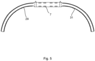
- the submarine power cable system 1 may comprise a plurality of bend restrictors 29, 31 configured to restrict bending of the cables 3, 5a, and 5b when the rigid submarine power cable joint 7 with the cables 3, 5a, and 5b connected thereto is moved, for example when the rigid submarine power cable joint 7 is lowered to the seabed 17.
- the bend restrictors 29, 31 are connected to the outer casing 7a and extend around a portion of a respective one of the cables 3, 5a and 5b and are configured to restrict bending of the cables 3, 5a and 5b in a region of e.g., up to 5 or 10 metres from the outer casing 7a in the direction of extension of the cables 3, 5a, 5b from the outer casing 7a.
- a first bend restrictor 29 may be connected to the first axial end face 7b of the outer casing 7a.
- the first bend restrictor 29 may extend around and along a portion of the multi-core dynamic submarine power cable 3 outside the outer casing 7a.
- Two second bend restrictors are connected to the second axial end face 7e of the outer casing 7a.
- Each second bend restrictor may extend around and along a portion of a respective one of the first static submarine power cable 5a and the second static submarine power cable 5b outside the outer casing 7a.
Priority Applications (5)
| Application Number | Priority Date | Filing Date | Title |
|---|---|---|---|
| EP22182293.5A EP4300740A1 (de) | 2022-06-30 | 2022-06-30 | Starre unterwasserstromkabelverbindung |
| JP2023100515A JP2024015974A (ja) | 2022-06-30 | 2023-06-20 | 剛性海底電力ケーブルジョイント |
| US18/340,502 US20240006865A1 (en) | 2022-06-30 | 2023-06-23 | Rigid submarine power cable joint |
| KR1020230083005A KR20240002942A (ko) | 2022-06-30 | 2023-06-27 | 강성 해저 전력 케이블 조인트 |
| CA3205140A CA3205140A1 (en) | 2022-06-30 | 2023-06-29 | Rigid submarine power cable joint |
Applications Claiming Priority (1)
| Application Number | Priority Date | Filing Date | Title |
|---|---|---|---|
| EP22182293.5A EP4300740A1 (de) | 2022-06-30 | 2022-06-30 | Starre unterwasserstromkabelverbindung |
Publications (1)
| Publication Number | Publication Date |
|---|---|
| EP4300740A1 true EP4300740A1 (de) | 2024-01-03 |
Family
ID=82494037
Family Applications (1)
| Application Number | Title | Priority Date | Filing Date |
|---|---|---|---|
| EP22182293.5A Pending EP4300740A1 (de) | 2022-06-30 | 2022-06-30 | Starre unterwasserstromkabelverbindung |
Country Status (5)
| Country | Link |
|---|---|
| US (1) | US20240006865A1 (de) |
| EP (1) | EP4300740A1 (de) |
| JP (1) | JP2024015974A (de) |
| KR (1) | KR20240002942A (de) |
| CA (1) | CA3205140A1 (de) |
Families Citing this family (1)
| Publication number | Priority date | Publication date | Assignee | Title |
|---|---|---|---|---|
| CN116249646A (zh) * | 2020-08-21 | 2023-06-09 | 原理动力有限公司 | 用于浮动平台的阵列间电缆 |
Citations (3)
| Publication number | Priority date | Publication date | Assignee | Title |
|---|---|---|---|---|
| SE1600089A1 (sv) * | 2016-03-11 | 2016-03-15 | Abb Technology Ltd | Rigid joint system for a submarine power cable and a three-core submarine power cable |
| CN209881368U (zh) * | 2019-04-08 | 2019-12-31 | 南京南瑞水利水电科技有限公司 | 一种集成电缆连接水下密封接头 |
| EP3336993B1 (de) * | 2016-12-19 | 2021-11-10 | Nexans | Kabelverstärkungshülse für eine unterwasserkabelverbindung |
-
2022
- 2022-06-30 EP EP22182293.5A patent/EP4300740A1/de active Pending
-
2023
- 2023-06-20 JP JP2023100515A patent/JP2024015974A/ja active Pending
- 2023-06-23 US US18/340,502 patent/US20240006865A1/en active Pending
- 2023-06-27 KR KR1020230083005A patent/KR20240002942A/ko unknown
- 2023-06-29 CA CA3205140A patent/CA3205140A1/en active Pending
Patent Citations (3)
| Publication number | Priority date | Publication date | Assignee | Title |
|---|---|---|---|---|
| SE1600089A1 (sv) * | 2016-03-11 | 2016-03-15 | Abb Technology Ltd | Rigid joint system for a submarine power cable and a three-core submarine power cable |
| EP3336993B1 (de) * | 2016-12-19 | 2021-11-10 | Nexans | Kabelverstärkungshülse für eine unterwasserkabelverbindung |
| CN209881368U (zh) * | 2019-04-08 | 2019-12-31 | 南京南瑞水利水电科技有限公司 | 一种集成电缆连接水下密封接头 |
Non-Patent Citations (1)
| Title |
|---|
| WEERHEIM RUBEN: "Development of dynamic power cables for commercial floating wind farms", REPORT LITERATURE ASSIGNMENT, 12 November 2018 (2018-11-12), XP055794185, Retrieved from the Internet <URL:https://repository.tudelft.nl/islandora/object/uuid:487ba1e5-2764-4e96-808c-a9ee2772219d/datastream/OBJ/download> [retrieved on 20210412] * |
Also Published As
| Publication number | Publication date |
|---|---|
| US20240006865A1 (en) | 2024-01-04 |
| KR20240002942A (ko) | 2024-01-08 |
| JP2024015974A (ja) | 2024-02-06 |
| CA3205140A1 (en) | 2023-12-30 |
Similar Documents
| Publication | Publication Date | Title |
|---|---|---|
| US9029704B2 (en) | Electric power cable | |
| US10056171B2 (en) | Submarine cable and multilayer tape for impermeable layer of same | |
| US11232886B2 (en) | Reinforced submarine power cable | |
| US9722406B2 (en) | Undersea cable, undersea cable installation structure, and method for installing undersea cable | |
| EP3323181B1 (de) | Offshore-kabel mit variabler länge und verfahren zur installation | |
| EP1691378A2 (de) | Tiefwassersignalkabel | |
| US20240006865A1 (en) | Rigid submarine power cable joint | |
| US9136040B2 (en) | Joint including two sections of a power cable and a method for joining two sections of a power cable | |
| EP3488448B1 (de) | Isoliertes tiefseekabel | |
| EP4163933A1 (de) | Dynamisches und statisches unterwasserkabel mit durchgehender drahtseele und herstellungsverfahren dafür | |
| US20220235744A1 (en) | Method of installing a transmission cable arrangement | |
| US20120033928A1 (en) | Repair box for optical fibre composite electric power cable | |
| US5235137A (en) | Buoyant cable | |
| EP0646817A2 (de) | Kompositkabelverbinder | |
| JP2022517880A (ja) | 電力ケーブル、その製造方法、およびその使用 | |
| US20230111135A1 (en) | Wet Design High Voltage Submarine Field and Repair Joint | |
| EP4309991A1 (de) | Offshore-verankerungsstruktur zum verbinden einer oberfläche mit einem unterwasseranker und zugehörige offshore-anlage | |
| NO20210762A1 (en) | An umbilical cable system and appurtenant method | |
| EP1325373B1 (de) | Verfahren und einrichtung zur sicherstellung einer zufriedenstellenden zugstärke beim spleissen eines unterwasserkabels | |
| BR112019016069A2 (pt) | Cabo |
Legal Events
| Date | Code | Title | Description |
|---|---|---|---|
| PUAI | Public reference made under article 153(3) epc to a published international application that has entered the european phase |
Free format text: ORIGINAL CODE: 0009012 |
|
| STAA | Information on the status of an ep patent application or granted ep patent |
Free format text: STATUS: THE APPLICATION HAS BEEN PUBLISHED |
|
| AK | Designated contracting states |
Kind code of ref document: A1 Designated state(s): AL AT BE BG CH CY CZ DE DK EE ES FI FR GB GR HR HU IE IS IT LI LT LU LV MC MK MT NL NO PL PT RO RS SE SI SK SM TR |