EP4300410B1 - Self-learning image geometrical distortion correction - Google Patents
Self-learning image geometrical distortion correction Download PDFInfo
- Publication number
- EP4300410B1 EP4300410B1 EP22181939.4A EP22181939A EP4300410B1 EP 4300410 B1 EP4300410 B1 EP 4300410B1 EP 22181939 A EP22181939 A EP 22181939A EP 4300410 B1 EP4300410 B1 EP 4300410B1
- Authority
- EP
- European Patent Office
- Prior art keywords
- room
- camera
- image
- floor
- bottom portions
- Prior art date
- Legal status (The legal status is an assumption and is not a legal conclusion. Google has not performed a legal analysis and makes no representation as to the accuracy of the status listed.)
- Active
Links
Images

Classifications
-
- G—PHYSICS
- G06—COMPUTING OR CALCULATING; COUNTING
- G06T—IMAGE DATA PROCESSING OR GENERATION, IN GENERAL
- G06T5/00—Image enhancement or restoration
- G06T5/80—Geometric correction
-
- G—PHYSICS
- G06—COMPUTING OR CALCULATING; COUNTING
- G06T—IMAGE DATA PROCESSING OR GENERATION, IN GENERAL
- G06T17/00—Three-dimensional [3D] modelling for computer graphics
-
- G—PHYSICS
- G06—COMPUTING OR CALCULATING; COUNTING
- G06T—IMAGE DATA PROCESSING OR GENERATION, IN GENERAL
- G06T5/00—Image enhancement or restoration
- G06T5/50—Image enhancement or restoration using two or more images, e.g. averaging or subtraction
-
- G—PHYSICS
- G06—COMPUTING OR CALCULATING; COUNTING
- G06T—IMAGE DATA PROCESSING OR GENERATION, IN GENERAL
- G06T3/00—Geometric image transformations in the plane of the image
- G06T3/04—Context-preserving transformations, e.g. by using an importance map
- G06T3/047—Fisheye or wide-angle transformations
-
- G—PHYSICS
- G06—COMPUTING OR CALCULATING; COUNTING
- G06V—IMAGE OR VIDEO RECOGNITION OR UNDERSTANDING
- G06V10/00—Arrangements for image or video recognition or understanding
- G06V10/20—Image preprocessing
- G06V10/24—Aligning, centring, orientation detection or correction of the image
- G06V10/243—Aligning, centring, orientation detection or correction of the image by compensating for image skew or non-uniform image deformations
-
- G—PHYSICS
- G06—COMPUTING OR CALCULATING; COUNTING
- G06V—IMAGE OR VIDEO RECOGNITION OR UNDERSTANDING
- G06V20/00—Scenes; Scene-specific elements
- G06V20/50—Context or environment of the image
- G06V20/52—Surveillance or monitoring of activities, e.g. for recognising suspicious objects
-
- H—ELECTRICITY
- H04—ELECTRIC COMMUNICATION TECHNIQUE
- H04N—PICTORIAL COMMUNICATION, e.g. TELEVISION
- H04N5/00—Details of television systems
- H04N5/222—Studio circuitry; Studio devices; Studio equipment
- H04N5/262—Studio circuits, e.g. for mixing, switching-over, change of character of image, other special effects ; Cameras specially adapted for the electronic generation of special effects
- H04N5/2628—Alteration of picture size, shape, position or orientation, e.g. zooming, rotation, rolling, perspective, translation
-
- B—PERFORMING OPERATIONS; TRANSPORTING
- B60—VEHICLES IN GENERAL
- B60R—VEHICLES, VEHICLE FITTINGS, OR VEHICLE PARTS, NOT OTHERWISE PROVIDED FOR
- B60R2300/00—Details of viewing arrangements using cameras and displays, specially adapted for use in a vehicle
- B60R2300/60—Details of viewing arrangements using cameras and displays, specially adapted for use in a vehicle characterised by monitoring and displaying vehicle exterior scenes from a transformed perspective
- B60R2300/607—Details of viewing arrangements using cameras and displays, specially adapted for use in a vehicle characterised by monitoring and displaying vehicle exterior scenes from a transformed perspective from a bird's eye viewpoint
-
- G—PHYSICS
- G06—COMPUTING OR CALCULATING; COUNTING
- G06T—IMAGE DATA PROCESSING OR GENERATION, IN GENERAL
- G06T2207/00—Indexing scheme for image analysis or image enhancement
- G06T2207/10—Image acquisition modality
- G06T2207/10016—Video; Image sequence
-
- G—PHYSICS
- G06—COMPUTING OR CALCULATING; COUNTING
- G06V—IMAGE OR VIDEO RECOGNITION OR UNDERSTANDING
- G06V10/00—Arrangements for image or video recognition or understanding
- G06V10/20—Image preprocessing
- G06V10/24—Aligning, centring, orientation detection or correction of the image
Definitions
- the present disclosure relates to distortion correction of images of a scene.
- the present disclosure relates to self-learning distortion correction of images captured by a camera having a non-rectilinear lens, such as e.g. a fisheye lens.
- a single camera is able to capture a larger part of a scene, and a wide-angle lens can be used for this purpose.
- Such wide-angle lenses are often non-rectilinear and thereby produce strong optical distortion of the image, such that lines or other objects in the scene which are straight end up being curved or warped in an image of the scene captured using such a lens.
- a non-rectilinear lens is a so-called fisheye lens, which is capable of producing e.g. a hemispherical image of a scene, and which often has a wide angle of view exceeding e.g. 90 degrees, 180 degrees or even 270 degrees.
- a monitoring camera mounted in e.g. a ceiling of a room, and configured to capture most or all of the room below the ceiling using a fisheye lens.
- a fisheye lens By being able to capture more of what is happening around the camera, such cameras provide an improved situational awareness compared to e.g. regular pan/tilt/zoom (PTZ) cameras.
- PTZ pan/tilt/zoom
- JP 6577557 B2 discloses that lens distortion may be corrected for based on estimated distances to corners of a room detected by boundary line detection (and boundary/wall line detection is also discussed in US 2020/111250 ).
- WO2022/238933A1 is a document falling under Art.54(3) EPC that also discloses a method and system for calibrating a camera to correct for perspective and lens distortion.
- the present disclosure provides an improved method of distortion correction in an image of a scene captured by a camera having a non-rectilinear lens, a device configured to perform such a method, and a computer program and computer program product as defined in the accompanying independent claims.
- Various embodiments of the improved method, device, computer program and computer program product are defined in the accompanying dependent claims.
- a floor (or ground) of the room is any horizontal surface on/across which e.g. people, animals or other objects normally walk/move.
- a wall is a vertical surface which is arranged around a periphery of the floor, and which often extends perpendicular to the floor.
- bottom portions can for example include feet (of animals or persons), wheels (of e.g. robotic vacuum cleaners, or similar), or any other part of an object which comes into contact with the floor when the object moves in the room.
- the 3D model of the room can be built automatically and without the need for manual segmentation of the image. As mentioned earlier herein, this may be particularly useful in larger installations of multiple cameras, as each camera may, using the solution of the present disclosure, self-learn how to model the room and then do the required distortion correction.
- the non-rectilinear lens (of the camera) may be a fisheye lens.
- the bottom portions may include feet of the objects (such as feet of humans, or feet of animals).
- the step ii) may include determining where the bottom portions of the one or more objects having moved over the floor of the room are located in the at least some of the multiple images by identifying one or more keypoints of the one or more objects.
- a "keypoint" may e.g. be an identified foot, knee, leg, or any other feature of an object in an image, and the location of the actual foot may be estimated based on the positions of these keypoints. For example, if knowing where e.g. a knee and/or hip of a person sitting in a sofa are/is located, the position of the foot may be calculated even if the foot is not visible in the image of the room. This may be a likely scenario if there is e.g. a table placed in front of the sofa, and allows the position of the foot to be inferred anyways, and used to determine the boundary of the floor.
- an area of the at least some of the multiple images is considered to belong to the floor of the room if a number of bottom portions having moved in the area during a finite time interval exceeds a threshold value. Requiring the detection of multiple bottom portions in a same area before classifying the area as part of the floor of the scene may e.g. improve confidence that the area is in fact part of the floor.
- the camera may be arranged in a ceiling of the room.
- the camera may e.g. be arranged such that its optical axis faces directly towards the floor, e.g. if the ceiling extends in a plane parallel with the plane of the floor, such that e.g. the optical axis of the camera is perpendicular to the plane of the floor.
- a device for distortion correction in an image of a room captured by a camera having a non-rectilinear lens includes processing circuitry.
- the processing circuitry is configured to cause the device to perform the method of the first aspect or any embodiment thereof described and discussed herein.
- the device may e.g. include a memory storing instructions that, when executed by the processing circuitry of the device, causes the device to perform the method. That the device is "configured to" perform the steps of the method thus means, in such an embodiment, that the processing circuitry is configured to read and execute the instructions stored in the memory.
- the device may be the camera having the non-rectilinear lens, such as e.g. a fisheye lens camera or similar.
- a computer program for distortion correction in an image of a scene captured by a camera having a non-rectilinear lens includes computer code that, when running on processing circuitry of a device, causes the device to perform the method of the first aspect or any embodiment thereof described and discussed herein.
- a computer-readable storage medium (which may be included as part of a computer program product), on which a computer program according to the third aspect (or any embodiment thereof discussed and disclosed herein) is stored.
- the computer-readable storage medium may e.g. be non-transitory, and be provided as e.g. a hard disk drive (HDD), solid state drive (SDD), USB flash drive, SD card, CD/DVD, and/or as any other storage medium capable of non-transitory storage of data.
- the computer-readable storage medium may be transitory and e.g. correspond to a signal (electrical, optical, mechanical, or similar) present on e.g. a communication link, wire, or similar means of signal transferring.
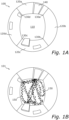
- FIG. 1A schematically illustrates an image 100 of a scene captured from above.
- the scene in this particular example, is of a room.
- the image 100 has been captured by a camera which has a non-rectilinear lens (such as e.g. a fisheye lens), the image 100 is thus warp such that straight lines are shown as curved lines, etc.
- the camera is envisaged as being mounted in a ceiling (not shown) of the room, and arranged with its optical axis facing directly towards a floor 110 of the room.
- the floor 110 is surrounded by four walls 120a-d, which project perpendicularly upwards from the floor 110 and are such that they form four corners 130a-d at locations where the floor 110 and respective walls meet.
- door 140 provided in the wall 120a, through which door objects may enter/exit the room.
- the room was empty (except for e.g. furniture, wall decorations, or similar), i.e. there were no persons, animals or other mobile objects within the room.
- the lines joining the corners together along the floor 110 appear to be curved/warped, due to the projection of the non-rectilinear lens of the camera on the image sensor of the camera. This applies also to most other lines in the image 100, which are warped/curved in the image 100 due to the distortion introduced by the lens of the camera. There is therefore a desire to correct for such distortion, such that e.g. lines which are straight in the real world remains straight also in an image depicting the scene.
- an operator would have to manually identify which part of the image 100 that belongs to the floor 110 (i.e. the horizontal surface of the scene shown in the image 100).
- the operator may perform such a task by (using a graphical user interface showing the image 100) e.g. tracing along the curved lines joining the four corners 130-d, and/or by manually indicating e.g. the area of the image 100 corresponding to the four walls 120a-d and the door 140, i.e. the vertical surfaces of the scene.
- a graphical user interface showing the image 100 e.g. tracing along the curved lines joining the four corners 130-d, and/or by manually indicating e.g. the area of the image 100 corresponding to the four walls 120a-d and the door 140, i.e. the vertical surfaces of the scene.
- such a process is time-consuming, and potentially not even tractable if there are many (e.g. hundreds) of cameras that are to be configured and prepared for distortion correction in a larger camera installation.
- Figure 1B schematically illustrates an overlay of multiple images 101 of the room captured over time, wherein a plurality of footprints 150 indicate where bottom portions of one or more objects having moved over a horizontal surface/floor in the scene have been located. From image 101, it is for example apparent that one or more objects have entered through the door 140 and moved to an object in the room (such as a cabin, wall, or similar), and then exited through the door 140 again.
- the footprints 150 may not necessarily be actual footprints left after persons (as caused e.g. by dirt under shoes, rubber markings, or similar), but instead serve to illustrate/symbolize where the bottom portions (such as e.g. feet) of these objects have been determined over time. Keypoint detection may e.g.
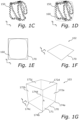
- Figure 1C schematically illustrates how the bottom portions have moved in the scene over time, using the footprints 150 for illustration.
- the footprints 150 are plotted in an (x,y)-coordinate system, such that each footprint 150 is located at a particular (x,y)-coordinate.
- Figure 1D schematically illustrates the same footprints 150 as in Figure 1C , but with a dashed shape 160 indicating the extension of the footprints in a plane of the floor 110.
- Figure 1E schematically illustrates how, based on known parameters of the camera, a rectangular boundary 170 is defined based on the extension 160 of the footprints 150. This may e.g. be done based on knowledge about how the non-rectangular lens refracts light originating from different angles. For e.g. a fisheye lens, how the lens refracts the light is based on a distance between a pixel (on the image sensor of the camera used to capture the image of the scene) and an optical center of the lens (a center from which an optical axis of the lens/camera extends), and may not require e.g. knowledge about an installation height of the camera above the floor 110.
- the boundary 170 may e.g.
- Figure 1F schematically illustrates how, after having identified the boundary 170, the boundary 170 is used as a horizontal surface of a three-dimensional model 102. As shown in Figure 1F , the three-dimensional model 102 is unfinished, and needs to be completed with one or more vertical surfaces.
- Figure 1G schematically illustrates the completion of the three-dimensional model 102 in order to form a completed three-dimensional model 103.
- vertical surfaces in form of walls 172a-d have been added/defined, such that the walls 172a-d are defined around the boundary 170.
- the walls 172a-d are added such that they extend perpendicularly away from the plane of the boundary 170, i.e. in a positive z-direction as shown in Figure 1G .
- the three-dimensional model 103 thus includes a floor 171 bounded by the boundary 170, and the four walls 172a-d which intersects each other and the floor 171 at four corners 174a-174d.
- the walls 172a-d have a same height h.
- the three-dimensional model 104 is thus created under the assumption that areas of an image in which objects have not moved are statistically likely to belong to e.g. walls of a room.
- the parameter h may be tuned as desired to emulate a height of e.g. the room.
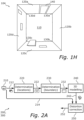
- Figure 1H schematically illustrates once again a top-view of the room, but where the image 100 of Figure 1A has now been projected on the three-dimensional model 103.
- the resulting image 104 is a distortion corrected version of the image 100, as can be seen from that e.g. the lines joining the four corners 130a-d are no longer as warped/curved as before.
- performing the projection of the image 100 onto the three-dimensional model 103 may e.g. be based on knowledge about an orientation between the floor 171 and the camera, which may e.g. be obtained by assuming that the optical axis of the camera/lens is orthogonal to the floor 171.
- the assumed position of the camera when performing the projection of the image 100 onto the three-dimensional model 103 may on purpose be changed from its true location, e.g. to correct for the camera not being exactly centered within the ceiling of the room, or similar.
- Changing the assumed position of the camera may e.g. help to obtain a similar number of pixels on both sides (horizontal and/or vertical) of the resulting image 104.
- the assumed height of the camera above the floor of e.g. the room may also be changed such that it does not match the true height, when performing the projection.
- This may be particularly interesting if e.g. wanting to change a perspective of the resulting image 104.
- a three-dimensional model may be constructed which may then be used to perform the projection of the image 100 onto this three-dimensional model (such as the model 103).
- Exactly how the projection is then performed may vary based on e.g. a desired perspective, and on e.g. a desired viewpoint (e.g. a desired/assumed location of the camera vis-à-vis the horizontal surface.
- the accuracy of the proposed method may of course depend on whether objects moving in the scene visit all parts of e.g. a floor or not. If no objects move across a particular part of the floor in the multiple images of the scene provided to the proposed method, the resulting three-dimensional model of the scene will likely be too small, and objects outside of the envisaged floor will appear warped. However, such effects can be reduced by analyzing more images of the scene, if assuming that the likelihood of each area of a floor being visited by at least one object increases with time.
- true positions of bottom portions of the objects may be identified also in areas of the floor which are hidden from the camera, due to e.g. furniture or other objects being arranged between the floor and the camera. This further improves the chance of obtaining an accurate estimate of e.g. a true floor of a room.
- An envisaged usage scenario is e.g. when multiple fisheye cameras are installed to cover a larger room or e.g. hallway, and where manual configuration of each camera would be substantially time-consuming.
- the cameras can be installed and then be allowed to each learn what parts of its images correspond to e.g. floors and walls.
- Each camera can then, based thereon, generate its own three-dimensional model of the part of the scene it is responsible for capturing, and then use this three-dimensional model to project its captured images in order to perform distortion correction.
- the floor does not necessarily need to be square or rectangular, but can also have other shapes.
- one or more walls of a room may be curved.
- a wall does not necessarily need to meet another wall at a go-degree angle. The only assumption made is that the walls extend perpendicularly from the floor.
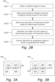
- Figure 2A schematically illustrates, using various functional units, various embodiments of a method 200 for distortion correction as envisaged herein, while Figure 2B schematically illustrates a flow of such a method.
- Figure 2A also serves to illustrate an envisaged device 300 for performing the method, as will be described in more detail later herein with reference to Figures 3A to 3C .
- a camera 210 is arranged to capture a scene (e.g. a room).
- the camera 210 has a non-rectilinear lens, such as e.g. a fisheye lens, such that a field-of-view of the camera 210 is sufficiently large for the camera 210 to capture a broader section of the scene.
- Multiple images 212 of the scene captured by the camera 210 are provided to a first determination module 220.
- the first determination module 220 receives the multiple images 212 of the scene from the camera 210.
- the camera 210 may send the multiple images at once, or e.g. send one image at a time, e.g. as soon as each image is captured.
- the first determination module 220 is configured to estimate/determine (in a step S202) locations of bottom portions of one or more objects having moved over a horizontal surface in the scene. This may be performed e.g. by using keypoints, and/or from identifying the bottom portions of the one or more objects directly.
- the first determination module 220 may e.g. be configured to identify feet of humans, feet of animals, and/or wheels of e.g.
- the first determination module 220 sends the estimated location 222 to a second determination module 230.
- the first determination module 220 may also wait until it has determined multiple locations of bottom portions, and then send these multiple locations to the second determination module 230 at a same time.
- the second determination module 230 receives the multiple locations 222 of bottom portions from the first determination module 220, in order to gather statistics about how objects, and in particular their bottom portions, move in the scene over time. In particular, the second determination module 230 may focus on where the objects move, i.e. which part of the room their respective bottom portions visits. In a step S203, the second determination module 230 uses such statistics to determine/estimate a boundary of the floor of the room. Once the boundary of the floor of the room is determined, the second determination module 230 sends the determined boundary 232 to a 3D model module 240. The second determination 230 module waits until a number of bottom portions having moved in a particular area of the image exceeds a threshold value, before considering the particular area as a floor of the room.
- multiple bottom portions may not necessarily mean bottom portions of different objects, but may also be one or more bottom portions of a same object repeatedly being identified as located in the particular area. More generally, it is not necessarily needed to differentiate between different objects, and a method capable of only identify a bottom portion (without also identifying to which particular object the bottom portion belongs) may thus also be used to implement the envisaged method.
- the 3D modelling module 240 receives the determined boundary 232 from the second determination module 230, and is configured to generate (in a step S204) a three-dimensional model of the room captured by the camera 210 by defining one or more walls around the determined boundary of the floor. Once the three-dimensional model has been generated, the 3D modelling module 240 sends the three-dimensional model 242 to a correction module 250.
- the three-dimensional model may for example be defined by a plurality of coordinates representative of the boundary, and a plurality of coordinates representative of the walls.
- the floor may e.g. be represented as a polygon
- the walls may be represented as e.g.
- the correction module 250 receives the three-dimensional model 242 from the 3D modelling module 240, and performs (in a step S205) correction of a distortion of one or more images 214 captured by the camera 210 by projecting the one or more images onto the three-dimensional model received from the 3D modelling module 240.
- the one or more images (capturing a same room/scene) on which the correction module 250 applies the distortion may for example be received directly from the camera 210 as one or more images 214.
- the one or more images on which distortion correction is to be made may e.g. be sent from any other module in possession of such images.
- the correction module 250 may e.g. output a corrected image 252.
- the corrected image 252 may e.g. be included as part of a video stream, and may e.g. replace the corresponding non-corrected image or be provided in addition to the non-corrected image.
- the image which is distortion corrected may not necessarily be a same image as one of those used to generate the three-dimensional model, but may instead be e.g. an image of the scene captured at a later instance than the multiple images used to generate the three-dimensional model.
- a device for performing distortion correction of an image captured using a camera having a non-rectilinear lens will now be described in more detail with reference to Figures 3A to 3C .
- FIG. 3A schematically illustrates, in terms of a number of functional units/modules/blocks, the components of various embodiments of a device 300 as envisaged herein.
- the device 300 includes processing circuitry 310.
- the processing circuitry 310 is provided using any combination of one or more of a suitable central processing unit (CPU), multiprocessor, microcontroller, digital signal processor (DSP), etc., capable of executing software instructions stored in a computer program product (not illustrated herein), e.g. in form of a computer-readable storage medium 320.
- the processing circuit 610 may further be provided as at least one application specific integrated circuit (ASIC), or field-programmable gate array (FPGA).
- ASIC application specific integrated circuit
- FPGA field-programmable gate array
- the processing circuitry 310 is configured to cause the device 300 to perform a set of operations, or steps, such as one or more of steps S201-S205 as disclosed above e.g. when describing the method 200 illustrated in Figures 2A and 2B .
- the storage medium 320 may store a set of operations
- the processing circuitry 310 may be configured to retrieve the set of operations from the storage medium 320 to cause the device 300 to perform the set of operations.
- the set of operations may be provided as a set of executable instructions.
- the processing circuitry 310 is thereby arranged to execute methods as disclosed herein e.g. with reference to Figures 2A and 2B .
- the storage medium 320 may also include persistent storage, which, for example, can be a memory in form of any single or combination of magnetic memory, optical memory, solid state memory or even remotely mounted memory.
- the device 300 may further include a communications interface 330 for communications with other entities, functions, nodes, and devices, such as e.g. the camera 210.
- the communications interface 330 may allow the device 300 to communicate with the camera 210 in order to receive the multiple images of the scene used to generate the three-dimensional model of the scene.
- the communications interface 330 may include one or more transmitters and receivers, including analogue and/or digital components.
- the device 300 may in some embodiments be the camera 210 itself, and the communications interface 330 may e.g. include any necessary circuitry to e.g. allow the processing circuitry 310 of the device/camera 300 to access image data produced by an image sensor (not shown) of the device/camera 300.
- the processing circuitry 310 controls the general operation of the device 300 e.g. by sending data and control signals to the communications interface 330 and the storage medium/memory 320, by receiving data and reports from the communications interface 330, and by retrieving data and instructions from the storage medium 320.
- Other components, as well as their related functionality, of the device 300 may of course also be included (as illustrated by the dashed box 340), but any description thereof is omitted in order not to obscure the concepts presented herein.
- a communications bus 350 is included and configured to allow the various units 310, 320 and 330 (and optionally also 340) to exchange data and information with each other as required.
- FIG 3B schematically illustrates, in terms of a number of functional modules 301-305, the components of a device 300 according to various embodiments of the present disclosure.
- the device 300 includes at least a first determination module 301 configured to perform step S202 of the method 200 described with reference to Figures 2A and 2B (such as e.g. the first determination module 220), a second determination module 302 configured to perform step S203 (such as e.g. the second determination module 230), a 3D modelling module 303 configured to perform step S204 (such as e.g. the 3D modelling module 240), and a distortion correction module 304 configured to perform step S205 (such as e.g. the correction module 250).
- a first determination module 301 configured to perform step S202 of the method 200 described with reference to Figures 2A and 2B
- a second determination module 302 configured to perform step S203 (such as e.g. the second determination module 230)
- a 3D modelling module 303 configured to perform step S204 (such as
- each functional module 301-304 may be implemented in hardware or in software.
- one or more or all functional modules 301-304 may be implemented by the processing circuitry 310, possibly in cooperation with the communications interface 330 and/or the storage medium 320.
- the processing circuitry 310 may thus be arranged to from the storage medium 320 fetch instructions as provided by a functional modules 301-304, and to execute these instructions and thereby perform any steps of the method 200 performed by the device 300 as disclosed herein.
- each module 301-304 may be separate from the other modules.
- one, more or all of the modules 310-304 maybe implemented as parts of a same, physical module, or similar.
- the device 300 may further include additional functional modules (illustrated by the dashed box 305) as required to perform other tasks of the device 300, e.g. as defined by the accompanying dependent claims.
- a communications bus 352 (logical or physical) is provided to allow the various functional modules 301-304 (and optionally 305) to communicate/exchange data and information as required.
- FIG 3C schematically illustrates an embodiment of a camera 300 as envisaged herein, i.e. when the device 300 described with reference to Figures 3A and 3B is in fact the camera 300 used to capture the multiple images of the scene.
- the camera 300 maybe a fisheye camera having a fisheye lens 370.
- the camera 300 has an optical axis 372, such that when capturing an image of a scene, a point of the scene aligned with the optical axis 372 preferably corresponds to a pixel in the center of the captured image.
- the camera 300 includes e.g. the processing circuitry 310 as described above, and may also include e.g. the memory (not shown) 320, and similar.
- the camera 300 is configured to be mounted in a ceiling of e.g. a room, such that the optical axis 372 is e.g. orthogonal to a floor of the room.
- the present disclosure also provides a computer program and computer program product as already described herein.
- the computer program product includes a computer-readable storage medium on which the envisaged computer program is stored.
- the computer program includes computer code that, when run on processing circuitry (such as 310) of a device (such as 300), the computer code causes the device to perform any method disclosed and discussed herein, e.g. by executing the steps S201-S205 of the method 200 described with reference to Figures 2A and 2B . Consequently, the computer program and/or computer program product may thus provide the means for performing any steps of e.g. the method 200 and/or to make the envisaged device 300 operate as intended.
- the computer program product can be provided for example as an optical disc, such as a CD (compact disc) or a DVD (digital versatile disc) or a Blu-Ray disc.
- the computer program product could also be embodied as a memory, such as a random-access memory (RAM), a read-only memory (ROM), an erasable programmable read-only memory (EPROM), or an electrically erasable programmable read-only memory (EEPROM) and more particularly as a non-volatile storage medium of a device in an external memory such as a USB (Universal Serial Bus) memory or a Flash memory, such as a compact Flash memory.
- the computer program can be stored in any way which is suitable for the computer program product, i.e. on the computer-readable storage medium.
- the present disclosure provides an improved way of handling distortion correction in images captured by cameras having non-rectilinear lenses.
- the present disclosure provides a way of self-learning such a correction by observing how, or in particular where, bottom portions of objects (such as feet of humans) move in images of a scene, in order to determine what parts of an image of the scene that correspond to e.g. a floor of a room, and which other parts of the image that correspond to e.g. walls of the room, in order to generate a three-dimensional model which can be used to perform the correction.
- a camera to learn, over time, how to generate such a three-dimensional model, distortion in images captured by the camera may be corrected without requiring manual input from e.g. an operator, thus facilitating e.g. a process of installing multiple such cameras.
Landscapes
- Engineering & Computer Science (AREA)
- Physics & Mathematics (AREA)
- General Physics & Mathematics (AREA)
- Theoretical Computer Science (AREA)
- Multimedia (AREA)
- Geometry (AREA)
- Computer Graphics (AREA)
- Software Systems (AREA)
- Signal Processing (AREA)
- Image Processing (AREA)
- Studio Devices (AREA)
Priority Applications (4)
| Application Number | Priority Date | Filing Date | Title |
|---|---|---|---|
| EP22181939.4A EP4300410B1 (en) | 2022-06-29 | 2022-06-29 | Self-learning image geometrical distortion correction |
| US18/326,555 US12456178B2 (en) | 2022-06-29 | 2023-05-31 | Self-learning distortion correction |
| CN202310744619.2A CN117314762B (zh) | 2022-06-29 | 2023-06-21 | 自学习畸变校正 |
| JP2023102344A JP7589296B2 (ja) | 2022-06-29 | 2023-06-22 | 自己学習型歪み補正 |
Applications Claiming Priority (1)
| Application Number | Priority Date | Filing Date | Title |
|---|---|---|---|
| EP22181939.4A EP4300410B1 (en) | 2022-06-29 | 2022-06-29 | Self-learning image geometrical distortion correction |
Publications (3)
| Publication Number | Publication Date |
|---|---|
| EP4300410A1 EP4300410A1 (en) | 2024-01-03 |
| EP4300410C0 EP4300410C0 (en) | 2024-05-08 |
| EP4300410B1 true EP4300410B1 (en) | 2024-05-08 |
Family
ID=82492502
Family Applications (1)
| Application Number | Title | Priority Date | Filing Date |
|---|---|---|---|
| EP22181939.4A Active EP4300410B1 (en) | 2022-06-29 | 2022-06-29 | Self-learning image geometrical distortion correction |
Country Status (4)
| Country | Link |
|---|---|
| US (1) | US12456178B2 (enExample) |
| EP (1) | EP4300410B1 (enExample) |
| JP (1) | JP7589296B2 (enExample) |
| CN (1) | CN117314762B (enExample) |
Families Citing this family (4)
| Publication number | Priority date | Publication date | Assignee | Title |
|---|---|---|---|---|
| WO2019099707A1 (en) * | 2017-11-16 | 2019-05-23 | Kite Pharma, Inc | Modified chimeric antigen receptors and methods of use |
| EP4600913B1 (en) * | 2024-02-09 | 2026-04-01 | Axis AB | Method and system for calibration of detection thresholds in video object detection |
| WO2025253553A1 (ja) * | 2024-06-05 | 2025-12-11 | Ntt株式会社 | 三次元再構成装置 |
| EP4727113A1 (en) * | 2024-10-10 | 2026-04-15 | Axis AB | A method for controlling an image processing stage for processing image data captured by a surveillance camera |
Citations (1)
| Publication number | Priority date | Publication date | Assignee | Title |
|---|---|---|---|---|
| WO2022238933A1 (en) * | 2021-05-11 | 2022-11-17 | Ssy.Ai Inc | Method to automatically calibrate cameras and generate maps |
Family Cites Families (12)
| Publication number | Priority date | Publication date | Assignee | Title |
|---|---|---|---|---|
| US20130201300A1 (en) * | 2012-01-30 | 2013-08-08 | Panasonic Corporation | Imaging apparatus |
| TWI555378B (zh) * | 2015-10-28 | 2016-10-21 | 輿圖行動股份有限公司 | 一種全景魚眼相機影像校正、合成與景深重建方法與其系統 |
| CN106600546B (zh) * | 2016-11-14 | 2020-12-22 | 深圳市Tcl高新技术开发有限公司 | 一种超广角摄像头畸变校正方法及系统 |
| JP6577557B2 (ja) * | 2017-12-08 | 2019-09-18 | 株式会社Lifull | 情報処理装置、情報処理方法、及び情報処理用プログラム |
| CN108961395B (zh) * | 2018-07-03 | 2019-07-30 | 上海亦我信息技术有限公司 | 一种基于拍照重建三维空间场景的方法 |
| US10535146B1 (en) * | 2018-07-16 | 2020-01-14 | Accel Robotics Corporation | Projected image item tracking system |
| JP7338182B2 (ja) | 2019-03-19 | 2023-09-05 | 株式会社リコー | 行動認識装置、行動認識方法及びプログラム |
| EP3983996A1 (en) | 2019-06-17 | 2022-04-20 | Ariel Ai, Inc. | Scene reconstruction in three-dimensions from two-dimensional images |
| CN110310577B (zh) | 2019-07-05 | 2021-01-01 | 武汉华星光电半导体显示技术有限公司 | 显示面板及其制备方法 |
| US20210127059A1 (en) * | 2019-10-29 | 2021-04-29 | Microsoft Technology Licensing, Llc | Camera having vertically biased field of view |
| CN111815714B (zh) * | 2020-07-01 | 2024-05-17 | 广州视源电子科技股份有限公司 | 一种鱼眼相机标定方法、装置、终端设备及存储介质 |
| KR102404867B1 (ko) * | 2020-12-16 | 2022-06-07 | 한국전자기술연구원 | 3차원 거리정보를 이용한 랩어라운드뷰 영상제공장치 및 방법 |
-
2022
- 2022-06-29 EP EP22181939.4A patent/EP4300410B1/en active Active
-
2023
- 2023-05-31 US US18/326,555 patent/US12456178B2/en active Active
- 2023-06-21 CN CN202310744619.2A patent/CN117314762B/zh active Active
- 2023-06-22 JP JP2023102344A patent/JP7589296B2/ja active Active
Patent Citations (1)
| Publication number | Priority date | Publication date | Assignee | Title |
|---|---|---|---|---|
| WO2022238933A1 (en) * | 2021-05-11 | 2022-11-17 | Ssy.Ai Inc | Method to automatically calibrate cameras and generate maps |
Also Published As
| Publication number | Publication date |
|---|---|
| CN117314762A (zh) | 2023-12-29 |
| US20240005460A1 (en) | 2024-01-04 |
| EP4300410C0 (en) | 2024-05-08 |
| EP4300410A1 (en) | 2024-01-03 |
| US12456178B2 (en) | 2025-10-28 |
| CN117314762B (zh) | 2024-12-31 |
| JP2024007396A (ja) | 2024-01-18 |
| JP7589296B2 (ja) | 2024-11-25 |
Similar Documents
| Publication | Publication Date | Title |
|---|---|---|
| EP4300410A1 (en) | Self-learning image geometrical distortion correction | |
| US7321386B2 (en) | Robust stereo-driven video-based surveillance | |
| US8098302B2 (en) | Stain detection system | |
| CN113052907B (zh) | 一种动态环境移动机器人的定位方法 | |
| JP5180733B2 (ja) | 移動物体追跡装置 | |
| KR101776621B1 (ko) | 에지 기반 재조정을 이용하여 이동 로봇의 위치를 인식하기 위한 장치 및 그 방법 | |
| CN104574406B (zh) | 一种360度全景激光与多个视觉系统间的联合标定方法 | |
| US9466107B2 (en) | Bundle adjustment based on image capture intervals | |
| US10602125B2 (en) | Camera-parameter-set calculation apparatus, camera-parameter-set calculation method, and recording medium | |
| EP3502822B1 (en) | Moving-robot and control method for the same | |
| JP6584123B2 (ja) | 画像処理装置、画像処理方法、及びプログラム | |
| KR20110011424A (ko) | 이동 로봇의 위치 인식 및 주행 제어 방법과 이를 이용한 이동 로봇 | |
| KR20180088788A (ko) | 다중-방향성 카메라를 이용한 공간 매핑 | |
| CN108122412B (zh) | 用于监控机器人检测车辆乱停的方法 | |
| TW202242803A (zh) | 定位方法、裝置、電子設備及儲存媒體 | |
| JP7030451B2 (ja) | 画像処理装置 | |
| CN111168685A (zh) | 机器人控制方法、机器人和可读存储介质 | |
| CN115861443B (zh) | 一种多相机内参标定方法、装置、电子设备及存储介质 | |
| CN112270753B (zh) | 三维建图方法及装置、电子设备 | |
| CN112859836B (zh) | 一种自主移动设备、校正方法及计算机存储介质 | |
| US20240335080A1 (en) | Mobile robot | |
| JP7101080B2 (ja) | 画像処理装置 | |
| CN114723799B (zh) | 检测方法、装置、移动机器人及存储介质 | |
| JP7188934B2 (ja) | 画像処理装置 | |
| KR20230076243A (ko) | 산업현장의 안전사고 예방방법 및 그 장치 |
Legal Events
| Date | Code | Title | Description |
|---|---|---|---|
| STAA | Information on the status of an ep patent application or granted ep patent |
Free format text: STATUS: EXAMINATION IS IN PROGRESS |
|
| PUAI | Public reference made under article 153(3) epc to a published international application that has entered the european phase |
Free format text: ORIGINAL CODE: 0009012 |
|
| 17P | Request for examination filed |
Effective date: 20230405 |
|
| AK | Designated contracting states |
Kind code of ref document: A1 Designated state(s): AL AT BE BG CH CY CZ DE DK EE ES FI FR GB GR HR HU IE IS IT LI LT LU LV MC MK MT NL NO PL PT RO RS SE SI SK SM TR |
|
| RIC1 | Information provided on ipc code assigned before grant |
Ipc: H04N 5/262 20060101ALN20231230BHEP Ipc: G06V 20/52 20220101ALI20231230BHEP Ipc: G06V 10/24 20220101ALI20231230BHEP Ipc: G06T 17/00 20060101ALI20231230BHEP Ipc: G06T 5/00 20240101ALI20231230BHEP Ipc: G06T 3/00 20240101AFI20231230BHEP |
|
| GRAP | Despatch of communication of intention to grant a patent |
Free format text: ORIGINAL CODE: EPIDOSNIGR1 |
|
| STAA | Information on the status of an ep patent application or granted ep patent |
Free format text: STATUS: GRANT OF PATENT IS INTENDED |
|
| RIC1 | Information provided on ipc code assigned before grant |
Ipc: H04N 5/262 20060101ALN20240112BHEP Ipc: G06V 20/52 20220101ALI20240112BHEP Ipc: G06V 10/24 20220101ALI20240112BHEP Ipc: G06T 17/00 20060101ALI20240112BHEP Ipc: G06T 5/00 20240101ALI20240112BHEP Ipc: G06T 3/00 20240101AFI20240112BHEP |
|
| INTG | Intention to grant announced |
Effective date: 20240219 |
|
| GRAS | Grant fee paid |
Free format text: ORIGINAL CODE: EPIDOSNIGR3 |
|
| GRAA | (expected) grant |
Free format text: ORIGINAL CODE: 0009210 |
|
| STAA | Information on the status of an ep patent application or granted ep patent |
Free format text: STATUS: THE PATENT HAS BEEN GRANTED |
|
| AK | Designated contracting states |
Kind code of ref document: B1 Designated state(s): AL AT BE BG CH CY CZ DE DK EE ES FI FR GB GR HR HU IE IS IT LI LT LU LV MC MK MT NL NO PL PT RO RS SE SI SK SM TR |
|
| REG | Reference to a national code |
Ref country code: GB Ref legal event code: FG4D |
|
| REG | Reference to a national code |
Ref country code: CH Ref legal event code: EP |
|
| REG | Reference to a national code |
Ref country code: DE Ref legal event code: R096 Ref document number: 602022003314 Country of ref document: DE |
|
| REG | Reference to a national code |
Ref country code: IE Ref legal event code: FG4D |
|
| U01 | Request for unitary effect filed |
Effective date: 20240508 |
|
| U07 | Unitary effect registered |
Designated state(s): AT BE BG DE DK EE FI FR IT LT LU LV MT NL PT SE SI Effective date: 20240515 |
|
| U20 | Renewal fee for the european patent with unitary effect paid |
Year of fee payment: 3 Effective date: 20240521 |
|
| PG25 | Lapsed in a contracting state [announced via postgrant information from national office to epo] |
Ref country code: IS Free format text: LAPSE BECAUSE OF FAILURE TO SUBMIT A TRANSLATION OF THE DESCRIPTION OR TO PAY THE FEE WITHIN THE PRESCRIBED TIME-LIMIT Effective date: 20240908 |
|
| PG25 | Lapsed in a contracting state [announced via postgrant information from national office to epo] |
Ref country code: HR Free format text: LAPSE BECAUSE OF FAILURE TO SUBMIT A TRANSLATION OF THE DESCRIPTION OR TO PAY THE FEE WITHIN THE PRESCRIBED TIME-LIMIT Effective date: 20240508 |
|
| PG25 | Lapsed in a contracting state [announced via postgrant information from national office to epo] |
Ref country code: GR Free format text: LAPSE BECAUSE OF FAILURE TO SUBMIT A TRANSLATION OF THE DESCRIPTION OR TO PAY THE FEE WITHIN THE PRESCRIBED TIME-LIMIT Effective date: 20240809 |
|
| PG25 | Lapsed in a contracting state [announced via postgrant information from national office to epo] |
Ref country code: ES Free format text: LAPSE BECAUSE OF FAILURE TO SUBMIT A TRANSLATION OF THE DESCRIPTION OR TO PAY THE FEE WITHIN THE PRESCRIBED TIME-LIMIT Effective date: 20240508 |
|
| PG25 | Lapsed in a contracting state [announced via postgrant information from national office to epo] |
Ref country code: PL Free format text: LAPSE BECAUSE OF FAILURE TO SUBMIT A TRANSLATION OF THE DESCRIPTION OR TO PAY THE FEE WITHIN THE PRESCRIBED TIME-LIMIT Effective date: 20240508 |
|
| PG25 | Lapsed in a contracting state [announced via postgrant information from national office to epo] |
Ref country code: PL Free format text: LAPSE BECAUSE OF FAILURE TO SUBMIT A TRANSLATION OF THE DESCRIPTION OR TO PAY THE FEE WITHIN THE PRESCRIBED TIME-LIMIT Effective date: 20240508 Ref country code: NO Free format text: LAPSE BECAUSE OF FAILURE TO SUBMIT A TRANSLATION OF THE DESCRIPTION OR TO PAY THE FEE WITHIN THE PRESCRIBED TIME-LIMIT Effective date: 20240808 Ref country code: IS Free format text: LAPSE BECAUSE OF FAILURE TO SUBMIT A TRANSLATION OF THE DESCRIPTION OR TO PAY THE FEE WITHIN THE PRESCRIBED TIME-LIMIT Effective date: 20240908 Ref country code: HR Free format text: LAPSE BECAUSE OF FAILURE TO SUBMIT A TRANSLATION OF THE DESCRIPTION OR TO PAY THE FEE WITHIN THE PRESCRIBED TIME-LIMIT Effective date: 20240508 Ref country code: GR Free format text: LAPSE BECAUSE OF FAILURE TO SUBMIT A TRANSLATION OF THE DESCRIPTION OR TO PAY THE FEE WITHIN THE PRESCRIBED TIME-LIMIT Effective date: 20240809 Ref country code: ES Free format text: LAPSE BECAUSE OF FAILURE TO SUBMIT A TRANSLATION OF THE DESCRIPTION OR TO PAY THE FEE WITHIN THE PRESCRIBED TIME-LIMIT Effective date: 20240508 Ref country code: RS Free format text: LAPSE BECAUSE OF FAILURE TO SUBMIT A TRANSLATION OF THE DESCRIPTION OR TO PAY THE FEE WITHIN THE PRESCRIBED TIME-LIMIT Effective date: 20240808 |
|
| PG25 | Lapsed in a contracting state [announced via postgrant information from national office to epo] |
Ref country code: CZ Free format text: LAPSE BECAUSE OF FAILURE TO SUBMIT A TRANSLATION OF THE DESCRIPTION OR TO PAY THE FEE WITHIN THE PRESCRIBED TIME-LIMIT Effective date: 20240508 |
|
| PG25 | Lapsed in a contracting state [announced via postgrant information from national office to epo] |
Ref country code: RO Free format text: LAPSE BECAUSE OF FAILURE TO SUBMIT A TRANSLATION OF THE DESCRIPTION OR TO PAY THE FEE WITHIN THE PRESCRIBED TIME-LIMIT Effective date: 20240508 Ref country code: SK Free format text: LAPSE BECAUSE OF FAILURE TO SUBMIT A TRANSLATION OF THE DESCRIPTION OR TO PAY THE FEE WITHIN THE PRESCRIBED TIME-LIMIT Effective date: 20240508 |
|
| PG25 | Lapsed in a contracting state [announced via postgrant information from national office to epo] |
Ref country code: SM Free format text: LAPSE BECAUSE OF FAILURE TO SUBMIT A TRANSLATION OF THE DESCRIPTION OR TO PAY THE FEE WITHIN THE PRESCRIBED TIME-LIMIT Effective date: 20240508 |
|
| PG25 | Lapsed in a contracting state [announced via postgrant information from national office to epo] |
Ref country code: SM Free format text: LAPSE BECAUSE OF FAILURE TO SUBMIT A TRANSLATION OF THE DESCRIPTION OR TO PAY THE FEE WITHIN THE PRESCRIBED TIME-LIMIT Effective date: 20240508 Ref country code: SK Free format text: LAPSE BECAUSE OF FAILURE TO SUBMIT A TRANSLATION OF THE DESCRIPTION OR TO PAY THE FEE WITHIN THE PRESCRIBED TIME-LIMIT Effective date: 20240508 Ref country code: RO Free format text: LAPSE BECAUSE OF FAILURE TO SUBMIT A TRANSLATION OF THE DESCRIPTION OR TO PAY THE FEE WITHIN THE PRESCRIBED TIME-LIMIT Effective date: 20240508 Ref country code: CZ Free format text: LAPSE BECAUSE OF FAILURE TO SUBMIT A TRANSLATION OF THE DESCRIPTION OR TO PAY THE FEE WITHIN THE PRESCRIBED TIME-LIMIT Effective date: 20240508 |
|
| PG25 | Lapsed in a contracting state [announced via postgrant information from national office to epo] |
Ref country code: MC Free format text: LAPSE BECAUSE OF FAILURE TO SUBMIT A TRANSLATION OF THE DESCRIPTION OR TO PAY THE FEE WITHIN THE PRESCRIBED TIME-LIMIT Effective date: 20240508 |
|
| REG | Reference to a national code |
Ref country code: DE Ref legal event code: R097 Ref document number: 602022003314 Country of ref document: DE |
|
| PLBE | No opposition filed within time limit |
Free format text: ORIGINAL CODE: 0009261 |
|
| STAA | Information on the status of an ep patent application or granted ep patent |
Free format text: STATUS: NO OPPOSITION FILED WITHIN TIME LIMIT |
|
| 26N | No opposition filed |
Effective date: 20250211 |
|
| PG25 | Lapsed in a contracting state [announced via postgrant information from national office to epo] |
Ref country code: IE Free format text: LAPSE BECAUSE OF NON-PAYMENT OF DUE FEES Effective date: 20240629 |
|
| U20 | Renewal fee for the european patent with unitary effect paid |
Year of fee payment: 4 Effective date: 20250520 |
|
| PG25 | Lapsed in a contracting state [announced via postgrant information from national office to epo] |
Ref country code: CY Free format text: LAPSE BECAUSE OF FAILURE TO SUBMIT A TRANSLATION OF THE DESCRIPTION OR TO PAY THE FEE WITHIN THE PRESCRIBED TIME-LIMIT; INVALID AB INITIO Effective date: 20220629 |
|
| REG | Reference to a national code |
Ref country code: CH Ref legal event code: H13 Free format text: ST27 STATUS EVENT CODE: U-0-0-H10-H13 (AS PROVIDED BY THE NATIONAL OFFICE) Effective date: 20260127 |
|
| PG25 | Lapsed in a contracting state [announced via postgrant information from national office to epo] |
Ref country code: HU Free format text: LAPSE BECAUSE OF FAILURE TO SUBMIT A TRANSLATION OF THE DESCRIPTION OR TO PAY THE FEE WITHIN THE PRESCRIBED TIME-LIMIT; INVALID AB INITIO Effective date: 20220629 |
|
| PG25 | Lapsed in a contracting state [announced via postgrant information from national office to epo] |
Ref country code: CH Free format text: LAPSE BECAUSE OF NON-PAYMENT OF DUE FEES Effective date: 20250630 |
|
| PG25 | Lapsed in a contracting state [announced via postgrant information from national office to epo] |
Ref country code: TR Free format text: LAPSE BECAUSE OF FAILURE TO SUBMIT A TRANSLATION OF THE DESCRIPTION OR TO PAY THE FEE WITHIN THE PRESCRIBED TIME-LIMIT Effective date: 20240508 |
|
| PG25 | Lapsed in a contracting state [announced via postgrant information from national office to epo] |
Ref country code: CH Free format text: THE PATENT HAS BEEN ANNULLED BY A DECISION OF A NATIONAL AUTHORITY Effective date: 20250630 |
|
| U20 | Renewal fee for the european patent with unitary effect paid |
Year of fee payment: 5 Effective date: 20260520 |
|
| PGFP | Annual fee paid to national office [announced via postgrant information from national office to epo] |
Ref country code: GB Payment date: 20260520 Year of fee payment: 5 |