EP4299925A2 - Anchor assembly for fastener - Google Patents
Anchor assembly for fastener Download PDFInfo
- Publication number
- EP4299925A2 EP4299925A2 EP23191413.6A EP23191413A EP4299925A2 EP 4299925 A2 EP4299925 A2 EP 4299925A2 EP 23191413 A EP23191413 A EP 23191413A EP 4299925 A2 EP4299925 A2 EP 4299925A2
- Authority
- EP
- European Patent Office
- Prior art keywords
- toggle
- anchor assembly
- wall
- strap
- toggle member
- Prior art date
- Legal status (The legal status is an assumption and is not a legal conclusion. Google has not performed a legal analysis and makes no representation as to the accuracy of the status listed.)
- Pending
Links
- 238000003780 insertion Methods 0.000 claims abstract description 18
- 230000037431 insertion Effects 0.000 claims abstract description 18
- 230000014759 maintenance of location Effects 0.000 description 19
- 230000000712 assembly Effects 0.000 description 5
- 238000000429 assembly Methods 0.000 description 5
- 238000005452 bending Methods 0.000 description 3
- 238000009434 installation Methods 0.000 description 3
- 239000000463 material Substances 0.000 description 2
- 230000004048 modification Effects 0.000 description 2
- 238000012986 modification Methods 0.000 description 2
- 230000000694 effects Effects 0.000 description 1
- 229910052602 gypsum Inorganic materials 0.000 description 1
- 239000010440 gypsum Substances 0.000 description 1
- 230000003993 interaction Effects 0.000 description 1
- 230000000717 retained effect Effects 0.000 description 1
Images


Classifications
-
- F—MECHANICAL ENGINEERING; LIGHTING; HEATING; WEAPONS; BLASTING
- F16—ENGINEERING ELEMENTS AND UNITS; GENERAL MEASURES FOR PRODUCING AND MAINTAINING EFFECTIVE FUNCTIONING OF MACHINES OR INSTALLATIONS; THERMAL INSULATION IN GENERAL
- F16B—DEVICES FOR FASTENING OR SECURING CONSTRUCTIONAL ELEMENTS OR MACHINE PARTS TOGETHER, e.g. NAILS, BOLTS, CIRCLIPS, CLAMPS, CLIPS OR WEDGES; JOINTS OR JOINTING
- F16B13/00—Dowels or other devices fastened in walls or the like by inserting them in holes made therein for that purpose
- F16B13/002—Dowels or other devices fastened in walls or the like by inserting them in holes made therein for that purpose self-cutting
-
- F—MECHANICAL ENGINEERING; LIGHTING; HEATING; WEAPONS; BLASTING
- F16—ENGINEERING ELEMENTS AND UNITS; GENERAL MEASURES FOR PRODUCING AND MAINTAINING EFFECTIVE FUNCTIONING OF MACHINES OR INSTALLATIONS; THERMAL INSULATION IN GENERAL
- F16B—DEVICES FOR FASTENING OR SECURING CONSTRUCTIONAL ELEMENTS OR MACHINE PARTS TOGETHER, e.g. NAILS, BOLTS, CIRCLIPS, CLAMPS, CLIPS OR WEDGES; JOINTS OR JOINTING
- F16B13/00—Dowels or other devices fastened in walls or the like by inserting them in holes made therein for that purpose
- F16B13/04—Dowels or other devices fastened in walls or the like by inserting them in holes made therein for that purpose with parts gripping in the hole or behind the reverse side of the wall after inserting from the front
- F16B13/08—Dowels or other devices fastened in walls or the like by inserting them in holes made therein for that purpose with parts gripping in the hole or behind the reverse side of the wall after inserting from the front with separate or non-separate gripping parts moved into their final position in relation to the body of the device without further manual operation
- F16B13/0808—Dowels or other devices fastened in walls or the like by inserting them in holes made therein for that purpose with parts gripping in the hole or behind the reverse side of the wall after inserting from the front with separate or non-separate gripping parts moved into their final position in relation to the body of the device without further manual operation by a toggle-mechanism
Definitions
- the present subject-matter relates to wall anchors and, more particularly, to a wall anchor for use typically in hollow walls, such as those made of friable materials, e.g. gypsum.
- U.S. Patent No. 4,294,156 issued on October 13, 1981 to McSherry et al. discloses an anchor assembly for retaining an elongated fastener within an opening defined in a wall.
- the anchor assembly includes a channel member acting as a toggle, and a pair of straps extending from the channel member and being pivotally mounted thereto.
- a pulling ring is provided at the ends of the straps opposite their ends connected to the channel member.
- a collar is engaged around the two straps and can be displaced, ratchet-type, towards the channel member.
- a hole is first defined through the wall and the channel member, oriented parallel to the straps is inserted through the hole such as to extend behind the wall, the channel member adopting once having passed the opening in the wall an orientation generally perpendicular to the straps and lying against the hidden surface of the wall after the straps have been pulled on via the pulling ring.
- the collar is then displaced along the straps and towards the wall until it firmly abuts the visible surface of the wall, the wall being imprisoned between the channel member and the collar which are connected by the straps.
- the pulling ring and the sections of the straps which extend forwardly of the collar can then be cut and a fastener can then be engaged through the collar and through a threaded opening defined in the channel member thereby allowing the fastener to be secured to the wall and to hold an article thereto.
- an anchor assembly for walls comprising a strap member, a spring member, a toggle member pivotally mounted to said strap member, and a locking member slidable along said strap member, said toggle member being displaceable between first and second positions thereof, wherein in said first position said toggle member is substantially aligned with said strap member for insertion through a hole in the wall while biasedly engaging said spring member, wherein in the first position the toggle member is engaged to the strap member, wherein said toggle member once behind the wall is adapted to be displaced towards said second position by said spring member, and wherein in said second position said toggle member extends behind the wall at an angle relative to said strap member with said strap member extending from said toggle member through the hole in the wall, said locking member being adapted to be displaced along said strap member and towards the wall and said toggle member, whereby once the anchor assembly is installed, said locking member and said toggle member are connected by a distal section of said strap member and imprison the wall by abutting opposed sides thereof, said toggle member being
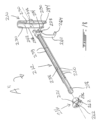
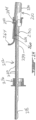
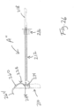
- Figs. 1 to 3 illustrate an anchor assembly A, which is adapted to be mounted to a wall W for use with a fastener (not shown), such as a screw.
- the anchor assembly A comprises a cutting and retention member 10 hereinafter referred to as the toggle member 10, a strap member 12 pivotally connected at pivot 14 to the toggle member 10, and a locking member, such as collar 16.
- the strap member 12 is thus pivotally connected at its rear end to the toggle member 10 and is provided at its front end with a grip member 18.
- the strap member 12, preferably made of plastic, is of substantially semi-circular cross-section and defines a series of ratchet teeth 20 on an outside surface thereof.
- the collar 16 is displaceable along the strap member 12, that is only towards the toggle member 10, the collar 16 including inner locking elements 21 ( Figs. 4 to 6 ) which co-act with the ratchet teeth 20 in order to prevent the collar 16 from being displaced away from the toggle member 10.
- the toggle member 10 defines at a leading, i.e. rear, end thereof a threaded cutting member 22 defining a pointed end and cutting edges 24 for cutting through a friable wall W material when the toggle member 10 is rotated using, for instance, a screwdriver while the toggle member 10 is in its position shown in Fig. 1 , that is in a generally aligned position thereof with respect to the strap member 12.
- the toggle member 10 does not have to be in the aligned position at least during insertion of the threaded cutting member 22 into the wall W, and generally until the forward end of the strap member 12 abuts, or is close to, the visible side of the wall W.
- a proximal, i.e. trailing, end of the toggle member 10 defines a cruciform recess 26 adapted to be engaged by a Phillips-type screwdriver. It is understood that other types of female recesses or even male extensions, engageable respectively by suitable screwdriver bits or by suitable rotatable sockets, could also be used.
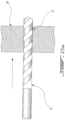
- a spring-loaded tab 28 is provided at the rear, i.e. leading, end of the strap member 12 such as to be engaged by the toggle member 10 when the latter is aligned, as in Fig. 1 , with the strap member 12, such that once the toggle member 10 has been inserted completely through the wall W, the spring-loaded tab 28 biasedly releases the toggle member 10 to its transversal retention position shown in Fig. 2 .
- the toggle member 10 also includes pointed teeth 30 adapted to engage the hidden side of the wall W when the strap member 12 is pulled on.
- the toggle member 10 when it is desired to install the anchor assembly A in the wall W, the toggle member 10 is substantially brought into alignment with the strap member 12, as shown in Fig. 1 . Then, a suitable tool, such as a screwdriver or a power driven screwdriver bit, is engaged in the cruciform recess 26 of the toggle member 10 and is then rotated such that the cutting member 22 of the toggle member 10 defines a hole in the wall W. Once the toggle member 10 has been inserted completely through the wall W, the spring-loaded tab 28 of the strap member 12 swings the toggle member 10 to its transversal position shown in Figs. 2 and 3 , that is generally perpendicular to the strap member 12.
- a suitable tool such as a screwdriver or a power driven screwdriver bit
- the strap member 12 is then pulled away from the wall W, such that the pointed teeth 30 of the toggle member 10 engage the hidden surface of the wall W.
- the collar 16 is then slid towards the wall W along the ratchet teeth 20 of the strap member 12 that is until a skirt 32 of the collar 16 is inserted in the hole defined in the wall W, and a flange 34 of the collar 16 abuts the visible side of the wall W.
- the grip member 18 is held onto by the user while the collar 16 is displaced towards the wall W.
- the collar 16 is slid longitudinally along the strap member 12, and without being able to rotate with respect to the strap member 12 as a result of the non-circular opening 36 defined in the collar 16, which defines shoulders 37 ( Figs. 1 to 3 ) that are engaged by the longitudinal edges 39 of the strap member 12, as best seen in Fig. 1 .
- the grip member 18 and the section of the strap member 12 extending between the grip member 18 and the flange 34 of the collar 16 can be discarded, for instance, by cutting or, as in the present embodiment, by bending as the strap member 12 is provided with weakened areas which allow the strap member 12 to be separated in two. The remaining portion of the strap 12 thus connects the toggle member 10 to the collar 16 within the hole in the wall W.
- a fastener can then be engaged through the central opening 36 defined in the collar 16, within a semi-circular channel 38 defined longitudinally along the strap member 12, and through an opening 40 defined in the toggle member 10.
- the opening 40 in the toggle member 10 may be, for instance, tapped by the fastener such that the fastener becomes firmly secured to the anchor assembly A which itself is firmly secured to the wall W, as explained hereinabove. If the opening 40 is provided with a machine tap, a bolt can be used as the fastener. If the fastener is provided at its head, for instance, with a hook, the anchor assembly A can be used in a ceiling.
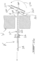
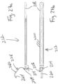
- Figs. 14 to 16 illustrate a variant anchor assembly A', which is similar to the anchor assembly A of Fig. 1 , whereby in the following description and drawings that pertain thereto, components of anchor assembly A' which are identical in function and identical and/or similar in structure to corresponding components of anchor assembly A of Fig. 1 (and Figs. 2 to 13 ) bear the same reference as in Fig. 1 (and Figs. 2 to 13 ), but are tagged with the prefix "1" and are thus in the hundreds with the last two digits thereof being identical to the reference numerals of corresponding components of anchor assembly A. New components (or components not identified for anchor assembly A) provided in anchor assembly A' start at reference numeral 142.
- both anchor assemblies A and A' are very similar, except for their toggle members, as explained hereinbelow.
- the anchor assembly A' is also adapted to be mounted to a wall for use with a fastener (not shown), such as a screw.
- the anchor assembly A' comprises a retention member 110 hereinafter referred to as the toggle member 110, a strap member 112 pivotally connected at pivot 114 to the toggle member 110, and a locking member, such as collar 116.
- the strap member 112 is thus pivotally connected at its rear, leading, end to the toggle member 110 and is provided at its front end with a grip member 118.
- the strap member 112 preferably made of plastic, is of substantially semi-circular cross-section and defines a series of ratchet teeth 120 on an outside surface thereof.
- the collar 116 is displaceable along the strap member 112, that is only towards the toggle member 110, the collar 116 including inner locking elements (not shown) which co-act with the ratchet teeth 120 in order to prevent the collar 116 from being displaced away from the toggle member 110, i.e. from being retracted back towards the grip member 118.
- the toggle member 110 as opposed to the toggle member 10 of the anchor assembly A of Fig. 1 , does not define at a leading end thereof a threaded cutting member. Therefore, in the case of the anchor assembly A', a hole must be formed, e.g. drilled, through the wall before the anchor assembly A' can be mounted thereto, as will be explained in more detail hereinafter.
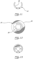
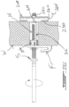
- the toggle member 110 is of C-shaped cross-section such that an open side 142 thereof faces the collar 116, when the toggle member 110 is in the transversal retention position thereof shown in Figs. 14 to 16 .
- a spring-loaded tab 128 is provided at the rear, i.e. leading, end of the strap member 112 such as to be engaged by the toggle member 110 when the latter is aligned with the strap member 112 (this position is generally shown in Fig. 1 with respect to anchor assembly A). Therefore, with the toggle member 110 and the strap member 112 in such a generally aligned insertion position, the toggle member 110 can be inserted through the wall.
- the tab 128 includes a V-shaped tongue 144 that is forcibly folded or collapsed when the toggle member 110 is brought to the insertion position and that causes, as it plastically returns to its at-rest position (see Figs. 14 to 16 ) the toggle member 110 to displace to its transversal retention position.
- Parallel and more importantly co-planar linear edges 146 of the toggle member 110 are adapted to bearably engage the hidden side of the wall when the strap member 112 is pulled on.
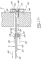
- a hole H is first formed through the wall W, using for instance a drill bit B (see Fig. 17a ).
- the toggle member 110 is then substantially brought into alignment with the strap member 112 (as seen in Figs. 17b ), against the bias of the spring-loaded tab 128, and is inserted completely through the wall W (see Figs.17c and 17d ).
- the spring-loaded tab 128 of the strap member 112 swings the toggle member 110 to its transversal retention position shown in Figs. 14 to16, that is generally perpendicular to the strap member 112.
- the strap member 112 is then pulled away from the wall W, along arrow 148 in Fig. 17e , such that the linear edges 146 of the toggle member 110 engage the hidden surface of the wall W.
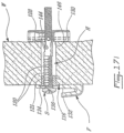
- the collar 116 is then slid, along arrows 150 ( Fig. 17e ) towards the wall W and the toggle member 110, along the ratchet teeth 120 of the strap member 112, that is until a skirt 132 of the collar 116 is inserted in the hole H defined in the wall W and a flange 134 of the collar 116 abuts the visible side of the wall W.
- the grip member 118 is held onto by the user while the collar 116 is displaced towards the wall W.
- the collar 116 is slid longitudinally along the strap member 112, and without being able to rotate with respect to the strap member 112 as a result of the non-circular opening 136 defined in the collar 116, which defines shoulders 137 (see Figs. 14 and 15 ) that are engaged by longitudinal edges 139 of the strap member 112, as best seen in Fig. 15 .
- the grip member 118 and the section of the strap member 112 extending between the grip member 118 and the flange 134 of the collar 116 can be discarded, for instance, by cutting or, as in the present embodiment, by bending (see Fig. 17f ) as the strap member 112 is provided with weakened areas which allow the strap member 112 to be separated in two. As shown in Fig. 17g , the remaining portion of the strap 112 thus connects the toggle member 110 to the collar 116 within the hole H in the wall W.
- a fastener such as a screw or a bolt S
- a fastener can then be engaged through the central opening 136 defined in the collar 116, within a semi-circular channel 138 defined longitudinally along the strap member 112, and through an opening 140 defined in the toggle member 110.
- This opening 140 in the toggle member 110 may be, for instance, tapped by the fastener such that the fastener becomes firmly secured to the anchor assembly A' which itself is firmly secured to the wall W, as explained hereinabove. If the opening 140 defines a machine tap (as in Figs. 17a to 17i ), the bolt S can be used as the fastener.
- the anchor assembly A' can be used in a ceiling.
- the bolt S is used to mount a hook fixture F to the wall W, as seen in Figs. 17g to 17h .
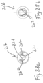
- Figs. 18 to 29b illustrate another variant anchor assembly A", which is similar to the anchor assemblies A and A' of Fig. 1 (and Figs. 2 to 13 ) and Fig. 14 (and Figs. 15 to 17i ), whereby in the following description and drawings that pertain thereto, components of the anchor assembly A" which are identical in function and identical and/or similar in structure to corresponding components of anchor assemblies A and A', but are tagged with the prefix "2" and are thus in the two hundreds with the last two digits thereof being identical to the reference numerals of corresponding components of the anchor assemblies A and A'. New components (or components not identified for either anchor assemblies A and A') provided in the anchor assembly A" start at reference numeral 260.
- the anchor assembly A" of Fig. 18 is more similar to the anchor assembly A' of Fig. 14 than to the anchor assembly A of Fig. 1 .
- the main differences between the anchor assembly A" of Fig. 18 and the anchor assembly A' of Fig. 14 are: (1) the anchor assembly A" has a spring-loaded tab 228 that includes an extended curved tail 260; (2) the pointed teeth 230 of the toggle member 210 of the anchor assembly A" are curved inwardly (as best seen in Figs.
- the collar 216 of the anchor assembly A" has a pair of spring-loaded arms 262, each provided with a locking element 221 adapted to co-act with the ratchet teeth 220 of the strap member 212 to prevent the collar 216 from moving away from the toggle member 210 once the collar 216 has engaged the ratchet teeth 220 of the strap member 212.
- the anchor assembly A" is also adapted to be mounted to a wall for use with a fastener, such as a screw S shown in Fig. 25i .
- the anchor assembly A" mainly comprises a retention member 210 hereinafter referred to as the toggle member 210, the strap member 212 pivotally connected at pivot 214 to the toggle member 210, and a locking member, such as the collar 216.
- the strap member 212 is thus pivotally connected at its rear, leading, end to the toggle member 210 and is provided at its front end with a grip member 218.
- the strap member 212 preferably made of plastic, is of substantially semi-circular cross-section and defines a series of ratchet teeth 220 on an outside surface thereof.
- the collar 216 is displaceable along the strap member 212, that is only towards the toggle member 210, in that the collar 216 for instance includes the inner locking elements 221 (part of the pair of spring-loaded arms 262), which co-act with the ratchet teeth 220 in order to prevent the collar 216 from being displaced away from the toggle member 210, i.e. from being retracted back towards the grip member 218.
- the toggle member 210 as opposed to the toggle member 10 of the anchor assembly A of Fig. 1 , herein does not define at a leading end thereof a threaded cutting member, but it could. Therefore, in the case of the anchor assembly A", a hole must be formed, e.g. drilled, through the wall before the anchor assembly A" can be mounted thereto, as will be explained in more detail hereinafter.
- the toggle member 210 is of C-shaped cross-section such that an open side 242 thereof faces the collar 216, when the toggle member 210 is in the transversal retention position thereof shown in Figs. 18 to 22 .
- the spring-loaded tab 228 is provided at the rear, i.e. leading, end of the strap member 212 such as to be engaged by the toggle member 210 when the latter is aligned with the strap member 212 (this position is shown in Figs. 23 , 24 and 25c ). Therefore, with the toggle member 210 and the strap member 212 in such a generally aligned insertion position, the toggle member 210 can be inserted through the wall.
- the spring-loaded tab 228 is in a biased state.
- the toggle member 210 is retained to the strap member 212 by way of the inwardly curved pointed teeth 230 of the toggle member 210, which grasp the longitudinal edges 239 of the strap member 212 and so retain the toggle member 210 and the strap member 212 engaged together (in the aligned insertion position), and against the spring force of the spring-loaded tab 228 that is in a collapsed position.
- the extended curved tail 260 of the spring-loaded tab 228 extends past one of the longitudinal ends of the toggle member 210 and is, along with its spring-loaded tab 228, biased in a collapsed position.
- a curved free end 264 of the tail 260 extends outwardly away from the strap member 212, as well seen in Fig. 24 .
- the anchor assembly A" is pulled away from the wall such that the free end 264 engages the hidden side of the wall, causing the curved tail 260 to pull on the toggle member 210, thereby releasing the toggle member 210 from the strap member 212.
- the toggle member 210 then spring backs so as to assume its transversal retention position shown in Figs. 18 to 22 . This will become more apparent when described hereinbelow with reference to installation Figs. 25a to 25i .
- the tab 228 includes a V-shaped tongue 244 that is forcibly folded or collapsed when the toggle member 210 is brought to the insertion position and that causes, as it plastically returns to its at-rest position (of Figs. 18 to 22 ) the toggle member 210 to displace to its transversal retention position.
- Parallel and co-planar edges 246 of the toggle member 210 are adapted to bearably engage the hidden side of the wall when the strap member 212 is pulled on.
- the pointed teeth 230 of the toggle member 210 are then adapted to penetrate the hidden side of the wall.
- a hole H is first formed through the wall W, using for instance a drill bit B (see Fig. 25a ).
- the toggle member 210 is then pivoted along arrow 266 and substantially brought into alignment with the strap member 212 (as seen in Figs. 25b ), against the bias of the spring-loaded tab 228 (and its V-shaped tongue 244), until the pointed teeth 230 of the toggle member 210 engage the longitudinal edges 239 of the strap member 212 and so connect together the toggle member 210 and the strap member 212 (in the aligned insertion position).
- the toggle member 210 is inserted along arrow 268 completely through the wall W.
- the strap member 212 is then pulled away from the wall W such that the linear edges 246 of the toggle member 210 engage the hidden surface of the wall W (or this may result when the collar 216 is moved towards the wall W, as described hereinafter).
- the collar 216 is then slid, along arrows 274 ( Fig. 25f ) towards the wall W and the toggle member 210, along the ratchet teeth 220 of the strap member 212, that is until a skirt 232 of the collar 216 is inserted in the hole H defined in the wall W and a flange 234 of the collar 216 abuts the visible side of the wall W.
- the grip member 218 is held onto by the user while the collar 216 is displaced towards the wall W, and may be pulled along arrow 276 if the toggle member 210 is not yet in abutting engagement with the hidden surface of the wall W, which is the case illustrated in Fig. 25f .
- the collar 216 is slid longitudinally along the strap member 212 until it assumes the position shown in Fig. 25g and the toggle member 210 is in contact with the hidden surface of the wall W.
- the grip member 218 and the section of the strap member 212 extending between the grip member 218 and the flange 234 of the collar 216 can be discarded, for instance, by cutting or, as in the present embodiment, by bending (see Fig. 25h ) as the strap member 212 is provided with weakened areas which allow the strap member 212 to be separated in two. As also shown in Fig. 25h (and in Fig. 25i ), the remaining portion of the strap 212 thus connects the toggle member 210 to the collar 216 within the hole H in the wall W.
- a fastener such as a screw or a bolt S
- a fastener can then be engaged through the central opening 236 defined in the collar 216, within a semi-circular channel 238 defined longitudinally along the strap member 212, and through an opening 240 defined in the toggle member 210.
- This opening 240 in the toggle member 210 may be, for instance, tapped by the fastener such that the fastener becomes firmly secured to the anchor assembly A" which itself is firmly secured to the wall W, as explained hereinabove.
- the opening 240 defines a machine tap or thread as herein (see Fig. 21 )
- the bolt S can be used as the fastener.
- the fastener is provided at its head, for instance, with a hook
- the anchor assembly A" can be used in a ceiling.
- the bolt S is used to mount a hook fixture F to the wall W, as seen in Fig. 25i .
Abstract
Description
- The present subject-matter relates to wall anchors and, more particularly, to a wall anchor for use typically in hollow walls, such as those made of friable materials, e.g. gypsum.
-
U.S. Patent No. 4,294,156 issued on October 13, 1981 to McSherry et al. discloses an anchor assembly for retaining an elongated fastener within an opening defined in a wall. The anchor assembly includes a channel member acting as a toggle, and a pair of straps extending from the channel member and being pivotally mounted thereto. A pulling ring is provided at the ends of the straps opposite their ends connected to the channel member. A collar is engaged around the two straps and can be displaced, ratchet-type, towards the channel member. A hole is first defined through the wall and the channel member, oriented parallel to the straps is inserted through the hole such as to extend behind the wall, the channel member adopting once having passed the opening in the wall an orientation generally perpendicular to the straps and lying against the hidden surface of the wall after the straps have been pulled on via the pulling ring. The collar is then displaced along the straps and towards the wall until it firmly abuts the visible surface of the wall, the wall being imprisoned between the channel member and the collar which are connected by the straps. The pulling ring and the sections of the straps which extend forwardly of the collar can then be cut and a fastener can then be engaged through the collar and through a threaded opening defined in the channel member thereby allowing the fastener to be secured to the wall and to hold an article thereto. -
U.S. Patents No. 4,075,924 issued on February 28, 1978 and No.4,650,386 issued on March 17,1987, both to McSherry et al. , are also of interest. - It would thus be desirable to provide a novel anchor assembly typically for use with a fastener in hollow walls.
- The embodiments described herein provide in one aspect an anchor assembly for walls, comprising a strap member, a spring member, a toggle member pivotally mounted to said strap member, and a locking member slidable along said strap member, said toggle member being displaceable between first and second positions thereof, wherein in said first position said toggle member is substantially aligned with said strap member for insertion through a hole in the wall while biasedly engaging said spring member, wherein in the first position the toggle member is engaged to the strap member, wherein said toggle member once behind the wall is adapted to be displaced towards said second position by said spring member, and wherein in said second position said toggle member extends behind the wall at an angle relative to said strap member with said strap member extending from said toggle member through the hole in the wall, said locking member being adapted to be displaced along said strap member and towards the wall and said toggle member, whereby once the anchor assembly is installed, said locking member and said toggle member are connected by a distal section of said strap member and imprison the wall by abutting opposed sides thereof, said toggle member being adapted to be engaged by a fastener introduced through said locking member and through the hole in the wall.
- For a better understanding of the embodiments described herein and to show more clearly how they may be carried into effect, reference will now be made, by way of example only, to the accompanying drawings, which show at least one exemplary embodiment, and in which:
-
Fig. 1 is a perspective view of an anchor assembly in accordance with a first exemplary embodiment, and showing a toggle member of the anchor assembly in a first insertion position thereof, a wall being schematically shown in phantom lines; -
Fig. 2 is an exploded perspective view of the anchor assembly ofFig. 1 , and showing the toggle member in a second retention position thereof; -
Fig. 3 is a perspective view of the anchor assembly ofFig. 1 with the toggle member shown in the second position thereof; -
Figs. 4 and 5 are top plan views of the anchor assembly ofFig. 1 with the toggle member shown respectively in the first and second positions thereof; -
Figs. 6 and 7 are respectively side elevational and rear elevational views of the anchor assembly ofFig. 5 ; -
Figs. 8 to 13 are various views of a toggle member, a strap member and a locking member of the anchor assembly; -
Fig. 14 is an exploded perspective view of an anchor assembly in accordance with a second an exemplary embodiment, and showing a toggle member of the anchor assembly in a retention position thereof; -
Fig. 15 is a perspective view of the anchor assembly ofFig. 14 , and with the toggle member shown in the retention position thereof; -
Fig. 16 is a further perspective view of the anchor assembly ofFig. 14 and with the toggle member shown in the second position thereof; -
Figs. 17a to 17i are successive partly cross-sectional schematic side views showing the installation of the anchor assembly ofFigs. 14 to 16 into a wall; -
Fig. 18 is an exploded perspective view of an anchor assembly in accordance with a third exemplary embodiment, and showing a toggle member of the anchor assembly in a retention position thereof; -
Fig. 19 is a further exploded perspective view of the anchor assembly ofFig. 18 , and with the toggle member shown in the retention position thereof; -
Figs. 20 to 22 are various perspective views of the anchor assembly ofFig. 18 , and with the toggle member shown in the retention position thereof; -
Fig. 23 is a perspective view of the anchor assembly ofFig. 18 and with the toggle member shown in an insertion position thereof; -
Fig. 24 is a longitudinal cross-sectional view taken along line 24-24 ofFig. 23 , showing the anchor assembly ofFig. 23 with the toggle member shown in the insertion position thereof; -
Figs. 25a to 25i are successive partly cross-sectional schematic side views showing the installation of the anchor assembly ofFigs. 18 to 24 into a wall; -
Fig. 26 is a side view of the anchor assembly ofFig. 18 and with the toggle member shown in an at-rest, i.e. retention, position thereof, and with the toggle member and collar being shown transparent for illustrating purposes such as to detail interactions thereof with the strap member; -
Figs. 27a and 27b are side and bottom plan views, respectively, of the strap member of the anchor assembly ofFig. 18 ; -
Figs. 28a and 28b are front and rear views, respectively, of the collar of the anchor assembly ofFig. 18 ; and -
Figs. 29a and 29b are front and top plan views, respectively, of the toggle member of the anchor assembly ofFig. 18 . -
Figs. 1 to 3 illustrate an anchor assembly A, which is adapted to be mounted to a wall W for use with a fastener (not shown), such as a screw. The anchor assembly A comprises a cutting andretention member 10 hereinafter referred to as thetoggle member 10, astrap member 12 pivotally connected atpivot 14 to thetoggle member 10, and a locking member, such ascollar 16. Thestrap member 12 is thus pivotally connected at its rear end to thetoggle member 10 and is provided at its front end with agrip member 18. Thestrap member 12, preferably made of plastic, is of substantially semi-circular cross-section and defines a series ofratchet teeth 20 on an outside surface thereof. Thecollar 16 is displaceable along thestrap member 12, that is only towards thetoggle member 10, thecollar 16 including inner locking elements 21 (Figs. 4 to 6 ) which co-act with theratchet teeth 20 in order to prevent thecollar 16 from being displaced away from thetoggle member 10. - The
toggle member 10 defines at a leading, i.e. rear, end thereof a threadedcutting member 22 defining a pointed end and cuttingedges 24 for cutting through a friable wall W material when thetoggle member 10 is rotated using, for instance, a screwdriver while thetoggle member 10 is in its position shown inFig. 1 , that is in a generally aligned position thereof with respect to thestrap member 12. In fact, thetoggle member 10 does not have to be in the aligned position at least during insertion of the threadedcutting member 22 into the wall W, and generally until the forward end of thestrap member 12 abuts, or is close to, the visible side of the wall W. - Accordingly, a proximal, i.e. trailing, end of the
toggle member 10 defines acruciform recess 26 adapted to be engaged by a Phillips-type screwdriver. It is understood that other types of female recesses or even male extensions, engageable respectively by suitable screwdriver bits or by suitable rotatable sockets, could also be used. - A spring-loaded
tab 28 is provided at the rear, i.e. leading, end of thestrap member 12 such as to be engaged by thetoggle member 10 when the latter is aligned, as inFig. 1 , with thestrap member 12, such that once thetoggle member 10 has been inserted completely through the wall W, the spring-loadedtab 28 biasedly releases thetoggle member 10 to its transversal retention position shown inFig. 2 . Thetoggle member 10 also includespointed teeth 30 adapted to engage the hidden side of the wall W when thestrap member 12 is pulled on. - Accordingly, when it is desired to install the anchor assembly A in the wall W, the
toggle member 10 is substantially brought into alignment with thestrap member 12, as shown inFig. 1 . Then, a suitable tool, such as a screwdriver or a power driven screwdriver bit, is engaged in thecruciform recess 26 of thetoggle member 10 and is then rotated such that thecutting member 22 of thetoggle member 10 defines a hole in the wall W. Once thetoggle member 10 has been inserted completely through the wall W, the spring-loadedtab 28 of thestrap member 12 swings thetoggle member 10 to its transversal position shown inFigs. 2 and3 , that is generally perpendicular to thestrap member 12. - The
strap member 12 is then pulled away from the wall W, such that thepointed teeth 30 of thetoggle member 10 engage the hidden surface of the wall W. Thecollar 16 is then slid towards the wall W along theratchet teeth 20 of thestrap member 12 that is until askirt 32 of thecollar 16 is inserted in the hole defined in the wall W, and aflange 34 of thecollar 16 abuts the visible side of the wall W. Thegrip member 18 is held onto by the user while thecollar 16 is displaced towards the wall W. Thecollar 16 is slid longitudinally along thestrap member 12, and without being able to rotate with respect to thestrap member 12 as a result of thenon-circular opening 36 defined in thecollar 16, which defines shoulders 37 (Figs. 1 to 3 ) that are engaged by thelongitudinal edges 39 of thestrap member 12, as best seen inFig. 1 . - Once the wall W is firmly imprisoned between the
toggle member 10 and thecollar 16, thegrip member 18 and the section of thestrap member 12 extending between thegrip member 18 and theflange 34 of thecollar 16, can be discarded, for instance, by cutting or, as in the present embodiment, by bending as thestrap member 12 is provided with weakened areas which allow thestrap member 12 to be separated in two. The remaining portion of thestrap 12 thus connects thetoggle member 10 to thecollar 16 within the hole in the wall W. - A fastener can then be engaged through the
central opening 36 defined in thecollar 16, within asemi-circular channel 38 defined longitudinally along thestrap member 12, and through anopening 40 defined in thetoggle member 10. The opening 40 in thetoggle member 10 may be, for instance, tapped by the fastener such that the fastener becomes firmly secured to the anchor assembly A which itself is firmly secured to the wall W, as explained hereinabove. If the opening 40 is provided with a machine tap, a bolt can be used as the fastener. If the fastener is provided at its head, for instance, with a hook, the anchor assembly A can be used in a ceiling. -
Figs. 14 to 16 illustrate a variant anchor assembly A', which is similar to the anchor assembly A ofFig. 1 , whereby in the following description and drawings that pertain thereto, components of anchor assembly A' which are identical in function and identical and/or similar in structure to corresponding components of anchor assembly A ofFig. 1 (andFigs. 2 to 13 ) bear the same reference as inFig. 1 (andFigs. 2 to 13 ), but are tagged with the prefix "1" and are thus in the hundreds with the last two digits thereof being identical to the reference numerals of corresponding components of anchor assembly A. New components (or components not identified for anchor assembly A) provided in anchor assembly A' start atreference numeral 142. - Generally, both anchor assemblies A and A' are very similar, except for their toggle members, as explained hereinbelow. The anchor assembly A' is also adapted to be mounted to a wall for use with a fastener (not shown), such as a screw. The anchor assembly A' comprises a
retention member 110 hereinafter referred to as thetoggle member 110, astrap member 112 pivotally connected atpivot 114 to thetoggle member 110, and a locking member, such ascollar 116. Thestrap member 112 is thus pivotally connected at its rear, leading, end to thetoggle member 110 and is provided at its front end with agrip member 118. - The
strap member 112, preferably made of plastic, is of substantially semi-circular cross-section and defines a series ofratchet teeth 120 on an outside surface thereof. Thecollar 116 is displaceable along thestrap member 112, that is only towards thetoggle member 110, thecollar 116 including inner locking elements (not shown) which co-act with theratchet teeth 120 in order to prevent thecollar 116 from being displaced away from thetoggle member 110, i.e. from being retracted back towards thegrip member 118. - The
toggle member 110, as opposed to thetoggle member 10 of the anchor assembly A ofFig. 1 , does not define at a leading end thereof a threaded cutting member. Therefore, in the case of the anchor assembly A', a hole must be formed, e.g. drilled, through the wall before the anchor assembly A' can be mounted thereto, as will be explained in more detail hereinafter. Thetoggle member 110 is of C-shaped cross-section such that anopen side 142 thereof faces thecollar 116, when thetoggle member 110 is in the transversal retention position thereof shown inFigs. 14 to 16 . - A spring-loaded
tab 128 is provided at the rear, i.e. leading, end of thestrap member 112 such as to be engaged by thetoggle member 110 when the latter is aligned with the strap member 112 (this position is generally shown inFig. 1 with respect to anchor assembly A). Therefore, with thetoggle member 110 and thestrap member 112 in such a generally aligned insertion position, thetoggle member 110 can be inserted through the wall. - Once the
toggle member 110 has been introduced completely past the hidden surface of the wall, the spring-loadedtab 128 biasedly releases thetoggle member 110 to its transversal retention position shown inFigs. 14 to 16 . Thetab 128 includes a V-shapedtongue 144 that is forcibly folded or collapsed when thetoggle member 110 is brought to the insertion position and that causes, as it plastically returns to its at-rest position (seeFigs. 14 to 16 ) thetoggle member 110 to displace to its transversal retention position. Parallel and more importantly co-planarlinear edges 146 of thetoggle member 110 are adapted to bearably engage the hidden side of the wall when thestrap member 112 is pulled on. - Accordingly, with reference to
Figs. 17a to 17i , when it is desired to install the anchor assembly A' in the wall W, a hole H is first formed through the wall W, using for instance a drill bit B (seeFig. 17a ). Thetoggle member 110 is then substantially brought into alignment with the strap member 112 (as seen inFigs. 17b ), against the bias of the spring-loadedtab 128, and is inserted completely through the wall W (seeFigs.17c and17d ). InFig. 17d , the spring-loadedtab 128 of thestrap member 112 swings thetoggle member 110 to its transversal retention position shown inFigs. 14 to16, that is generally perpendicular to thestrap member 112. - The
strap member 112 is then pulled away from the wall W, alongarrow 148 inFig. 17e , such that thelinear edges 146 of thetoggle member 110 engage the hidden surface of the wall W. Thecollar 116 is then slid, along arrows 150 (Fig. 17e ) towards the wall W and thetoggle member 110, along theratchet teeth 120 of thestrap member 112, that is until askirt 132 of thecollar 116 is inserted in the hole H defined in the wall W and aflange 134 of thecollar 116 abuts the visible side of the wall W. Thegrip member 118 is held onto by the user while thecollar 116 is displaced towards the wall W. Thecollar 116 is slid longitudinally along thestrap member 112, and without being able to rotate with respect to thestrap member 112 as a result of thenon-circular opening 136 defined in thecollar 116, which defines shoulders 137 (seeFigs. 14 and15 ) that are engaged bylongitudinal edges 139 of thestrap member 112, as best seen inFig. 15 . - Once the wall W is firmly imprisoned between the
toggle member 110 and thecollar 116, thegrip member 118 and the section of thestrap member 112 extending between thegrip member 118 and theflange 134 of thecollar 116, can be discarded, for instance, by cutting or, as in the present embodiment, by bending (seeFig. 17f ) as thestrap member 112 is provided with weakened areas which allow thestrap member 112 to be separated in two. As shown inFig. 17g , the remaining portion of thestrap 112 thus connects thetoggle member 110 to thecollar 116 within the hole H in the wall W. - Still referring to
Fig. 17g , a fastener, such as a screw or a bolt S, can then be engaged through thecentral opening 136 defined in thecollar 116, within asemi-circular channel 138 defined longitudinally along thestrap member 112, and through anopening 140 defined in thetoggle member 110. Thisopening 140 in thetoggle member 110 may be, for instance, tapped by the fastener such that the fastener becomes firmly secured to the anchor assembly A' which itself is firmly secured to the wall W, as explained hereinabove. If theopening 140 defines a machine tap (as inFigs. 17a to 17i ), the bolt S can be used as the fastener. If the fastener is provided at its head, for instance, with a hook, the anchor assembly A' can be used in a ceiling. Here, the bolt S is used to mount a hook fixture F to the wall W, as seen inFigs. 17g to 17h . - Furthermore,
Figs. 18 to 29b illustrate another variant anchor assembly A", which is similar to the anchor assemblies A and A' ofFig. 1 (andFigs. 2 to 13 ) andFig. 14 (andFigs. 15 to 17i ), whereby in the following description and drawings that pertain thereto, components of the anchor assembly A" which are identical in function and identical and/or similar in structure to corresponding components of anchor assemblies A and A', but are tagged with the prefix "2" and are thus in the two hundreds with the last two digits thereof being identical to the reference numerals of corresponding components of the anchor assemblies A and A'. New components (or components not identified for either anchor assemblies A and A') provided in the anchor assembly A" start atreference numeral 260. - Generally, the anchor assembly A" of
Fig. 18 is more similar to the anchor assembly A' ofFig. 14 than to the anchor assembly A ofFig. 1 . The main differences between the anchor assembly A" ofFig. 18 and the anchor assembly A' ofFig. 14 are: (1) the anchor assembly A" has a spring-loadedtab 228 that includes an extendedcurved tail 260; (2) the pointedteeth 230 of thetoggle member 210 of the anchor assembly A" are curved inwardly (as best seen inFigs. 29a and 29b ); and (3) thecollar 216 of the anchor assembly A" has a pair of spring-loadedarms 262, each provided with alocking element 221 adapted to co-act with theratchet teeth 220 of thestrap member 212 to prevent thecollar 216 from moving away from thetoggle member 210 once thecollar 216 has engaged theratchet teeth 220 of thestrap member 212. We will now provide additional details on the foregoing. - The anchor assembly A" is also adapted to be mounted to a wall for use with a fastener, such as a screw S shown in
Fig. 25i . The anchor assembly A" mainly comprises aretention member 210 hereinafter referred to as thetoggle member 210, thestrap member 212 pivotally connected atpivot 214 to thetoggle member 210, and a locking member, such as thecollar 216. Thestrap member 212 is thus pivotally connected at its rear, leading, end to thetoggle member 210 and is provided at its front end with agrip member 218. - The
strap member 212, preferably made of plastic, is of substantially semi-circular cross-section and defines a series ofratchet teeth 220 on an outside surface thereof. Thecollar 216 is displaceable along thestrap member 212, that is only towards thetoggle member 210, in that thecollar 216 for instance includes the inner locking elements 221 (part of the pair of spring-loaded arms 262), which co-act with theratchet teeth 220 in order to prevent thecollar 216 from being displaced away from thetoggle member 210, i.e. from being retracted back towards thegrip member 218. - The
toggle member 210, as opposed to thetoggle member 10 of the anchor assembly A ofFig. 1 , herein does not define at a leading end thereof a threaded cutting member, but it could. Therefore, in the case of the anchor assembly A", a hole must be formed, e.g. drilled, through the wall before the anchor assembly A" can be mounted thereto, as will be explained in more detail hereinafter. Thetoggle member 210 is of C-shaped cross-section such that anopen side 242 thereof faces thecollar 216, when thetoggle member 210 is in the transversal retention position thereof shown inFigs. 18 to 22 . - The spring-loaded
tab 228 is provided at the rear, i.e. leading, end of thestrap member 212 such as to be engaged by thetoggle member 210 when the latter is aligned with the strap member 212 (this position is shown inFigs. 23 ,24 and25c ). Therefore, with thetoggle member 210 and thestrap member 212 in such a generally aligned insertion position, thetoggle member 210 can be inserted through the wall. - In this insertion position, the spring-loaded
tab 228 is in a biased state. Also, in this insertion position, thetoggle member 210 is retained to thestrap member 212 by way of the inwardly curved pointedteeth 230 of thetoggle member 210, which grasp thelongitudinal edges 239 of thestrap member 212 and so retain thetoggle member 210 and thestrap member 212 engaged together (in the aligned insertion position), and against the spring force of the spring-loadedtab 228 that is in a collapsed position. - Again in the insertion position, the extended
curved tail 260 of the spring-loadedtab 228 extends past one of the longitudinal ends of thetoggle member 210 and is, along with its spring-loadedtab 228, biased in a collapsed position. A curvedfree end 264 of thetail 260 extends outwardly away from thestrap member 212, as well seen inFig. 24 . - Generally, once the
toggle member 210 has been introduced completely past the hidden surface of the wall, the anchor assembly A" is pulled away from the wall such that thefree end 264 engages the hidden side of the wall, causing thecurved tail 260 to pull on thetoggle member 210, thereby releasing thetoggle member 210 from thestrap member 212. Thetoggle member 210 then spring backs so as to assume its transversal retention position shown inFigs. 18 to 22 . This will become more apparent when described hereinbelow with reference to installationFigs. 25a to 25i . - As for anchor assembly A', the
tab 228 includes a V-shapedtongue 244 that is forcibly folded or collapsed when thetoggle member 210 is brought to the insertion position and that causes, as it plastically returns to its at-rest position (ofFigs. 18 to 22 ) thetoggle member 210 to displace to its transversal retention position. Parallel andco-planar edges 246 of thetoggle member 210 are adapted to bearably engage the hidden side of the wall when thestrap member 212 is pulled on. The pointedteeth 230 of thetoggle member 210 are then adapted to penetrate the hidden side of the wall. - Accordingly, with reference to
Figs. 25a to 25i , when it is desired to install the anchor assembly A" in the wall W, a hole H is first formed through the wall W, using for instance a drill bit B (seeFig. 25a ). As seen fromFig. 25b to Fig. 25c , thetoggle member 210 is then pivoted alongarrow 266 and substantially brought into alignment with the strap member 212 (as seen inFigs. 25b ), against the bias of the spring-loaded tab 228 (and its V-shaped tongue 244), until the pointedteeth 230 of thetoggle member 210 engage thelongitudinal edges 239 of thestrap member 212 and so connect together thetoggle member 210 and the strap member 212 (in the aligned insertion position). - As per
Figs. 25c and25d , thetoggle member 210 is inserted alongarrow 268 completely through the wall W. - In
Fig. 25d , once thetoggle member 210 has been introduced completely past the hidden surface of the wall W, the anchor assembly A" is pulled away from the wall W, alongarrow 270, such that thefree end 264 of thecurved tail 260 engages the hidden side of the wall W, causing thecurved tail 260 to pull on thetoggle member 210, thereby releasing thetoggle member 210 from thestrap member 212, as shown inFig. 25e . Under the spring force of the spring-loadedtab 128 of thestrap member 112, thetoggle member 210 then spring backs, alongarrow 272, to its transversal retention position shown inFigs. 18 to 22 and also inFig. 25f , which is generally perpendicular to thestrap member 212. - The
strap member 212 is then pulled away from the wall W such that thelinear edges 246 of thetoggle member 210 engage the hidden surface of the wall W (or this may result when thecollar 216 is moved towards the wall W, as described hereinafter). Thecollar 216 is then slid, along arrows 274 (Fig. 25f ) towards the wall W and thetoggle member 210, along theratchet teeth 220 of thestrap member 212, that is until askirt 232 of thecollar 216 is inserted in the hole H defined in the wall W and a flange 234 of thecollar 216 abuts the visible side of the wall W. Thegrip member 218 is held onto by the user while thecollar 216 is displaced towards the wall W, and may be pulled alongarrow 276 if thetoggle member 210 is not yet in abutting engagement with the hidden surface of the wall W, which is the case illustrated inFig. 25f . Thecollar 216 is slid longitudinally along thestrap member 212 until it assumes the position shown inFig. 25g and thetoggle member 210 is in contact with the hidden surface of the wall W. - Once the wall W is firmly imprisoned between the
toggle member 210 and thecollar 216, thegrip member 218 and the section of thestrap member 212 extending between thegrip member 218 and the flange 234 of thecollar 216, can be discarded, for instance, by cutting or, as in the present embodiment, by bending (seeFig. 25h ) as thestrap member 212 is provided with weakened areas which allow thestrap member 212 to be separated in two. As also shown inFig. 25h (and inFig. 25i ), the remaining portion of thestrap 212 thus connects thetoggle member 210 to thecollar 216 within the hole H in the wall W. - Now referring to
Fig. 25i , a fastener, such as a screw or a bolt S, can then be engaged through thecentral opening 236 defined in thecollar 216, within asemi-circular channel 238 defined longitudinally along thestrap member 212, and through anopening 240 defined in thetoggle member 210. Thisopening 240 in thetoggle member 210 may be, for instance, tapped by the fastener such that the fastener becomes firmly secured to the anchor assembly A" which itself is firmly secured to the wall W, as explained hereinabove. If theopening 240 defines a machine tap or thread as herein (seeFig. 21 ), the bolt S can be used as the fastener. If the fastener is provided at its head, for instance, with a hook, the anchor assembly A" can be used in a ceiling. Here, the bolt S is used to mount a hook fixture F to the wall W, as seen inFig. 25i . - The steps shown in
Fig. 25c to Fig. 25e can thus conveniently be achieved using a single hand. - While the above description provides examples of the embodiments, it will be appreciated that some features and/or functions of the described embodiments are susceptible to modification without departing from the spirit and principles of operation of the described embodiments. Accordingly, what has been described above has been intended to be illustrative of the embodiments and non-limiting, and it will be understood by persons skilled in the art that other variants and modifications may be made without departing from the scope of the embodiments as defined in the claims appended hereto.
-
- 1. An anchor assembly for walls, comprising a strap member, a spring member, a toggle member pivotally mounted to said strap member, and a locking member slidable along said strap member, said toggle member being displaceable between first and second positions thereof, wherein in said first position said toggle member is substantially aligned with said strap member for insertion through a hole in the wall while biasedly engaging said spring member, wherein in the first position the toggle member is engaged to the strap member, wherein said toggle member once behind the wall is adapted to be displaced towards said second position by said spring member, and wherein in said second position said toggle member extends behind the wall at an angle relative to said strap member with said strap member extending from said toggle member through the hole in the wall, said locking member being adapted to be displaced along said strap member and towards the wall and said toggle member, whereby once the anchor assembly is installed, said locking member and said toggle member are connected by a distal section of said strap member and imprison the wall by abutting opposed sides thereof, said toggle member being adapted to be engaged by a fastener introduced through said locking member and through the hole in the wall.
- 2. An anchor assembly as defined in example 1, wherein a proximal section of said strap member located forwardly of said locking member is adapted to be removed once the anchor assembly is installed and the locking member abuts the wall.
- 3. An anchor assembly as defined in any one of examples 1 and 2, wherein locking means are provided for preventing said locking member from being displaced away from said toggle member, once the anchor assembly is installed.
- 4. An anchor assembly as defined in any one of examples 1 to 3, wherein said spring member includes an extended free end, which is adapted to release the toggle member from the strap member and thereby allow the toggle member to displace from the first to the second positions.
- 5. An anchor assembly as defined in example 4, wherein the extended free end is curved and is adapted to disengage the toggle member from the strap member by pulling on the anchor assembly such that the free end engages a hidden side of the wall.
- 6. An anchor assembly as defined in any one of examples 1 to 5, wherein, in the first position, the toggle member is engaged to the strap member by way of hooks provided on the toggle member and adapted to releasingly engage the strap member.
- 7. An anchor assembly as defined in example 6, wherein the hooks include grasping teeth that extend inwardly from edges of the toggle member.
- 8. An anchor assembly as defined in example 7, wherein the toggle member is hollow such as to accommodate therein part of the strap member, in the first position.
- 9. An anchor assembly as defined in any one of examples 6 to 7, wherein the grasping teeth are at least one of pointed and curved.
- 10. An anchor assembly as defined in any one of examples 6 to 9, wherein in the first position, the spring member extends between the toggle member and the strap member.
- 11. An anchor assembly as defined in example 10, wherein the extended free end of the spring member extends past the toggle member, in the first position.
Claims (15)
- An anchor assembly (A") for walls (W), comprising a strap member (212), a spring member (228), and a toggle member (210) pivotally mounted to said strap member (212), said toggle member (210) being displaceable between first and second positions thereof, wherein in said first position said toggle member (210) is substantially aligned with said strap member (212) for insertion through a hole (H) in the wall (W) while biasedly engaging said spring member (228), wherein in the first position the toggle member (210) is engaged to the strap member (212), wherein said toggle member (210) once behind the wall (W) is adapted to be displaced towards said second position by said spring member (228), and wherein in said second position said toggle member (210) extends behind the wall (W) at an angle relative to said strap member (212) with said strap member (212) extending from said toggle member (210) through the hole (H) in the wall (W), said toggle member (210) when in said second position being adapted to be engaged by a fastener (S) introduced through the hole (H) in the wall (W).
- The anchor assembly (A") as defined in Claim 1, wherein said spring member (228) includes an extended free end (260), which is adapted to release the toggle member (210) from the strap member (212) and thereby allow the toggle member (210) to displace from the first to the second positions.
- The anchor assembly (A") as defined in Claim 2, wherein the extended free end (260) is curved (264) and is adapted to disengage the toggle member (210) from the strap member (212) when the anchor assembly is pulled such that the free end (260) engages a hidden side of the wall (W).
- The anchor assembly (A") as defined in any one of Claims 1 to 3, wherein, in the first position, the toggle member (210) is engaged to the strap member (212) by way of at least one hook provided on the toggle member (210) and adapted to releasingly engage the strap member (212).
- The anchor assembly (A") as defined in Claim 4, wherein the hook (230) includes grasping teeth (230) that extend inwardly from edges (246) of the toggle member (210).
- The anchor assembly (A") as defined in Claim 5, wherein the toggle member (210) is hollow (242) such as to accommodate therein part of the strap member (212), in the first position.
- The anchor assembly (A") as defined in any one of Claims 4 to 5, wherein the grasping teeth (230) are at least one of pointed and curved.
- The anchor assembly (A") as defined in any one of Claims 4 to 7, wherein in the first position, the spring member (228) extends between the toggle member (210) and the strap member (212).
- The anchor assembly (A") as defined in any one of Claims 2 to 8, wherein the extended free end (260) of the spring member (228) extends past the toggle member (210), in the first position.
- An anchor assembly (A") for walls (W), comprising a strap member (212), a spring member (228), and a toggle member (210) pivotally mounted to said strap member (212), said toggle member (210) being displaceable between first and second positions thereof, wherein in said first position said toggle member (210) is substantially aligned with said strap member (212) for insertion through a hole (H) in the wall (W) while biasedly engaging said spring member (228), wherein in the first position the toggle member (210) is engaged to the strap member (212), wherein said toggle member (210) once behind the wall (W) is adapted to be released from the strap member (212) and to displace towards said second position by said spring member (228), and wherein in said second position said toggle member (210) extends behind the wall (W) at an angle relative to said strap member (212) with said strap member (212) extending from said toggle member (210) through the hole (H) in the wall (W), said toggle member (210) when in said second position being adapted to be engaged by a fastener (S) introduced through the hole (H) in the wall (W).
- The anchor assembly (A") as defined in Claim 10, wherein said spring member (228) includes an extended free end (260), which is adapted to release the toggle member (210) from the strap member (212) and thereby allow the toggle member (210) to displace from the first to the second positions.
- The anchor assembly (A") as defined in Claim 11, wherein the extended free end (260) is curved (264) and is adapted to disengage the toggle member (210) from the strap member (212) when the anchor assembly is pulled such that the free end (260) engages a hidden side of the wall (W).
- The anchor assembly (A") as defined in any one of Claims 10 to 12, wherein, in the first position, the toggle member (210) is engaged to the strap member (212) by way of at least one hook provided on the toggle member (210) and adapted to releasingly engage the strap member (212).
- The anchor assembly (A") as defined in Claim 13, wherein the hook includes grasping teeth (230) that extend inwardly from edges (246) of the toggle member (210), and wherein the grasping teeth (230) are at least one of pointed and curved.
- The anchor assembly (A") as defined in any one of Claims 10 to 14, wherein in the first position, the spring member (228) extends between the toggle member (210) and the strap member (212), and wherein the extended free end (260) of the spring member (228) extends past the toggle member (210), in the first position.
Priority Applications (1)
| Application Number | Priority Date | Filing Date | Title |
|---|---|---|---|
| EP23191413.6A EP4299925A3 (en) | 2016-12-08 | 2016-12-08 | Anchor assembly for fastener |
Applications Claiming Priority (3)
| Application Number | Priority Date | Filing Date | Title |
|---|---|---|---|
| EP16923230.3A EP3551894B1 (en) | 2016-12-08 | 2016-12-08 | Anchor assembly for fastener |
| PCT/CA2016/000302 WO2018102902A1 (en) | 2016-12-08 | 2016-12-08 | Anchor assembly for fastener |
| EP23191413.6A EP4299925A3 (en) | 2016-12-08 | 2016-12-08 | Anchor assembly for fastener |
Related Parent Applications (1)
| Application Number | Title | Priority Date | Filing Date |
|---|---|---|---|
| EP16923230.3A Division EP3551894B1 (en) | 2016-12-08 | 2016-12-08 | Anchor assembly for fastener |
Publications (2)
| Publication Number | Publication Date |
|---|---|
| EP4299925A2 true EP4299925A2 (en) | 2024-01-03 |
| EP4299925A3 EP4299925A3 (en) | 2024-03-13 |
Family
ID=62490552
Family Applications (2)
| Application Number | Title | Priority Date | Filing Date |
|---|---|---|---|
| EP16923230.3A Active EP3551894B1 (en) | 2016-12-08 | 2016-12-08 | Anchor assembly for fastener |
| EP23191413.6A Pending EP4299925A3 (en) | 2016-12-08 | 2016-12-08 | Anchor assembly for fastener |
Family Applications Before (1)
| Application Number | Title | Priority Date | Filing Date |
|---|---|---|---|
| EP16923230.3A Active EP3551894B1 (en) | 2016-12-08 | 2016-12-08 | Anchor assembly for fastener |
Country Status (6)
| Country | Link |
|---|---|
| US (2) | US11280362B2 (en) |
| EP (2) | EP3551894B1 (en) |
| CN (2) | CN110382881B (en) |
| AU (2) | AU2016431876A1 (en) |
| CA (1) | CA3046253A1 (en) |
| WO (1) | WO2018102902A1 (en) |
Families Citing this family (10)
| Publication number | Priority date | Publication date | Assignee | Title |
|---|---|---|---|---|
| GB2572266B (en) * | 2016-11-17 | 2022-03-23 | Rhino Fix Ltd | Fixing device and method of manufacture thereof |
| USD871900S1 (en) * | 2017-06-16 | 2020-01-07 | Cobra Fixations Cie Ltee—Cobra Anchors Co. Ltd. | Wall anchor |
| US10730169B2 (en) * | 2017-07-13 | 2020-08-04 | Allfasteners USA, LLC | Tool apparatus including blind bolt and installation tool |
| US11655837B2 (en) | 2018-11-29 | 2023-05-23 | Tlie Hillman Group, Inc. | Anchor assembly with toggle |
| US11486432B2 (en) | 2018-11-29 | 2022-11-01 | The Hillman Group, Inc. | Anchor assembly with toggle |
| US11732741B2 (en) * | 2019-12-18 | 2023-08-22 | 1552818 Ontario Limited | Ratchet toggle connector |
| GB2591781B (en) * | 2020-02-06 | 2022-02-16 | Black & Decker Inc | Toggle fastener and method of use |
| US20210246926A1 (en) * | 2020-02-10 | 2021-08-12 | Rick Amendolea | High Load Toggle Bolt Hollow Wall Anchor, Load Dispersing Toggle Member Adaptor and Method for Implementing the Same |
| USD949674S1 (en) * | 2020-06-10 | 2022-04-26 | Zhifeng He | Toggle |
| EP4341567A1 (en) * | 2021-05-18 | 2024-03-27 | Crow, Gregory, Matthew | Hollow wall fastener |
Citations (3)
| Publication number | Priority date | Publication date | Assignee | Title |
|---|---|---|---|---|
| US4075924A (en) | 1976-05-14 | 1978-02-28 | Mechanical Plastics Corporation | Anchor assembly for fastener |
| US4294156A (en) | 1978-10-06 | 1981-10-13 | Mechanical Plastics Corporation | High strength anchor assembly for fastener |
| US4650386A (en) | 1985-01-24 | 1987-03-17 | Mechanical Plastics Corp. | Fully articulable positioning device |
Family Cites Families (28)
| Publication number | Priority date | Publication date | Assignee | Title |
|---|---|---|---|---|
| US3513746A (en) * | 1968-09-09 | 1970-05-26 | Raynor Morgan Forsberg | Anchoring fasteners |
| US4043245A (en) | 1976-02-06 | 1977-08-23 | Stanley Kaplan | Anchoring device |
| US4120231A (en) * | 1977-02-10 | 1978-10-17 | Neumayer George A | Hollow wall fastener |
| US4286497A (en) * | 1979-06-18 | 1981-09-01 | Shamah Alfred A | Ratchet-securable toggle retainer |
| US4573844A (en) * | 1983-11-25 | 1986-03-04 | Smith Gareth J | Anchoring bolt device |
| US4657461A (en) * | 1984-10-26 | 1987-04-14 | Smith Gareth J | Anchoring bolt |
| US4865501A (en) * | 1987-11-23 | 1989-09-12 | Ferris Boyd M | Slide fastener system |
| US6161999A (en) * | 1999-01-29 | 2000-12-19 | Mechanical Plastics Corp. | Toggle bolt device |
| JP2000356209A (en) * | 1999-06-16 | 2000-12-26 | Haruo Nakamura | Anchor for cellular concrete |
| US6347435B1 (en) * | 2000-02-25 | 2002-02-19 | Avery Dennison Corporation | Rivet tie for coupling together two or more objects |
| US6318941B1 (en) * | 2000-07-20 | 2001-11-20 | Torbett B. Guenther | Wall anchor |
| US6821069B2 (en) | 2001-11-07 | 2004-11-23 | Wakai & Co., Ltd. | Anchor device |
| FR2845741B1 (en) * | 2002-10-11 | 2005-01-21 | Itw De France | RIVET WITH ELASTIC LEGS |
| AU2003296511A1 (en) * | 2002-12-11 | 2004-06-30 | Cobra Fixations Cie Ltee - Cobra Anchors Co. Ltd | Anchor for hollow walls |
| US20040170486A1 (en) * | 2003-02-28 | 2004-09-02 | Demeo Terenci G. | Toggle |
| WO2004102014A1 (en) | 2003-05-13 | 2004-11-25 | Koyokizai, Co., Ltd. | Method for fabricating a board anchor |
| US20050117996A1 (en) * | 2003-12-02 | 2005-06-02 | Lemire Robert J. | Self-drilling fastener |
| CN1930398A (en) * | 2004-02-04 | 2007-03-14 | 远程接合技术公司 | Fasteners, especially temporary fasteners |
| US20060088399A1 (en) * | 2004-02-23 | 2006-04-27 | Demeo Terenci G | Toggle |
| US8764364B2 (en) * | 2004-03-24 | 2014-07-01 | Illinois Tool Works Inc. | System and methods for wall and ceiling fastening |
| CA2502044A1 (en) * | 2005-03-21 | 2006-09-21 | Cobra Fixations Cie Ltee. - Cobra Anchors Co. Ltd. | Anchor assembly for fastener |
| CA2502008A1 (en) * | 2005-03-21 | 2006-09-21 | Cobra Fixations Cie Ltee - Cobra Anchors Co. Ltd. | Anchor with toggle for hollow walls |
| US7736108B1 (en) * | 2007-09-06 | 2010-06-15 | Roofscreen Mfg. | Structural blind anchor bolt |
| JP5099548B2 (en) * | 2007-12-03 | 2012-12-19 | 学校法人東海大学 | Fastening structure |
| US9039338B2 (en) * | 2010-08-20 | 2015-05-26 | Mechanical Plastics Corp. | Very high strength swivel anchor |
| CN201836168U (en) * | 2010-11-06 | 2011-05-18 | 宏泰电器有限公司 | Thin-wall expansion screw |
| US20120328392A1 (en) * | 2011-06-21 | 2012-12-27 | Agostino Difante | Toggle bolt fastener and method of operation |
| CN203796699U (en) * | 2014-04-14 | 2014-08-27 | 厦门瑞尔特卫浴科技股份有限公司 | Quick mounting and dismounting bolt assembly |
-
2016
- 2016-12-08 US US16/468,230 patent/US11280362B2/en active Active
- 2016-12-08 CN CN201680092032.6A patent/CN110382881B/en active Active
- 2016-12-08 WO PCT/CA2016/000302 patent/WO2018102902A1/en active Search and Examination
- 2016-12-08 CA CA3046253A patent/CA3046253A1/en active Pending
- 2016-12-08 CN CN202210605880.XA patent/CN114962408A/en active Pending
- 2016-12-08 AU AU2016431876A patent/AU2016431876A1/en not_active Abandoned
- 2016-12-08 EP EP16923230.3A patent/EP3551894B1/en active Active
- 2016-12-08 EP EP23191413.6A patent/EP4299925A3/en active Pending
-
2022
- 2022-02-03 US US17/592,495 patent/US20220290708A1/en not_active Abandoned
-
2024
- 2024-01-22 AU AU2024200398A patent/AU2024200398A1/en active Pending
Patent Citations (3)
| Publication number | Priority date | Publication date | Assignee | Title |
|---|---|---|---|---|
| US4075924A (en) | 1976-05-14 | 1978-02-28 | Mechanical Plastics Corporation | Anchor assembly for fastener |
| US4294156A (en) | 1978-10-06 | 1981-10-13 | Mechanical Plastics Corporation | High strength anchor assembly for fastener |
| US4650386A (en) | 1985-01-24 | 1987-03-17 | Mechanical Plastics Corp. | Fully articulable positioning device |
Also Published As
| Publication number | Publication date |
|---|---|
| EP3551894A1 (en) | 2019-10-16 |
| WO2018102902A1 (en) | 2018-06-14 |
| CN110382881A (en) | 2019-10-25 |
| US11280362B2 (en) | 2022-03-22 |
| EP3551894A4 (en) | 2020-07-22 |
| US20220290708A1 (en) | 2022-09-15 |
| AU2024200398A1 (en) | 2024-02-08 |
| EP3551894B1 (en) | 2023-08-23 |
| US20190331147A1 (en) | 2019-10-31 |
| CN114962408A (en) | 2022-08-30 |
| CA3046253A1 (en) | 2018-06-14 |
| EP4299925A3 (en) | 2024-03-13 |
| AU2016431876A1 (en) | 2019-07-25 |
| CN110382881B (en) | 2022-06-24 |
Similar Documents
| Publication | Publication Date | Title |
|---|---|---|
| EP3551894B1 (en) | Anchor assembly for fastener | |
| US20230037370A1 (en) | Anchor assembly for fastener | |
| US11384890B1 (en) | Bursting head device | |
| US7654781B2 (en) | Anchor for hollow walls | |
| TWI755464B (en) | Hollow wall anchor and method of installing hollow wall anchor to wall | |
| US5387250A (en) | Fastening member for fastening a cover and tool therefor | |
| AU2012238214B2 (en) | Anchor assembly for fastener | |
| ES2232955T3 (en) | THREADED POINT ANCHOR SET. |
Legal Events
| Date | Code | Title | Description |
|---|---|---|---|
| PUAI | Public reference made under article 153(3) epc to a published international application that has entered the european phase |
Free format text: ORIGINAL CODE: 0009012 |
|
| STAA | Information on the status of an ep patent application or granted ep patent |
Free format text: STATUS: THE APPLICATION HAS BEEN PUBLISHED |
|
| AC | Divisional application: reference to earlier application |
Ref document number: 3551894 Country of ref document: EP Kind code of ref document: P |
|
| AK | Designated contracting states |
Kind code of ref document: A2 Designated state(s): AL AT BE BG CH CY CZ DE DK EE ES FI FR GB GR HR HU IE IS IT LI LT LU LV MC MK MT NL NO PL PT RO RS SE SI SK SM TR |
|
| PUAL | Search report despatched |
Free format text: ORIGINAL CODE: 0009013 |
|
| AK | Designated contracting states |
Kind code of ref document: A3 Designated state(s): AL AT BE BG CH CY CZ DE DK EE ES FI FR GB GR HR HU IE IS IT LI LT LU LV MC MK MT NL NO PL PT RO RS SE SI SK SM TR |
|
| RIC1 | Information provided on ipc code assigned before grant |
Ipc: F16B 13/08 20060101AFI20240208BHEP |