EP4299920A1 - Vehicle, hydraulic system for powertrain of vehicle, and control method therefor - Google Patents
Vehicle, hydraulic system for powertrain of vehicle, and control method therefor Download PDFInfo
- Publication number
- EP4299920A1 EP4299920A1 EP22787456.7A EP22787456A EP4299920A1 EP 4299920 A1 EP4299920 A1 EP 4299920A1 EP 22787456 A EP22787456 A EP 22787456A EP 4299920 A1 EP4299920 A1 EP 4299920A1
- Authority
- EP
- European Patent Office
- Prior art keywords
- cooling
- oil
- oil path
- pump
- pressure
- Prior art date
- Legal status (The legal status is an assumption and is not a legal conclusion. Google has not performed a legal analysis and makes no representation as to the accuracy of the status listed.)
- Pending
Links
- 238000000034 method Methods 0.000 title claims abstract description 9
- 238000001816 cooling Methods 0.000 claims abstract description 131
- 230000005540 biological transmission Effects 0.000 claims abstract description 25
- 230000001276 controlling effect Effects 0.000 claims description 10
- 230000001105 regulatory effect Effects 0.000 claims description 9
- 238000010586 diagram Methods 0.000 description 9
- 230000008901 benefit Effects 0.000 description 2
- 239000000463 material Substances 0.000 description 2
- 230000001133 acceleration Effects 0.000 description 1
- 230000009471 action Effects 0.000 description 1
- 230000004075 alteration Effects 0.000 description 1
- 238000004891 communication Methods 0.000 description 1
- 239000000470 constituent Substances 0.000 description 1
- 239000002826 coolant Substances 0.000 description 1
- 230000000694 effects Effects 0.000 description 1
- 238000005265 energy consumption Methods 0.000 description 1
- 238000005461 lubrication Methods 0.000 description 1
- 238000012986 modification Methods 0.000 description 1
- 230000004048 modification Effects 0.000 description 1
- 230000004044 response Effects 0.000 description 1
- 238000006467 substitution reaction Methods 0.000 description 1
Images


Classifications
-
- F—MECHANICAL ENGINEERING; LIGHTING; HEATING; WEAPONS; BLASTING
- F16—ENGINEERING ELEMENTS AND UNITS; GENERAL MEASURES FOR PRODUCING AND MAINTAINING EFFECTIVE FUNCTIONING OF MACHINES OR INSTALLATIONS; THERMAL INSULATION IN GENERAL
- F16H—GEARING
- F16H61/00—Control functions within control units of change-speed- or reversing-gearings for conveying rotary motion ; Control of exclusively fluid gearing, friction gearing, gearings with endless flexible members or other particular types of gearing
- F16H61/0021—Generation or control of line pressure
- F16H61/0025—Supply of control fluid; Pumps therefore
- F16H61/0031—Supply of control fluid; Pumps therefore using auxiliary pumps, e.g. pump driven by a different power source than the engine
-
- F—MECHANICAL ENGINEERING; LIGHTING; HEATING; WEAPONS; BLASTING
- F15—FLUID-PRESSURE ACTUATORS; HYDRAULICS OR PNEUMATICS IN GENERAL
- F15B—SYSTEMS ACTING BY MEANS OF FLUIDS IN GENERAL; FLUID-PRESSURE ACTUATORS, e.g. SERVOMOTORS; DETAILS OF FLUID-PRESSURE SYSTEMS, NOT OTHERWISE PROVIDED FOR
- F15B11/00—Servomotor systems without provision for follow-up action; Circuits therefor
- F15B11/16—Servomotor systems without provision for follow-up action; Circuits therefor with two or more servomotors
- F15B11/17—Servomotor systems without provision for follow-up action; Circuits therefor with two or more servomotors using two or more pumps
-
- B—PERFORMING OPERATIONS; TRANSPORTING
- B60—VEHICLES IN GENERAL
- B60K—ARRANGEMENT OR MOUNTING OF PROPULSION UNITS OR OF TRANSMISSIONS IN VEHICLES; ARRANGEMENT OR MOUNTING OF PLURAL DIVERSE PRIME-MOVERS IN VEHICLES; AUXILIARY DRIVES FOR VEHICLES; INSTRUMENTATION OR DASHBOARDS FOR VEHICLES; ARRANGEMENTS IN CONNECTION WITH COOLING, AIR INTAKE, GAS EXHAUST OR FUEL SUPPLY OF PROPULSION UNITS IN VEHICLES
- B60K11/00—Arrangement in connection with cooling of propulsion units
- B60K11/02—Arrangement in connection with cooling of propulsion units with liquid cooling
-
- F—MECHANICAL ENGINEERING; LIGHTING; HEATING; WEAPONS; BLASTING
- F01—MACHINES OR ENGINES IN GENERAL; ENGINE PLANTS IN GENERAL; STEAM ENGINES
- F01M—LUBRICATING OF MACHINES OR ENGINES IN GENERAL; LUBRICATING INTERNAL COMBUSTION ENGINES; CRANKCASE VENTILATING
- F01M5/00—Heating, cooling, or controlling temperature of lubricant; Lubrication means facilitating engine starting
- F01M5/002—Cooling
-
- F—MECHANICAL ENGINEERING; LIGHTING; HEATING; WEAPONS; BLASTING
- F15—FLUID-PRESSURE ACTUATORS; HYDRAULICS OR PNEUMATICS IN GENERAL
- F15B—SYSTEMS ACTING BY MEANS OF FLUIDS IN GENERAL; FLUID-PRESSURE ACTUATORS, e.g. SERVOMOTORS; DETAILS OF FLUID-PRESSURE SYSTEMS, NOT OTHERWISE PROVIDED FOR
- F15B13/00—Details of servomotor systems ; Valves for servomotor systems
- F15B13/02—Fluid distribution or supply devices characterised by their adaptation to the control of servomotors
- F15B13/024—Pressure relief valves
-
- F—MECHANICAL ENGINEERING; LIGHTING; HEATING; WEAPONS; BLASTING
- F15—FLUID-PRESSURE ACTUATORS; HYDRAULICS OR PNEUMATICS IN GENERAL
- F15B—SYSTEMS ACTING BY MEANS OF FLUIDS IN GENERAL; FLUID-PRESSURE ACTUATORS, e.g. SERVOMOTORS; DETAILS OF FLUID-PRESSURE SYSTEMS, NOT OTHERWISE PROVIDED FOR
- F15B13/00—Details of servomotor systems ; Valves for servomotor systems
- F15B13/02—Fluid distribution or supply devices characterised by their adaptation to the control of servomotors
- F15B13/027—Check valves
-
- F—MECHANICAL ENGINEERING; LIGHTING; HEATING; WEAPONS; BLASTING
- F15—FLUID-PRESSURE ACTUATORS; HYDRAULICS OR PNEUMATICS IN GENERAL
- F15B—SYSTEMS ACTING BY MEANS OF FLUIDS IN GENERAL; FLUID-PRESSURE ACTUATORS, e.g. SERVOMOTORS; DETAILS OF FLUID-PRESSURE SYSTEMS, NOT OTHERWISE PROVIDED FOR
- F15B13/00—Details of servomotor systems ; Valves for servomotor systems
- F15B13/02—Fluid distribution or supply devices characterised by their adaptation to the control of servomotors
- F15B13/028—Shuttle valves
-
- F—MECHANICAL ENGINEERING; LIGHTING; HEATING; WEAPONS; BLASTING
- F15—FLUID-PRESSURE ACTUATORS; HYDRAULICS OR PNEUMATICS IN GENERAL
- F15B—SYSTEMS ACTING BY MEANS OF FLUIDS IN GENERAL; FLUID-PRESSURE ACTUATORS, e.g. SERVOMOTORS; DETAILS OF FLUID-PRESSURE SYSTEMS, NOT OTHERWISE PROVIDED FOR
- F15B13/00—Details of servomotor systems ; Valves for servomotor systems
- F15B13/02—Fluid distribution or supply devices characterised by their adaptation to the control of servomotors
- F15B13/06—Fluid distribution or supply devices characterised by their adaptation to the control of servomotors for use with two or more servomotors
-
- F—MECHANICAL ENGINEERING; LIGHTING; HEATING; WEAPONS; BLASTING
- F15—FLUID-PRESSURE ACTUATORS; HYDRAULICS OR PNEUMATICS IN GENERAL
- F15B—SYSTEMS ACTING BY MEANS OF FLUIDS IN GENERAL; FLUID-PRESSURE ACTUATORS, e.g. SERVOMOTORS; DETAILS OF FLUID-PRESSURE SYSTEMS, NOT OTHERWISE PROVIDED FOR
- F15B21/00—Common features of fluid actuator systems; Fluid-pressure actuator systems or details thereof, not covered by any other group of this subclass
- F15B21/04—Special measures taken in connection with the properties of the fluid
- F15B21/042—Controlling the temperature of the fluid
- F15B21/0423—Cooling
-
- F—MECHANICAL ENGINEERING; LIGHTING; HEATING; WEAPONS; BLASTING
- F16—ENGINEERING ELEMENTS AND UNITS; GENERAL MEASURES FOR PRODUCING AND MAINTAINING EFFECTIVE FUNCTIONING OF MACHINES OR INSTALLATIONS; THERMAL INSULATION IN GENERAL
- F16H—GEARING
- F16H57/00—General details of gearing
- F16H57/04—Features relating to lubrication or cooling or heating
- F16H57/0434—Features relating to lubrication or cooling or heating relating to lubrication supply, e.g. pumps ; Pressure control
- F16H57/0435—Pressure control for supplying lubricant; Circuits or valves therefor
-
- F—MECHANICAL ENGINEERING; LIGHTING; HEATING; WEAPONS; BLASTING
- F16—ENGINEERING ELEMENTS AND UNITS; GENERAL MEASURES FOR PRODUCING AND MAINTAINING EFFECTIVE FUNCTIONING OF MACHINES OR INSTALLATIONS; THERMAL INSULATION IN GENERAL
- F16H—GEARING
- F16H57/00—General details of gearing
- F16H57/04—Features relating to lubrication or cooling or heating
- F16H57/0467—Elements of gearings to be lubricated, cooled or heated
- F16H57/0473—Friction devices, e.g. clutches or brakes
-
- F—MECHANICAL ENGINEERING; LIGHTING; HEATING; WEAPONS; BLASTING
- F16—ENGINEERING ELEMENTS AND UNITS; GENERAL MEASURES FOR PRODUCING AND MAINTAINING EFFECTIVE FUNCTIONING OF MACHINES OR INSTALLATIONS; THERMAL INSULATION IN GENERAL
- F16H—GEARING
- F16H57/00—General details of gearing
- F16H57/04—Features relating to lubrication or cooling or heating
- F16H57/0467—Elements of gearings to be lubricated, cooled or heated
- F16H57/0476—Electric machines and gearing, i.e. joint lubrication or cooling or heating thereof
-
- F—MECHANICAL ENGINEERING; LIGHTING; HEATING; WEAPONS; BLASTING
- F16—ENGINEERING ELEMENTS AND UNITS; GENERAL MEASURES FOR PRODUCING AND MAINTAINING EFFECTIVE FUNCTIONING OF MACHINES OR INSTALLATIONS; THERMAL INSULATION IN GENERAL
- F16H—GEARING
- F16H59/00—Control inputs to control units of change-speed-, or reversing-gearings for conveying rotary motion
- F16H59/14—Inputs being a function of torque or torque demand
- F16H59/18—Inputs being a function of torque or torque demand dependent on the position of the accelerator pedal
-
- F—MECHANICAL ENGINEERING; LIGHTING; HEATING; WEAPONS; BLASTING
- F16—ENGINEERING ELEMENTS AND UNITS; GENERAL MEASURES FOR PRODUCING AND MAINTAINING EFFECTIVE FUNCTIONING OF MACHINES OR INSTALLATIONS; THERMAL INSULATION IN GENERAL
- F16H—GEARING
- F16H59/00—Control inputs to control units of change-speed-, or reversing-gearings for conveying rotary motion
- F16H59/36—Inputs being a function of speed
- F16H59/44—Inputs being a function of speed dependent on machine speed of the machine, e.g. the vehicle
-
- F—MECHANICAL ENGINEERING; LIGHTING; HEATING; WEAPONS; BLASTING
- F16—ENGINEERING ELEMENTS AND UNITS; GENERAL MEASURES FOR PRODUCING AND MAINTAINING EFFECTIVE FUNCTIONING OF MACHINES OR INSTALLATIONS; THERMAL INSULATION IN GENERAL
- F16H—GEARING
- F16H61/00—Control functions within control units of change-speed- or reversing-gearings for conveying rotary motion ; Control of exclusively fluid gearing, friction gearing, gearings with endless flexible members or other particular types of gearing
- F16H61/0003—Arrangement or mounting of elements of the control apparatus, e.g. valve assemblies or snapfittings of valves; Arrangements of the control unit on or in the transmission gearbox
- F16H61/0009—Hydraulic control units for transmission control, e.g. assembly of valve plates or valve units
-
- F—MECHANICAL ENGINEERING; LIGHTING; HEATING; WEAPONS; BLASTING
- F16—ENGINEERING ELEMENTS AND UNITS; GENERAL MEASURES FOR PRODUCING AND MAINTAINING EFFECTIVE FUNCTIONING OF MACHINES OR INSTALLATIONS; THERMAL INSULATION IN GENERAL
- F16H—GEARING
- F16H61/00—Control functions within control units of change-speed- or reversing-gearings for conveying rotary motion ; Control of exclusively fluid gearing, friction gearing, gearings with endless flexible members or other particular types of gearing
- F16H61/0021—Generation or control of line pressure
-
- F—MECHANICAL ENGINEERING; LIGHTING; HEATING; WEAPONS; BLASTING
- F16—ENGINEERING ELEMENTS AND UNITS; GENERAL MEASURES FOR PRODUCING AND MAINTAINING EFFECTIVE FUNCTIONING OF MACHINES OR INSTALLATIONS; THERMAL INSULATION IN GENERAL
- F16H—GEARING
- F16H61/00—Control functions within control units of change-speed- or reversing-gearings for conveying rotary motion ; Control of exclusively fluid gearing, friction gearing, gearings with endless flexible members or other particular types of gearing
- F16H61/02—Control functions within control units of change-speed- or reversing-gearings for conveying rotary motion ; Control of exclusively fluid gearing, friction gearing, gearings with endless flexible members or other particular types of gearing characterised by the signals used
- F16H61/0262—Control functions within control units of change-speed- or reversing-gearings for conveying rotary motion ; Control of exclusively fluid gearing, friction gearing, gearings with endless flexible members or other particular types of gearing characterised by the signals used the signals being hydraulic
- F16H61/0276—Elements specially adapted for hydraulic control units, e.g. valves
-
- F—MECHANICAL ENGINEERING; LIGHTING; HEATING; WEAPONS; BLASTING
- F16—ENGINEERING ELEMENTS AND UNITS; GENERAL MEASURES FOR PRODUCING AND MAINTAINING EFFECTIVE FUNCTIONING OF MACHINES OR INSTALLATIONS; THERMAL INSULATION IN GENERAL
- F16H—GEARING
- F16H61/00—Control functions within control units of change-speed- or reversing-gearings for conveying rotary motion ; Control of exclusively fluid gearing, friction gearing, gearings with endless flexible members or other particular types of gearing
- F16H61/0021—Generation or control of line pressure
- F16H2061/0037—Generation or control of line pressure characterised by controlled fluid supply to lubrication circuits of the gearing
Definitions
- the present disclosure relates to the field of vehicles, and particularly to a vehicle, a hydraulic system for a powertrain of a vehicle, and a control method thereof.
- the powertrain of a hybrid vehicle integrates components in many fields, including gears, clutches, drive motors, generators, controllers, etc. These parts need to be cooled to operate at appropriate temperatures.
- cooling oil paths of a plurality of parts are controlled by a pump, and the cooling oil paths of the parts are respectively connected to the pump through throttle valves.
- the cooling and lubrication of the parts are distributed according to the ratio of the sizes of the throttle valves. Therefore, in the related art, to satisfy the flow rate required by a part having the highest cooling demand, the supply of cooling for other parts is likely to exceed corresponding demands, and consequently some parts cannot operate in an efficient temperature range, resulting in low efficiency of the powertrain.
- the present disclosure aims to solve, at least to some extent, one of the technical problems in the related art.
- the present disclosure provides a vehicle, a hydraulic system for a powertrain of a vehicle, and a method for controlling same, so that the flow for each power terminal can be adjusted as required.
- An embodiment of a first aspect of the present disclosure provides a hydraulic system for a powertrain of a vehicle.
- the powertrain includes one or more of a drive motor, a generator, a clutch, and a transmission system.
- the hydraulic system includes an oil tank, a main cooling oil path, and a plurality of cooling branches. One end of the main cooling oil path is communicated with the oil tank.
- a first oil pump and a cooler are arranged on the main cooling oil path.
- the plurality of cooling branches are connected to another end of the main cooling oil path.
- the first oil pump is configured to pump an oil in the oil tank to the cooling branches.
- a control element is arranged on each of the cooling branches.
- the control element is configured to control opening and closing of the corresponding cooling branch.
- the plurality of cooling branches is configured to cool one or more of the drive motor, the generator, the clutch, and the transmission system.
- the cooling branches and the control elements form an integrated cooling valve group structure, and each solenoid valve can independently open or close and adjust the cooling branch, to realize independent flow control, thereby independently adjusting and controlling the cooling flow for each power terminal.
- An embodiment of a second aspect of the present disclosure provides a vehicle, including the hydraulic system, a controller, a power distribution module, a pressure calculation module, a terminal flow calculation module, and a hydraulic coordination module.
- the controller is configured to receive traveling demand information and road condition information.
- the power distribution module is configured to calculate rotational speed information and torque information required by each power terminal of the powertrain according to the traveling demand information and the road condition information.
- the power terminal includes one or more of a drive motor, a generator, a clutch, and a transmission system.
- the pressure calculation module is configured to calculate a driving pressure requirement according to the rotational speed information and the torque information from the power distribution module.
- the terminal flow calculation module is configured to calculate a cooling flow requirement of each power terminal according to the rotational speed information and the torque information from the power distribution module and an oil temperature of the main cooling oil path.
- the hydraulic coordination module is configured to calculate a rotational speed of the first oil pump, a rotational speed of the second oil pump, the opening degree of the control element, and an opening degree of the pressure control solenoid valve according to the driving pressure requirement and the cooling flow requirement of each power terminal.
- An embodiment of a third aspect of the present disclosure provides a method for controlling a hydraulic system for a powertrain of a vehicle, including:
- the power terminal including one or more of a drive motor, a generator, a clutch, and a transmission system; calculating a driving pressure requirement and a cooling flow requirement of each power terminal according to the rotational speed information and the torque information required by each power terminal; and calculating a rotational speed of the first oil pump, a rotational speed of the second oil pump, a flow rate in the cooling branch, and an opening degree of the pressure control solenoid valve according to the driving pressure requirement and the cooling flow requirement of each power terminal.
- a vehicle 1000, a hydraulic system for a powertrain of a vehicle 1000, and a method for controlling same according to the embodiments of the present disclosure will be described in detail below with reference to the accompanying drawings.
- An embodiment of a first aspect of the present disclosure provides a hydraulic system 100 for a powertrain of a vehicle 1000.
- the vehicle 1000 includes one or more of a drive motor, a generator, a clutch, and a transmission system.
- the hydraulic system includes an oil tank 10, a main cooling oil path m, and a plurality of cooling branches.
- one end of the main cooling oil path m is communicated with the oil tank (10), and a first oil pump 20 is arranged on the main cooling oil path m.
- the first oil pump 20 is configured to pump an oil in the oil tank 10 to the cooling branches.
- the plurality of cooling branches are connected to another end of the main cooling oil path m.
- An independently controlled control element is arranged on each of the plurality of cooling branches.
- the control element is configured to control opening and closing of the corresponding cooling branch.
- the plurality of cooling branches are configured to cool one or more of a drive motor 50a, a clutch 50b, a transmission system 50c, and a generator 50d.
- Each of the cooling branches n corresponds to cooling of one power terminal.
- the power terminal includes but is not limited to the drive motor 50a, the clutch 50b, the transmission system 50c, and the generator 50d.
- the cooling branches and the control elements form an integrated cooling valve group structure, and each solenoid valve can independently open or close and adjust the cooling branch, to realize independent flow control, thereby independently adjusting and controlling the cooling flow for each power terminal.
- the cooling branches at least include a first cooling branch n1, a second cooling branch n2, a third cooling branch n3, and a fourth cooling branch n4.
- the first cooling branch n1 is configured to cool the drive motor 50a.
- the second cooling branch n2 is configured to cool the generator 50d.
- the third cooling branch n3 is configured to cool the clutch 50b.
- the fourth cooling branch n4 is configured to cool the transmission system 50c.
- the control elements on the cooling branches are respectively a first control element 40a, a second control element 40b, a third control element 40c, and a fourth control element 40d.
- the hybrid vehicle is in an electric vehicle mode (where the drive motor 50a participates in driving, but an engine and the generator 50d do not operate) or a parallel mode (where the engine and the drive motor 50a participate in driving at the same time).
- the drive motor 50a, the generator 50d, the clutch 50b, and the transmission system 50c are respectively cooled by the first cooling branch n1, the second cooling branch n2, the third cooling branch n3, and the fourth cooling branch n4.
- a cooler 30 is arranged on the main cooling oil path m to cool the oil in the main cooling oil path m and the cooling branches. This not only can realize the cooling of each power terminal, but also provides a cooling effect.
- the control elements are proportional adjustment solenoid valves, and each of the proportional adjustment solenoid valves is configured to receive a signal sent by a vehicle controller and adjust an opening degree of the proportional adjustment solenoid valve according to the signal. Therefore, the proportional adjusting solenoid valves not only can control the opening and closing of the corresponding cooling branches, but also can adjust the flow rate in each cooling branch as required.
- the hydraulic system 100 further includes a driving oil path p.
- the driving oil path p is connected between the oil tank 10 and the clutch 50b.
- a second oil pump 60 and a pressure control solenoid valve 80 are arranged on the driving oil path p.
- the second oil pump 60 is configured to pump the oil to the driving oil path p.
- the driving oil path p is configured to supply the oil to the clutch.
- the driving oil path p is connected between the clutch and the oil tank 10 and outputs pressure to control the closing and opening of the clutch.
- the pressure control solenoid valve 80 is communicated with the driving oil path p and the clutch and controls the second oil pump 60 to operate.
- the pressure control solenoid valve 80 blocks the communication between the driving oil path p and the clutch, and communicates the oil tank 10 and the clutch.
- the main cooling oil path m may further be connected to a first safety branch.
- the first safety branch is located between the cooler 30 and the first oil pump 20.
- a first safety valve 91 is arranged on the cooling branches. The first safety valve 91 is connected to the oil tank 10 to relieve pressure when oil pressures in the main cooling oil path m and the cooling branches exceed a preset pressure.
- the driving oil path p may further be connected to a second safety branch.
- the second safety branch is arranged close to the second oil pump 60.
- the second safety valve 92 is connected to the oil tank 10 to relieve pressure when an oil pressure in the driving oil path p exceeds a preset pressure.
- the hydraulic system further includes two pump motors 93, one of the pump motors 93 is in transmission connection with the first oil pump 20 and the other pump motor 93 is in transmission connection with the second oil pump 60.
- the first oil pump 20 and the second oil pump 60 are respectively controlled by the two pump motors 93, so that the oil pressures in the driving oil path p and the main cooling oil path m can be precisely controlled respectively.
- the hydraulic system further includes one pump motor 93, one end of the pump motor 93 is connected to the first oil pump 20, and another end of the pump motor 93 is connected to the second oil pump 60;
- the hydraulic system further includes one pump motor 93, one end of the pump motor 93 is sequentially in serial transmission connection with the first oil pump 20 and the second oil pump 60.
- the first oil pump 20 and the second oil pump 60 are simultaneously controlled by the one pump motor 93, thereby simplifying the structure of the hydraulic system 100 and reducing the costs of the hydraulic system 100.
- the hydraulic system 100 further includes a replenishing oil path, the replenishing oil path is connected between the driving oil path p and the main cooling oil path m, and when the replenishing oil path is switched to communicate with the main cooling oil path, the oil in the driving oil path p flows unidirectionally to the main cooling oil path m.
- the pressure control solenoid valve 80 when the pressure control solenoid valve 80 is opened, the oil in the oil tank 10 may be pumped out by the second oil pump 60 through the driving oil path p and supplied to the clutch, the replenishing oil path is disconnected, and the driving oil path p and the second oil pump 60 are not used to replenish oil to the main cooling oil path m.
- the cooling oil path needs to be replenished with oil through the driving oil path, and the pressure control solenoid valve 80 is closed.
- the replenishing oil path is switched to communicate the driving oil path p with the main cooling oil path m under the action of pressure, and the oil in the oil tank 10 enters the replenishing oil path through the driving oil path p and the second oil pump 60, to provide an oil replenishing function for the cooling branches.
- the replenishing oil path includes a main replenishing oil path q1 and a regulating oil path q2.
- a pressure slide valve 71 and a one-way valve 72 are arranged on the main replenishing oil path q1.
- An inlet of the pressure slide valve 71 is connected to the driving oil path p.
- An outlet of the pressure slide valve 71 is connected to the main cooling oil path m through the one-way valve 72.
- the pressure slide valve 71 is opened when a pressure in the driving oil path p is greater than an opening threshold of the pressure slide valve 71.
- One end of the regulating oil path q2 is connected to the pressure slide valve 71, another end of the regulating oil path q2 is connected to the driving oil path p.
- a pressure solenoid valve 73 is further arranged on the regulating oil path q2. The pressure solenoid valve 73 is configured to adjust the opening threshold of the pressure slide valve 71.
- connection to or disconnection from the replenishing oil path may be realized by controlling the pressure in the driving oil path p.
- the pressure solenoid valve 73 is controlled to be opened, to switch the regulating oil path q2 to communicate with a throttle hole 731 of the pressure slide valve 71.
- the pressure solenoid valve 73 can control the flow rate and the pressure of the throttle hole 731, to control the pressure slide valve 71 to enter an open state or a closed state, thereby realizing connection and disconnection of the main replenishing oil path q1. Therefore, the use of the electrically controlled pressure solenoid valve 73, the second oil pump 60, and the pressure slide valve 71 can realize connection and disconnection of the replenishing oil path, and achieve sensitive response.
- the cooling branch further includes a plurality of sub-branches, and a sub-branch solenoid valve 40e or a sub-branch throttle valve 40f is arranged on each of the sub-branches. Therefore, the plurality of sub-branches can also cool different power terminals.
- a vehicle 1000 includes the hydraulic system 100 of the above embodiments, a controller 200, a power distribution module 300, a pressure calculation module 400, a terminal flow calculation module 500, and a flow coordination module.
- the controller 200 is configured to receive traveling demand information and road condition information. For example, in a conventional driving mode, accelerator pedal information and road slope information are obtained. In an assisted driving mode, driver demand information and road condition prediction information are obtained. In an autonomous driving mode, acceleration requirement information is obtained.
- the power distribution module 300 is configured to calculate rotational speed information and torque information required by each power terminal of the powertrain according to the traveling demand information and the road condition information.
- the power terminal includes one or more of a drive motor, a generator, a clutch, and a transmission system.
- the pressure calculation module 400 is configured to calculate a driving pressure requirement according to the rotational speed information and the torque information from the power distribution module 300. Based on power transmission paths of the power distribution module 300, the pressure calculation module 400 calculates pressure requirements for switching between different power transmission paths, for example, a clutch engagement pressure requirement for switching from an engine serial mode to an engine-driven vehicle mode.
- the terminal flow calculation module 500 is configured to calculate a cooling flow requirement of each power terminal according to the rotational speed information and the torque information from the power distribution module 300 and oil temperature information of the main cooling oil path.
- the hydraulic coordination module 600 is configured to calculate a rotational speed of the first oil pump, a rotational speed of the second oil pump, the opening degree of the control element, and an opening degree of the pressure control solenoid valve according to the driving pressure requirement and the cooling flow requirement of each power terminal.
- rotational speed information of the first oil pump and opening degree information of the pressure control solenoid valve and the control elements are calculated according to the pressure requirement from the pressure calculation module 400 and a summarized flow requirement from the terminal flow calculation module 500.
- Rotational speed information of the second oil pump is calculated according to the summarized flow requirement of the terminal flow calculation module 500.
- flow information of the corresponding control element (which may be a solenoid valve) is calculated. Therefore, the terminal flow calculation part calculates, according to performance of each component at different temperatures, a cooling flow requirement corresponding to optimal efficiency of the component.
- an embodiment of a third aspect of the present disclosure provides a method for controlling a hydraulic system 100 for a powertrain of a vehicle, including the following steps.
- a power requirement of the powertrain is calculated according to driver demand information and predicted road condition information, and rotational speed information and torque information required by each power terminal of the powertrain are calculated.
- a flow requirement of each power terminal is calculated according to the rotational speed information and the torque information.
- a pressure requirement of the hydraulic system 100 is calculated according to a required pressure and the flow requirement of each power terminal.
- a cooling requirement of each component and a total cooling flow requirement are calculated according to a status of the vehicle, and oil pump signals are output, so that the system flow supply can be adjusted as required, thereby reducing the flow loss.
- the cooling flow for each power terminal can be distributed as required, thereby improving the system efficiency.
- Table 1 Vehicle mode Pressure Cooling flow Drive motor Generator Clutch Transmission system EV / q 1 / q 3 q 4 Parallel connection P1 q 1 ' q 2 ' q 3 ' q 4 ' Serial connection P2 q 1 " q 2 " q 3 " q 4 "
- the second oil pump 60 supplies oil to the driving oil path p and the first oil pump 20 supplies coolant to the cooling branch;
- the second oil pump 60 replenishes oil to the main cooling oil path m through the replenishing oil path.
- first and second are used herein for purposes of description, and are not intended to indicate or imply relative importance or implicitly point out the number of the indicated technical feature. Therefore, the features defined by “first” and “second” may explicitly or implicitly include one or more features. In the description of the present disclosure, “multiple” and “a plurality of” mean two or more, unless otherwise particularly defined.
Abstract
A vehicle, a hydraulic system (100) for a powertrain of a vehicle, and a method for controlling same. The hydraulic system (100) for a powertrain of a vehicle includes an oil tank (10), a main cooling oil path (m), and a plurality of cooling branches. One end of the main cooling oil path (m) is communicated with the oil tank (10). A first oil pump (20) and a cooler (30) are arranged on the main cooling oil path (m). The plurality of cooling branches are connected to another end of the main cooling oil path (m). The first oil pump (20) is configured to pump an oil in the oil tank (10) to the cooling branches. An independently controlled control element is arranged on each of the plurality of cooling branches. The control element is configured to control opening and closing of the corresponding cooling branch. The plurality of cooling branches are configured to cool at least one of a drive motor (50a), a generator (50d), a clutch (50b), and a transmission system (50c).
Description
- This application claims priority to and benefits of
Chinese Patent Application No. 202110406463.8, filed on April 15, 2021 - The present disclosure relates to the field of vehicles, and particularly to a vehicle, a hydraulic system for a powertrain of a vehicle, and a control method thereof.
- With the diversification of energy sources for vehicles, the powertrain of a hybrid vehicle integrates components in many fields, including gears, clutches, drive motors, generators, controllers, etc. These parts need to be cooled to operate at appropriate temperatures. In the related art, cooling oil paths of a plurality of parts are controlled by a pump, and the cooling oil paths of the parts are respectively connected to the pump through throttle valves. To be specific, the cooling and lubrication of the parts are distributed according to the ratio of the sizes of the throttle valves. Therefore, in the related art, to satisfy the flow rate required by a part having the highest cooling demand, the supply of cooling for other parts is likely to exceed corresponding demands, and consequently some parts cannot operate in an efficient temperature range, resulting in low efficiency of the powertrain.
- The present disclosure aims to solve, at least to some extent, one of the technical problems in the related art.
- Therefore, the present disclosure provides a vehicle, a hydraulic system for a powertrain of a vehicle, and a method for controlling same, so that the flow for each power terminal can be adjusted as required.
- An embodiment of a first aspect of the present disclosure provides a hydraulic system for a powertrain of a vehicle. The powertrain includes one or more of a drive motor, a generator, a clutch, and a transmission system. The hydraulic system includes an oil tank, a main cooling oil path, and a plurality of cooling branches. One end of the main cooling oil path is communicated with the oil tank. A first oil pump and a cooler are arranged on the main cooling oil path. The plurality of cooling branches are connected to another end of the main cooling oil path. The first oil pump is configured to pump an oil in the oil tank to the cooling branches. A control element is arranged on each of the cooling branches. The control element is configured to control opening and closing of the corresponding cooling branch. The plurality of cooling branches is configured to cool one or more of the drive motor, the generator, the clutch, and the transmission system.
- Therefore, the cooling branches and the control elements form an integrated cooling valve group structure, and each solenoid valve can independently open or close and adjust the cooling branch, to realize independent flow control, thereby independently adjusting and controlling the cooling flow for each power terminal.
- An embodiment of a second aspect of the present disclosure provides a vehicle, including the hydraulic system, a controller, a power distribution module, a pressure calculation module, a terminal flow calculation module, and a hydraulic coordination module. The controller is configured to receive traveling demand information and road condition information. The power distribution module is configured to calculate rotational speed information and torque information required by each power terminal of the powertrain according to the traveling demand information and the road condition information. The power terminal includes one or more of a drive motor, a generator, a clutch, and a transmission system. The pressure calculation module is configured to calculate a driving pressure requirement according to the rotational speed information and the torque information from the power distribution module. The terminal flow calculation module is configured to calculate a cooling flow requirement of each power terminal according to the rotational speed information and the torque information from the power distribution module and an oil temperature of the main cooling oil path. The hydraulic coordination module is configured to calculate a rotational speed of the first oil pump, a rotational speed of the second oil pump, the opening degree of the control element, and an opening degree of the pressure control solenoid valve according to the driving pressure requirement and the cooling flow requirement of each power terminal.
- An embodiment of a third aspect of the present disclosure provides a method for controlling a hydraulic system for a powertrain of a vehicle, including:
- calculating rotational speed information and torque information required by each power terminal of the powertrain according to the traveling demand information and the road condition information, the power terminal including one or more of a drive motor, a generator, a clutch, and a transmission system; calculating a driving pressure requirement and a cooling flow requirement of each power terminal according to the rotational speed information and the torque information required by each power terminal; and calculating a rotational speed of the first oil pump, a rotational speed of the second oil pump, a flow rate in the cooling branch, and an opening degree of the pressure control solenoid valve according to the driving pressure requirement and the cooling flow requirement of each power terminal.
- Additional aspects and advantages of the present disclosure will be partly given in and partly apparent from the description below, or understood through practice of the present disclosure.
-
-
FIG. 1 is a schematic diagram of a hydraulic system according to an embodiment of the present disclosure; -
FIG. 2 is a schematic diagram of a hydraulic system according to an embodiment of the present disclosure (where a hybrid vehicle operates in an electric vehicle mode); -
FIG. 3 is a schematic diagram of a hydraulic system according to an embodiment of the present disclosure (where a hybrid vehicle operates in a parallel mode); -
FIG. 4 is a schematic diagram of a hydraulic system according to an embodiment of the present disclosure (where a hybrid vehicle operates in a serial mode); -
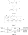
FIG. 5 and FIG. 6 are each a schematic diagram of an oil pump of a hydraulic system according to another embodiment of the present disclosure; -
FIG. 7 is a schematic diagram of a cooling branch of a hydraulic system according to still another embodiment of the present disclosure; -
FIG. 8 is a schematic diagram of constituent modules of a vehicle according to an embodiment of the present disclosure; -
FIG. 9 is a schematic diagram of a method for controlling a hydraulic system according to an embodiment of the present disclosure; and -
FIG. 10 is a schematic diagram of a vehicle according to an embodiment of the present disclosure. - Embodiments of the present disclosure will be described in detail below with reference to the accompanying drawings in which the same or like reference characters refer to the same or like elements or elements having the same or like functions throughout. The embodiments described below with reference to the accompanying drawings are exemplary, and are intended to explain the present disclosure, rather than limiting the present disclosure.
- A
vehicle 1000, a hydraulic system for a powertrain of avehicle 1000, and a method for controlling same according to the embodiments of the present disclosure will be described in detail below with reference to the accompanying drawings. - An embodiment of a first aspect of the present disclosure provides a
hydraulic system 100 for a powertrain of avehicle 1000. Thevehicle 1000 includes one or more of a drive motor, a generator, a clutch, and a transmission system. The hydraulic system includes anoil tank 10, a main cooling oil path m, and a plurality of cooling branches. - As shown in
FIG. 1 , one end of the main cooling oil path m is communicated with the oil tank (10), and afirst oil pump 20 is arranged on the main cooling oil path m. Thefirst oil pump 20 is configured to pump an oil in theoil tank 10 to the cooling branches. The plurality of cooling branches are connected to another end of the main cooling oil path m. An independently controlled control element is arranged on each of the plurality of cooling branches. The control element is configured to control opening and closing of the corresponding cooling branch. The plurality of cooling branches are configured to cool one or more of a drive motor 50a, a clutch 50b, a transmission system 50c, and a generator 50d. - Each of the cooling branches n corresponds to cooling of one power terminal. The power terminal includes but is not limited to the drive motor 50a, the clutch 50b, the transmission system 50c, and the generator 50d.
- Therefore, the cooling branches and the control elements form an integrated cooling valve group structure, and each solenoid valve can independently open or close and adjust the cooling branch, to realize independent flow control, thereby independently adjusting and controlling the cooling flow for each power terminal.
- In some embodiments, the cooling branches at least include a first cooling branch n1, a second cooling branch n2, a third cooling branch n3, and a fourth cooling branch n4. The first cooling branch n1 is configured to cool the drive motor 50a. The second cooling branch n2 is configured to cool the generator 50d. The third cooling branch n3 is configured to cool the clutch 50b. The fourth cooling branch n4 is configured to cool the transmission system 50c. Accordingly, the control elements on the cooling branches are respectively a
first control element 40a, asecond control element 40b, athird control element 40c, and afourth control element 40d. - Therefore, there is a form of energy consumption or multiple energy sources participating in driving at the same time in the operation of a hybrid vehicle. For example, the hybrid vehicle is in an electric vehicle mode (where the drive motor 50a participates in driving, but an engine and the generator 50d do not operate) or a parallel mode (where the engine and the drive motor 50a participate in driving at the same time). The drive motor 50a, the generator 50d, the clutch 50b, and the transmission system 50c are respectively cooled by the first cooling branch n1, the second cooling branch n2, the third cooling branch n3, and the fourth cooling branch n4. A cooler 30 is arranged on the main cooling oil path m to cool the oil in the main cooling oil path m and the cooling branches. This not only can realize the cooling of each power terminal, but also provides a cooling effect.
- The control elements are proportional adjustment solenoid valves, and each of the proportional adjustment solenoid valves is configured to receive a signal sent by a vehicle controller and adjust an opening degree of the proportional adjustment solenoid valve according to the signal. Therefore, the proportional adjusting solenoid valves not only can control the opening and closing of the corresponding cooling branches, but also can adjust the flow rate in each cooling branch as required.
- In the embodiment shown in
FIG. 1 and FIG. 2 , thehydraulic system 100 further includes a driving oil path p. The driving oil path p is connected between theoil tank 10 and the clutch 50b. Asecond oil pump 60 and a pressurecontrol solenoid valve 80 are arranged on the driving oil path p. Thesecond oil pump 60 is configured to pump the oil to the driving oil path p. The driving oil path p is configured to supply the oil to the clutch. - In this way, the driving oil path p is connected between the clutch and the
oil tank 10 and outputs pressure to control the closing and opening of the clutch. When pressure of the clutch needs to be increased according to a driving pressure requirement and current pressure of the clutch, the pressurecontrol solenoid valve 80 is communicated with the driving oil path p and the clutch and controls thesecond oil pump 60 to operate. When pressure of the clutch needs to be relieved, the pressurecontrol solenoid valve 80 blocks the communication between the driving oil path p and the clutch, and communicates theoil tank 10 and the clutch. - In addition, the main cooling oil path m may further be connected to a first safety branch. The first safety branch is located between the cooler 30 and the
first oil pump 20. Afirst safety valve 91 is arranged on the cooling branches. Thefirst safety valve 91 is connected to theoil tank 10 to relieve pressure when oil pressures in the main cooling oil path m and the cooling branches exceed a preset pressure. - Similarly, the driving oil path p may further be connected to a second safety branch. The second safety branch is arranged close to the
second oil pump 60. Thesecond safety valve 92 is connected to theoil tank 10 to relieve pressure when an oil pressure in the driving oil path p exceeds a preset pressure. - In some embodiments, as shown in
FIG. 1 to FIG. 4 , the hydraulic system further includes twopump motors 93, one of thepump motors 93 is in transmission connection with thefirst oil pump 20 and theother pump motor 93 is in transmission connection with thesecond oil pump 60. Thefirst oil pump 20 and thesecond oil pump 60 are respectively controlled by the twopump motors 93, so that the oil pressures in the driving oil path p and the main cooling oil path m can be precisely controlled respectively. - In some other embodiments, as shown in
FIG. 6 , the hydraulic system further includes onepump motor 93, one end of thepump motor 93 is connected to thefirst oil pump 20, and another end of thepump motor 93 is connected to thesecond oil pump 60; - Alternatively, as shown in
FIG. 5 . the hydraulic system further includes onepump motor 93, one end of thepump motor 93 is sequentially in serial transmission connection with thefirst oil pump 20 and thesecond oil pump 60. Thefirst oil pump 20 and thesecond oil pump 60 are simultaneously controlled by the onepump motor 93, thereby simplifying the structure of thehydraulic system 100 and reducing the costs of thehydraulic system 100. - As shown in
FIG. 3 , thehydraulic system 100 further includes a replenishing oil path, the replenishing oil path is connected between the driving oil path p and the main cooling oil path m, and when the replenishing oil path is switched to communicate with the main cooling oil path, the oil in the driving oil path p flows unidirectionally to the main cooling oil path m. - Therefore, when the pressure
control solenoid valve 80 is opened, the oil in theoil tank 10 may be pumped out by thesecond oil pump 60 through the driving oil path p and supplied to the clutch, the replenishing oil path is disconnected, and the driving oil path p and thesecond oil pump 60 are not used to replenish oil to the main cooling oil path m. When the flow in the cooling oil path is insufficient, the cooling oil path needs to be replenished with oil through the driving oil path, and the pressurecontrol solenoid valve 80 is closed. In this case, the replenishing oil path is switched to communicate the driving oil path p with the main cooling oil path m under the action of pressure, and the oil in theoil tank 10 enters the replenishing oil path through the driving oil path p and thesecond oil pump 60, to provide an oil replenishing function for the cooling branches. - In the embodiment shown in
FIG. 4 , the replenishing oil path includes a main replenishing oil path q1 and a regulating oil path q2. Apressure slide valve 71 and a one-way valve 72 are arranged on the main replenishing oil path q1. An inlet of thepressure slide valve 71 is connected to the driving oil path p. An outlet of thepressure slide valve 71 is connected to the main cooling oil path m through the one-way valve 72. Thepressure slide valve 71 is opened when a pressure in the driving oil path p is greater than an opening threshold of thepressure slide valve 71. One end of the regulating oil path q2 is connected to thepressure slide valve 71, another end of the regulating oil path q2 is connected to the driving oil path p. A pressure solenoid valve 73 is further arranged on the regulating oil path q2. The pressure solenoid valve 73 is configured to adjust the opening threshold of thepressure slide valve 71. - In this way, the connection to or disconnection from the replenishing oil path may be realized by controlling the pressure in the driving oil path p. When the pressure in the driving oil path p is within a threshold range, the pressure solenoid valve 73 is controlled to be opened, to switch the regulating oil path q2 to communicate with a
throttle hole 731 of thepressure slide valve 71. The pressure solenoid valve 73 can control the flow rate and the pressure of thethrottle hole 731, to control thepressure slide valve 71 to enter an open state or a closed state, thereby realizing connection and disconnection of the main replenishing oil path q1. Therefore, the use of the electrically controlled pressure solenoid valve 73, thesecond oil pump 60, and thepressure slide valve 71 can realize connection and disconnection of the replenishing oil path, and achieve sensitive response. - In the embodiment shown in
FIG. 7 , the cooling branch further includes a plurality of sub-branches, and asub-branch solenoid valve 40e or asub-branch throttle valve 40f is arranged on each of the sub-branches. Therefore, the plurality of sub-branches can also cool different power terminals. - As shown in
FIG. 8 andFIG. 10 , avehicle 1000 according to an embodiment of a second aspect of the present disclosure includes thehydraulic system 100 of the above embodiments, acontroller 200, apower distribution module 300, apressure calculation module 400, a terminalflow calculation module 500, and a flow coordination module. - The
controller 200 is configured to receive traveling demand information and road condition information. For example, in a conventional driving mode, accelerator pedal information and road slope information are obtained. In an assisted driving mode, driver demand information and road condition prediction information are obtained. In an autonomous driving mode, acceleration requirement information is obtained. - The
power distribution module 300 is configured to calculate rotational speed information and torque information required by each power terminal of the powertrain according to the traveling demand information and the road condition information. The power terminal includes one or more of a drive motor, a generator, a clutch, and a transmission system. - The
pressure calculation module 400 is configured to calculate a driving pressure requirement according to the rotational speed information and the torque information from thepower distribution module 300. Based on power transmission paths of thepower distribution module 300, thepressure calculation module 400 calculates pressure requirements for switching between different power transmission paths, for example, a clutch engagement pressure requirement for switching from an engine serial mode to an engine-driven vehicle mode. - The terminal
flow calculation module 500 is configured to calculate a cooling flow requirement of each power terminal according to the rotational speed information and the torque information from thepower distribution module 300 and oil temperature information of the main cooling oil path. - The
hydraulic coordination module 600 is configured to calculate a rotational speed of the first oil pump, a rotational speed of the second oil pump, the opening degree of the control element, and an opening degree of the pressure control solenoid valve according to the driving pressure requirement and the cooling flow requirement of each power terminal. In other words, rotational speed information of the first oil pump and opening degree information of the pressure control solenoid valve and the control elements are calculated according to the pressure requirement from thepressure calculation module 400 and a summarized flow requirement from the terminalflow calculation module 500. Rotational speed information of the second oil pump is calculated according to the summarized flow requirement of the terminalflow calculation module 500. According to the cooling flow requirement of each power terminal, flow information of the corresponding control element (which may be a solenoid valve) is calculated. Therefore, the terminal flow calculation part calculates, according to performance of each component at different temperatures, a cooling flow requirement corresponding to optimal efficiency of the component. - As shown in
FIG. 9 , an embodiment of a third aspect of the present disclosure provides a method for controlling ahydraulic system 100 for a powertrain of a vehicle, including the following steps. - S1: A power requirement of the powertrain is calculated according to driver demand information and predicted road condition information, and rotational speed information and torque information required by each power terminal of the powertrain are calculated.
- S2: A flow requirement of each power terminal is calculated according to the rotational speed information and the torque information. A pressure requirement of the
hydraulic system 100 is calculated according to a required pressure and the flow requirement of each power terminal. - S3: Rotational speeds of the oil pumps and a pressure and flow control signal required by each solenoid valve are calculated according to the pressure requirement and the flow requirement of each power terminal.
- In this way, a cooling requirement of each component and a total cooling flow requirement are calculated according to a status of the vehicle, and oil pump signals are output, so that the system flow supply can be adjusted as required, thereby reducing the flow loss. By controlling the cooling flow to enable each power terminal to operate in an efficient temperature range, the cooling flow for each power terminal can be distributed as required, thereby improving the system efficiency.
- Refer to Table 1 below for pressures of the
hydraulic system 100 in different modes and the cooling flow for each power terminal.Table 1 Vehicle mode Pressure Cooling flow Drive motor Generator Clutch Transmission system EV / q 1 / q 3 q 4 Parallel connection P1 q 1' q 2' q 3' q 4' Serial connection P2 q 1" q 2" q 3" q 4" - Therefore, in the electric vehicle mode, there is no need to supply oil to the generator 50d; in the parallel mode, the
second oil pump 60 supplies oil to the driving oil path p and thefirst oil pump 20 supplies coolant to the cooling branch; In the serial mode, thesecond oil pump 60 replenishes oil to the main cooling oil path m through the replenishing oil path. - Moreover, the terms "first" and "second" are used herein for purposes of description, and are not intended to indicate or imply relative importance or implicitly point out the number of the indicated technical feature. Therefore, the features defined by "first" and "second" may explicitly or implicitly include one or more features. In the description of the present disclosure, "multiple" and "a plurality of" mean two or more, unless otherwise particularly defined.
- In the description of the specification, the description with reference to the terms "an embodiment", "some embodiments", "example", "specific example", or "some example" and so on means that specific features, structures, materials or characteristics described in connection with the embodiment or example are embraced in at least one embodiment or example of the present disclosure. In the specification, the illustrative expression of the above terms is not necessarily referring to the same embodiment or example. Moreover, the described specific features, structures, materials or characteristics may be combined in any suitable manners in one or more embodiments. In addition, where there are no contradictions, the various embodiments or examples described in this specification and features of various embodiments or examples can be combined by those skilled in the art.
- Although the embodiments of the present disclosure have been illustrated and described above, it is to be understood that the above embodiments are exemplary and not to be construed as limiting the present disclosure, and that changes, modifications, substitutions and alterations can be made by those skilled in the art without departing from the scope of the present disclosure.
Claims (10)
- A hydraulic system for a powertrain of a vehicle, wherein the powertrain comprises one or more of a drive motor, a generator, a clutch, and a transmission system, the hydraulic system comprising:an oil tank;a main cooling oil path, one end of the main cooling oil path being communicated with the oil tank, and a first oil pump and a cooler being arranged on the main cooling oil path; anda plurality of cooling branches, the plurality of cooling branches being connected to another end of the main cooling oil path, the first oil pump being configured to pump an oil in the oil tank to the cooling branches, a control element being arranged on each of the cooling branches, the control element being configured to control opening and closing of the corresponding cooling branch, and the plurality of cooling branches being configured to cool one or more of the drive motor, the generator, the clutch, and the transmission system.
- The hydraulic system for a powertrain of a vehicle according to claim 1, wherein the cooling branches at least comprise a first cooling branch, a second cooling branch, a third cooling branch, and a fourth cooling branch, the first cooling branch is configured to cool the drive motor, the second cooling branch is configured to cool the generator, the third cooling branch is configured to cool the clutch, and the fourth cooling branch is configured to cool the transmission system.
- The hydraulic system for a powertrain of a vehicle according to any one of claims 1 to 2, wherein the control elements are proportional adjustment solenoid valves, and each of the proportional adjustment solenoid valves is configured to receive a signal sent by a vehicle controller and adjust an opening degree of the proportional adjustment solenoid valve according to the signal.
- The hydraulic system for a powertrain of a vehicle according to any one of claims 1 to 3, further comprising a driving oil path, the driving oil path is connected between the oil tank and the clutch, a second oil pump and a pressure control solenoid valve are arranged on the driving oil path, the second oil pump is configured to pump the oil to the driving oil path, and the driving oil path is configured to control engagement and disengagement of the clutch.
- The hydraulic system for a powertrain of a vehicle according to any one of claims 1 to 4, further comprising two pump motors, one of the pump motors being in transmission connection with the first oil pump and the other pump motor being in transmission connection with the second oil pump; orfurther comprising one pump motor, one end of the pump motor being connected to the first oil pump, and another end of the pump motor being connected to the second oil pump; orfurther comprising one pump motor, one end of the pump motor being sequentially in serial transmission connection with the first oil pump and the second oil pump.
- The hydraulic system for a powertrain of a vehicle according to claim 4, further comprising a replenishing oil path, the replenishing oil path being connected between the driving oil path and the main cooling oil path, and wherein when the replenishing oil path is switched to communicate with the main cooling oil path, the oil in the driving oil path flows unidirectionally to the main cooling oil path.
- The hydraulic system for a powertrain of a vehicle according to claim 6, wherein the replenishing oil path comprises:a main replenishing oil path, a pressure slide valve and a one-way valve are arranged on the main replenishing oil path, an inlet of the pressure slide valve is connected to the driving oil path, an outlet of the pressure slide valve is connected to the main cooling oil path through the one-way valve, and the pressure slide valve is opened when a pressure in the driving oil path is greater than an opening threshold of the pressure slide valve; anda regulating oil path, one end of the regulating oil path is connected to the pressure slide valve, another end of the regulating oil path is connected to the driving oil path, a pressure solenoid valve is further arranged on the regulating oil path, the pressure solenoid valve is configured to adjust the opening threshold of the pressure slide valve.
- The hydraulic system for a powertrain of a vehicle according to any one of claims 1-3, wherein the cooling branch further comprises a plurality of sub-branches, and a sub-branch solenoid valve or a sub-branch throttle valve is arranged on each of the sub-branches.
- A vehicle, comprising:a hydraulic system according to any one of claims 4-8;a controller, configured to receive traveling demand information and road condition information;a power distribution module, configured to calculate rotational speed information and torque information required by each power terminal of the powertrain according to the traveling demand information and the road condition information, wherein the power terminal comprises one or more of a drive motor, a generator, a clutch, and a transmission system;a pressure calculation module, configured to calculate a driving pressure requirement according to the rotational speed information and the torque information from the power distribution module;a terminal flow calculation module, configured to calculate a cooling flow requirement of each power terminal according to the rotational speed information and the torque information from the power distribution module and oil temperature information of the main cooling oil path; anda hydraulic coordination module, configured to calculate a rotational speed of the first oil pump, a rotational speed of the second oil pump, the opening degree of the control element, and an opening degree of the pressure control solenoid valve according to the driving pressure requirement and the cooling flow requirement of each power terminal.
- A method for controlling a hydraulic system for a powertrain of a vehicle according to any one of claims 4-8, comprising:calculating rotational speed information and torque information required by each power terminal of the powertrain according to the traveling demand information and the road condition information, wherein the power terminal comprises one or more of a drive motor, a generator, a clutch, and a transmission system;calculating a driving pressure requirement and a cooling flow requirement of each power terminal according to the rotational speed information and the torque information required by each power terminal; andcalculating a rotational speed of the first oil pump, a rotational speed of the second oil pump, a flow rate in the cooling branch, and an opening degree of the pressure control solenoid valve according to the driving pressure requirement and the cooling flow requirement of each power terminal.
Applications Claiming Priority (2)
| Application Number | Priority Date | Filing Date | Title |
|---|---|---|---|
| CN202110406463.8A CN115217807A (en) | 2021-04-15 | 2021-04-15 | Vehicle, hydraulic system for a drive train of a vehicle and method for controlling the same |
| PCT/CN2022/085872 WO2022218230A1 (en) | 2021-04-15 | 2022-04-08 | Vehicle, hydraulic system for powertrain of vehicle, and control method therefor |
Publications (1)
| Publication Number | Publication Date |
|---|---|
| EP4299920A1 true EP4299920A1 (en) | 2024-01-03 |
Family
ID=83605320
Family Applications (1)
| Application Number | Title | Priority Date | Filing Date |
|---|---|---|---|
| EP22787456.7A Pending EP4299920A1 (en) | 2021-04-15 | 2022-04-08 | Vehicle, hydraulic system for powertrain of vehicle, and control method therefor |
Country Status (7)
| Country | Link |
|---|---|
| US (1) | US20240010066A1 (en) |
| EP (1) | EP4299920A1 (en) |
| JP (1) | JP2024515500A (en) |
| CN (1) | CN115217807A (en) |
| AU (1) | AU2022259240A1 (en) |
| BR (1) | BR112023021298A2 (en) |
| WO (1) | WO2022218230A1 (en) |
Family Cites Families (6)
| Publication number | Priority date | Publication date | Assignee | Title |
|---|---|---|---|---|
| JP3758631B2 (en) * | 2002-10-15 | 2006-03-22 | 三菱ふそうトラック・バス株式会社 | Motor cooling structure for hybrid electric vehicle |
| DE102011118574A1 (en) * | 2011-11-09 | 2013-05-16 | Getrag Getriebe- Und Zahnradfabrik Hermann Hagenmeyer Gmbh & Cie Kg | Powertrain cooling arrangement and method of operating the same |
| DE102012010322A1 (en) * | 2012-05-21 | 2013-11-21 | Getrag Getriebe- Und Zahnradfabrik Hermann Hagenmeyer Gmbh & Cie Kg | Cooling arrangement and cooling method for automotive powertrain |
| CN110219971B (en) * | 2019-05-14 | 2021-10-12 | 中国第一汽车股份有限公司 | Electric hydraulic cooling and lubricating system of automatic transmission and control system thereof |
| CN211649006U (en) * | 2019-09-06 | 2020-10-09 | 深圳臻宇新能源动力科技有限公司 | Automatic transmission cooling and lubricating system and vehicle with same |
| CN112112956A (en) * | 2020-09-07 | 2020-12-22 | 吉泰车辆技术(苏州)有限公司 | Hydraulic control system of gearbox |
-
2021
- 2021-04-15 CN CN202110406463.8A patent/CN115217807A/en active Pending
-
2022
- 2022-04-08 AU AU2022259240A patent/AU2022259240A1/en active Pending
- 2022-04-08 BR BR112023021298A patent/BR112023021298A2/en unknown
- 2022-04-08 WO PCT/CN2022/085872 patent/WO2022218230A1/en active Application Filing
- 2022-04-08 JP JP2023560374A patent/JP2024515500A/en active Pending
- 2022-04-08 EP EP22787456.7A patent/EP4299920A1/en active Pending
-
2023
- 2023-09-25 US US18/372,249 patent/US20240010066A1/en active Pending
Also Published As
| Publication number | Publication date |
|---|---|
| JP2024515500A (en) | 2024-04-10 |
| WO2022218230A1 (en) | 2022-10-20 |
| AU2022259240A1 (en) | 2023-10-19 |
| CN115217807A (en) | 2022-10-21 |
| US20240010066A1 (en) | 2024-01-11 |
| BR112023021298A2 (en) | 2023-12-19 |
Similar Documents
| Publication | Publication Date | Title |
|---|---|---|
| CN109282028B (en) | Hydraulic control system of hybrid power vehicle and control method thereof | |
| CN106593978B (en) | Hybrid vehicle and its cooling hydraulic system of motor | |
| US7517296B2 (en) | Variable motor/generator cooling control system for electrically variable hybrid vehicular transmissions | |
| CN209212951U (en) | Hybrid vehicle hydraulic control system | |
| CN213088564U (en) | Hydraulic system of hybrid transmission | |
| CN109826948B (en) | Hydraulic control system | |
| CN219509915U (en) | Hydraulic system and vehicle control system | |
| WO2021244479A1 (en) | Vehicle hydraulic control system and method | |
| CN110469663A (en) | A kind of transmission hydraulic control system and vehicle | |
| KR20160147928A (en) | Hydraulic system of a transmission with a plurality of pressure regulating valves | |
| JP2000205301A (en) | Oil feeder | |
| CN216643067U (en) | Hydraulic control device for wet-type double-clutch hybrid variable speed system | |
| CN213472767U (en) | Power assembly and vehicle | |
| EP4299920A1 (en) | Vehicle, hydraulic system for powertrain of vehicle, and control method therefor | |
| CN213920655U (en) | Hybrid vehicle and hydraulic system, gearbox and power system thereof | |
| CN213017371U (en) | Double-pump coupling hydraulic control system of automobile gearbox | |
| CN218440578U (en) | Automatic gearbox hydraulic control system and vehicle | |
| CN216478189U (en) | Hydraulic system and vehicle | |
| CN213472766U (en) | Power assembly and vehicle | |
| CN115450967A (en) | Hydraulic system for hybrid transmission and automobile | |
| CN113883264A (en) | Hydraulic system of hybrid power vehicle | |
| CN109027216B (en) | Hydraulic system suitable for new energy automobile automatic gearbox | |
| KR20220120744A (en) | Hybrid powertrain cooling system of vehicle | |
| US10316962B2 (en) | Vehicle transmission with accumulator | |
| CN110529584A (en) | Power system cooling device |
Legal Events
| Date | Code | Title | Description |
|---|---|---|---|
| STAA | Information on the status of an ep patent application or granted ep patent |
Free format text: STATUS: THE INTERNATIONAL PUBLICATION HAS BEEN MADE |
|
| PUAI | Public reference made under article 153(3) epc to a published international application that has entered the european phase |
Free format text: ORIGINAL CODE: 0009012 |
|
| STAA | Information on the status of an ep patent application or granted ep patent |
Free format text: STATUS: REQUEST FOR EXAMINATION WAS MADE |
|
| 17P | Request for examination filed |
Effective date: 20230927 |
|
| AK | Designated contracting states |
Kind code of ref document: A1 Designated state(s): AL AT BE BG CH CY CZ DE DK EE ES FI FR GB GR HR HU IE IS IT LI LT LU LV MC MK MT NL NO PL PT RO RS SE SI SK SM TR |