EP4299480A1 - Low maintenance bucket elevator for moving heavy and/or abrasive material, as well as line for moving heavy and/or abrasive material and method of use of the bucket elevator - Google Patents
Low maintenance bucket elevator for moving heavy and/or abrasive material, as well as line for moving heavy and/or abrasive material and method of use of the bucket elevator Download PDFInfo
- Publication number
- EP4299480A1 EP4299480A1 EP23181894.9A EP23181894A EP4299480A1 EP 4299480 A1 EP4299480 A1 EP 4299480A1 EP 23181894 A EP23181894 A EP 23181894A EP 4299480 A1 EP4299480 A1 EP 4299480A1
- Authority
- EP
- European Patent Office
- Prior art keywords
- unloading
- buckets
- abrasive material
- heavy
- bucket elevator
- Prior art date
- Legal status (The legal status is an assumption and is not a legal conclusion. Google has not performed a legal analysis and makes no representation as to the accuracy of the status listed.)
- Granted
Links
Images




Classifications
-
- B—PERFORMING OPERATIONS; TRANSPORTING
- B65—CONVEYING; PACKING; STORING; HANDLING THIN OR FILAMENTARY MATERIAL
- B65G—TRANSPORT OR STORAGE DEVICES, e.g. CONVEYORS FOR LOADING OR TIPPING, SHOP CONVEYOR SYSTEMS OR PNEUMATIC TUBE CONVEYORS
- B65G17/00—Conveyors having an endless traction element, e.g. a chain, transmitting movement to a continuous or substantially-continuous load-carrying surface or to a series of individual load-carriers; Endless-chain conveyors in which the chains form the load-carrying surface
- B65G17/16—Conveyors having an endless traction element, e.g. a chain, transmitting movement to a continuous or substantially-continuous load-carrying surface or to a series of individual load-carriers; Endless-chain conveyors in which the chains form the load-carrying surface comprising individual load-carriers which are pivotally mounted, e.g. for free-swinging movement
-
- B—PERFORMING OPERATIONS; TRANSPORTING
- B65—CONVEYING; PACKING; STORING; HANDLING THIN OR FILAMENTARY MATERIAL
- B65G—TRANSPORT OR STORAGE DEVICES, e.g. CONVEYORS FOR LOADING OR TIPPING, SHOP CONVEYOR SYSTEMS OR PNEUMATIC TUBE CONVEYORS
- B65G17/00—Conveyors having an endless traction element, e.g. a chain, transmitting movement to a continuous or substantially-continuous load-carrying surface or to a series of individual load-carriers; Endless-chain conveyors in which the chains form the load-carrying surface
- B65G17/30—Details; Auxiliary devices
- B65G17/32—Individual load-carriers
- B65G17/36—Individual load-carriers having concave surfaces, e.g. buckets
-
- B—PERFORMING OPERATIONS; TRANSPORTING
- B65—CONVEYING; PACKING; STORING; HANDLING THIN OR FILAMENTARY MATERIAL
- B65G—TRANSPORT OR STORAGE DEVICES, e.g. CONVEYORS FOR LOADING OR TIPPING, SHOP CONVEYOR SYSTEMS OR PNEUMATIC TUBE CONVEYORS
- B65G17/00—Conveyors having an endless traction element, e.g. a chain, transmitting movement to a continuous or substantially-continuous load-carrying surface or to a series of individual load-carriers; Endless-chain conveyors in which the chains form the load-carrying surface
- B65G17/30—Details; Auxiliary devices
- B65G17/48—Controlling attitudes of load-carriers during movement
-
- B—PERFORMING OPERATIONS; TRANSPORTING
- B65—CONVEYING; PACKING; STORING; HANDLING THIN OR FILAMENTARY MATERIAL
- B65G—TRANSPORT OR STORAGE DEVICES, e.g. CONVEYORS FOR LOADING OR TIPPING, SHOP CONVEYOR SYSTEMS OR PNEUMATIC TUBE CONVEYORS
- B65G47/00—Article or material-handling devices associated with conveyors; Methods employing such devices
- B65G47/34—Devices for discharging articles or materials from conveyor
- B65G47/38—Devices for discharging articles or materials from conveyor by dumping, tripping, or releasing load carriers
- B65G47/40—Devices for discharging articles or materials from conveyor by dumping, tripping, or releasing load carriers by tilting conveyor buckets
-
- B—PERFORMING OPERATIONS; TRANSPORTING
- B65—CONVEYING; PACKING; STORING; HANDLING THIN OR FILAMENTARY MATERIAL
- B65G—TRANSPORT OR STORAGE DEVICES, e.g. CONVEYORS FOR LOADING OR TIPPING, SHOP CONVEYOR SYSTEMS OR PNEUMATIC TUBE CONVEYORS
- B65G2201/00—Indexing codes relating to handling devices, e.g. conveyors, characterised by the type of product or load being conveyed or handled
- B65G2201/04—Bulk
- B65G2201/045—Sand, soil and mineral ore
Definitions
- the present invention is generally relates to the technical field of moving heavy and/or abrasive materials, such as for example marble, quartz or the like, and in particular it relates to a low maintenance bucket elevator for moving heavy and/or abrasive materials, a line for moving heavy and/or abrasive material and a method of use of the bucket elevator.
- abrasive material and derivatives is used to indicate all natural or artificial materials, such as for example quartz, silica, salts and the like which, being of the removal action type, can lead to wear phenomena on metals, especially steel and the like.
- conveyor belts In order to enable the conveyed heavy and/or abrasive material to reach the raised unloading station, conveyor belts require paths with low slope and with particular trajectories, for example zig-zag-like.
- the conveyor belts are therefore particularly cumbersome, not versatile in terms of configurations and therefore poorly efficient.
- conveyor belts require highly frequent maintenance, given that the abrasive material tends to rapidly damage the moving components thereof, in particular the support belt.
- An object of the present invention is to at least partially overcome the drawbacks observed above, by providing a bucket elevator for moving heavy and/or abrasive materials that is particularly efficient and reliable.
- a further object of the invention is to provide a bucket elevator for moving heavy and/or abrasive materials that is particularly compact and versatile.
- a further object of the invention is to provide a low maintenance bucket elevator for moving heavy and/or abrasive materials.
- a further object of the invention is to provide a bucket elevator for moving heavy and/or abrasive materials that is particularly cost-effective.
- a further object of the invention is to provide a line for moving heavy and/or abrasive material that is particularly versatile.
- a further object of the invention is to provide a method of use of a bucket elevator for moving heavy and/or abrasive material that is particularly reliable and easy to implement.
- a low maintenance bucket elevator 1 for moving heavy and/or abrasive materials.
- the heavy and/or abrasive material to be moved may for example be marble, quartz, silica or the like.
- the bucket elevator 1 in question may also be used for moving light materials, for example light food products such as pasta, seeds, legumes, dry fruits or the like, and possibly even abrasive, such as for example light food products characterised by a high percentage of salt, in particular fine salt, such as for example potato chips covered with salt and the like, without departing from the scope of protection of the attached claims.
- the bucket elevator 1 may be suitably sized and configured to move the heavy and/or abrasive material from a first lower height to a second higher height following a determined path.
- the bucket elevator 1 may comprise a plurality of buckets 4 , which may be designed to convey the heavy and/or abrasive material to be moved.
- each bucket 4 may extend along a longitudinal axis T and it may define a prism structure 40 .
- the latter may also include a bottom wall 45 and four side walls 43 , 43' , 44 , 44', defining - as a whole - a compartment 47 accessible by an opening 48 as shown in FIG. 2 .
- the walls 43 , 43' may be mutually faced and lie on incident planes with respect to the longitudinal axis T along which the walls 43 , 43' extend, while the walls 44 , 44' may also be mutually faced and lie on incident planes with respect to a transversal axis U, the latter substantially perpendicular with respect to the axis T.
- the compartment 47 may therefore be designed to house the material to be moved.
- the use of a plurality of buckets 4 may allow to minimise the relative movement of the heavy and/or abrasive material and - as a result - maintain both the composition and microgranularity thereof, given that the containment in the compartment 47 limits the possible jerky and/or translatory movement thereof.
- the buckets 4 may be suitably sized to contain a determined amount of material, for example at least 40 kg, preferably 40 - 50 kg.
- the walls 43 , 43' , 44 , 44' and 45 may define a containment volume of at least 16 dm 3 , preferably 16 - 20 dm 3 .
- this will therefore also allow to change the capacity of the bucket elevator 1 in question, depending on the type of material conveyed and the type of path to be travelled through.
- the bucket elevator 1 may comprise a loading area 2 at the lower height where the buckets 4 may be loaded with the material to be moved.
- the bucket elevator 1 may also comprise a plurality of areas 2 for loading the buckets 4 with the material to be moved without departing from the scope of protection of the attached claims.
- the buckets 4 may be loaded using a vibrating screening machine or the like and/or conveyor belts, arranged at the loading area 2 and suitably configured to unload the precise amount of material in each bucket 4 so as to have a homogeneous and constant distribution of the product on the buckets.
- the bucket elevator 1 may comprise an unloading area 3 at the higher height, for unloading the material moved by the buckets 4 .
- the unloading areas 3 may therefore actually be arranged at the points where one desires to unload the moved material.
- the buckets 4 may further unload the material within one or more hoppers: the latter may therefore be suitably sized and arranged at each unloading area 3 to allow to collect the material therein.
- the bucket elevator 1 may comprise suitable movement means 5 which may therefore be operatively connected with the buckets 4 to allow the movement thereof between the loading area 2 and the unloading areas 3 .
- the buckets 4 may be moved from the loading area 2 to the unloading areas 3 following a predetermined path to allow the unloading of the moved material.
- the emptied buckets 4 may therefore be moved from the unloading areas 3 to the loading area 2 following a complementary path so as to be filled with the material to be moved once again.
- the bucket elevator 1 may further comprise a support structure 7 which may be self-supporting and preferably made of metal material, adapted to confer structural unity to the bucket elevator 1.
- the support structure 7 may also allow to increase the safety and protection level of possible operators in the working area of the bucket elevator 1 .
- the bucket elevator 1 may also further comprise an outer support structure suitably sized to confer further structural stability to the bucket elevator 1 and therefore ensure greater safety, further minimising any vibrations both due to the size of the bucket elevator 1 and the high loads moved by the same.
- the bucket elevator 1 may define a portion 11 for advancing the buckets 4 along an axis X' and a portion 12 for advancing along an axis X".
- the advancement portion 11 may be at the loading area 2
- the advancement portion 12 may be at the unloading area 3 .
- the unloading areas 3 may be consecutive and arranged at pre-established distances along the axis X' of the advancement portion 12 .
- the bucket elevator 1 may also comprise a portion 13 for advancing along an axis Z, the latter interposed between the advancement portion 11 and the advancement portion 12 , as shown in FIGS. 4 , 5A and 5B .
- the portion 11 may extend for 10 - 12 m
- the portion 12 may extend for 25 - 30 m
- the portion 13 may extend for 10 - 12 m.
- the advancement portion 11 and advancement portion 12 may therefore be mutually spaced apart.
- the axes X' and X" respectively of the advancement portion 11 and of the advancement portion 12 may be substantially parallel.
- the axis Z may be perpendicular to the axes X' and X" respectively of the advancement portion 11 and of the advancement portion 12.
- advancement portion 13 may extend vertically with respect to the advancement portion 11 and the advancement portion 12 , which may instead extend horizontally.
- the axis Z may also not be perpendicular to the axes X' and X", that is the third advancement portion 13 may extend obliquely with respect to the first advancement portion 11 and to the second advancement portion 12 , which may however remain substantially parallel to one with respect to the other, without departing from the scope of protection of the attached claims.
- the axes X' and X" may have the same direction, where the direction is defined by the advancement direction of the buckets 4 .
- the bucket elevator 1 may have a so-called Z-shaped configuration and shown in FIG. 5A .
- the axes X' and X" may have substantially opposite direction, where the direction is defined by the advancement direction of the buckets 4 .
- the bucket elevator 1 may have a so-called C-shaped configuration and shown in FIG. 5B .
- the C-shaped configuration may be used should there arise the need to contain the overall dimensions of the bucket elevator 1 .
- the movement means 5 may comprise a pair of chains 50 which are closed and movable along the advancement portions 11 , 12 and 13 .
- the chains 50 may remain mutually facing each other and spaced apart with respect to the axes X' , X" and Z along the respective advancement portions 11, 12 and 13 , as particularly shown in FIG. 4 .
- the use of a pair of chains 50 is particularly advantageous, given that it allows to move considerable loads and further obtain a significant speed for moving the buckets 4 .
- each bucket 4 may be laterally connected to the chains 50 through suitable connection means 9 .
- connection means 9 will not jeopardise the connection means 9 and the buckets 4 may be rotatably coupled to the pair of chains 50 .
- the rotatable coupling between the buckets 4 and the pair of chains 50 may therefore allow the free rotation of the buckets 4 around the rotation axis thereof, which - in this case - coincides with the longitudinal axis T .
- the expression free rotation of the buckets 4 around the rotation axis thereof T is used to indicate that the rotary movement of each bucket 4 around the rotation axis thereof T may be independent, at least in the advancement portion 12 and - as a result - in proximity of the unloading areas 3 , from the translation movement imparted by the movement means 5 thereon.
- each bucket 4 will be substantially perpendicular to the axis X" of the advancement portion 12 .
- each bucket may freely rotate around rotation axis T thereof even at the advancement portion 11 and/or at the advancement portion 12 , without departing from the scope of protection of the attached claims.
- each bucket 4 may further be by an angle ⁇ measuring 100° -150°, preferably 130° - 140° with respect to the plane defined by the advancement portion 12 .
- Each pinion 51 may therefore be peripherally coupled with the respective chain 50 to allow the movement thereof and therefore also the buckets 4 .
- the bucket elevator 1 may further comprise suitable unloading means 6 adapted to allow the unloading of the buckets 4 at the unloading areas 3 .
- the unloading means 6 may therefore be arranged at each unloading area 3 .
- the aforementioned unloading means 6 may therefore act on the buckets 4 to allow the rotation thereof around the respective rotation axis T and the ensuing unloading of the material at the one or more unloading areas 3 , as will be clearer in the description hereinafter.
- the bucket elevator 1 may also comprise suitable control means 8 , which may act on the unloading means 6 and be suitably configured to allow the selective unloading of the buckets 4 at the one or more unloading areas 3 .
- the expression selective unloading of the buckets 4 is used to indicate that the material moved by the bucket 4 may therefore be unloaded by way of response to a command imparted by the control means 8 and therefore only in the unloading areas 3 which were selected by the latter.
- control means 8 may select one or more unloading areas 3 and therefore act on the respective unloading means 6 for unloading the buckets 4 in the selected unloading areas 3 .
- the unloading means 6 selected by the control means 8 may act on the buckets 4 at the unloading areas 3 of interest therefore so as to allow the unloading thereof.
- control means 8 may further be configured to control the advancement of the movement means 5 .
- the unloading means 6 may comprise one or more abutment elements 61 and one or more counteracting elements 62 , which may be suitably shaped and mutually interact to allow the rotation of the buckets 4 around the rotation axis thereof T at the one or more selected unloading areas 3.
- the support structure 7 may comprise one or more counteracting elements 62
- the buckets 4 may comprise one or more abutment elements 61 .
- the support structure 7 may comprise the one or more abutment elements 61
- the buckets 4 may comprise the one or more counteracting elements 62 , without departing from the scope of protection of the attached claims.
- the unloading means 6 may also comprise pairs of abutment elements 61 and pairs of counteracting elements 62 , mutually spaced apart with respect to the axis X" of the advancement portion 12 , without departing from the scope of protection of the attached claims.
- each bucket 4 may comprise one or more suitably shaped cam elements 61' , which may define the one or more abutment elements 61
- the support structure 7 may comprise one or more pivots 62' , which may define the one or more counteracting elements 62 .
- the pivots 62' may further be movable between a retracted position and an extended position along a direction perpendicular to the axis X" of the advancement portion 12 .
- the cam element 61' of the buckets 4 may actually abut against the pivot 62' arranged at the unloading area 3 of interest.
- the cam element 61' may therefore rotate around the axis T of the bucket 4 switching from an initial inoperative position to a maximum rotation position.
- cam element 61' is integrally joined with the respective bucket 4 , even the latter may - as a result - rotate around the rotation axis T .
- the profile of the cam element 61' may be such to allow a maximum rotation of the bucket 4 in an angular range ⁇ between 100° -150°, preferably 130° -140° with respect to the plane defined by the advancement portion 12, an angular range measured between the latter and the edge area of the bucket 4 as particularly shown in FIG. 6 .
- the cam profile 61' may rotate in the opposite direction to return to the initial inoperative position thereof.
- connection means 9 may further include at least one interface element 63 and at least one pair of fixing elements 64' and 64".
- the interface element 63 may be substantially T-shaped.
- the interface element 63 may be coupled to at least one side wall 44 and/or 44' , while the fixing elements 64' and 64" may be obtained on the interface element 63 or they may be coupled with the latter in a longitudinal direction so as to be mutually superimposed.
- the element 64' may be positioned above the element 64" .
- cam 61' may be removably coupled with such elements 64' and 64" .
- the cam 61' may have a portion 610" removably fixed to the element 64" and a portion 610' prismatically coupled to the element 64'.
- the elements 64' and 64" may be substantially cylindrical.
- the element 64' may have a portion 640' with a first diameter coupled with the interface 63 and an opposite portion 640" having a diameter smaller than the first.
- the portion 610' of the cam 61' may include an opening 6100 counter-shaped with respect to the portion 640' , that is it may have a substantially circular or arc-shaped base with a circumference having diameter substantially equal to the diameter of the portion 640' .
- the opening walls 6100 may be in contact with at least one part of the outer surface of the portion 640' .
- the portion 610" may instead be removably fixed to the element 64" in a per se known manner for example using a screw 6400 or the like.
- control means 8 may be suitably configured to selectively act on the pivots 62' and to move them from the retracted position to the extended position to enable the unloading area 3 and vice versa to disable it.
- control means 8 may include one or more solenoid valves or pneumatic valves or any electric actuation device suitably connected with the pivots 62' to move them from the retracted position to the extended position and vice versa.
- control means 8 may also comprise a special control software, which is preprogrammed or which can be set by an operator from an operator's panel.
- control means 8 may therefore allow to select the unloading areas 3 of interest in which the buckets 4 may subsequently unload the moved heavy and/or abrasive material.
- control means 8 may also be suitably configured to select a fixed safety unloading area 3 , so as to ensure - in any case - the unloading of the material from the buckets 4 at the latter.
- the buckets 4 may actually unload the moved material and therefore return - empty - to the loading area 2 so as to be once again loaded with material to be moved.
- each bucket 4 may further comprise a support edge 41 and a connection edge 42, respectively arranged long the edge of the wall 43 and 43' , as shown in FIGS. 1 and 2 .
- the support edge 41 and the connection edge 42 may therefore be faced and mutually spaced apart with respect to the axis T .
- connection edge 42 of a first bucket 4 may be suitably shaped to be mutually superimposed to the support edge 41 of a second consecutive bucket 4 , when both the first bucket 4 cand the second bucket 4 are in the portion 11 or in the portion 12 , to allow the stable connection between the buckets 4 .
- the expression stable connection is used to indicate that the buckets 4 may be constrained to each other and therefore they may move integrally joined in the same movement direction.
- connection edge 42 of a bucket 4 on the support edge 41 of a consecutive bucket 4 may occur when the axes U of the buckets 4 are substantially coincident, or particularly at the loading area 2 and/or at the unloading areas 3, as shown in FIGS. 1 and 4 .
- connection edge 42 may rest against support edge 41 at the portion 11 , in particular at the loading area 2 .
- the support edge 41 may rest against the connection edge 42 at the portion 12 .
- connection edge 42 may rest against the support edge 41 even at the portion 12 and therefore at the unloading area 3 or only at the latter and vice versa, that is the support edge 41 may rest against the connection edge 42 even at the portion 11 or only at the latter without departing from the scope of protection of the attached claims.
- connection edge 42 of a bucket 4 may allow to prevent the abrasion thereof and therefore extend the useful life of the buckets 4 .
- connection edge 42 may further have a suitably shaped profile and, preferably, a sloping profile.
- connection edge 42 of the buckets 4 may therefore define an angle ⁇ between 45° - 70°, preferably between 50° - 65° as particularly shown in FIG. 9D , defined between the connection edge 42 and the wall 43' .
- connection edge 42 may have any suitably shaped profile, provided that it allows the stable connection of the buckets 4 at the one or more loading 2 and unloading 3 areas, without departing from the scope of protection of the attached claims.
- the sloping profile of the connection edge 42 may therefore allow to minimise the deposition and the resulting stagnation of any material thereon, in particular if the heavy and/or abrasive material - both when the buckets 4 are loaded with the material to be moved and possibly when they unload the moved material - respectively at the one or more loading and unloading areas.
- connection edges 42 for example brushes or the like, positioned at the area 2 for loading the buckets 4 .
- the special means for cleaning the connection edges 42 of the buckets 4 may therefore mechanically remove the material therefrom.
- the material removed from a bucket 4 may therefore be collected in a bucket 4 adjacent thereto.
- the support structure 7 of the bucket elevator 1 may be substantially open and comprise a plurality of removable parts, to facilitate the detection of problems and malfunctions of the bucket elevator 1 .
- this solution allows to significantly reduce the time required for routine and extraordinary maintenance of the bucket elevator 1 , with a resulting reduction of machine downtime and increase in the overall efficiency thereof.
- each bucket 4 may then comprise a longitudinal reinforcement bar 46 preferably positioned in proximity of the connection edge 42 and integrally joined with the bucket 4 , as shown in FIG. 2 .
- longitudinal reinforcement bar 46 may also be positioned in another point of the bucket 4 without departing from the scope of protection of the attached claims.
- it may be possibly positioned on the bottom wall 45 , to lower the barycentre of the bucket 4 and confer - as a result - greater stability to the latter during the movement and the loading/unloading.
- each bucket 4 may include one or more reinforcement bars 46 positioned in several points thereof, for example one or more bars 46 positioned in proximity of the connection edge 42 and/or one or more bars 46 positioned on the bottom wall 45 and/or one or more bars 46 positioned in any other point of the bucket 4 .
- the presence of the one or more longitudinal reinforcement bars 46 will allow to increase the torsional strength of the bucket and - as a result - the useful life thereof.
- the one or more longitudinal reinforcement bars 46 may for example be made of steel.
- each bucket 4 may include a reinforcement bar 46 integrally joined with connection edge 42 .
- the reinforcement bar 46 may include a portion 460' integrally joined with the side wall 43' of the bucket 4 and a portion 460" integrally joined with the connection edge 42 .
- the portion 460" and the connection edge 42 may therefore defining a substantially V-shaped configuration which may allow to define the above-mentioned sloping profile of the connection edge 42 to minimise the deposition and stagnation of material thereon.
- connection edge 42 may interact with the support edge 41 and in particular the portion 460" may rest on the latter at the portions 11 and/or 12 mentioned above.
- the portion 460' may contribute to prevent the above-mentioned torsions due to the large dimensions of the bucket 4 as well as the weight of the conveyed material.
- connection edge 42 and the bar 46 may be obtained starting from a single metal lip 4246 whose folding may define the edge 42 , the portions 460' and 460" .
- the grooves 4200 may be welded in a per se known manner, just like the portion 460' to integrally join it to the wall 43' .
- each pinion 51 may further be modular and therefore consist of a defined number of sectors.
- each pinion 51 may be made with three pieces which can be assembled and disassembled with respect to each other.
- the drive shafts may be removable from the support structure 7 due to the presence of a plurality of removable parts, should there be a malfunction or should the latter be damaged.
- sensors such as for example accelerometers, strain gauges, or load cells, for constantly monitoring the moving components and therefore allow a predictive maintenance thereof.
- they may be actually positioned at the support structure 7 and/or at the modular pinions and/or at the movement means 5 , to monitor the mechanical stresses and therefore detect possible malfunctions and/or failures.
- a line L for moving the heavy and/or abrasive material to be moved which may therefore consecutively comprise:
- the conveyor belts NT may extend along an axis Y incident or at most perpendicular to the axis X " of the second portion 12 for advancing the bucket elevator 1 .
- the presence of multiple conveyor belts NT in proximity of the unloading areas 3 of the bucket elevator 1 may therefore allow to separate the heavy and/or abrasive material, which may be stored or subjected to possible subsequent processes.
- anti-contamination elements for identifying contaminants in the moved heavy and/or abrasive material.
- a bucket 4 for a bucket elevator as described above, having the above-mentioned bottom wall 45 , side walls 43 , 43' , 44 , 44' , compartment 47 accessible from an opening 48 , support edge 41 , connection edge 42 and one or more reinforcement bars 46 .
- the latter may include all the characteristics specifically described above.
- the bucket elevator 1 for moving the heavy and/or abrasive material, for example marble, quartz, silica or the like, from a first lower height to a second higher height.
- the heavy and/or abrasive material for example marble, quartz, silica or the like
- the buckets 4 may be filled with the heavy and/or abrasive material to be moved at the loading area 2 .
- the step for loading the buckets 4 may be carried out automatically, using vibrating screening machines or the like, or even manually, through an operator designated to load the buckets 4 with the heavy and/or abrasive material.
- Such selection may therefore be carried out from an operator's panel through a dedicated software.
- control means 8 may act on the unloading means 6 so as to move the pivots 62' arranged at the selected unloading means 3 from the retracted position to the extended position.
- the pivots 62' in extended position may therefore cooperate with the cam profiles 61' of the buckets 4 to allow the latter to unload the heavy and/or abrasive material at the selected unloading areas 3 .
- the buckets 4 filled with the heavy and/or abrasive material may therefore be moved using means 5 for moving from the loading area 2 - arranged at the lower height - until the one or more selected unloading areas 3 arranged at the higher height.
- the buckets 4 may therefore selectively unload the heavy and/or abrasive material in the one or more selected unloading areas 3 .
- Such method of use may further be implemented to be carried out iteratively.
- the method of use thus described has the particular advantage of being easy to implement and particularly reliable, thanks to the use of a dedicated software.
- Such bucket elevator 1 is also particularly efficient from an energy point of view, given that it allows to move significant volumes of heavy and/or abrasive material at a considerable movement speed, with ensuing increase in the nominal capacity and in the overall efficiency of the bucket elevator 1 .
- the present invention attains the pre-established objects.
- the present invention may include various parts and/or similar or identical elements. Unless otherwise specified, similar or identical parts and/or elements will be indicated using a single reference number, it being clear that the described technical characteristics are common to all similar or identical parts and/or elements.
Landscapes
- Engineering & Computer Science (AREA)
- Mechanical Engineering (AREA)
- Finish Polishing, Edge Sharpening, And Grinding By Specific Grinding Devices (AREA)
- Chain Conveyers (AREA)
Abstract
Description
- The present invention is generally relates to the technical field of moving heavy and/or abrasive materials, such as for example marble, quartz or the like, and in particular it relates to a low maintenance bucket elevator for moving heavy and/or abrasive materials, a line for moving heavy and/or abrasive material and a method of use of the bucket elevator.
- In the present document, the expression "abrasive material" and derivatives is used to indicate all natural or artificial materials, such as for example quartz, silica, salts and the like which, being of the removal action type, can lead to wear phenomena on metals, especially steel and the like.
- In the construction industry, it is common knowledge that moving heavy and/or abrasive materials, such as for example marble, quartz or the like, from a lower height to higher height, mainly occurs through conveyor belts.
- Generally, in order to enable the conveyed heavy and/or abrasive material to reach the raised unloading station, conveyor belts require paths with low slope and with particular trajectories, for example zig-zag-like.
- The conveyor belts are therefore particularly cumbersome, not versatile in terms of configurations and therefore poorly efficient.
- Furthermore, such conveyor belts require highly frequent maintenance, given that the abrasive material tends to rapidly damage the moving components thereof, in particular the support belt.
- An object of the present invention is to at least partially overcome the drawbacks observed above, by providing a bucket elevator for moving heavy and/or abrasive materials that is particularly efficient and reliable.
- A further object of the invention is to provide a bucket elevator for moving heavy and/or abrasive materials that is particularly compact and versatile.
- A further object of the invention is to provide a low maintenance bucket elevator for moving heavy and/or abrasive materials.
- A further object of the invention is to provide a bucket elevator for moving heavy and/or abrasive materials that is particularly cost-effective.
- A further object of the invention is to provide a line for moving heavy and/or abrasive material that is particularly versatile.
- A further object of the invention is to provide a method of use of a bucket elevator for moving heavy and/or abrasive material that is particularly reliable and easy to implement.
- These and other objects which will be more apparent hereinafter, are attained by a bucket elevator and/or a line and/or a method of use of the bucket elevator as described, illustrated and/or claimed herein.
- The dependent claims describe advantageous embodiments of the invention.
- Further characteristics and advantages of the invention will be more apparent in the light of the detailed description of the main embodiments, shown by way of non-limiting example with reference to the attached drawings, wherein:
-
FIG.1 is an axonometric view of a plurality ofbuckets 4 stably connected to each other; -
FIG.2 is an axonometric view of abucket 4; -
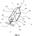
FIG.3 is a schematic axonometric view of the interaction between abucket 4 and the unloading means 6 in proximity of anunloading area 3; -
FIG.4 is a schematic axonometric view of a line L for moving heavy and/or abrasive material through abucket elevator 1 and with a plurality ofunloading areas 3; -
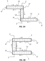
FIG.5A is a schematic view of a Z-shaped configuration of thebucket elevator 1; -
FIG.5B is a schematic view of a C-shaped configuration of thebucket elevator 1; -
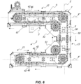
FIG. 6 is an axial sectional schematic view of abucket elevator 1 with asingle unloading area 3; -
FIG. 7 is an exploded axonometric schematic view of abucket 4; -
FIG. 8 is an axonometric schematic view of abucket 4; -
FIG. 9A is a lateral schematic view of some coupledbuckets 4 wherein theconnection edge 42 rests against thesupport edge 41, regarding whichFIG. 9B is a cross-sectional view along the plane A-A andFIG. 9C a cross-sectional view along the plane B-B; -
FIG. 9D is an enlarged view of a detail ofFIG. 9C ; -
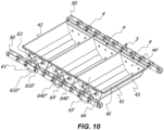
FIG. 10 is an axonometric view of somebuckets 4 coupled to thechains 50. - With reference to the aforementioned figures, herein described is a low
maintenance bucket elevator 1 for moving heavy and/or abrasive materials. - Generally, the heavy and/or abrasive material to be moved may for example be marble, quartz, silica or the like. However, it is clear that the
bucket elevator 1 in question may also be used for moving light materials, for example light food products such as pasta, seeds, legumes, dry fruits or the like, and possibly even abrasive, such as for example light food products characterised by a high percentage of salt, in particular fine salt, such as for example potato chips covered with salt and the like, without departing from the scope of protection of the attached claims. - Although in the description hereinafter reference will be made to moving a heavy and/or abrasive material, it is however clear that there may also be moved a combination or a mixture of heavy and/or abrasive materials, without departing from the scope of protection of the attached claims.
- In addition, all the characteristics mentioned with particular reference to the heavy and/or abrasive material may refer to light materials, possibly even abrasive, without departing from the scope of protection of the attached claims.
- Furthermore, the
bucket elevator 1 may be suitably sized and configured to move the heavy and/or abrasive material from a first lower height to a second higher height following a determined path. - Generally, the
bucket elevator 1 may comprise a plurality ofbuckets 4, which may be designed to convey the heavy and/or abrasive material to be moved. - In greater detail, each
bucket 4 may extend along a longitudinal axis T and it may define aprism structure 40. - The latter may also include a
bottom wall 45 and fourside walls compartment 47 accessible by an opening 48 as shown inFIG. 2 . - In particular, the
walls walls walls 44, 44' may also be mutually faced and lie on incident planes with respect to a transversal axis U, the latter substantially perpendicular with respect to the axis T. - However, it is clear that the
walls walls 44, 44' may lie on planes parallel to the axis U without departing from the scope of protection of the attached claims. - In this manner, the
compartment 47 may therefore be designed to house the material to be moved. - Advantageously, the use of a plurality of
buckets 4 may allow to minimise the relative movement of the heavy and/or abrasive material and - as a result - maintain both the composition and microgranularity thereof, given that the containment in thecompartment 47 limits the possible jerky and/or translatory movement thereof. - Furthermore, the
buckets 4 may be suitably sized to contain a determined amount of material, for example at least 40 kg, preferably 40 - 50 kg. - For example, the
walls - In this manner, this will therefore also allow to change the capacity of the
bucket elevator 1 in question, depending on the type of material conveyed and the type of path to be travelled through. - Generally, the
bucket elevator 1 may comprise aloading area 2 at the lower height where thebuckets 4 may be loaded with the material to be moved. - However, it is clear that the
bucket elevator 1 may also comprise a plurality ofareas 2 for loading thebuckets 4 with the material to be moved without departing from the scope of protection of the attached claims. - For example, the
buckets 4 may be loaded using a vibrating screening machine or the like and/or conveyor belts, arranged at theloading area 2 and suitably configured to unload the precise amount of material in eachbucket 4 so as to have a homogeneous and constant distribution of the product on the buckets. - However, it is clear that the
buckets 4 may be also loaded manually without departing from the scope of protection of the attached claims. - Subsequently, the
bucket elevator 1 may comprise anunloading area 3 at the higher height, for unloading the material moved by thebuckets 4. - Preferably, there may also be provided for a plurality of
areas 3 for unloading the moved material, so as to increase the versatility of thebucket elevator 1. - Advantageously, the
unloading areas 3 may therefore actually be arranged at the points where one desires to unload the moved material. - Other advantages of this particular aspect of the invention will be clearer in the description below.
- However, it is clear that, although in the description hereinafter reference will be made to a
bucket elevator 1 with asingle loading area 2 and a plurality ofunloading areas 3, there may be provided formultiple loading areas 2 and/or asingle unloading area 3 or a plurality thereof without departing from the scope of protection of the attached claims. - By way of example, the
buckets 4 may further unload the material within one or more hoppers: the latter may therefore be suitably sized and arranged at eachunloading area 3 to allow to collect the material therein. - Generally, the
bucket elevator 1 may comprise suitable movement means 5 which may therefore be operatively connected with thebuckets 4 to allow the movement thereof between theloading area 2 and theunloading areas 3. - This means that the
buckets 4 may be moved from theloading area 2 to theunloading areas 3 following a predetermined path to allow the unloading of the moved material. - After unloading the moved heavy and/or abrasive material, the emptied
buckets 4 may therefore be moved from theunloading areas 3 to theloading area 2 following a complementary path so as to be filled with the material to be moved once again. - Generally, the
bucket elevator 1 may further comprise asupport structure 7 which may be self-supporting and preferably made of metal material, adapted to confer structural unity to thebucket elevator 1. - Advantageously, the
support structure 7 may also allow to increase the safety and protection level of possible operators in the working area of thebucket elevator 1. - The
bucket elevator 1 may also further comprise an outer support structure suitably sized to confer further structural stability to thebucket elevator 1 and therefore ensure greater safety, further minimising any vibrations both due to the size of thebucket elevator 1 and the high loads moved by the same. - In particular, the
bucket elevator 1 may define aportion 11 for advancing thebuckets 4 along an axis X' and aportion 12 for advancing along an axis X". - In greater detail, the
advancement portion 11 may be at theloading area 2, while theadvancement portion 12 may be at theunloading area 3. - According to a preferred aspect of the invention, the
unloading areas 3 may be consecutive and arranged at pre-established distances along the axis X' of theadvancement portion 12. - Therefore, this will allow to obtain a multiple
unloading bucket elevator 1 that is small in size and particularly versatile. - Furthermore, the
bucket elevator 1 may also comprise aportion 13 for advancing along an axis Z, the latter interposed between theadvancement portion 11 and theadvancement portion 12, as shown inFIGS. 4 ,5A and 5B . - For example, the
portion 11 may extend for 10 - 12 m, theportion 12 may extend for 25 - 30 m, while theportion 13 may extend for 10 - 12 m. - Thanks to the presence of the
advancement portion 13, theadvancement portion 11 andadvancement portion 12 may therefore be mutually spaced apart. - Furthermore, according to a preferred but not exclusive embodiment, the axes X' and X" respectively of the
advancement portion 11 and of theadvancement portion 12 may be substantially parallel. - In addition, the axis Z may be perpendicular to the axes X' and X" respectively of the
advancement portion 11 and of theadvancement portion 12. - For example, this means that the
advancement portion 13 may extend vertically with respect to theadvancement portion 11 and theadvancement portion 12, which may instead extend horizontally. - However, it is clear that the axis Z may also not be perpendicular to the axes X' and X", that is the
third advancement portion 13 may extend obliquely with respect to thefirst advancement portion 11 and to thesecond advancement portion 12, which may however remain substantially parallel to one with respect to the other, without departing from the scope of protection of the attached claims. - According to a first preferred but not exclusive embodiment, the axes X' and X" may have the same direction, where the direction is defined by the advancement direction of the
buckets 4. - In this first case, the
bucket elevator 1 may have a so-called Z-shaped configuration and shown inFIG. 5A . - According to a second preferred but not exclusive embodiment, the axes X' and X" may have substantially opposite direction, where the direction is defined by the advancement direction of the
buckets 4. - In this second case, the
bucket elevator 1 may have a so-called C-shaped configuration and shown inFIG. 5B . - Advantageously, the C-shaped configuration may be used should there arise the need to contain the overall dimensions of the
bucket elevator 1. - Furthermore, according to a preferred but not exclusive embodiment, the movement means 5 may comprise a pair of
chains 50 which are closed and movable along theadvancement portions - In use, the
chains 50 may remain mutually facing each other and spaced apart with respect to the axes X', X" and Z along therespective advancement portions FIG. 4 . - The use of a pair of
chains 50 is particularly advantageous, given that it allows to move considerable loads and further obtain a significant speed for moving thebuckets 4. - In particular, each
bucket 4 may be laterally connected to thechains 50 through suitable connection means 9. - In this manner, the abrasive material will not jeopardise the connection means 9 and the
buckets 4 may be rotatably coupled to the pair ofchains 50. - The rotatable coupling between the
buckets 4 and the pair ofchains 50 may therefore allow the free rotation of thebuckets 4 around the rotation axis thereof, which - in this case - coincides with the longitudinal axis T. - The expression free rotation of the
buckets 4 around the rotation axis thereof T is used to indicate that the rotary movement of eachbucket 4 around the rotation axis thereof T may be independent, at least in theadvancement portion 12 and - as a result - in proximity of theunloading areas 3, from the translation movement imparted by the movement means 5 thereon. - In particular, the rotation axis T of each
bucket 4 will be substantially perpendicular to the axis X" of theadvancement portion 12. - However, it is clear that each bucket may freely rotate around rotation axis T thereof even at the
advancement portion 11 and/or at theadvancement portion 12, without departing from the scope of protection of the attached claims. - The free rotation range of each
bucket 4 may further be by an angle α measuring 100° -150°, preferably 130° - 140° with respect to the plane defined by theadvancement portion 12. - Then, both at the initial sections and at the final sections of the
advancement portion 11 and of theadvancement portion 12 there may be provided for a pair ofpinions 51 coupled to a drive shaft. - Each
pinion 51 may therefore be peripherally coupled with therespective chain 50 to allow the movement thereof and therefore also thebuckets 4. - Subsequently, the
bucket elevator 1 may further comprise suitable unloading means 6 adapted to allow the unloading of thebuckets 4 at theunloading areas 3. - To this end, the unloading means 6 may therefore be arranged at each unloading
area 3. - In greater detail, the aforementioned unloading means 6 may therefore act on the
buckets 4 to allow the rotation thereof around the respective rotation axis T and the ensuing unloading of the material at the one ormore unloading areas 3, as will be clearer in the description hereinafter. - Furthermore, the
bucket elevator 1 may also comprise suitable control means 8, which may act on the unloading means 6 and be suitably configured to allow the selective unloading of thebuckets 4 at the one ormore unloading areas 3. - The expression selective unloading of the
buckets 4 is used to indicate that the material moved by thebucket 4 may therefore be unloaded by way of response to a command imparted by the control means 8 and therefore only in theunloading areas 3 which were selected by the latter. - This means that the control means 8 may select one or
more unloading areas 3 and therefore act on the respective unloading means 6 for unloading thebuckets 4 in the selectedunloading areas 3. - It is therefore clear that the
buckets 4 will not be unloaded at theunloading areas 3 which were not selected by the control means 8. - As a matter of fact, thanks to the interdependence between the rotation motion around the rotation axis T of each
bucket 4 and the translation motion thereof along theadvancement portion 13, the unloading means 6 selected by the control means 8 may act on thebuckets 4 at theunloading areas 3 of interest therefore so as to allow the unloading thereof. - Advantageously, the control means 8 may further be configured to control the advancement of the movement means 5.
- In particular, the unloading means 6 may comprise one or
more abutment elements 61 and one ormore counteracting elements 62, which may be suitably shaped and mutually interact to allow the rotation of thebuckets 4 around the rotation axis thereof T at the one or moreselected unloading areas 3. - According to a preferred but not exclusive embodiment, the
support structure 7 may comprise one ormore counteracting elements 62, while thebuckets 4 may comprise one ormore abutment elements 61. - However, it is clear that even the opposite may occur, that is the
support structure 7 may comprise the one ormore abutment elements 61, while thebuckets 4 may comprise the one ormore counteracting elements 62, without departing from the scope of protection of the attached claims. - Furthermore, the unloading means 6 may also comprise pairs of
abutment elements 61 and pairs of counteractingelements 62, mutually spaced apart with respect to the axis X" of theadvancement portion 12, without departing from the scope of protection of the attached claims. - In particular, each
bucket 4 may comprise one or more suitablyshaped cam elements 61', which may define the one ormore abutment elements 61, while thesupport structure 7 may comprise one or more pivots 62', which may define the one ormore counteracting elements 62. - According to a preferred but not exclusive embodiment, there may be provided for a
single cam element 61' integrally joined withrespective bucket 4 and in particular it may be mounted on the connection means 9. - The pivots 62' may further be movable between a retracted position and an extended position along a direction perpendicular to the axis X" of the
advancement portion 12. - When the pivot 62' will be in the extended position, it may actually interact with the
cam elements 61' of thebuckets 4 when the latter are at anunloading area 3, as shown inFIG. 3 . - In this manner, the
cam element 61' of thebuckets 4 may actually abut against the pivot 62' arranged at theunloading area 3 of interest. - Following the interaction with the pivot 62', the
cam element 61' may therefore rotate around the axis T of thebucket 4 switching from an initial inoperative position to a maximum rotation position. - Due to the fact that the
cam element 61' is integrally joined with therespective bucket 4, even the latter may - as a result - rotate around the rotation axis T. - The profile of the
cam element 61' may be such to allow a maximum rotation of thebucket 4 in an angular range α between 100° -150°, preferably 130° -140° with respect to the plane defined by theadvancement portion 12, an angular range measured between the latter and the edge area of thebucket 4 as particularly shown inFIG. 6 . - The interaction between the pivot 62' and the
cam profile 61', will therefore allow to unload the material at the one ormore unloading areas 3 of interest. - As a result, once the
bucket 4 will have unloaded the material, thecam profile 61' may rotate in the opposite direction to return to the initial inoperative position thereof. - On the contrary, should the pivot 62' be in the retracted position at an
unloading area 3, the cam profiles 61' of thebuckets 4 may therefore not interact with the latter and therefore thebuckets 4 may not unload the moved material at theunloading area 3. - Preferably, the connection means 9 may further include at least one
interface element 63 and at least one pair of fixingelements 64' and 64". - In a preferred but non-exclusive embodiment, the
interface element 63 may be substantially T-shaped. - Specifically, the
interface element 63 may be coupled to at least oneside wall 44 and/or 44', while the fixingelements 64' and 64" may be obtained on theinterface element 63 or they may be coupled with the latter in a longitudinal direction so as to be mutually superimposed. - In particular, the element 64' may be positioned above the
element 64". - Furthermore, the
cam 61' may be removably coupled withsuch elements 64' and 64". - Even more specifically, the
cam 61' may have aportion 610" removably fixed to theelement 64" and a portion 610' prismatically coupled to the element 64'. - In a preferred but non-exclusive embodiment, the
elements 64' and 64" may be substantially cylindrical. - In particular, the element 64' may have a portion 640' with a first diameter coupled with the
interface 63 and anopposite portion 640" having a diameter smaller than the first. - On the other hand, the portion 610' of the
cam 61' may include anopening 6100 counter-shaped with respect to the portion 640', that is it may have a substantially circular or arc-shaped base with a circumference having diameter substantially equal to the diameter of the portion 640'. - In this manner, the opening
walls 6100 may be in contact with at least one part of the outer surface of the portion 640'. - The
portion 610" may instead be removably fixed to theelement 64" in a per se known manner for example using ascrew 6400 or the like. - Should there arise the need to carry out a maintenance operation on the
cam 61' it will be possible to disassemble only the latter without removing thebucket 4 from thechains 50, therefore removing thefastening screw 6400 of theelement 610" as well as bringing theopening 6100 at theportion 640" therefore remove thecam 61' below. - Advantageously, the control means 8 may be suitably configured to selectively act on the pivots 62' and to move them from the retracted position to the extended position to enable the
unloading area 3 and vice versa to disable it. - To this end, the control means 8 may include one or more solenoid valves or pneumatic valves or any electric actuation device suitably connected with the pivots 62' to move them from the retracted position to the extended position and vice versa.
- Preferably, the control means 8 may also comprise a special control software, which is preprogrammed or which can be set by an operator from an operator's panel.
- In this manner, the control means 8 may therefore allow to select the
unloading areas 3 of interest in which thebuckets 4 may subsequently unload the moved heavy and/or abrasive material. - Advantageously, the control means 8 may also be suitably configured to select a fixed
safety unloading area 3, so as to ensure - in any case - the unloading of the material from thebuckets 4 at the latter. - In this manner, this will therefore allow to prevent the return of the buckets 4 - still full - to the
loading area 2. - Due to the presence of a fixed
safety unloading area 3, thebuckets 4 may actually unload the moved material and therefore return - empty - to theloading area 2 so as to be once again loaded with material to be moved. - Furthermore, it is clear that there may also be provided for a plurality of fixed
safety unloading areas 3, without departing from the scope of protection of the attached claims. - According to a preferred but not exclusive embodiment, each
bucket 4 may further comprise asupport edge 41 and aconnection edge 42, respectively arranged long the edge of thewall FIGS. 1 and 2 . - The
support edge 41 and theconnection edge 42 may therefore be faced and mutually spaced apart with respect to the axis T. - Advantageously, the
connection edge 42 of afirst bucket 4 may be suitably shaped to be mutually superimposed to thesupport edge 41 of a secondconsecutive bucket 4, when both thefirst bucket 4 cand thesecond bucket 4 are in theportion 11 or in theportion 12, to allow the stable connection between thebuckets 4. - In particular, the expression stable connection is used to indicate that the
buckets 4 may be constrained to each other and therefore they may move integrally joined in the same movement direction. - More precisely, the superimposition of the
connection edge 42 of abucket 4 on thesupport edge 41 of aconsecutive bucket 4, and therefore the stable connection between them, may occur when the axes U of thebuckets 4 are substantially coincident, or particularly at theloading area 2 and/or at theunloading areas 3, as shown inFIGS. 1 and4 . - Specifically, the
connection edge 42 may rest againstsupport edge 41 at theportion 11, in particular at theloading area 2. - On the other hand, the
support edge 41 may rest against theconnection edge 42 at theportion 12. - However, it is clear that the
connection edge 42 may rest against thesupport edge 41 even at theportion 12 and therefore at theunloading area 3 or only at the latter and vice versa, that is thesupport edge 41 may rest against theconnection edge 42 even at theportion 11 or only at the latter without departing from the scope of protection of the attached claims. - Therefore, it is clear that, both on the
third portion 13 and on the areas interested by thepinions 51, thebuckets 4 will not have the substantially coincident axes U and therefore they will not be stably connected to each other. - Advantageously, the superimposition of the
connection edge 42 of abucket 4 on thesupport edge 41 of asubsequent bucket 4 may allow to prevent the abrasion thereof and therefore extend the useful life of thebuckets 4. - In addition, the
connection edge 42 may further have a suitably shaped profile and, preferably, a sloping profile. - More precisely, the sloping profile of the
connection edge 42 of thebuckets 4 may therefore define an angle β between 45° - 70°, preferably between 50° - 65° as particularly shown inFIG. 9D , defined between theconnection edge 42 and thewall 43'. - However, it is clear that the
connection edge 42 may have any suitably shaped profile, provided that it allows the stable connection of thebuckets 4 at the one ormore loading 2 and unloading 3 areas, without departing from the scope of protection of the attached claims. - Advantageously, the sloping profile of the
connection edge 42 may therefore allow to minimise the deposition and the resulting stagnation of any material thereon, in particular if the heavy and/or abrasive material - both when thebuckets 4 are loaded with the material to be moved and possibly when they unload the moved material - respectively at the one or more loading and unloading areas. - Advantageously, there may also be provided for means for cleaning the connection edges 42, for example brushes or the like, positioned at the
area 2 for loading thebuckets 4. - The special means for cleaning the connection edges 42 of the
buckets 4 may therefore mechanically remove the material therefrom. - The material removed from a
bucket 4 may therefore be collected in abucket 4 adjacent thereto. - It is however clear that the removed material may be collected below the
structure 7 of thebucket elevator 1 and therefore be recovered subsequently without departing from the scope of protection of the attached claims. - This will therefore allow to minimise the waste material and the possible dispersion of the moved material, with ensuing increase in efficiency of the
bucket elevator 1. - Possibly, the
support structure 7 of thebucket elevator 1 may be substantially open and comprise a plurality of removable parts, to facilitate the detection of problems and malfunctions of thebucket elevator 1. - Advantageously, should there arise the need to carry out routine or even extraordinary maintenance, it will therefore be possible to remove the removable parts of the
bucket elevator 1, when the latter is switched off, so as to be able to access the interested area more easily and without having to disassemble theentire support structure 7. - Therefore, this solution allows to significantly reduce the time required for routine and extraordinary maintenance of the
bucket elevator 1, with a resulting reduction of machine downtime and increase in the overall efficiency thereof. - In a preferred but non-exclusive embodiment, each
bucket 4 may then comprise alongitudinal reinforcement bar 46 preferably positioned in proximity of theconnection edge 42 and integrally joined with thebucket 4, as shown inFIG. 2 . - However, it is clear that the
longitudinal reinforcement bar 46 may also be positioned in another point of thebucket 4 without departing from the scope of protection of the attached claims. - By way of example, it may be possibly positioned on the
bottom wall 45, to lower the barycentre of thebucket 4 and confer - as a result - greater stability to the latter during the movement and the loading/unloading. - Furthermore, it is clear that each
bucket 4 may include one or more reinforcement bars 46 positioned in several points thereof, for example one ormore bars 46 positioned in proximity of theconnection edge 42 and/or one ormore bars 46 positioned on thebottom wall 45 and/or one ormore bars 46 positioned in any other point of thebucket 4. - Furthermore, the presence of the one or more longitudinal reinforcement bars 46 will allow to increase the torsional strength of the bucket and - as a result - the useful life thereof.
- To this end, the one or more longitudinal reinforcement bars 46 may for example be made of steel.
- Advantageously, in an embodiment particularly shown in
FIGS. 6 to 10 , eachbucket 4 may include areinforcement bar 46 integrally joined withconnection edge 42. - In this case, the
reinforcement bar 46 may include a portion 460' integrally joined with theside wall 43' of thebucket 4 and aportion 460" integrally joined with theconnection edge 42. - The
portion 460" and theconnection edge 42 may therefore defining a substantially V-shaped configuration which may allow to define the above-mentioned sloping profile of theconnection edge 42 to minimise the deposition and stagnation of material thereon. - It is therefore clear that besides the
connection edge 42, also theportion 460" may interact with thesupport edge 41 and in particular theportion 460" may rest on the latter at theportions 11 and/or 12 mentioned above. - On the other hand, the portion 460' may contribute to prevent the above-mentioned torsions due to the large dimensions of the
bucket 4 as well as the weight of the conveyed material. - Preferably, from a construction point of view, the
connection edge 42 and thebar 46 may be obtained starting from asingle metal lip 4246 whose folding may define theedge 42, theportions 460' and 460". - To this end, there may be obtained
suitable grooves 4200 between the area defining theedge 42 and theportion 460" to facilitate the folding thereof. - Subsequently, the
grooves 4200 may be welded in a per se known manner, just like the portion 460' to integrally join it to thewall 43'. - According to a further aspect of the invention, each
pinion 51 may further be modular and therefore consist of a defined number of sectors. - In a preferred but non-exclusive embodiment, each
pinion 51 may be made with three pieces which can be assembled and disassembled with respect to each other. - This means that should one or more sectors of the
pinion 51 be damaged, it would therefore be possible to replace only the damaged sectors thereof, hence saving economically. - According to a further aspect of the invention, the drive shafts may be removable from the
support structure 7 due to the presence of a plurality of removable parts, should there be a malfunction or should the latter be damaged. - Furthermore, there may be also provided for sensors, such as for example accelerometers, strain gauges, or load cells, for constantly monitoring the moving components and therefore allow a predictive maintenance thereof.
- To this end, they may be actually positioned at the
support structure 7 and/or at the modular pinions and/or at the movement means 5, to monitor the mechanical stresses and therefore detect possible malfunctions and/or failures. - According to a further aspect of the invention, there may also be provided for a line L for moving the heavy and/or abrasive material to be moved, which may therefore consecutively comprise:
- loading means MC adapted to load the heavy and/or abrasive material to be moved at the one or
more loading areas 2, such as for example vibrating screening machines or the like, which can be suitably configured to load the buckets with a predetermined uniform and constant amount of heavy and/or abrasive material; - a
bucket elevator 1 for moving the heavy and/or abrasive material from one ormore loading areas 2 arranged at the first height to the plurality of unloadingareas 3 arranged at the second height, the latter raised with respect to the first height, as described above; - unloading means MS arranged at the one or
more unloading areas 3, such as for example hoppers or the like which may convey the heavy and/or abrasive material on multiple conveyor belts NT, arranged at each unloadingarea 3. - In particular, the conveyor belts NT may extend along an axis Y incident or at most perpendicular to the axis X" of the
second portion 12 for advancing thebucket elevator 1. - Advantageously, the presence of multiple conveyor belts NT in proximity of the
unloading areas 3 of thebucket elevator 1 may therefore allow to separate the heavy and/or abrasive material, which may be stored or subjected to possible subsequent processes. - Therefore, this will allow to obtain a line L for moving heavy and/or abrasive material that is particularly efficient and/or versatile.
- Preferably, there may be provided for one or more anti-contamination elements for identifying contaminants in the moved heavy and/or abrasive material.
- The presence of contaminants in the heavy and/or abrasive material could actually be significantly harmful if subjected to further processes downstream of the line L.
- Advantageously, it will be possible to position the one or more anti-contamination elements at the second unloading means MS to identify possible contaminants.
- For example, should there arise the need to detect the presence of ferrous or generally ferromagnetic material in the heavy and/or abrasive material, it will be possible to position one or more de-ironing filters or the like at the second unloading means MS, for example in the hoppers, to intercept them and - as a result - remove them from the heavy and/or abrasive material by electromagnetic separation.
- However, it is clear that there may also be present other types of anti-contamination means depending on the type and size of the contaminants present in the heavy and/or abrasive material, without departing from the scope of protection of the attached claims.
- In a further aspect of the invention, irrespective of the above, there may be considered a
bucket 4 for a bucket elevator as described above, having the above-mentionedbottom wall 45,side walls compartment 47 accessible from anopening 48,support edge 41,connection edge 42 and one or more reinforcement bars 46. - Specifically, the latter may include all the characteristics specifically described above.
- According to a further aspect of the invention, there may be provided for a method of use of the
bucket elevator 1 for moving the heavy and/or abrasive material, for example marble, quartz, silica or the like, from a first lower height to a second higher height. - Basically, the
buckets 4 may be filled with the heavy and/or abrasive material to be moved at theloading area 2. - The step for loading the
buckets 4 may be carried out automatically, using vibrating screening machines or the like, or even manually, through an operator designated to load thebuckets 4 with the heavy and/or abrasive material. - Subsequently, there may be provided for a step for selecting one or
more unloading areas 3 using the control means 8. - Such selection may therefore be carried out from an operator's panel through a dedicated software.
- In particular, the control means 8 may act on the unloading means 6 so as to move the pivots 62' arranged at the selected unloading means 3 from the retracted position to the extended position.
- By so doing, the pivots 62' in extended position may therefore cooperate with the cam profiles 61' of the
buckets 4 to allow the latter to unload the heavy and/or abrasive material at the selectedunloading areas 3. - Subsequently to the step for selecting the
unloading areas 3, thebuckets 4 filled with the heavy and/or abrasive material may therefore be moved usingmeans 5 for moving from the loading area 2 - arranged at the lower height - until the one or moreselected unloading areas 3 arranged at the higher height. - In proximity of the
unloading areas 3 of interest, thebuckets 4 may therefore selectively unload the heavy and/or abrasive material in the one or moreselected unloading areas 3. - Such method of use may further be implemented to be carried out iteratively.
- The method of use thus described has the particular advantage of being easy to implement and particularly reliable, thanks to the use of a dedicated software.
- Therefore, the operator will only have to act from an operator's panel positioned in proximity of the working area, with resulting increase in the safety level of the
bucket elevator 1. -
Such bucket elevator 1 is also particularly efficient from an energy point of view, given that it allows to move significant volumes of heavy and/or abrasive material at a considerable movement speed, with ensuing increase in the nominal capacity and in the overall efficiency of thebucket elevator 1. - In the light of the above, the present invention attains the pre-established objects.
- Furthermore, it is clear that the present invention may include various parts and/or similar or identical elements. Unless otherwise specified, similar or identical parts and/or elements will be indicated using a single reference number, it being clear that the described technical characteristics are common to all similar or identical parts and/or elements.
- The invention is susceptible to modifications and variants, all falling within the scope of protection of the attached claims. All details can be replaced by other technically equivalent elements, and the materials can be different depending on the needs, without departing from the scope of protection of the invention defined by the attached claims.
Claims (13)
- A bucket elevator for moving heavy and/or abrasive material, for example marble, quartz, silica or the like, from a first lower height to a second higher height superimposed to the first, comprising:- a plurality of buckets (4) suitably sized and configured to convey the heavy and/or abrasive material;- at least one area (2) for loading each bucket of said plurality of buckets (4) with the heavy and/or abrasive material to be moved arranged at said first lower height;- at least one area (3) for unloading the moved heavy and/or abrasive material arranged at said second higher height;- means (5) for moving said plurality of buckets (4) operatively connected therewith and suitably configured to move the latter between said at least one loading area (2) and said at least one unloading area (3), the movement means (5) including a first advancement portion (11) at said at least one loading area (2) and a second advancement portion (12) defining a first axis (X") at said at least one unloading area (3), the buckets (4) further being free to rotate around a second axis (T) substantially perpendicular to said first axis (X") at least at said at least one unloading area (3);- unloading means (6) arranged at said at least one unloading area (3) and acting on the buckets (4) to allow the rotation thereof around said second axis (T) so as to unload said heavy and/or abrasive material at the at least one unloading area (3).
- Bucket elevator according to the preceding claim, comprising a plurality of unloading areas (3) mutually consecutive along said first axis (X").
- Bucket elevator according to the preceding claim, further comprising control means (8) acting on said unloading means (6) suitably configured to allow the selective unloading of the heavy and/or abrasive material at at least one unloading area (3) selected from said plurality of unloading areas (3).
- Bucket elevator according to the preceding claim, wherein said movement means (5) comprise at least one pair of chains (50) movable along said first portion (11) and second portion (12) mutually faced, the chains (50) being rotatably connected with the buckets (4) of said plurality of buckets (4) to facilitate the free rotation of the latter at least around said second axis (T) in an angular range (α) preferably measuring 100° - 150°.
- Bucket elevator according to one or more of the preceding claims, further comprising a support structure (7) which includes said at least one unloading area (3), said unloading means (6) comprising at least one abutment element (61) and at least one counteracting element (62) mutually interacting and shaped to allow the rotation of the buckets (4) around said second axis (T) at said at least one unloading area (3), one of said support structure (7) and said buckets (4) including said abutment element (61), the other of said support structure (7) and said buckets (4) including said counteracting element (62).
- Bucket elevator according to claims 3 and 5 or 4 and 5, wherein said buckets (4) include at least one cam element (61') defining said abutment element (61), said support structure (7) including at least one pivot (62') which can be moved between an extended position and a retracted position along an axis parallel to said first axis (X") and defining said at least one abutment element (62), said control means (8) acting on the at least one pivot (62') arranged at the unloading area (3) selected from said plurality of unloading areas (3), to move it from the retracted position to the extended position so as to allow the interaction thereof with said at least one cam element (61').
- Bucket elevator according to any of the preceding claims, wherein each bucket of said plurality of buckets (4) includes at least one support edge (41) and a connection edge (42) facing each other with respect to said second axis (T) and spaced along a direction perpendicular to the latter, said connection edge (42) of a first bucket (4) being mutually superimposed with respect to said support edge (41) of a second bucket (4) at least at one of said first and one second advancement portion (11, 12) to facilitate the stable connection between them respectively at said at least one loading area (2) and said at least one unloading area (3), said connection edge (42) preferably having a sloping profile suitably shaped to prevent the deposit of heavy and/or abrasive material thereon.
- Bucket elevator according to the preceding claim, wherein said connection edge (42) rests on said support edge (41) at least at said at least one loading area (2) of said first portion (11) for preventing the deposition of heavy and/or abrasive material on the connection edge (42).
- Bucket elevator according to claim 7 or 8, wherein each bucket of said plurality of buckets (4) includes at least one longitudinal reinforcement bar (46) positioned in proximity of said connection edge (42) integrally joined with the bucket (4).
- Bucket elevator according to the preceding claim, wherein each bucket of said plurality of buckets (4) includes at least one side wall (43') extending substantially parallel to said second axis (T), said connection edge (42) extending along the edge of the latter and being spaced therefrom by a predetermined angle (β), said at least one reinforcement bar (46) including at least one first portion (460') integrally joined with said at least one side wall (43') and a second portion (460") mutually integrally joined with said connection edge (42), said second portion (460") and said connection edge (42) defining a substantially V-shaped configuration.
- Bucket elevator according to any one of the preceding claims, wherein said first portion (11) defines a third axis (X') substantially parallel to said first axis (X") and mutually spaced therefrom, said advancement means (5) further comprising a third advancement portion (13) interposed between said first and second portion (11, 12) and defining a fourth axis (Z) substantially perpendicular to said first and third axis (X", X').
- A line (L) for moving heavy and/or abrasive material by means of a bucket elevator (1), consecutively comprising:- means (MC) for loading the heavy and/or abrasive material to be moved arranged at the at least one loading area (2);- said bucket elevator (1) according to one or more of claims 2 to 11 when depending on 2;- second means (MS) for unloading the heavy and/or abrasive material moved arranged at said plurality of unloading areas (3), the same comprising a plurality of conveyor belts (NT) each at each unloading area (3), each defining a fifth axis (Y) substantially incident with respect to said first axis (X").
- Method of use of a bucket elevator (1) for moving heavy and/or abrasive material, for example marble, quartz, silica or the like, from a first lower height to a second higher height superimposed to the first, comprising consecutively and iteratively the steps of:- loading the heavy and/or abrasive material to be moved in at least one loading area (2) of said bucket elevator (1) according to one or more of claims 3 to 11 when depending on 3;- selecting at least one unloading area (3) between said plurality of unloading areas (3) by said control means (8);- moving the heavy and/or abrasive material from said at least one loading area (2) to said at least one selected unloading area (3);- selective unloading of the heavy and/or abrasive material by actuating said first unloading means (6) by said control means (8) for unloading the heavy and/or abrasive material moved in said at least one unloading area (3) selected from said plurality of unloading areas (3).
Applications Claiming Priority (1)
| Application Number | Priority Date | Filing Date | Title |
|---|---|---|---|
| IT102022000013552A IT202200013552A1 (en) | 2022-06-27 | 2022-06-27 | LOW MAINTENANCE BUCKET ELEVATOR FOR HANDLING HEAVY AND/OR ABRASIVE MATERIAL, AS WELL AS LINE FOR HANDLING HEAVY AND/OR ABRASIVE MATERIAL AND METHOD OF USE OF THE BUCKET ELEVATOR |
Publications (2)
| Publication Number | Publication Date |
|---|---|
| EP4299480A1 true EP4299480A1 (en) | 2024-01-03 |
| EP4299480B1 EP4299480B1 (en) | 2026-02-04 |
Family
ID=83188490
Family Applications (1)
| Application Number | Title | Priority Date | Filing Date |
|---|---|---|---|
| EP23181894.9A Active EP4299480B1 (en) | 2022-06-27 | 2023-06-27 | Low maintenance bucket elevator for moving heavy and/or abrasive material, as well as line for moving heavy and/or abrasive material and method of use of the bucket elevator |
Country Status (2)
| Country | Link |
|---|---|
| EP (1) | EP4299480B1 (en) |
| IT (1) | IT202200013552A1 (en) |
Citations (4)
| Publication number | Priority date | Publication date | Assignee | Title |
|---|---|---|---|---|
| DE3728881A1 (en) * | 1987-08-29 | 1989-03-16 | Nerak Foerdertechnik | Bucket for a bucket conveyor |
| US4972934A (en) * | 1988-08-11 | 1990-11-27 | Meyer Machine Company | Bucket distribution system |
| US20040094390A1 (en) * | 2002-05-06 | 2004-05-20 | Universal Industries, Inc. | Bucket elevator conveyors |
| EP3892571A1 (en) * | 2020-04-07 | 2021-10-13 | Jose Borrell S.A. | Reversible bucket elevator |
-
2022
- 2022-06-27 IT IT102022000013552A patent/IT202200013552A1/en unknown
-
2023
- 2023-06-27 EP EP23181894.9A patent/EP4299480B1/en active Active
Patent Citations (4)
| Publication number | Priority date | Publication date | Assignee | Title |
|---|---|---|---|---|
| DE3728881A1 (en) * | 1987-08-29 | 1989-03-16 | Nerak Foerdertechnik | Bucket for a bucket conveyor |
| US4972934A (en) * | 1988-08-11 | 1990-11-27 | Meyer Machine Company | Bucket distribution system |
| US20040094390A1 (en) * | 2002-05-06 | 2004-05-20 | Universal Industries, Inc. | Bucket elevator conveyors |
| EP3892571A1 (en) * | 2020-04-07 | 2021-10-13 | Jose Borrell S.A. | Reversible bucket elevator |
Also Published As
| Publication number | Publication date |
|---|---|
| EP4299480B1 (en) | 2026-02-04 |
| IT202200013552A1 (en) | 2023-12-27 |
Similar Documents
| Publication | Publication Date | Title |
|---|---|---|
| RU2139231C1 (en) | Device for conveyor transportation of products with simultaneously sorting them for preset parameters | |
| JP5876403B2 (en) | Fruit and vegetable conveying method and fruit and vegetable conveying device | |
| CA1151610A (en) | System to fill the cases in a uniform manner with fruit and vegetables | |
| WO2008027303A2 (en) | Continuous bulk bag discharging facility | |
| Taher et al. | Automation of material handling with bucket elevator and belt conveyor | |
| US4003462A (en) | Log sorting system | |
| EP4299480B1 (en) | Low maintenance bucket elevator for moving heavy and/or abrasive material, as well as line for moving heavy and/or abrasive material and method of use of the bucket elevator | |
| CN105707224A (en) | Nondestructive grain discharge and cleaning device | |
| Kumar | Fundamentals of conveyors | |
| KR101826884B1 (en) | Hermetic type magnetic separator | |
| KR101596929B1 (en) | Fruit sorting machine | |
| KR102743248B1 (en) | Sorting apparatus of fruits and vegetables | |
| CN107243453A (en) | A kind of sieving equipment with conveying function | |
| CN109867106B (en) | Combined conveyor belt with automatic identification system | |
| JP5850991B1 (en) | Waste sorting machine | |
| KR20250010823A (en) | Electronic weight selecting table system for group packing | |
| US6065482A (en) | Non-linear chain belt type conveyor | |
| CN217076052U (en) | Reposition of redundant personnel conveyor | |
| US3288312A (en) | Method and apparatus for the sorting, collecting and stacking of sheet materials | |
| CN216888725U (en) | Automatic recovery unit of blanking of continuous ship unloaders | |
| CN110304404A (en) | A multi-point chain bucket conveyor | |
| Farzana et al. | Handling and transportation of food grains | |
| US3145937A (en) | Apparatus for conveying and separating material | |
| CN113428607A (en) | Automatic recovery unit of blanking of continuous ship unloaders | |
| CN207170231U (en) | A kind of sieving equipment with conveying function |
Legal Events
| Date | Code | Title | Description |
|---|---|---|---|
| PUAI | Public reference made under article 153(3) epc to a published international application that has entered the european phase |
Free format text: ORIGINAL CODE: 0009012 |
|
| STAA | Information on the status of an ep patent application or granted ep patent |
Free format text: STATUS: THE APPLICATION HAS BEEN PUBLISHED |
|
| AK | Designated contracting states |
Kind code of ref document: A1 Designated state(s): AL AT BE BG CH CY CZ DE DK EE ES FI FR GB GR HR HU IE IS IT LI LT LU LV MC ME MK MT NL NO PL PT RO RS SE SI SK SM TR |
|
| STAA | Information on the status of an ep patent application or granted ep patent |
Free format text: STATUS: REQUEST FOR EXAMINATION WAS MADE |
|
| 17P | Request for examination filed |
Effective date: 20240626 |
|
| RBV | Designated contracting states (corrected) |
Designated state(s): AL AT BE BG CH CY CZ DE DK EE ES FI FR GB GR HR HU IE IS IT LI LT LU LV MC ME MK MT NL NO PL PT RO RS SE SI SK SM TR |
|
| GRAP | Despatch of communication of intention to grant a patent |
Free format text: ORIGINAL CODE: EPIDOSNIGR1 |
|
| STAA | Information on the status of an ep patent application or granted ep patent |
Free format text: STATUS: GRANT OF PATENT IS INTENDED |
|
| INTG | Intention to grant announced |
Effective date: 20250930 |
|
| GRAS | Grant fee paid |
Free format text: ORIGINAL CODE: EPIDOSNIGR3 |
|
| GRAA | (expected) grant |
Free format text: ORIGINAL CODE: 0009210 |
|
| STAA | Information on the status of an ep patent application or granted ep patent |
Free format text: STATUS: THE PATENT HAS BEEN GRANTED |
|
| P01 | Opt-out of the competence of the unified patent court (upc) registered |
Free format text: CASE NUMBER: UPC_APP_0014595_4299480/2025 Effective date: 20251125 |
|
| AK | Designated contracting states |
Kind code of ref document: B1 Designated state(s): AL AT BE BG CH CY CZ DE DK EE ES FI FR GB GR HR HU IE IS IT LI LT LU LV MC ME MK MT NL NO PL PT RO RS SE SI SK SM TR |
|
| REG | Reference to a national code |
Ref country code: CH Ref legal event code: F10 Free format text: ST27 STATUS EVENT CODE: U-0-0-F10-F00 (AS PROVIDED BY THE NATIONAL OFFICE) Effective date: 20260204 Ref country code: GB Ref legal event code: FG4D |
|
| REG | Reference to a national code |
Ref country code: IE Ref legal event code: FG4D |
|
| REG | Reference to a national code |
Ref country code: DE Ref legal event code: R096 Ref document number: 602023011490 Country of ref document: DE |