EP4299398A1 - Vehicle, load distribution recognition method and apparatus therefor, medium, and electronic device - Google Patents
Vehicle, load distribution recognition method and apparatus therefor, medium, and electronic device Download PDFInfo
- Publication number
- EP4299398A1 EP4299398A1 EP22827337.1A EP22827337A EP4299398A1 EP 4299398 A1 EP4299398 A1 EP 4299398A1 EP 22827337 A EP22827337 A EP 22827337A EP 4299398 A1 EP4299398 A1 EP 4299398A1
- Authority
- EP
- European Patent Office
- Prior art keywords
- vehicle
- pitch angle
- driving force
- load distribution
- actual
- Prior art date
- Legal status (The legal status is an assumption and is not a legal conclusion. Google has not performed a legal analysis and makes no representation as to the accuracy of the status listed.)
- Pending
Links
- 238000000034 method Methods 0.000 title claims abstract description 32
- 230000001133 acceleration Effects 0.000 claims abstract description 60
- 239000000725 suspension Substances 0.000 claims abstract description 41
- 238000004364 calculation method Methods 0.000 claims description 18
- 238000004590 computer program Methods 0.000 claims description 12
- 238000010586 diagram Methods 0.000 description 12
- 230000005484 gravity Effects 0.000 description 4
- 238000005259 measurement Methods 0.000 description 4
- 238000006243 chemical reaction Methods 0.000 description 3
- 238000005516 engineering process Methods 0.000 description 3
- 230000006870 function Effects 0.000 description 3
- 238000005096 rolling process Methods 0.000 description 3
- 230000005540 biological transmission Effects 0.000 description 2
- 239000000463 material Substances 0.000 description 2
- 238000001228 spectrum Methods 0.000 description 2
- 230000003068 static effect Effects 0.000 description 2
- 238000004891 communication Methods 0.000 description 1
- 238000002474 experimental method Methods 0.000 description 1
- 230000014509 gene expression Effects 0.000 description 1
- 238000009434 installation Methods 0.000 description 1
- 238000012986 modification Methods 0.000 description 1
- 230000004048 modification Effects 0.000 description 1
- 238000012544 monitoring process Methods 0.000 description 1
- 239000013307 optical fiber Substances 0.000 description 1
- 238000012545 processing Methods 0.000 description 1
Images


Classifications
-
- B—PERFORMING OPERATIONS; TRANSPORTING
- B60—VEHICLES IN GENERAL
- B60W—CONJOINT CONTROL OF VEHICLE SUB-UNITS OF DIFFERENT TYPE OR DIFFERENT FUNCTION; CONTROL SYSTEMS SPECIALLY ADAPTED FOR HYBRID VEHICLES; ROAD VEHICLE DRIVE CONTROL SYSTEMS FOR PURPOSES NOT RELATED TO THE CONTROL OF A PARTICULAR SUB-UNIT
- B60W40/00—Estimation or calculation of non-directly measurable driving parameters for road vehicle drive control systems not related to the control of a particular sub unit, e.g. by using mathematical models
- B60W40/12—Estimation or calculation of non-directly measurable driving parameters for road vehicle drive control systems not related to the control of a particular sub unit, e.g. by using mathematical models related to parameters of the vehicle itself, e.g. tyre models
- B60W40/13—Load or weight
-
- B—PERFORMING OPERATIONS; TRANSPORTING
- B60—VEHICLES IN GENERAL
- B60G—VEHICLE SUSPENSION ARRANGEMENTS
- B60G17/00—Resilient suspensions having means for adjusting the spring or vibration-damper characteristics, for regulating the distance between a supporting surface and a sprung part of vehicle or for locking suspension during use to meet varying vehicular or surface conditions, e.g. due to speed or load
- B60G17/015—Resilient suspensions having means for adjusting the spring or vibration-damper characteristics, for regulating the distance between a supporting surface and a sprung part of vehicle or for locking suspension during use to meet varying vehicular or surface conditions, e.g. due to speed or load the regulating means comprising electric or electronic elements
- B60G17/018—Resilient suspensions having means for adjusting the spring or vibration-damper characteristics, for regulating the distance between a supporting surface and a sprung part of vehicle or for locking suspension during use to meet varying vehicular or surface conditions, e.g. due to speed or load the regulating means comprising electric or electronic elements characterised by the use of a specific signal treatment or control method
- B60G17/0182—Resilient suspensions having means for adjusting the spring or vibration-damper characteristics, for regulating the distance between a supporting surface and a sprung part of vehicle or for locking suspension during use to meet varying vehicular or surface conditions, e.g. due to speed or load the regulating means comprising electric or electronic elements characterised by the use of a specific signal treatment or control method involving parameter estimation, e.g. observer, Kalman filter
-
- B—PERFORMING OPERATIONS; TRANSPORTING
- B60—VEHICLES IN GENERAL
- B60W—CONJOINT CONTROL OF VEHICLE SUB-UNITS OF DIFFERENT TYPE OR DIFFERENT FUNCTION; CONTROL SYSTEMS SPECIALLY ADAPTED FOR HYBRID VEHICLES; ROAD VEHICLE DRIVE CONTROL SYSTEMS FOR PURPOSES NOT RELATED TO THE CONTROL OF A PARTICULAR SUB-UNIT
- B60W40/00—Estimation or calculation of non-directly measurable driving parameters for road vehicle drive control systems not related to the control of a particular sub unit, e.g. by using mathematical models
- B60W40/10—Estimation or calculation of non-directly measurable driving parameters for road vehicle drive control systems not related to the control of a particular sub unit, e.g. by using mathematical models related to vehicle motion
- B60W40/105—Speed
-
- B—PERFORMING OPERATIONS; TRANSPORTING
- B60—VEHICLES IN GENERAL
- B60W—CONJOINT CONTROL OF VEHICLE SUB-UNITS OF DIFFERENT TYPE OR DIFFERENT FUNCTION; CONTROL SYSTEMS SPECIALLY ADAPTED FOR HYBRID VEHICLES; ROAD VEHICLE DRIVE CONTROL SYSTEMS FOR PURPOSES NOT RELATED TO THE CONTROL OF A PARTICULAR SUB-UNIT
- B60W40/00—Estimation or calculation of non-directly measurable driving parameters for road vehicle drive control systems not related to the control of a particular sub unit, e.g. by using mathematical models
- B60W40/10—Estimation or calculation of non-directly measurable driving parameters for road vehicle drive control systems not related to the control of a particular sub unit, e.g. by using mathematical models related to vehicle motion
- B60W40/107—Longitudinal acceleration
-
- B—PERFORMING OPERATIONS; TRANSPORTING
- B60—VEHICLES IN GENERAL
- B60W—CONJOINT CONTROL OF VEHICLE SUB-UNITS OF DIFFERENT TYPE OR DIFFERENT FUNCTION; CONTROL SYSTEMS SPECIALLY ADAPTED FOR HYBRID VEHICLES; ROAD VEHICLE DRIVE CONTROL SYSTEMS FOR PURPOSES NOT RELATED TO THE CONTROL OF A PARTICULAR SUB-UNIT
- B60W40/00—Estimation or calculation of non-directly measurable driving parameters for road vehicle drive control systems not related to the control of a particular sub unit, e.g. by using mathematical models
- B60W40/10—Estimation or calculation of non-directly measurable driving parameters for road vehicle drive control systems not related to the control of a particular sub unit, e.g. by using mathematical models related to vehicle motion
- B60W40/11—Pitch movement
-
- B—PERFORMING OPERATIONS; TRANSPORTING
- B60—VEHICLES IN GENERAL
- B60G—VEHICLE SUSPENSION ARRANGEMENTS
- B60G2400/00—Indexing codes relating to detected, measured or calculated conditions or factors
- B60G2400/05—Attitude
- B60G2400/051—Angle
- B60G2400/0512—Pitch angle
-
- B—PERFORMING OPERATIONS; TRANSPORTING
- B60—VEHICLES IN GENERAL
- B60G—VEHICLE SUSPENSION ARRANGEMENTS
- B60G2400/00—Indexing codes relating to detected, measured or calculated conditions or factors
- B60G2400/10—Acceleration; Deceleration
- B60G2400/106—Acceleration; Deceleration longitudinal with regard to vehicle, e.g. braking
-
- B—PERFORMING OPERATIONS; TRANSPORTING
- B60—VEHICLES IN GENERAL
- B60G—VEHICLE SUSPENSION ARRANGEMENTS
- B60G2400/00—Indexing codes relating to detected, measured or calculated conditions or factors
- B60G2400/20—Speed
- B60G2400/204—Vehicle speed
-
- B—PERFORMING OPERATIONS; TRANSPORTING
- B60—VEHICLES IN GENERAL
- B60G—VEHICLE SUSPENSION ARRANGEMENTS
- B60G2400/00—Indexing codes relating to detected, measured or calculated conditions or factors
- B60G2400/30—Propulsion unit conditions
-
- B—PERFORMING OPERATIONS; TRANSPORTING
- B60—VEHICLES IN GENERAL
- B60G—VEHICLE SUSPENSION ARRANGEMENTS
- B60G2400/00—Indexing codes relating to detected, measured or calculated conditions or factors
- B60G2400/60—Load
- B60G2400/61—Load distribution
-
- B—PERFORMING OPERATIONS; TRANSPORTING
- B60—VEHICLES IN GENERAL
- B60W—CONJOINT CONTROL OF VEHICLE SUB-UNITS OF DIFFERENT TYPE OR DIFFERENT FUNCTION; CONTROL SYSTEMS SPECIALLY ADAPTED FOR HYBRID VEHICLES; ROAD VEHICLE DRIVE CONTROL SYSTEMS FOR PURPOSES NOT RELATED TO THE CONTROL OF A PARTICULAR SUB-UNIT
- B60W40/00—Estimation or calculation of non-directly measurable driving parameters for road vehicle drive control systems not related to the control of a particular sub unit, e.g. by using mathematical models
- B60W40/12—Estimation or calculation of non-directly measurable driving parameters for road vehicle drive control systems not related to the control of a particular sub unit, e.g. by using mathematical models related to parameters of the vehicle itself, e.g. tyre models
- B60W40/13—Load or weight
- B60W2040/1307—Load distribution on each wheel suspension
-
- B—PERFORMING OPERATIONS; TRANSPORTING
- B60—VEHICLES IN GENERAL
- B60W—CONJOINT CONTROL OF VEHICLE SUB-UNITS OF DIFFERENT TYPE OR DIFFERENT FUNCTION; CONTROL SYSTEMS SPECIALLY ADAPTED FOR HYBRID VEHICLES; ROAD VEHICLE DRIVE CONTROL SYSTEMS FOR PURPOSES NOT RELATED TO THE CONTROL OF A PARTICULAR SUB-UNIT
- B60W40/00—Estimation or calculation of non-directly measurable driving parameters for road vehicle drive control systems not related to the control of a particular sub unit, e.g. by using mathematical models
- B60W40/12—Estimation or calculation of non-directly measurable driving parameters for road vehicle drive control systems not related to the control of a particular sub unit, e.g. by using mathematical models related to parameters of the vehicle itself, e.g. tyre models
- B60W40/13—Load or weight
- B60W2040/1315—Location of the centre of gravity
-
- B—PERFORMING OPERATIONS; TRANSPORTING
- B60—VEHICLES IN GENERAL
- B60W—CONJOINT CONTROL OF VEHICLE SUB-UNITS OF DIFFERENT TYPE OR DIFFERENT FUNCTION; CONTROL SYSTEMS SPECIALLY ADAPTED FOR HYBRID VEHICLES; ROAD VEHICLE DRIVE CONTROL SYSTEMS FOR PURPOSES NOT RELATED TO THE CONTROL OF A PARTICULAR SUB-UNIT
- B60W2520/00—Input parameters relating to overall vehicle dynamics
- B60W2520/10—Longitudinal speed
- B60W2520/105—Longitudinal acceleration
-
- B—PERFORMING OPERATIONS; TRANSPORTING
- B60—VEHICLES IN GENERAL
- B60W—CONJOINT CONTROL OF VEHICLE SUB-UNITS OF DIFFERENT TYPE OR DIFFERENT FUNCTION; CONTROL SYSTEMS SPECIALLY ADAPTED FOR HYBRID VEHICLES; ROAD VEHICLE DRIVE CONTROL SYSTEMS FOR PURPOSES NOT RELATED TO THE CONTROL OF A PARTICULAR SUB-UNIT
- B60W2520/00—Input parameters relating to overall vehicle dynamics
- B60W2520/16—Pitch
-
- B—PERFORMING OPERATIONS; TRANSPORTING
- B60—VEHICLES IN GENERAL
- B60W—CONJOINT CONTROL OF VEHICLE SUB-UNITS OF DIFFERENT TYPE OR DIFFERENT FUNCTION; CONTROL SYSTEMS SPECIALLY ADAPTED FOR HYBRID VEHICLES; ROAD VEHICLE DRIVE CONTROL SYSTEMS FOR PURPOSES NOT RELATED TO THE CONTROL OF A PARTICULAR SUB-UNIT
- B60W2530/00—Input parameters relating to vehicle conditions or values, not covered by groups B60W2510/00 or B60W2520/00
- B60W2530/10—Weight
Definitions
- the present disclosure relates to the technical field of vehicles, and specifically to a vehicle and a vehicle load distribution identification method and apparatus, and a medium and electronic device.
- a load sensor or at least two body height sensors At the suspension.
- the wheel speed signal that may come from the wheel speed sensor of the antilock braking system.
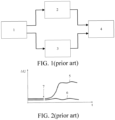
- the wheel speed signals of the front and rear wheels are analyzed in terms of frequency spectrum, and in 4, the resonance energies are compared and the load distribution is estimated.
- Fig. 2 shows the case where the resonance energy varies with the load in an example.
- 5 represents the resonance energy characteristic value (resonance energy/resonance frequency) of the rear axle
- 6 represents the resonance energy characteristic value of the front axle.
- the load of the rear axle of the vehicle is increased at 7, and then increase of the characteristic value is detected, thus identifying the change of load distribution.
- this technology needs to identify the resonance spectrum characteristics of the front and rear wheels, which involves a large amount of calculation, and the rear wheels of most front-wheel-drive vehicle models lack apparent resonance characteristics (or the apparent resonance characteristics can only be identified in some vehicle speed segments), so the corresponding resonance energy characteristic values cannot be obtained. Therefore, this technology has a rather limited application range.
- an objective of the present disclosure is to provide a vehicle load distribution identification method to reduce the cost of vehicle load distribution identification and extend the application range.
- a second objective of the present disclosure is to provide a vehicle load distribution identification apparatus.
- a third objective of the present disclosure is to provide a computer-readable storage medium.
- a fourth objective of the present disclosure is to provide an electronic device.
- a fifth objective of the present disclosure is to provide a vehicle.
- an embodiment in a first aspect of the present disclosure provides a vehicle load distribution identification method including the steps of: acquiring a speed and longitudinal acceleration of the vehicle; acquiring an actual driving force of the vehicle when the longitudinal acceleration is less than an acceleration threshold; obtaining an actual pitch angle of the vehicle according to the actual driving force and the vehicle speed; and obtaining load distribution of the vehicle according to the actual pitch angle.
- the obtaining the actual pitch angle of the vehicle according to the actual driving force and the vehicle speed includes: obtaining a reference driving force corresponding to the vehicle speed according to the vehicle speed and acquiring a reference pitch angle; and obtaining the actual pitch angle according to the actual driving force, the reference driving force and the reference pitch angle.
- the obtaining the actual pitch angle according to the actual driving force, the reference driving force and the reference pitch angle includes: calculating an average of a plurality of the actual driving forces to obtain an average driving force; calculating a second difference between the reference driving force and the average driving force; acquiring the mass of the vehicle and calculating a second ratio of the second difference to the mass; and summing the second ratio with the reference pitch angle to obtain the actual pitch angle.
- the obtaining load distribution of the vehicle according to the actual pitch angle includes: acquiring a front-rear wheelbase, the stiffness of a front suspension and the stiffness of a rear suspension of the vehicle; and calculating the load distribution of the vehicle according to the actual pitch angle, the front-rear wheelbase, the stiffness of the front suspension and the stiffness of the rear suspension.
- an embodiment in a second aspect of the present disclosure provides a vehicle load distribution identification apparatus, including: a first acquisition module configured to acquire a speed and longitudinal acceleration of the vehicle; a second acquisition module configured to acquire an actual driving force of the vehicle when the longitudinal acceleration is less than an acceleration threshold; a calculation module configured to obtain an actual pitch angle of the vehicle according to the actual driving force and the vehicle speed; and an identification module configured to obtain load distribution of the vehicle according to the actual pitch angle.
- an embodiment in a third aspect of the present disclosure provides a computer-readable storage medium having a computer program stored thereon, where when executed by a processor, the computer program implements the vehicle load distribution identification method described above.
- an embodiment in a fourth aspect of the present disclosure provides an electronic device, including a memory and a processor, the memory having a computer program stored thereon. When executed by the processor, the computer program implements the vehicle load distribution identification method described above.
- an embodiment in a fifth embodiment of the present disclosure provides a vehicle including the vehicle load distribution identification apparatus according to the embodiment described above or the electronic device according to the embodiment described above.
- the difference between the front and rear axle loads of the vehicle can be identified by calculating the pitch angle of the vehicle, so that the vehicle load distribution can be identified without installing dedicated sensors such as a load sensor and a vehicle body height sensor at the vehicle suspension, which reduces the cost of vehicle load distribution identification and allows a wide range of applications without being limited by the vehicle model.
- the front axle load F 1 and the rear axle load F 2 are applied to the front and rear suspensions respectively, which changes the height of the suspensions, thus causing the change of the pitch angle.
- the difference between the front axle load and the rear axle load can be estimated according to the change of the pitch angle.
- Fig. 6 shows the measurement of the acceleration sensor versus the actual longitudinal acceleration of the vehicle.
- the acceleration sensor 70 is fixed on the vehicle body 80, so its levelness in the longitudinal direction (vehicle traveling direction) is affected jointly by the pitch angle and the road slope.
- ⁇ is the longitudinal included angle between the inertia component of the acceleration sensor and the horizontal plane
- the road slope angle is i
- the pitch angle of the vehicle is ⁇
- a s 0 ⁇ F t , 2
- a s 0 mg .
- Fig. 3 is a flowchart of a vehicle load distribution identification method according to an embodiment of the present disclosure.
- the model of correspondence between the load distribution and the reference driving force F 0 and the reference pitch angle ⁇ 0 needs to be calibrated.
- the reference driving force F 0 and the reference pitch angle ⁇ 0 can be calibrated when the vehicle is in a state with a known load distribution.
- a time interval can be set, and when the vehicle is controlled to run at various vehicle speeds, the acceleration sensor 10 acquires the longitudinal acceleration at the set time interval.
- a driving force statistical calculation module 30 (which may be a recursive least square RLS, Kalman filter or other filters) calculates the driving force corresponding to the longitudinal acceleration measurement (approximation) less than the acceleration threshold, and the driving force can be obtained by multiplying the torque output by the power source (the driving motor of the vehicle) by the speed ratio of the transmission system; Then it can calculate the average of the driving forces to obtain the reference driving force corresponding to each vehicle speed.
- N driving forces can be selected to calculate the average, where N is an integer greater than 1 and may assume a value of 3, 4, 5, etc.
- the acceleration threshold can be calibrated according to experiments, and the acceleration threshold can be different for different vehicle models.
- the reference driving force F 0 output by the driving force statistical calculation module 30 can be stored in different units of the storage module 40 divided based on the vehicle speeds according to the current vehicle speed. Meanwhile, the reference pitch angle data ⁇ 0 calculated (or directly measured) according to the current load distribution can also be stored in the storage module 40.
- the vehicle load distribution identification method includes the following steps.
- the longitudinal acceleration a s of the vehicle can be collected by the acceleration sensor 10 shown in 4, and the vehicle speed can be collected by the vehicle speed sensor, where both the acceleration sensor and the vehicle speed sensor can be installed on the vehicle body.
- the vehicle speed can also be calculated based on the wheel speed of the vehicle, and the wheel speed can be collected by the wheel speed sensor installed on the wheel.
- the acceleration sensor 10 can collect the longitudinal acceleration a s at a certain time interval.
- the driving force statistical calculation module 30 can calculate the actual driving force corresponding to the longitudinal acceleration a s less than the acceleration threshold, and the actual driving force can be specifically calculated by multiplying the torque output by the driving motor of the vehicle by the speed ratio of the transmission system. Specifically, the actual driving force of the vehicle can be acquired once every time it is determined that the longitudinal acceleration is less than the acceleration threshold.
- the obtaining the actual pitch angle of the vehicle according to the actual driving force and the vehicle speed can include: obtaining the corresponding reference driving force according to the vehicle speed and acquiring the reference pitch angle; and obtaining the actual pitch angle according to the actual driving force, the reference driving force and the reference pitch angle.
- the preset value can be calibrated as required.
- the obtaining the actual pitch angle according to the actual driving force, the reference driving force and the reference pitch angle can include: calculating a difference between the reference driving force and the actual driving force; acquiring the mass of the vehicle and calculating a ratio of the difference to the mass; and summing the ratio with the reference pitch angle to obtain the actual pitch angle.
- the obtaining the actual pitch angle according to the actual driving force, the reference driving force and the reference pitch angle can also include: calculating an average of multiple actual driving forces to obtain an average driving force; calculating a difference between the reference driving force and the average driving force; acquiring the mass of the vehicle and calculating a ratio of the difference to the mass; and summing the ratio with the reference pitch angle to obtain the actual pitch angle.
- the average driving force can be calculated within a certain period of time. For example, counting is started when it is determined that the longitudinal acceleration is less than the acceleration threshold, and the longitudinal acceleration is continuously monitored. If all the longitudinal accelerations are less than the acceleration threshold within a preset time, or the proportion of the longitudinal accelerations less than the acceleration threshold is greater than a certain value, the average of all the actual driving forces obtained within the preset time is calculated to obtain the average driving force.
- the average driving force can also be calculated by statistically counting the number of the actual driving forces. For example, every time it is determined that the longitudinal acceleration is less than the acceleration threshold, an actual driving force is obtained. When the number of the actual driving forces reaches a preset value, the average of the preset number of actual driving forces is calculated to obtain the average driving force.
- the driving force statistical calculation module 30 can further calculate the average of the actual driving forces F x .
- the obtaining the load distribution of the vehicle according to the actual pitch angle can include: acquiring a front-rear wheelbase, the stiffness of a front suspension and the stiffness of a rear suspension of the vehicle; and calculating the load distribution of the vehicle according to the actual pitch angle, the front-rear wheelbase, the stiffness of the front suspension and the stiffness of the rear suspension.
- the load distribution meter module 60 can calculate the front-rear load distribution of the vehicle according to the actual pitch angle ⁇ output by the pitch angle calculation module 50 and the pre-stored vehicle information (including the front-rear wheelbase, the stiffness of the front suspension and the stiffness of the rear suspension).
- the obtained static load distribution of the front and rear axles of the vehicle can be used to improve the performance of the following systems: the Antilock Brake System (ABS), the Electronic Stability Program (ESP), the Traction Control System (TCS), the Electric Brakeforce Distribution (EBD), the active suspension Active Body Control (ABC), Anti Rolling Program (ARP), headlight range control, tire pressure monitoring, and the like.
- ABS Antilock Brake System
- ESP Electronic Stability Program
- TCS Traction Control System
- ESD Electric Brakeforce Distribution
- ABSC Active suspension Active Body Control
- ARP Anti Rolling Program
- headlight range control tire pressure monitoring, and the like.
- the vehicle load is not directly measured, instead, the pitch angle of the vehicle is estimated and then the difference between the front axle and rear axle loads can be calculated according to the statics knowledge.
- the vehicle load distribution can be identified without installing dedicated sensors such as a load sensor and a vehicle body height sensor at the vehicle suspension, which reduces the cost of vehicle load distribution identification and allows a wide range of applications without being limited by the vehicle model.
- Fig. 7 is a structural block diagram of a vehicle load distribution identification apparatus according to an embodiment of the present disclosure.
- the vehicle load distribution identification apparatus 100 includes: a first acquisition module 110, a second acquisition module 120, a calculation module 130 and an identification module 140.
- the first acquisition module 110 is configured to acquire a speed and longitudinal acceleration of the vehicle; the second acquisition module 120 is configured to acquire, through statistical calculation, an actual driving force of the vehicle when the longitudinal acceleration is less than an acceleration threshold; the calculation module 130 is configured to obtain an actual pitch angle of the vehicle according to the actual driving force and vehicle speed; and the identification module 140 is configured to obtain load distribution of the vehicle according to the actual pitch angle.
- the calculation module 130 is specifically configured to: when the number of actual driving forces acquired by the second acquisition module 120 reaches a preset value, calculate the average of the preset number of actual driving forces to obtain the average driving force; obtain the corresponding reference driving force according to the vehicle speed and obtain a reference pitch angle; and obtain the actual pitch angle according to the average driving force, the reference driving force and the reference pitch angle.
- the calculation module 130 is specifically configured to, in obtaining the actual pitch angle according to the average driving force and the reference driving force: calculate a difference between the reference driving force and the average driving force; acquire the mass of the vehicle and calculating a ratio of the difference to the mass; and summing the ratio with the reference pitch angle to obtain the actual pitch angle.
- the identification module 140 is specifically configured to: acquire a front-rear wheelbase, the stiffness of a front suspension and the stiffness of a rear suspension of the vehicle; and calculate the load distribution of the vehicle according to the actual pitch angle, the front-rear wheelbase, the stiffness of the front suspension and the stiffness of the rear suspension.
- the vehicle load distribution identification apparatus 100 can be identified without installing dedicated sensors such as a load sensor and a vehicle body height sensor at the vehicle suspension, which reduces the cost of vehicle load distribution identification and allows a wide range of applications without being limited by the vehicle model .
- the present disclosure provides a computer-readable storage medium.
- the computer-readable storage medium has a computer program stored thereon, which, when executed by a processor, implements the vehicle load distribution identification method described above.
- the vehicle load distribution can be identified without installing dedicated sensors such as a load sensor and a vehicle body height sensor at the vehicle suspension, which reduces the cost of vehicle load distribution identification and allows a wide range of applications without being limited by the vehicle model.
- the present disclosure further provides an electronic device.
- the electronic device 200 includes a memory 210 and a processor 220.
- the memory 210 has a computer program 230 stored thereon, which, when executed by the processor 220, implements the vehicle load distribution identification method described above.
- the vehicle load distribution can be identified without installing dedicated sensors such as a load sensor and a vehicle body height sensor at the vehicle suspension, which reduces the cost of vehicle load distribution identification and allows a wide range of applications without being limited by the vehicle model.
- Fig. 9 is a structural block diagram of a vehicle according to an embodiment of the present disclosure.
- the vehicle 1000 includes the vehicle load distribution identification apparatus 100 according to the embodiment described above.
- Fig. 10 is a structural block diagram of a vehicle according to another embodiment of the present disclosure.
- the vehicle 1000 includes the electronic device 200 according to the embodiment described above.
- the load distribution identification apparatus 100 or the electronic device 200 described above by use of the load distribution identification apparatus 100 or the electronic device 200 described above, it is not necessary to install dedicated sensors such as a load sensor and a vehicle body height sensor at the vehicle suspension, which reduces the cost of vehicle load distribution identification and allows a wide range of applications without being limited by the vehicle model.
- the term "computer-readable medium” may be any apparatus that can contain, store, communicate, propagate, or transmit programs to be used by the instruction execution system, apparatus or device or to be used in combination with such instruction execution systems, apparatuses or devices. More specific examples (a non-exhaustive list) of the computer-readable medium include: an electrical connection part (electronic device) having one or more wires, a portable computer diskette (magnetic apparatus), a random access memory (RAM), a read-only memory (ROM), an erasable programmable read-only memory (EPROM or flash memory), an optical fiber apparatus, and a portable compact disk read-only memory (CDROM).
- an electrical connection part electronic device having one or more wires
- a portable computer diskette magnetic apparatus
- RAM random access memory
- ROM read-only memory
- EPROM or flash memory erasable programmable read-only memory
- CDROM portable compact disk read-only memory
- the computer-readable medium can even be paper or other suitable media on which the program can be printed, because the program can be obtained electronically by, for example, optically scanning the paper or other media, then editing, interpreting, or processing in other suitable ways if necessary, and then storing it in a computer memory.
- various parts of the present disclosure can be implemented in hardware, software, firmware, or a combination thereof.
- multiple steps or methods may be implemented by using software or firmware that are stored in a memory and executed by a proper instruction execution system.
- implementation may be realized by any one of the following technologies well known in the art or a combination thereof: a discrete logic circuit including a logic gate circuit for implementing a logic function for a data signal, a dedicated integrated circuit including a proper combined logic gate circuit, a programmable gate array (PGA), a field programmable gate array (FPGA), and the like.
- references term such as "an embodiment,” “some embodiments,” “an example,” “a specific example,” or “some examples” means that a specific feature, structure, material, or characteristic that is described with reference to the embodiment or the example is included in at least one embodiment or example of the present application.
- exemplary expressions of the foregoing terms do not necessarily refer to the same embodiment or example.
- the described specific features, structures, materials, or characteristics may be combined in a proper manner in any one or more of the embodiments or examples.
- orientation or position relations indicated by the terms such as “center”, “longitudinal”, “transverse”, “length”, “width”, “thickness”, “above”, “below”, “front”, “back”, “left”, “right”, “vertical”, “horizontal”, “top”, “bottom”, “inside”, “outside”, “clockwise”, “anticlockwise”, “axial direction”, “radial direction”, and “circumferential direction” are based on orientation or position relations shown in the drawings, and are used merely for ease and brevity of illustration and description, rather than indicating or implying that the mentioned apparatus or element must have a particular orientation or must be constructed and operated in a particular orientation. Therefore, such terms should not be construed as limitation of the present disclosure.
- first and second are used merely for the purpose of description, and shall not be construed as indicating or implying relative importance or implying a quantity of indicated technical features. Therefore, a feature defined by the term “first” or “second” may explicitly indicate or implicitly include at least one of such features.
- the term “multiple” means at least two, such as two and three, unless it is specifically defined otherwise.
- connection may be a fixed connection, a detachable connection, or an integral connection; or the connection may be a mechanical connection or an electrical connection; or the connection may be a direct connection, an indirect connection through an intermediary medium, or internal communication between two elements or mutual reaction relation between two elements, unless otherwise explicitly specified.
- the first feature being located “above” or “below” the second feature may indicate the first feature is in direct contact with the second feature, or the first feature is in indirect contact with the second feature through an intermediary medium.
- the first feature being “above”, “over”, or “on” the second feature may indicate that the first feature is directly above or obliquely above the second feature, or may merely indicate that the horizontal position of the first feature is higher than that of the second feature.
- the first feature being “below”, “under”, and “beneath” the second feature may indicate that the first feature is right below the second feature or obliquely below the second feature, or may merely indicate that the horizontal position of the first feature is lower than that of the second feature.
Landscapes
- Engineering & Computer Science (AREA)
- Mechanical Engineering (AREA)
- Physics & Mathematics (AREA)
- Automation & Control Theory (AREA)
- Mathematical Physics (AREA)
- Transportation (AREA)
- Vehicle Body Suspensions (AREA)
- Control Of Driving Devices And Active Controlling Of Vehicle (AREA)
- Regulating Braking Force (AREA)
- General Factory Administration (AREA)
- Devices For Checking Fares Or Tickets At Control Points (AREA)
Abstract
Description
- This application claims priority to
Chinese Patent Application No.202110687601.4, entitled "VEHICLE AND VEHICLE LOAD DISTRIBUTION IDENTIFICATION METHOD, APPARATUS, MEDIUM AND ELECTRONIC DEVICE" and filed on June 21, 2021 - The present disclosure relates to the technical field of vehicles, and specifically to a vehicle and a vehicle load distribution identification method and apparatus, and a medium and electronic device.
- When measuring the load distribution of the front and rear axles of a vehicle, it is generally necessary to install a load sensor or at least two body height sensors at the suspension. In order to avoid installation of the aforementioned sensors at the suspension, it is proposed in the related art to indirectly estimate the front and rear load levels according to deformation of the tire under different normal loads. Specifically, As shown in
Fig. 1, 1 represents the wheel speed signal that may come from the wheel speed sensor of the antilock braking system. In 2 and 3, the wheel speed signals of the front and rear wheels are analyzed in terms of frequency spectrum, and in 4, the resonance energies are compared and the load distribution is estimated.Fig. 2 shows the case where the resonance energy varies with the load in an example. 5 represents the resonance energy characteristic value (resonance energy/resonance frequency) of the rear axle, and 6 represents the resonance energy characteristic value of the front axle. The load of the rear axle of the vehicle is increased at 7, and then increase of the characteristic value is detected, thus identifying the change of load distribution. - However, this technology needs to identify the resonance spectrum characteristics of the front and rear wheels, which involves a large amount of calculation, and the rear wheels of most front-wheel-drive vehicle models lack apparent resonance characteristics (or the apparent resonance characteristics can only be identified in some vehicle speed segments), so the corresponding resonance energy characteristic values cannot be obtained. Therefore, this technology has a rather limited application range.
- The present disclosure is intended to solve one of technical problems in the related art at least to some extent. In view of this, an objective of the present disclosure is to provide a vehicle load distribution identification method to reduce the cost of vehicle load distribution identification and extend the application range.
- A second objective of the present disclosure is to provide a vehicle load distribution identification apparatus.
- A third objective of the present disclosure is to provide a computer-readable storage medium.
- A fourth objective of the present disclosure is to provide an electronic device.
- A fifth objective of the present disclosure is to provide a vehicle.
- In order to achieve the foregoing objectives, an embodiment in a first aspect of the present disclosure provides a vehicle load distribution identification method including the steps of: acquiring a speed and longitudinal acceleration of the vehicle; acquiring an actual driving force of the vehicle when the longitudinal acceleration is less than an acceleration threshold; obtaining an actual pitch angle of the vehicle according to the actual driving force and the vehicle speed; and obtaining load distribution of the vehicle according to the actual pitch angle.
- According to an embodiment of the present disclosure, the obtaining the actual pitch angle of the vehicle according to the actual driving force and the vehicle speed includes: obtaining a reference driving force corresponding to the vehicle speed according to the vehicle speed and acquiring a reference pitch angle; and obtaining the actual pitch angle according to the actual driving force, the reference driving force and the reference pitch angle.
- According to an embodiment of the present disclosure, the obtaining the actual pitch angle according to the actual driving force, the reference driving force and the reference pitch angle includes: calculating a first difference between the reference driving force and the actual driving force; acquiring the mass of the vehicle and calculating a first ratio of the first difference to the mass; and summing the first ratio with the reference pitch angle to obtain the actual pitch angle.
- According to an embodiment of the present disclosure, the obtaining the actual pitch angle according to the actual driving force, the reference driving force and the reference pitch angle includes: calculating an average of a plurality of the actual driving forces to obtain an average driving force; calculating a second difference between the reference driving force and the average driving force; acquiring the mass of the vehicle and calculating a second ratio of the second difference to the mass; and summing the second ratio with the reference pitch angle to obtain the actual pitch angle.
- According to an embodiment of the present disclosure, the obtaining load distribution of the vehicle according to the actual pitch angle includes: acquiring a front-rear wheelbase, the stiffness of a front suspension and the stiffness of a rear suspension of the vehicle; and calculating the load distribution of the vehicle according to the actual pitch angle, the front-rear wheelbase, the stiffness of the front suspension and the stiffness of the rear suspension.
- According to an embodiment of the present disclosure, the load distribution of the vehicle is calculated by the following equation:

- In order to achieve the foregoing objectives, an embodiment in a second aspect of the present disclosure provides a vehicle load distribution identification apparatus, including: a first acquisition module configured to acquire a speed and longitudinal acceleration of the vehicle; a second acquisition module configured to acquire an actual driving force of the vehicle when the longitudinal acceleration is less than an acceleration threshold; a calculation module configured to obtain an actual pitch angle of the vehicle according to the actual driving force and the vehicle speed; and an identification module configured to obtain load distribution of the vehicle according to the actual pitch angle.
- In order to achieve the foregoing objectives, an embodiment in a third aspect of the present disclosure provides a computer-readable storage medium having a computer program stored thereon, where when executed by a processor, the computer program implements the vehicle load distribution identification method described above.
- In order to achieve the foregoing objectives, an embodiment in a fourth aspect of the present disclosure provides an electronic device, including a memory and a processor, the memory having a computer program stored thereon. When executed by the processor, the computer program implements the vehicle load distribution identification method described above.
- In order to achieve the foregoing objectives, an embodiment in a fifth embodiment of the present disclosure provides a vehicle including the vehicle load distribution identification apparatus according to the embodiment described above or the electronic device according to the embodiment described above.
- With the vehicle and the vehicle load distribution identification method and apparatus and the medium and electronic device according to the embodiments of the present disclosure, the difference between the front and rear axle loads of the vehicle can be identified by calculating the pitch angle of the vehicle, so that the vehicle load distribution can be identified without installing dedicated sensors such as a load sensor and a vehicle body height sensor at the vehicle suspension, which reduces the cost of vehicle load distribution identification and allows a wide range of applications without being limited by the vehicle model.
- Additional aspects and advantages of the present disclosure will partially be given in the following description, and partially become apparent from the following description, or be learned from practices of the present disclosure.
-
-
Fig. 1 is a schematic structural diagram of vehicle load distribution identification in the related art; -
Fig. 2 is a schematic diagram of variation of the resonance energy with the load in the related art; -
Fig. 3 is a flowchart of a vehicle load distribution identification method according to an embodiment of the present disclosure; -
Fig. 4 is a schematic structural diagram of vehicle load distribution identification according to an embodiment of the present disclosure; -
Fig. 5 is a schematic diagram of the pitch angle versus the front and rear axle load of the vehicle according to an embodiment of the present disclosure; -
Fig. 6 is a schematic diagram of the measurement of an acceleration sensor versus the actual longitudinal acceleration of the vehicle according to an embodiment of the present disclosure; -
Fig. 7 is a structural block diagram of a vehicle load distribution identification apparatus according to an embodiment of the present disclosure; -
Fig. 8 is a structural block diagram of an electronic device according to an embodiment of the present disclosure; -
Fig. 9 is a structural block diagram of a vehicle according to an embodiment of the present disclosure; and -
Fig. 10 is a structural block diagram of a vehicle according to another embodiment of the present disclosure. - Embodiments of the present disclosure are described in detail below, and examples of the embodiments are shown in the drawings, where the same or similar elements or the elements having same or similar functions are denoted by the same or similar reference numerals throughout the description. The embodiments described below with reference to the drawings are exemplary and intended to explain the present disclosure, and shall not be construed as limitation of the present disclosure.
- The vehicle and the vehicle load distribution identification method and apparatus and the medium and electronic device according to embodiments of the present disclosure will be described below with reference to
Figs. 3-10 . - First, the principle of vehicle load distribution identification according to the embodiment of the present disclosure will be explained.
- As shown in
Fig. 5 , the front axle load F 1 and the rear axle load F 2 are applied to the front and rear suspensions respectively, which changes the height of the suspensions, thus causing the change of the pitch angle. Based on this principle, the difference between the front axle load and the rear axle load can be estimated according to the change of the pitch angle. - Specifically, the stiffness of the front suspension k 1 the stiffness of the rear suspension k 2 and the front-rear wheelbase L of the vehicle are acquired from the vehicle parameters, so the relation between the front-rear axle loads and the pitch angle θ is:

- As an example, if the stiffnesses of the front and rear suspensions are approximately equal and assumed as k, the pitch angle θ and the difference between the front and rear axle loads ΔF can be simplified as a direct proportion relation:

- Therefore, the difference between the front and rear axle loads can be obtained by estimating the pitch angle.
-
Fig. 6 shows the measurement of the acceleration sensor versus the actual longitudinal acceleration of the vehicle. Referring toFig. 6 , when the vehicle travels on a road 90 with a certain slope, theacceleration sensor 70 is fixed on thevehicle body 80, so its levelness in the longitudinal direction (vehicle traveling direction) is affected jointly by the pitch angle and the road slope. InFig. 6 , α is the longitudinal included angle between the inertia component of the acceleration sensor and the horizontal plane, the road slope angle is i, and the pitch angle of the vehicle is θ, then the relation between the angles is: α = θ + i . - As the acceleration sensor is not kept horizontal, the longitudinal acceleration as measured by it includes the components of the longitudinal acceleration of the vehicle av and the acceleration of gravity in the measurement direction of the sensor: as = av cosθ + g sin α.
- The above equation can be approximated as: as = av + gi + gθ
- The longitudinal dynamic equation during travel of the vehicle is as follows:

where Ft is the driving force, Fw is the air resistance, Ff is the rolling resistance, m is the mass of the vehicle, g is the acceleration of gravity, i is the slope and δ is the conversion coefficient of rotating mass. At a higher gear (lower speed ratio), the conversion coefficient of rotating mass is close to 1. At this time, the longitudinal dynamic equation of the vehicle is simplified as:

- Substituting the acceleration as measured by the acceleration sensor into the above equation, we can obtain:

- When as = 0, we can obtain from the equation above:

- Because the relation between the rolling resistance Ff and the vehicle speed is weak, and the relation between the air resistance Fw and the vehicle speed is approximately quadratic, and its coefficient (that is, the air resistance coefficient) is only related to the shape of the vehicle, the difference in rolling resistance is ignored, and it can be considered that the same vehicle with different loads experiences the same resistance Fw + Ff when the vehicle speed is the same or similar. Therefore, the difference in pitch angle of the same vehicle traveling at the same speed in different load conditions can be calculated by the following equation (where F t,1 is the driving force in
load condition 1 when as = 0 ; and F t,2 is the driving force inload condition 2 when as = 0):

- Based on the foregoing principle, the present disclosure provides a vehicle load distribution identification method.
Fig. 3 is a flowchart of a vehicle load distribution identification method according to an embodiment of the present disclosure. - It should be noted that before performing this vehicle load distribution identification method, the model of correspondence between the load distribution and the reference driving force F 0 and the reference pitch angle θ 0 needs to be calibrated. Specifically, the reference driving force F 0 and the reference pitch angle θ 0 can be calibrated when the vehicle is in a state with a known load distribution.
- Specifically, a time interval can be set, and when the vehicle is controlled to run at various vehicle speeds, the
acceleration sensor 10 acquires the longitudinal acceleration at the set time interval. Then, a driving force statistical calculation module 30 (which may be a recursive least square RLS, Kalman filter or other filters) calculates the driving force corresponding to the longitudinal acceleration measurement (approximation) less than the acceleration threshold, and the driving force can be obtained by multiplying the torque output by the power source (the driving motor of the vehicle) by the speed ratio of the transmission system; Then it can calculate the average of the driving forces to obtain the reference driving force corresponding to each vehicle speed. Optionally, N driving forces can be selected to calculate the average, where N is an integer greater than 1 and may assume a value of 3, 4, 5, etc. The acceleration threshold can be calibrated according to experiments, and the acceleration threshold can be different for different vehicle models. - The reference driving force F 0 output by the driving force
statistical calculation module 30 can be stored in different units of thestorage module 40 divided based on the vehicle speeds according to the current vehicle speed. Meanwhile, the reference pitch angle data θ 0 calculated (or directly measured) according to the current load distribution can also be stored in thestorage module 40. - As shown in
Fig. 3 , the vehicle load distribution identification method includes the following steps. - S31: the speed and longitudinal acceleration of the vehicle are obtained.
- Specifically, the longitudinal acceleration as of the vehicle can be collected by the
acceleration sensor 10 shown in 4, and the vehicle speed can be collected by the vehicle speed sensor, where both the acceleration sensor and the vehicle speed sensor can be installed on the vehicle body. Alternatively, the vehicle speed can also be calculated based on the wheel speed of the vehicle, and the wheel speed can be collected by the wheel speed sensor installed on the wheel. - S32: When the longitudinal acceleration is less than the acceleration threshold, the actual driving force of the vehicle is acquired.
- As a feasible implementation, referring to
Fig. 4 , theacceleration sensor 10 can collect the longitudinal acceleration as at a certain time interval. The driving forcestatistical calculation module 30 can calculate the actual driving force corresponding to the longitudinal acceleration as less than the acceleration threshold, and the actual driving force can be specifically calculated by multiplying the torque output by the driving motor of the vehicle by the speed ratio of the transmission system. Specifically, the actual driving force of the vehicle can be acquired once every time it is determined that the longitudinal acceleration is less than the acceleration threshold. - S33: the actual pitch angle of the vehicle is obtained according to the actual driving force and the vehicle speed.
- As a feasible implementation, the obtaining the actual pitch angle of the vehicle according to the actual driving force and the vehicle speed can include: obtaining the corresponding reference driving force according to the vehicle speed and acquiring the reference pitch angle; and obtaining the actual pitch angle according to the actual driving force, the reference driving force and the reference pitch angle. The preset value can be calibrated as required.
- In this implementation, the obtaining the actual pitch angle according to the actual driving force, the reference driving force and the reference pitch angle can include: calculating a difference between the reference driving force and the actual driving force; acquiring the mass of the vehicle and calculating a ratio of the difference to the mass; and summing the ratio with the reference pitch angle to obtain the actual pitch angle.
- Specifically, referring to
Fig. 4 , the driving forcestatistical calculation module 30 can output the actual driving force to the pitchangle calculation module 50, and the pitchangle calculation module 50 compares the actual driving force F with the reference driving force F 0 corresponding to the current vehicle speed in thestorage module 40 and calculates the actual pitch angle θ of the vehicle according to the following equation:

where θ 0 is the reference pitch angle, which can be obtained from thestorage module 40; m is the mass of the vehicle and g is the acceleration of gravity. - In this implementation, the obtaining the actual pitch angle according to the actual driving force, the reference driving force and the reference pitch angle can also include: calculating an average of multiple actual driving forces to obtain an average driving force; calculating a difference between the reference driving force and the average driving force; acquiring the mass of the vehicle and calculating a ratio of the difference to the mass; and summing the ratio with the reference pitch angle to obtain the actual pitch angle.
- Specifically, the average driving force can be calculated within a certain period of time. For example, counting is started when it is determined that the longitudinal acceleration is less than the acceleration threshold, and the longitudinal acceleration is continuously monitored. If all the longitudinal accelerations are less than the acceleration threshold within a preset time, or the proportion of the longitudinal accelerations less than the acceleration threshold is greater than a certain value, the average of all the actual driving forces obtained within the preset time is calculated to obtain the average driving force. The average driving force can also be calculated by statistically counting the number of the actual driving forces. For example, every time it is determined that the longitudinal acceleration is less than the acceleration threshold, an actual driving force is obtained. When the number of the actual driving forces reaches a preset value, the average of the preset number of actual driving forces is calculated to obtain the average driving force. Referring to
Fig. 4 , after obtaining multiple actual driving forces, the driving forcestatistical calculation module 30 can further calculate the average of the actual driving forces Fx . The pitchangle calculation module 50 compares the average of the driving forces Fx output by the driving forcestatistical calculation module 30 with the reference driving force F 0 corresponding to the current vehicle speed in thestorage module 40, and calculates the actual pitch angle θ of the vehicle according to the following equation:

where θ 0 is the reference pitch angle, which can be obtained from thestorage module 40; m is the mass of the vehicle and g is the acceleration of gravity. - S34: the load distribution of the vehicle is obtained according to the actual pitch angle.
- As a feasible implementation, the obtaining the load distribution of the vehicle according to the actual pitch angle can include: acquiring a front-rear wheelbase, the stiffness of a front suspension and the stiffness of a rear suspension of the vehicle; and calculating the load distribution of the vehicle according to the actual pitch angle, the front-rear wheelbase, the stiffness of the front suspension and the stiffness of the rear suspension.
- Specifically, referring to
Fig. 4 , the loaddistribution meter module 60 can calculate the front-rear load distribution of the vehicle according to the actual pitch angle θ output by the pitchangle calculation module 50 and the pre-stored vehicle information (including the front-rear wheelbase, the stiffness of the front suspension and the stiffness of the rear suspension). Specifically, the load distribution of the vehicle can be calculated by the following equation:

where θ is the actual pitch angle, L is the front-rear wheelbase, k1 ,k2 are respectively the stiffness of the front suspension and the stiffness of the rear suspension, and F 1,F 2 are respectively the front axle load and the rear axle load of the vehicle. - In an embodiment, the obtained static load distribution of the front and rear axles of the vehicle can be used to improve the performance of the following systems: the Antilock Brake System (ABS), the Electronic Stability Program (ESP), the Traction Control System (TCS), the Electric Brakeforce Distribution (EBD), the active suspension Active Body Control (ABC), Anti Rolling Program (ARP), headlight range control, tire pressure monitoring, and the like.
- With the vehicle load distribution identification method according to the embodiment of the present disclosure, the vehicle load is not directly measured, instead, the pitch angle of the vehicle is estimated and then the difference between the front axle and rear axle loads can be calculated according to the statics knowledge. As such, the vehicle load distribution can be identified without installing dedicated sensors such as a load sensor and a vehicle body height sensor at the vehicle suspension, which reduces the cost of vehicle load distribution identification and allows a wide range of applications without being limited by the vehicle model.
-
Fig. 7 is a structural block diagram of a vehicle load distribution identification apparatus according to an embodiment of the present disclosure. - As shown in
Fig. 7 , the vehicle loaddistribution identification apparatus 100 includes: a first acquisition module 110, asecond acquisition module 120, acalculation module 130 and anidentification module 140. - The first acquisition module 110 is configured to acquire a speed and longitudinal acceleration of the vehicle; the
second acquisition module 120 is configured to acquire, through statistical calculation, an actual driving force of the vehicle when the longitudinal acceleration is less than an acceleration threshold; thecalculation module 130 is configured to obtain an actual pitch angle of the vehicle according to the actual driving force and vehicle speed; and theidentification module 140 is configured to obtain load distribution of the vehicle according to the actual pitch angle. - As a feasible implementation, the
calculation module 130 is specifically configured to: when the number of actual driving forces acquired by thesecond acquisition module 120 reaches a preset value, calculate the average of the preset number of actual driving forces to obtain the average driving force; obtain the corresponding reference driving force according to the vehicle speed and obtain a reference pitch angle; and obtain the actual pitch angle according to the average driving force, the reference driving force and the reference pitch angle. - The
calculation module 130 is specifically configured to, in obtaining the actual pitch angle according to the average driving force and the reference driving force: calculate a difference between the reference driving force and the average driving force; acquire the mass of the vehicle and calculating a ratio of the difference to the mass; and summing the ratio with the reference pitch angle to obtain the actual pitch angle. - As a feasible implementation, the
identification module 140 is specifically configured to: acquire a front-rear wheelbase, the stiffness of a front suspension and the stiffness of a rear suspension of the vehicle; and calculate the load distribution of the vehicle according to the actual pitch angle, the front-rear wheelbase, the stiffness of the front suspension and the stiffness of the rear suspension. - Specifically, the load distribution of the vehicle can be calculated by the following equation:

where θ is the actual pitch angle, L is the front-rear wheelbase, k1 ,k2 are respectively the stiffness of the front suspension and the stiffness of the rear suspension, and F1,F 2 are respectively the front axle load and the rear axle load of the vehicle. - It should be noted that, for other specific implementations of the vehicle load
distribution identification apparatus 100 according to the embodiment of the present disclosure, reference may be made to the specific implementations of the vehicle load distribution identification method of the above embodiment of the present disclosure. - With the vehicle load
distribution identification apparatus 100 according to the embodiment of the present disclosure, the vehicle load distribution can be identified without installing dedicated sensors such as a load sensor and a vehicle body height sensor at the vehicle suspension, which reduces the cost of vehicle load distribution identification and allows a wide range of applications without being limited by the vehicle model . - The present disclosure provides a computer-readable storage medium.
- In this embodiment, the computer-readable storage medium has a computer program stored thereon, which, when executed by a processor, implements the vehicle load distribution identification method described above.
- With the computer-readable storage medium according to the embodiment of the present disclosure, when the computer program stored thereon for the vehicle load distribution identification method described above is executed by a processor, the vehicle load distribution can be identified without installing dedicated sensors such as a load sensor and a vehicle body height sensor at the vehicle suspension, which reduces the cost of vehicle load distribution identification and allows a wide range of applications without being limited by the vehicle model.
- In an embodiment, the present disclosure further provides an electronic device.
- In this embodiment, as shown in
Fig. 8 , theelectronic device 200 includes amemory 210 and aprocessor 220. Thememory 210 has acomputer program 230 stored thereon, which, when executed by theprocessor 220, implements the vehicle load distribution identification method described above. - With the
electronic device 200 according to the embodiment of the present disclosure, when thecomputer program 230 stored in thememory 210 thereof for the vehicle load distribution identification method described above is executed by theprocessor 220, the vehicle load distribution can be identified without installing dedicated sensors such as a load sensor and a vehicle body height sensor at the vehicle suspension, which reduces the cost of vehicle load distribution identification and allows a wide range of applications without being limited by the vehicle model. -
Fig. 9 is a structural block diagram of a vehicle according to an embodiment of the present disclosure. - As shown in
Fig. 9 , thevehicle 1000 includes the vehicle loaddistribution identification apparatus 100 according to the embodiment described above. -
Fig. 10 is a structural block diagram of a vehicle according to another embodiment of the present disclosure. - As shown in
Fig. 10 , thevehicle 1000 includes theelectronic device 200 according to the embodiment described above. - With the vehicle according to the embodiment described above, by use of the load
distribution identification apparatus 100 or theelectronic device 200 described above, it is not necessary to install dedicated sensors such as a load sensor and a vehicle body height sensor at the vehicle suspension, which reduces the cost of vehicle load distribution identification and allows a wide range of applications without being limited by the vehicle model. - It should be noted that the logic and/or steps shown in the flowcharts or described in any other manner herein, for example, a sequenced list that may be considered as executable instructions for implementing logical functions, may be embodied in any computer-readable medium to be used by an instruction execution system, apparatus, or device (for example, a computer-based system, a system including a processor, or another system that can fetch an instruction from the instruction execution system, apparatus, or device and execute the instruction) or to be used in combination with such instruction execution systems, apparatuses, or devices. In this specification, the term "computer-readable medium" may be any apparatus that can contain, store, communicate, propagate, or transmit programs to be used by the instruction execution system, apparatus or device or to be used in combination with such instruction execution systems, apparatuses or devices. More specific examples (a non-exhaustive list) of the computer-readable medium include: an electrical connection part (electronic device) having one or more wires, a portable computer diskette (magnetic apparatus), a random access memory (RAM), a read-only memory (ROM), an erasable programmable read-only memory (EPROM or flash memory), an optical fiber apparatus, and a portable compact disk read-only memory (CDROM). In addition, the computer-readable medium can even be paper or other suitable media on which the program can be printed, because the program can be obtained electronically by, for example, optically scanning the paper or other media, then editing, interpreting, or processing in other suitable ways if necessary, and then storing it in a computer memory.
- It should be understood that, various parts of the present disclosure can be implemented in hardware, software, firmware, or a combination thereof. In the foregoing implementations, multiple steps or methods may be implemented by using software or firmware that are stored in a memory and executed by a proper instruction execution system. For example, if implementation is made in hardware, as in another implementation, implementation may be realized by any one of the following technologies well known in the art or a combination thereof: a discrete logic circuit including a logic gate circuit for implementing a logic function for a data signal, a dedicated integrated circuit including a proper combined logic gate circuit, a programmable gate array (PGA), a field programmable gate array (FPGA), and the like.
- In the descriptions of this specification, descriptions of a reference term such as "an embodiment," "some embodiments," "an example," "a specific example," or "some examples" means that a specific feature, structure, material, or characteristic that is described with reference to the embodiment or the example is included in at least one embodiment or example of the present application. In this specification, exemplary expressions of the foregoing terms do not necessarily refer to the same embodiment or example. In addition, the described specific features, structures, materials, or characteristics may be combined in a proper manner in any one or more of the embodiments or examples.
- In the description of the present disclosure, it should be understood that orientation or position relations indicated by the terms such as "center", "longitudinal", "transverse", "length", "width", "thickness", "above", "below", "front", "back", "left", "right", "vertical", "horizontal", "top", "bottom", "inside", "outside", "clockwise", "anticlockwise", "axial direction", "radial direction", and "circumferential direction" are based on orientation or position relations shown in the drawings, and are used merely for ease and brevity of illustration and description, rather than indicating or implying that the mentioned apparatus or element must have a particular orientation or must be constructed and operated in a particular orientation. Therefore, such terms should not be construed as limitation of the present disclosure.
- In addition, the terms "first" and "second" are used merely for the purpose of description, and shall not be construed as indicating or implying relative importance or implying a quantity of indicated technical features. Therefore, a feature defined by the term "first" or "second" may explicitly indicate or implicitly include at least one of such features. In description of the present disclosure, the term "multiple" means at least two, such as two and three, unless it is specifically defined otherwise.
- In the present disclosure, unless otherwise explicitly specified or defined, the terms such as "install", "joint", "connect", and "fix" should be understood in a broad sense. For example, the connection may be a fixed connection, a detachable connection, or an integral connection; or the connection may be a mechanical connection or an electrical connection; or the connection may be a direct connection, an indirect connection through an intermediary medium, or internal communication between two elements or mutual reaction relation between two elements, unless otherwise explicitly specified. A person of ordinary skill in the art may understand the specific meanings of the foregoing terms in the present disclosure according to specific contexts.
- In the present disclosure, unless otherwise explicitly specified or defined, the first feature being located "above" or "below" the second feature may indicate the first feature is in direct contact with the second feature, or the first feature is in indirect contact with the second feature through an intermediary medium. In addition, the first feature being "above", "over", or "on" the second feature may indicate that the first feature is directly above or obliquely above the second feature, or may merely indicate that the horizontal position of the first feature is higher than that of the second feature. The first feature being "below", "under", and "beneath" the second feature may indicate that the first feature is right below the second feature or obliquely below the second feature, or may merely indicate that the horizontal position of the first feature is lower than that of the second feature.
- Although the embodiments of the present disclosure have been shown and described above, it can be understood that the above embodiments are exemplary and should not be understood as limitation of the present disclosure. A person of ordinary skill in the art can make changes, modifications, replacements, or variations to the above embodiments within the scope of the present disclosure.
Claims (10)
- A vehicle load distribution identification method, comprising the steps of:acquiring a speed and longitudinal acceleration of the vehicle;acquiring an actual driving force of the vehicle when the longitudinal acceleration is less than an acceleration threshold;obtaining an actual pitch angle of the vehicle according to the actual driving force and the vehicle speed; andobtaining load distribution of the vehicle according to the actual pitch angle.
- The vehicle load distribution identification method of claim 1, wherein the obtaining an actual pitch angle of the vehicle according to the actual driving force and the vehicle speed comprises:obtaining a reference driving force corresponding to the vehicle speed according to the vehicle speed and acquiring a reference pitch angle; andobtaining the actual pitch angle according to the actual driving force, the reference driving force and the reference pitch angle.
- The vehicle load distribution identification method of claim 2, wherein the obtaining the actual pitch angle according to the actual driving force, the reference driving force and the reference pitch angle comprises:calculating a first difference between the reference driving force and the actual driving force; acquiring the mass of the vehicle and calculating a first ratio of the first difference to the mass; andsumming the first ratio with the reference pitch angle to obtain the actual pitch angle.
- The vehicle load distribution identification method of claim 2, wherein the obtaining the actual pitch angle according to the actual driving force, the reference driving force and the reference pitch angle comprises:calculating an average of the plurality of actual driving forces to obtain an average driving force;calculating a second difference between the reference driving force and the average driving force;acquiring the mass of the vehicle and calculating a second ratio of the second difference to the mass; andsumming the second ratio with the reference pitch angle to obtain the actual pitch angle.
- The vehicle load distribution identification method of claim 1, wherein the obtaining load distribution of the vehicle according to the actual pitch angle comprises:acquiring a front-rear wheelbase, the stiffness of a front suspension and the stiffness of a rear suspension of the vehicle; andcalculating the load distribution of the vehicle according to the actual pitch angle, the front-rear wheelbase, the stiffness of the front suspension and the stiffness of the rear suspension.
- The vehicle load distribution identification method of claim 1, wherein the load distribution of the vehicle is calculated by the following equation:

- A vehicle load distribution identification apparatus, comprising:a first acquisition module configured to acquire a speed and longitudinal acceleration of the vehicle;a second acquisition module configured to acquire an actual driving force of the vehicle when the longitudinal acceleration is less than an acceleration threshold;a calculation module configured to obtain an actual pitch angle of the vehicle according to the actual driving force and the vehicle speed; andan identification module configured to obtain load distribution of the vehicle according to the actual pitch angle.
- A computer-readable storage medium having a computer program stored thereon, when executed by a processor, the computer program implements the vehicle load distribution identification method of any one of claims 1 to 6.
- An electronic device, comprising a memory and a processor, the memory having a computer program stored thereon, when executed by a processor, the computer program implements the vehicle load distribution identification method of any one of claims 1 to 6.
- A vehicle, comprising:
a vehicle load distribution identification apparatus of claim 7 or an electronic device of claim 9.
Applications Claiming Priority (2)
| Application Number | Priority Date | Filing Date | Title |
|---|---|---|---|
| CN202110687601.4A CN115571142A (en) | 2021-06-21 | 2021-06-21 | Vehicle, load distribution recognition method and device for vehicle, medium and electronic equipment |
| PCT/CN2022/096177 WO2022267840A1 (en) | 2021-06-21 | 2022-05-31 | Vehicle, load distribution recognition method and apparatus therefor, medium, and electronic device |
Publications (2)
| Publication Number | Publication Date |
|---|---|
| EP4299398A1 true EP4299398A1 (en) | 2024-01-03 |
| EP4299398A4 EP4299398A4 (en) | 2024-08-28 |
Family
ID=84544116
Family Applications (1)
| Application Number | Title | Priority Date | Filing Date |
|---|---|---|---|
| EP22827337.1A Pending EP4299398A4 (en) | 2021-06-21 | 2022-05-31 | Vehicle, load distribution recognition method and apparatus therefor, medium, and electronic device |
Country Status (9)
| Country | Link |
|---|---|
| US (1) | US20240017729A1 (en) |
| EP (1) | EP4299398A4 (en) |
| JP (1) | JP2024522422A (en) |
| KR (1) | KR20230147179A (en) |
| CN (1) | CN115571142A (en) |
| AU (1) | AU2022296455A1 (en) |
| BR (1) | BR112023022032A2 (en) |
| MX (1) | MX2023011998A (en) |
| WO (1) | WO2022267840A1 (en) |
Families Citing this family (1)
| Publication number | Priority date | Publication date | Assignee | Title |
|---|---|---|---|---|
| CN116394691B (en) * | 2023-04-23 | 2024-02-06 | 小米汽车科技有限公司 | Trailer control method and device and vehicle |
Family Cites Families (7)
| Publication number | Priority date | Publication date | Assignee | Title |
|---|---|---|---|---|
| CN103419777B (en) * | 2012-07-11 | 2016-07-20 | 上海理工大学 | A kind of method for designing improving Lane tracking and manipulation stability |
| US9454508B2 (en) * | 2012-08-31 | 2016-09-27 | Ford Global Technologies, Llc | Kinematic road gradient estimation |
| US9222854B2 (en) * | 2013-03-12 | 2015-12-29 | The Goodyear Tire & Rubber Company | Vehicle dynamic load estimation system and method |
| CN104061899B (en) * | 2014-06-20 | 2016-03-30 | 东南大学 | A kind of vehicle side inclination angle based on Kalman filtering and angle of pitch method of estimation |
| DE102014011844B4 (en) * | 2014-08-08 | 2019-05-09 | Audi Ag | Air-pressure-based correction of a calculation of a longitudinal acceleration measured on the vehicle |
| JP2019113373A (en) * | 2017-12-22 | 2019-07-11 | 住友ゴム工業株式会社 | Wheel load estimation device |
| CN112249025B (en) * | 2020-10-29 | 2022-04-08 | 华人运通(上海)云计算科技有限公司 | Method, device, equipment and medium for identifying longitudinal gradient of vehicle running road |
-
2021
- 2021-06-21 CN CN202110687601.4A patent/CN115571142A/en active Pending
-
2022
- 2022-05-31 BR BR112023022032A patent/BR112023022032A2/en unknown
- 2022-05-31 KR KR1020237032252A patent/KR20230147179A/en active Search and Examination
- 2022-05-31 AU AU2022296455A patent/AU2022296455A1/en active Pending
- 2022-05-31 WO PCT/CN2022/096177 patent/WO2022267840A1/en active Application Filing
- 2022-05-31 EP EP22827337.1A patent/EP4299398A4/en active Pending
- 2022-05-31 JP JP2023556719A patent/JP2024522422A/en active Pending
- 2022-05-31 MX MX2023011998A patent/MX2023011998A/en unknown
-
2023
- 2023-09-26 US US18/373,164 patent/US20240017729A1/en active Pending
Also Published As
| Publication number | Publication date |
|---|---|
| EP4299398A4 (en) | 2024-08-28 |
| MX2023011998A (en) | 2023-10-19 |
| KR20230147179A (en) | 2023-10-20 |
| WO2022267840A1 (en) | 2022-12-29 |
| US20240017729A1 (en) | 2024-01-18 |
| CN115571142A (en) | 2023-01-06 |
| BR112023022032A2 (en) | 2024-01-02 |
| AU2022296455A1 (en) | 2023-10-12 |
| JP2024522422A (en) | 2024-06-21 |
Similar Documents
| Publication | Publication Date | Title |
|---|---|---|
| US5357798A (en) | Process for determining a safety margin for a traveling motor vehicle | |
| EP2137010B1 (en) | Tire pressure classification based tire pressure monitoring | |
| EP0712740B1 (en) | Method and device for calculating turning radius of vehicle taking load movement thereof into consideration | |
| US8498775B2 (en) | Linear and non-linear identification of the longitudinal tire-road friction coefficient | |
| CN105829185B (en) | Potential adhesive force is estimated by assessment rolling radius | |
| JP4617371B2 (en) | Tire pressure drop detection device and method, and tire pressure drop detection program | |
| CN110001657B (en) | Vehicle safety control method based on tire state information and vehicle | |
| EP2147808B1 (en) | Apparatus and method for detecting decrease in tire air pressure and program for detecting decrease in tire air pressure | |
| US6092415A (en) | Method and device for monitoring the tire air pressure of the wheels of an automobile | |
| US20030144777A1 (en) | System and method for monitoring the vehicle dynamics of a motor vehicle | |
| US8397559B2 (en) | Method for indirect tire pressure monitoring and tire pressure monitoring system | |
| US20240017729A1 (en) | Vehicle and vehicle load distribution identification method, apparatus, medium and electronic device | |
| CN111315593A (en) | Method, control device and system for determining the profile depth of a tire profile | |
| JPH09188114A (en) | Tire identifying method and device | |
| CN105283365A (en) | Tire grounded state estimation method | |
| CN110053431B (en) | Error compensation method and device for measuring vehicle tire pressure | |
| DE102016203545A1 (en) | Method of determining road grip classes | |
| JP2019113373A (en) | Wheel load estimation device | |
| EP3835161B1 (en) | Vehicle mass estimation device | |
| US20030141128A1 (en) | Method and system for controlling and/or regulating the handling characteristics of a motor vehicle | |
| EP0992411A2 (en) | Device for detecting vehicle speed of four-wheeled vehicles for use in ABS | |
| US20240025214A1 (en) | Adjustment of indirectly determined values of a tire monitoring system | |
| Nishiyama et al. | Strain measurement-based self-diagnosis of tire wear conditions in slow driving vehicles | |
| CN116176604B (en) | Vehicle and load distribution identification method and device thereof | |
| US20240060814A1 (en) | Wheel load estimation device, method, and program |
Legal Events
| Date | Code | Title | Description |
|---|---|---|---|
| STAA | Information on the status of an ep patent application or granted ep patent |
Free format text: STATUS: THE INTERNATIONAL PUBLICATION HAS BEEN MADE |
|
| PUAI | Public reference made under article 153(3) epc to a published international application that has entered the european phase |
Free format text: ORIGINAL CODE: 0009012 |
|
| STAA | Information on the status of an ep patent application or granted ep patent |
Free format text: STATUS: REQUEST FOR EXAMINATION WAS MADE |
|
| 17P | Request for examination filed |
Effective date: 20230927 |
|
| AK | Designated contracting states |
Kind code of ref document: A1 Designated state(s): AL AT BE BG CH CY CZ DE DK EE ES FI FR GB GR HR HU IE IS IT LI LT LU LV MC MK MT NL NO PL PT RO RS SE SI SK SM TR |
|
| A4 | Supplementary search report drawn up and despatched |
Effective date: 20240729 |
|
| RIC1 | Information provided on ipc code assigned before grant |
Ipc: B60W 40/13 20120101ALI20240723BHEP Ipc: B60G 17/018 20060101ALI20240723BHEP Ipc: B60W 40/00 20060101AFI20240723BHEP |