EP4299350A1 - Antriebsanordnung, verfahren zur erzeugung einer antriebsanordnung und ein fahrzeug mit einer antriebsanordnung - Google Patents
Antriebsanordnung, verfahren zur erzeugung einer antriebsanordnung und ein fahrzeug mit einer antriebsanordnung Download PDFInfo
- Publication number
- EP4299350A1 EP4299350A1 EP23174526.6A EP23174526A EP4299350A1 EP 4299350 A1 EP4299350 A1 EP 4299350A1 EP 23174526 A EP23174526 A EP 23174526A EP 4299350 A1 EP4299350 A1 EP 4299350A1
- Authority
- EP
- European Patent Office
- Prior art keywords
- drive arrangement
- insert
- housing
- cavity structure
- insert part
- Prior art date
- Legal status (The legal status is an assumption and is not a legal conclusion. Google has not performed a legal analysis and makes no representation as to the accuracy of the status listed.)
- Granted
Links
Images



Classifications
-
- B—PERFORMING OPERATIONS; TRANSPORTING
- B60—VEHICLES IN GENERAL
- B60K—ARRANGEMENT OR MOUNTING OF PROPULSION UNITS OR OF TRANSMISSIONS IN VEHICLES; ARRANGEMENT OR MOUNTING OF PLURAL DIVERSE PRIME-MOVERS IN VEHICLES; AUXILIARY DRIVES FOR VEHICLES; INSTRUMENTATION OR DASHBOARDS FOR VEHICLES; ARRANGEMENTS IN CONNECTION WITH COOLING, AIR INTAKE, GAS EXHAUST OR FUEL SUPPLY OF PROPULSION UNITS IN VEHICLES
- B60K1/00—Arrangement or mounting of electrical propulsion units
-
- B—PERFORMING OPERATIONS; TRANSPORTING
- B60—VEHICLES IN GENERAL
- B60K—ARRANGEMENT OR MOUNTING OF PROPULSION UNITS OR OF TRANSMISSIONS IN VEHICLES; ARRANGEMENT OR MOUNTING OF PLURAL DIVERSE PRIME-MOVERS IN VEHICLES; AUXILIARY DRIVES FOR VEHICLES; INSTRUMENTATION OR DASHBOARDS FOR VEHICLES; ARRANGEMENTS IN CONNECTION WITH COOLING, AIR INTAKE, GAS EXHAUST OR FUEL SUPPLY OF PROPULSION UNITS IN VEHICLES
- B60K11/00—Arrangement in connection with cooling of propulsion units
- B60K11/02—Arrangement in connection with cooling of propulsion units with liquid cooling
-
- H—ELECTRICITY
- H02—GENERATION; CONVERSION OR DISTRIBUTION OF ELECTRIC POWER
- H02K—DYNAMO-ELECTRIC MACHINES
- H02K5/00—Casings; Enclosures; Supports
- H02K5/04—Casings or enclosures characterised by the shape, form or construction thereof
- H02K5/20—Casings or enclosures characterised by the shape, form or construction thereof with channels or ducts for flow of cooling medium
- H02K5/203—Casings or enclosures characterised by the shape, form or construction thereof with channels or ducts for flow of cooling medium specially adapted for liquids, e.g. cooling jackets
-
- B—PERFORMING OPERATIONS; TRANSPORTING
- B60—VEHICLES IN GENERAL
- B60K—ARRANGEMENT OR MOUNTING OF PROPULSION UNITS OR OF TRANSMISSIONS IN VEHICLES; ARRANGEMENT OR MOUNTING OF PLURAL DIVERSE PRIME-MOVERS IN VEHICLES; AUXILIARY DRIVES FOR VEHICLES; INSTRUMENTATION OR DASHBOARDS FOR VEHICLES; ARRANGEMENTS IN CONNECTION WITH COOLING, AIR INTAKE, GAS EXHAUST OR FUEL SUPPLY OF PROPULSION UNITS IN VEHICLES
- B60K1/00—Arrangement or mounting of electrical propulsion units
- B60K2001/003—Arrangement or mounting of electrical propulsion units with means for cooling the electrical propulsion units
-
- B—PERFORMING OPERATIONS; TRANSPORTING
- B60—VEHICLES IN GENERAL
- B60Y—INDEXING SCHEME RELATING TO ASPECTS CROSS-CUTTING VEHICLE TECHNOLOGY
- B60Y2306/00—Other features of vehicle sub-units
- B60Y2306/05—Cooling
-
- H—ELECTRICITY
- H02—GENERATION; CONVERSION OR DISTRIBUTION OF ELECTRIC POWER
- H02K—DYNAMO-ELECTRIC MACHINES
- H02K9/00—Arrangements for cooling or ventilating
- H02K9/19—Arrangements for cooling or ventilating for machines with closed casing and closed-circuit cooling using a liquid cooling medium, e.g. oil
Definitions
- the invention relates to a drive arrangement for a vehicle with features of claim 1, a method for producing a drive arrangement with features of claim 8, and a vehicle with a drive arrangement with features of claim 10.
- An electric axle drive (E-axle) essentially consists of power electronics, an electric machine and a gearbox. Such a drive is, for example, in DE 20 2017 003 396 U1 shown.
- the heat generated in the transmission can be dissipated using an external heat exchanger, for example. This may be necessary, for example, with a completely oil-cooled machine.
- a drive arrangement for a vehicle in particular for an electric vehicle, comprising at least one electric machine for generating a torque and at least one with the Gearbox coupled to an electric machine for transmitting and/or translating the torque generated by the electric machine.
- the transmission is in particular coupled to the electric machine in such a way that the transmission can be driven in rotation by means of the electric machine.
- the drive arrangement also includes a housing in which the electrical machine and the transmission are arranged, with an intermediate wall of the housing being arranged between the electrical machine and the transmission.
- the housing can be designed as a cast part, in particular as a die-cast aluminum part.
- the drive arrangement further comprises at least one insert part cast into the housing with at least one cavity structure for producing at least one cooling channel.
- the cavity structure can be self-contained.
- the insert is arranged on or in the intermediate wall of the housing.
- the insert can be arranged on or in the intermediate wall in such a way that the intermediate wall at least partially or completely embeds the insert.
- the intermediate wall can in particular be designed as a bearing wall (bearing A-side (ALS)).
- ALS bearing A-side
- the cavity structure within the intermediate wall created by the insert can represent at least one cooling channel and can be used to cool the intermediate wall. In this way, the intermediate wall between the electrical machine, for example running dry (without oil), and the transmission, for example filled with oil, can be cooled.
- the insert can be created using additive manufacturing (e.g. L-PBF-M (Powderbed fusion of metals with laser)).
- the insert can be made from a metallic alloy that has good thermal performance. This can be, for example, an aluminum-based alloy. Production with an iron-based alloy (steel) is also conceivable.
- a metallic alloy that has good thermal performance.
- This can be, for example, an aluminum-based alloy.
- Production with an iron-based alloy (steel) is also conceivable.
- cavity structures with complex different geometries can be realized in an insert part that has the same external appearance. This allows a high degree of shape variation to be achieved.
- the drive arrangement can have power electronics (or a control module/control unit) for controlling the electric machine and/or a parking lock for blocking the torque transmission.
- the drive arrangement can, for example, be designed as an E-axle or form part of an E-axle.
- the insert can have a flat base body, in particular extending in a plane, in particular flat.
- the base body can have rounded areas and/or edges.
- the base body can be round or rectangular.
- the cavity structure can run within the base body.
- the cavity structure within the base body can have a winding and/or straight shape (contour).
- the insert can have a cantilever.
- the boom can protrude (protrude) from the base body.
- the boom can be oriented orthogonally to the base body.
- the cavity structure can run within the boom. This means that even hard-to-reach places and/or hotspots of the component to be cooled (e.g. transmission) can be reached and cooled.
- the insert can have at least one opening (or recess).
- the insert can have several openings or recesses.
- the breakthrough or breakthroughs can penetrate the insert outside of the cavity structure.
- the opening or openings can be arranged completely in the base body of the insert (or run within the base body).
- connection to the housing (cast part) can be made and material can be saved in the cost-intensive additive manufacturing of the insert part.
- the cooling performance can be increased (larger contact surfaces between the insert and the housing or its intermediate wall).
- the insert can be made from two joined, for example soldered and/or welded, sheets.
- the insert can be optimized in terms of mass and load paths using topology optimization software in order to save manufacturing costs.
- the insert can be a component produced by internal high pressure and/or a hydroforming process.
- Minimum wall thicknesses of the insert can be a minimum of 300 ⁇ m (without an upper limit), depending on the structure orientation, manufacturing parameters and the technology, material selection and the applied hydrodynamic pressure. Manufacturing costs can be saved through material-saving use.
- the drive arrangement can include a cooling circuit for cooling the electrical machine.
- the cooling channel created by the insert can be fluidly connected (or fluidly connected) to the cooling circuit of the electrical machine. This means that the intermediate wall and thus the transmission can be cooled using the cooling circuit of the electrical machine.
- a fluidic connection or flow connection is that a gas and/or a fluid (liquid) can flow between two fluidically coupled or flow-connected elements or between two elements that are in fluidic connection or flow connection.
- a method for producing a drive arrangement in particular a drive arrangement according to the above statements, is proposed.
- a drive arrangement in particular a drive arrangement according to the above statements.
- the insert is in particular partially or completely encapsulated.
- the filling medium within the cavity structure of the insert in particular prevents the cavity structure from being destroyed in the die-casting process.
- the insert can also be assembled after the die-casting process.
- the housing can be manufactured using an aluminum die-casting process, whereby the insert can be inserted and completely encapsulated.
- the drive arrangement can be assembled, in particular components, for example the electric machine, the transmission and possibly other components, can be attached and/or installed on or in the housing of the drive assembly. This can be done, for example, after removing the filling medium from the cavity structure.
- the method can further include the step: Flow connection (or fluid connection/coupling) of the cavity structure of the insert with a cooling circuit, in particular provided for cooling the electrical machine.
- the cooling circuit of the electrical machine can be a cooling circuit with liquid, for example a water cooling circuit.
- a vehicle in particular an electric vehicle, is proposed with a drive arrangement according to the above statements.
- a drive arrangement according to the above statements.
- the measures described in connection with the drive arrangement and/or the measures explained below can be used to further design the vehicle.
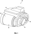
- FIG. 1 shows a perspective view of a drive arrangement 10.
- the drive arrangement 10 comprises an electric machine 12 for generating a torque and a transmission 14 coupled to the electric machine 12 for transmitting and/or translating the torque generated by the electric machine 12.
- the electric machine 12 and the transmission 14 are arranged in a housing 16.
- the drive arrangement 10 has power electronics 13 (or a control module) for controlling and/or regulating the drive arrangement 10.
- the drive arrangement 10 also has a parking lock 15 for blocking the torque transmission.
- FIG 2 shows a detail of a sectional view of the drive arrangement 10 according to Figure 1 .
- a section is also shown enlarged.
- the housing 16 has an intermediate wall 18 which is arranged between the electrical machine 12 and the transmission 14.
- An insert 20 is completely cast into the intermediate wall 18.
- the insert 20 is therefore arranged completely within the intermediate wall 18.
- the insert 20 has a cavity structure 22 for producing at least one cooling channel 24.
- Figure 3 shows a perspective sectional view of a first exemplary embodiment of the insert part 20.
- the insert part 20 shown corresponds to the insert part 20 Figure 2 .
- the insert part has a flat, circular base body 26.
- a section along the diameter of the circular insert part 22 is shown.
- the cavity structure 22 is designed in the form of three circular arc-shaped channels (later cooling channels 24).
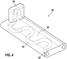
- Figure 4 shows a perspective view of a second exemplary embodiment of the insert part 20.
- the insert part 20 according to the second exemplary embodiment has a flat, essentially rectangular base body 26. Some corners and/or edges of the base body 26 are rounded.
- the insert part 20 has an arm 28, which in this case scans vertically from the base body 26.
- the cavity structure 22 has a channel (later cooling channel 24) which has a serpentine (winding), in particular meandering, shape in sections and is straight (rectilinear) in sections.
- the cavity structure 22 also extends through the boom 28.
- Figure 5 shows a perspective view of a third exemplary embodiment of the insert 20.
- the third exemplary embodiment of the insert 20 differs from that in Figure 4 shown second embodiment in that the insert 20 according to the third embodiment has three openings 30.
- the three openings 30 are arranged in the base body 26 of the insert 20 and extend through the entire thickness of the base body 26.
- the three openings 30 are arranged outside the cavity structure 22 (or its later cooling channel 24).
- the cavity structure 22 (or its later cooling channel 24) meanders around the openings 30. This can further increase the cooling effect.
Landscapes
- Engineering & Computer Science (AREA)
- Chemical & Material Sciences (AREA)
- Combustion & Propulsion (AREA)
- Transportation (AREA)
- Mechanical Engineering (AREA)
- Power Engineering (AREA)
- General Details Of Gearings (AREA)
Abstract
Description
- Die Erfindung betrifft eine Antriebsanordnung für ein Fahrzeug mit Merkmalen des Anspruchs 1, ein Verfahren zur Erzeugung einer Antriebsanordnung mit Merkmalen des Anspruchs 8, sowie ein Fahrzeug mit einer Antriebsanordnung mit Merkmalen des Anspruchs 10.
- Ein elektrischer Achsantrieb (E-Achse) besteht im Wesentlichen aus einer Leistungselektronik, einer elektrischen Maschine und einem Getriebe. Ein derartiger Antrieb ist bspw. in
DE 20 2017 003 396 U1 gezeigt. - Die im Getriebe erzeugte Wärme kann bspw. mit einem externen Wärmetauscher abgeführt werden. Dies kann bspw. bei einer komplett ölgekühlten Maschine notwendig sein.
- Nachteilig dabei ist, dass ein zusätzlicher Wärmetauscher hohe Kosten erzeugen kann, da dieser in der Regel eine mechanische oder elektrische Pumpe erfordert. Zudem muss der Wärmetauscher mit zusätzlichen Leitungen bzw. Kanälen angeschlossen werden. Ein (externer) Wärmetauscher benötigt zusätzlichen Bauraum, der nicht immer zur Verfügung gestellt werden kann.
- Erfindungsgemäß wird eine Antriebsanordnung für ein Fahrzeug, insbesondere für ein Elektrofahrzeug, vorgeschlagen, umfassend mindestens eine elektrische Maschine zur Erzeugung eines Drehmoments und mindestens ein mit der elektrischen Maschine gekoppeltes Getriebe zur Übertragung und/oder Übersetzung des von der elektrischen Maschine erzeugten Drehmoments. Das Getriebe ist insbesondere derart mit der elektrischen Maschine gekoppelt, dass das Getriebe mittels der elektrischen Maschine drehend angetrieben werden kann.
- Die Antriebsanordnung umfasst zudem ein Gehäuse, in dem die elektrische Maschine und das Getriebe angeordnet sind, wobei zwischen der elektrischen Maschine und dem Getriebe eine Zwischenwandung des Gehäuses angeordnet ist. Das Gehäuse kann als Gussteil, insbesondere als Aluminiumdruckgussteil, ausgebildet sein.
- Die Antriebsanordnung umfasst weiter mindestens ein in das Gehäuse eingegossenes Einlegeteil mit mindestens einer Hohlraumstruktur zur Erzeugung mindestens eines Kühlkanals. Die Hohlraumstruktur kann in sich abgeschlossen sein. Das Einlegeteil ist an oder in der Zwischenwandung des Gehäuses angeordnet.
- Das Einlegeteil kann derart an oder in der Zwischenwandung angeordnet sein, dass die Zwischenwandung das Einlegeteil zumindest teilweise oder vollständig einbettet. Die Zwischenwandung kann insbesondere als Lagerwand (Lager A-Seite (ALS)) ausgebildet sein. Die mittels des Einlegeteils erzeugte Hohlraumstruktur innerhalb der Zwischenwandung kann mindestens einen Kühlkanal darstellen und zur Kühlung der Zwischenwandung genutzt werden. So kann die Zwischenwandung zwischen der bspw. trocken (ohne Öl) laufenden elektrischen Maschine und dem bspw. mit Öl befüllten Getriebe gekühlt werden.
- Das Einlegeteil kann mittels additiver Fertigung (bspw. L-PBF-M (Powderbed fusion of metals with laser)) erzeugt werden. Das Einlegeteil kann aus einer metallischen Legierung gefertigt sein, welche eine gute Wärmeleistung aufweist. Dies kann bspw. eine Aluminiumbasislegierung sein. Denkbar ist auch eine Fertigung mit einer Eisenbasislegierung (Stahl). Insbesondere aufgrund der flexiblen Produktion der additiven Fertigung lassen sich Hohlraumstrukturen mit komplexen, unterschiedlichen Geometrien in einem äußerlich gleichen Einlegeteil realisieren. Dadurch kann eine hohe Formvarianz realisiert werden.
- Die Antriebsanordnung kann eine Leistungselektronik (bzw. ein Steuermodul/Steuergerät) zur Steuerung der elektrischen Maschine und/oder eine Parksperre zum Blockieren der Drehmomentübertragung aufweisen.
- Die Antriebsanordnung kann bspw. als E-Achse ausgebildet sein oder Bestandteil einer E-Achse bilden.
- Gemäß einer Weiterbildung kann das Einlegeteil einen flächigen, insbesondere in einer Ebene erstreckten, insbesondere ebenen, Grundkörper aufweisen. Der Grundkörper kann abgerundete Bereiche und/oder Kanten aufweisen. Der Grundkörper kann rund oder rechteckig ausgebildet sein. Die Hohlraumstruktur kann innerhalb des Grundkörpers verlaufen. Die Hohlraumstruktur innerhalb des Grundkörpers kann eine gewundene und/oder gerade verlaufende Form (Kontur) aufweisen.
- Gemäß einer Weiterbildung kann das Einlegeteil einen Ausleger aufweisen. Der Ausleger kann vom Grundkörper abragen (abstehen). Der Ausleger kann orthogonal zum Grundkörper orientiert sein. Die Hohlraumstruktur kann innerhalb des Auslegers verlaufen. Damit können auch schwer erreichbare Stellen und/oder Hotspots der zu kühlenden Komponente (bspw. Getriebe) erreicht und gekühlt werden.
- Gemäß einer Weiterbildung kann das Einlegeteil mindestens einen Durchbruch (bzw. Aussparung) aufweisen. Das Einlegeteil kann mehrere Durchbrüche bzw. Aussparungen aufweisen. Der Durchbruch oder die Durchbrüche können das Einlegeteil außerhalb der Hohlraumstruktur durchdringen. Der Durchbruch oder die Durchbrüche können vollständig im Grundkörper des Einlegeteils angeordnet sein (bzw. innerhalb des Grundkörpers verlaufen).
- Durch die Durchbrüche in dem Einlegeteil kann die Anbindung an das Gehäuse (Gussteil) erfolgen und Material bei der kostenintensiven additiven Herstellung des Einlegeteils eingespart werden. Zusätzlich kann so die Kühlleistung erhöht werden (größere Kontaktflächen zwischen dem Einlegeteil und dem Gehäuse bzw. dessen Zwischenwandung).
- Gemäß einer Weiterbildung kann das Einlegeteil aus zwei zusammengefügten, bspw. gelöteten und/oder geschweißten, Blechen hergestellt sein.
- Das Einlegeteil kann mittels Topologie-Optimierungs-Software bezüglich Masse und Belastungspfaden optimiert werden, um Fertigungskosten einzusparen.
- Gemäß einer Weiterbildung kann das Einlegeteil ein durch Innenhochdruck und/oder ein durch ein Hydroforming-Verfahren erzeugtes Bauteil sein.
- Minimale Wandstärken des Einlegeteils können abhängig von der Aufbau-Orientierung, Fertigungsparametern und der Technologie-, der Material-Auswahl und dem angelegten hydrodynamischen Druck eine Stärke von minimal 300 µm (ohne Obergrenze) aufweisen. Durch den materialsparenden Einsatz können Fertigungskosten eingespart werden.
- Gemäß einer Weiterbildung kann die Antriebsanordnung einen Kühlkreislauf zur Kühlung der elektrischen Maschine umfassen. Der durch das Einlegeteil erzeugte Kühlkanal kann mit dem Kühlkreislauf der elektrischen Maschine strömungsverbunden (bzw. fluidisch verbunden) sein. Damit kann mittels des Kühlkreislaufs der elektrischen Maschine die Zwischenwandung und damit das Getriebe gekühlt werden.
- Mit einer fluidischen Verbindung oder Strömungsverbindung ist vorliegend gemeint, dass ein Gas und/oder ein Fluid (Flüssigkeit) zwischen zwei fluidisch gekoppelten oder strömungsverbundenen Elementen bzw. zwischen zwei in fluidischer Verbindung oder Strömungsverbindung stehender Elemente fließen kann.
- Erfindungsgemäß wird ein Verfahren zur Erzeugung einer Antriebsanordnung, insbesondere einer Antriebsanordnung gemäß obiger Ausführungen, vorgeschlagen. Hinsichtlich der damit erzielbaren Vorteile wird auf die diesbezüglichen Ausführungen zur Antriebsanordnung verwiesen. Zur weiteren Ausgestaltung des Verfahrens können die im Zusammenhang mit der Antriebsanordnung beschriebenen und/oder die nachfolgend noch erläuterten Maßnahmen dienen.
- Das Verfahren umfasst die Schritte:
- Bereitstellen einer elektrischen Maschine zur Erzeugung eines Drehmoments.
- Bereitstellen eines mit der elektrischen Maschine gekoppelten Getriebes zur Übertragung und/oder Übersetzung des von der elektrischen Maschine erzeugten Drehmoments.
- Bereitstellen eines Gehäuses zur Aufnahme der elektrischen Maschine und des Getriebes.
- Bereitstellen eines Einlegeteils mit mindestens einer, insbesondere in sich abgeschlossenen, Hohlraumstruktur zur Erzeugung mindestens eines Kühlkanals.
- Füllen der Hohlraumstruktur mit einem Füllmedium, insbesondere mit metallischem Pulver.
- Eingießen des Einlegeteils in das Gehäuse, insbesondere in eine Zwischenwandung des Gehäuses. Das Einlegeteil wird insbesondere teilweise oder komplett umgossen.
- Anbohren und/oder Anfräsen der Hohlraumstruktur des Einlegeteils, so dass die, insbesondere in sich abgeschlossene, Hohlraumstruktur zugänglich ist.
- Entfernen des Füllmediums aus der Hohlraumstruktur des Einlegeteils.
- Das Füllmedium innerhalb der Hohlraumstruktur des Einlegeteils verhindert insbesondere, dass die Hohlraumstruktur im Druckgussprozess zerstört wird. Das Einlegeteil kann auch nach dem Druckgussprozess montiert werden. Das Gehäuse kann in einem Aluminiumdruckgussprozess hergestellt werden, wobei das Einlegeteil eingelegt und komplett umgossen werden kann.
- Zu geeignetem Zeitpunkt kann eine Montage der Antriebsanordnung erfolgen, insbesondere ein Anbau und/oder Einbau von Komponenten, bspw. der elektrischen Maschine, dem Getriebe und ggf. weiteren Komponenten, an oder in das Gehäuse der Antriebsanordnung. Dies kann bspw. nach Entfernen des Füllmediums aus der Hohlraumstruktur erfolgen.
- Gemäß einer Weiterbildung kann das Verfahren weiter den Schritt umfassen:
Strömungsverbinden (bzw. fluidisches Verbinden/Koppeln) der Hohlraumstruktur des Einlegeteils mit einem, insbesondere zur Kühlung der elektrischen Maschine vorgesehenen, Kühlkreislauf. Bei dem Kühlkreislauf der elektrischen Maschine kann es sich um einen Kühlkreislauf mit Flüssigkeit, bspw. einen Wasserkühlkreislauf, handeln. - Erfindungsgemäß wird ein Fahrzeug, insbesondere ein Elektrofahrzeug, mit einer Antriebsanordnung gemäß obiger Ausführungen vorgeschlagen. Hinsichtlich der damit erzielbaren Vorteile wird auf die diesbezüglichen Ausführungen zur Antriebsanordnung verwiesen. Zur weiteren Ausgestaltung des Fahrzeugs können die im Zusammenhang mit der Antriebsanordnung beschriebenen und/oder die nachfolgend noch erläuterten Maßnahmen dienen.
- Nachfolgend werden Ausführungsformen der Erfindung unter Bezugnahme auf die beiliegenden Zeichnungen erläutert. Es zeigen:
- Figur 1
- eine perspektivische Ansicht auf eine Antriebsanordnung;
- Figur 2
- einen Ausschnitt einer Schnittansicht der Antriebsanordnung gemäß
Figur 1 mit einem vergrößerten Ausschnitt; - Figur 3
- eine perspektivische Schnittdarstellung eines ersten Ausführungsbeispiels eines Einlegeteils;
- Figur 4
- eine perspektivische Darstellung eines zweiten Ausführungsbeispiels des Einlegeteils; und
- Figur 5
- eine perspektivische Darstellung eines dritten Ausführungsbeispiels des Einlegeteils.
-
Figur 1 zeigt eine perspektivische Ansicht auf eine Antriebsanordnung 10. Die Antriebsanordnung 10 umfasst eine elektrische Maschine 12 zur Erzeugung eines Drehmoments und ein mit der elektrischen Maschine 12 gekoppeltes Getriebe 14 zur Übertragung und/oder Übersetzung des von der elektrischen Maschine 12 erzeugten Drehmoments. Die elektrische Maschine 12 und das Getriebe 14 sind in einem Gehäuse 16 angeordnet. - Die Antriebsanordnung 10 weist vorliegend eine Leistungselektronik 13 (bzw. ein Steuermodul) zur Steuerung und/oder Regelung der Antriebsanordnung 10 auf. Die Antriebsanordnung 10 weist zudem vorliegend eine Parksperre 15 zum Blockieren der Drehmomentübertragung auf.
-
Figur 2 zeigt einen Ausschnitt einer Schnittansicht der Antriebsanordnung 10 gemäßFigur 1 . Der besseren Übersicht halber ist zudem ein Ausschnitt vergrößert dargestellt. - Das Gehäuse 16 weist eine Zwischenwandung 18 auf, die zwischen der elektrischen Maschine 12 und dem Getriebe 14 angeordnet ist. In die Zwischenwandung 18 ist ein Einlegeteil 20 vollständig eingegossen. Das Einlegeteil 20 ist also vollständig innerhalb der Zwischenwandung 18 angeordnet. Das Einlegeteil 20 weist eine Hohlraumstruktur 22 zur Erzeugung mindestens eines Kühlkanals 24 auf.
-
Figur 3 zeigt eine perspektivische Schnittdarstellung eines ersten Ausführungsbeispiels des Einlegeteils 20. Das dargestellte Einlegeteil 20 entspricht dem Einlegeteil 20 ausFigur 2 . Das Einlegeteil weist einen flächigen, kreisförmigen Grundkörper 26 auf. Es ist ein Schnitt entlang des Durchmessers des kreisförmig ausgebildeten Einlegeteils 22 dargestellt. Die Hohlraumstruktur 22 ist in Form von drei kreisbogenförmig verlaufenden Kanälen (spätere Kühlkanäle 24) ausgebildet. -
Figur 4 zeigt eine perspektivische Darstellung eines zweiten Ausführungsbeispiels des Einlegeteils 20. Das Einlegeteil 20 gemäß dem zweiten Ausführungsbeispiel weist einen flächigen, im Wesentlichen rechteckförmigen Grundkörper 26 auf. Einige Ecken und/oder Kanten des Grundkörpers 26 sind abgerundet ausgebildet. Das Einlegeteil 20 weist einen Ausleger 28 auf, der vorliegend senkrecht vom Grundkörper 26 abfragt. - Die Hohlraumstruktur 22 weist einen Kanal (späterer Kühlkanal 24) auf, der abschnittsweise eine geschlängelte (gewundene), insbesondere mäanderartig verlaufende, Form aufweist und abschnittsweise gerade (geradlinig) ausgebildet ist. Die Hohlraumstruktur 22 erstreckt sich ebenfalls durch den Ausleger 28.
-
Figur 5 zeigt eine perspektivische Darstellung eines dritten Ausführungsbeispiels des Einlegeteils 20. Das dritte Ausführungsbeispiel des Einlegers 20 unterscheidet sich von dem inFigur 4 gezeigten zweiten Ausführungsbeispiel dadurch, dass das Einlegeteil 20 gemäß dem dritten Ausführungsbeispiel drei Durchbrüche 30 aufweist. - Die drei Durchbrüche 30 sind im Grundkörper 26 des Einlegeteils 20 angeordnet und erstrecken sich durch die gesamte Dicke des Grundkörpers 26. Die drei Durchbrüche 30 sind außerhalb der Hohlraumstruktur 22 (bzw. deren späteren Kühlkanals 24) angeordnet. Die Hohlraumstruktur 22 (bzw. deren späterer Kühlkanal 24) schlängelt sich vorliegend um die Durchbrüche 30 herum. Hierdurch kann die Kühlwirkung nochmals erhöht werden.
Claims (10)
- Antriebsanordnung (10) für ein Fahrzeug, insbesondere für ein Elektrofahrzeug, umfassend:- mindestens eine elektrische Maschine (12) zur Erzeugung eines Drehmoments,- mindestens ein mit der elektrischen Maschine (12) gekoppeltes Getriebe (14) zur Übertragung und/oder Übersetzung des von der elektrischen Maschine (12) erzeugten Drehmoments,- ein Gehäuse (16), in dem die elektrische Maschine (12) und das Getriebe (14) angeordnet sind, wobei zwischen der elektrischen Maschine (12) und dem Getriebe (14) eine Zwischenwandung (18) des Gehäuses (16) angeordnet ist, und- mindestens ein in das Gehäuse (16) eingegossenes Einlegeteil (20) mit mindestens einer, insbesondere in sich abgeschlossenen, Hohlraumstruktur (22) zur Erzeugung mindestens eines Kühlkanals (24), wobei das Einlegeteil (20) an oder in der Zwischenwandung (18) des Gehäuses (16) angeordnet ist.
- Antriebsanordnung (10) nach Anspruch 1, dadurch gekennzeichnet, dass das Einlegeteil (20) einen flächigen Grundkörper (26) aufweist.
- Antriebsanordnung (10) nach Anspruch 2, dadurch gekennzeichnet, dass das Einlegeteil (20) einen Ausleger (28) aufweist, wobei der Ausleger (28) vom Grundkörper (26) abragt, insbesondere orthogonal zum Grundkörper (26) orientiert ist.
- Antriebsanordnung (10) nach einem der voranstehenden Ansprüche,
dadurch gekennzeichnet, dass das Einlegeteil (20) mindestens einen Durchbruch (30), insbesondere mehrere Durchbrüche (30), aufweist, wobei der Durchbruch (30), das Einlegeteil (20) außerhalb der Hohlraumstruktur (22) durchdringt, wobei der Durchbruch (30) insbesondere vollständig im Grundkörper (26) des Einlegeteils (20) angeordnet ist. - Antriebsanordnung (10) nach einem der voranstehenden Ansprüche,
dadurch gekennzeichnet, dass das Einlegeteil (20) aus zwei zusammengefügten Blechen hergestellt ist. - Antriebsanordnung (10) nach einem der Ansprüche 1 bis 4, dadurch gekennzeichnet, dass das Einlegeteil (20) ein durch Innenhochdruck und/oder Hydroforming erzeugtes Bauteil ist.
- Antriebsanordnung (10) nach einem der voranstehenden Ansprüche,
dadurch gekennzeichnet, dass die Antriebsanordnung (10) einen Kühlkreislauf zur Kühlung der elektrischen Maschine (12) umfasst, wobei der durch das Einlegeteil (20) erzeugte Kühlkanal (24) mit dem Kühlkreislauf der elektrischen Maschine (12) strömungsverbunden ist. - Verfahren zur Erzeugung einer Antriebsanordnung (10), insbesondere einer Antriebsanordnung (10) nach einem der voranstehenden Ansprüche, umfassend die Schritte:- Bereitstellen einer elektrischen Maschine (12) zur Erzeugung eines Drehmoments;- Bereitstellen eines mit der elektrischen Maschine (12) gekoppelten Getriebes (14) zur Übertragung und/oder Übersetzung des von der elektrischen Maschine (12) erzeugten Drehmoments;- Bereitstellen eines Gehäuses (16) zur Aufnahme der elektrischen Maschine (12) und des Getriebes (14);- Bereitstellen eines Einlegeteils (20) mit mindestens einer, insbesondere in sich abgeschlossenen, Hohlraumstruktur (22) zur Erzeugung mindestens eines Kühlkanals (24);- Füllen der Hohlraumstruktur (22) mit einem Füllmedium, insbesondere mit metallischem Pulver;- Eingießen des Einlegeteils (20) in das Gehäuse (16), insbesondere in eine Zwischenwandung (18) des Gehäuses (16);- Anbohren und/oder Anfräsen der Hohlraumstruktur (22) des Einlegeteils (20); und- Entfernen des Füllmediums aus der Hohlraumstruktur (22) des Einlegeteils (20).
- Verfahren nach Anspruch 8, dadurch gekennzeichnet, dass das Verfahren weiter den Schritt umfasst:- Strömungsverbinden der Hohlraumstruktur (22) des Einlegeteils (20) mit einem, insbesondere zur Kühlung der elektrischen Maschine (12) vorgesehenen, Kühlkreislauf.
- Fahrzeug, insbesondere Elektrofahrzeug, mit mindestens einer Antriebsanordnung nach einem der Ansprüche 1 bis 7.
Applications Claiming Priority (1)
| Application Number | Priority Date | Filing Date | Title |
|---|---|---|---|
| DE102022206440.2A DE102022206440A1 (de) | 2022-06-27 | 2022-06-27 | Antriebsanordnung, Verfahren zur Erzeugung einer Antriebsanordnung und ein Fahrzeug mit einer Antriebsanordnung |
Publications (2)
| Publication Number | Publication Date |
|---|---|
| EP4299350A1 true EP4299350A1 (de) | 2024-01-03 |
| EP4299350B1 EP4299350B1 (de) | 2025-02-12 |
Family
ID=86497879
Family Applications (1)
| Application Number | Title | Priority Date | Filing Date |
|---|---|---|---|
| EP23174526.6A Active EP4299350B1 (de) | 2022-06-27 | 2023-05-22 | Antriebsanordnung, verfahren zur erzeugung einer antriebsanordnung und ein fahrzeug mit einer antriebsanordnung |
Country Status (2)
| Country | Link |
|---|---|
| EP (1) | EP4299350B1 (de) |
| DE (1) | DE102022206440A1 (de) |
Families Citing this family (1)
| Publication number | Priority date | Publication date | Assignee | Title |
|---|---|---|---|---|
| DE102024205764A1 (de) | 2024-06-21 | 2025-12-24 | Robert Bosch Gesellschaft mit beschränkter Haftung | Gehäuse für einen elektrischen Antrieb und elektrischer Antrieb für ein Fahrzeug |
Citations (5)
| Publication number | Priority date | Publication date | Assignee | Title |
|---|---|---|---|---|
| US20160164378A1 (en) * | 2014-12-04 | 2016-06-09 | Atieva, Inc. | Motor Cooling System |
| DE202017003396U1 (de) | 2017-06-28 | 2017-07-26 | Gkn Automotive Ltd. | Antriebseinheit für ein Kraftfahrzeug |
| US20210394600A1 (en) * | 2018-10-04 | 2021-12-23 | Gkn Automotive Limited | Electric drive with cooling |
| EP3937353A1 (de) * | 2019-03-20 | 2022-01-12 | Aiways Automobile (Shanghai) Co., Ltd | Integrierte elektrische antriebseinheit und elektrisches fahrzeug |
| DE102020211432A1 (de) * | 2020-09-11 | 2022-03-17 | Robert Bosch Gesellschaft mit beschränkter Haftung | Elektrische Antriebseinheit und ein Fahrzeug mit einer entsprechenden elektrischen Antriebseinheit |
-
2022
- 2022-06-27 DE DE102022206440.2A patent/DE102022206440A1/de active Pending
-
2023
- 2023-05-22 EP EP23174526.6A patent/EP4299350B1/de active Active
Patent Citations (5)
| Publication number | Priority date | Publication date | Assignee | Title |
|---|---|---|---|---|
| US20160164378A1 (en) * | 2014-12-04 | 2016-06-09 | Atieva, Inc. | Motor Cooling System |
| DE202017003396U1 (de) | 2017-06-28 | 2017-07-26 | Gkn Automotive Ltd. | Antriebseinheit für ein Kraftfahrzeug |
| US20210394600A1 (en) * | 2018-10-04 | 2021-12-23 | Gkn Automotive Limited | Electric drive with cooling |
| EP3937353A1 (de) * | 2019-03-20 | 2022-01-12 | Aiways Automobile (Shanghai) Co., Ltd | Integrierte elektrische antriebseinheit und elektrisches fahrzeug |
| DE102020211432A1 (de) * | 2020-09-11 | 2022-03-17 | Robert Bosch Gesellschaft mit beschränkter Haftung | Elektrische Antriebseinheit und ein Fahrzeug mit einer entsprechenden elektrischen Antriebseinheit |
Also Published As
| Publication number | Publication date |
|---|---|
| EP4299350B1 (de) | 2025-02-12 |
| DE102022206440A1 (de) | 2023-12-28 |
Similar Documents
| Publication | Publication Date | Title |
|---|---|---|
| DE102015205543A1 (de) | Hydraulikblock für ein Hydroaggregat einer Bremsregelung einer hydraulischen Fahrzeugbremsanlage | |
| EP1930681A1 (de) | Wärmetauscher, Anordnung und Verfahren zur Herstellung eines Wärmetauschers | |
| EP4299350B1 (de) | Antriebsanordnung, verfahren zur erzeugung einer antriebsanordnung und ein fahrzeug mit einer antriebsanordnung | |
| DE19800097A1 (de) | Span- oder Schneidwerkzeug und Verfahren zu dessen Herstellung | |
| DE102017216676A1 (de) | Verfahren zur Herstellung eines dreidimensionalen Produktes | |
| WO2020169189A1 (de) | Mehrteiliges segmentiertes e-maschinengehäuse | |
| EP4210980B1 (de) | Elektrische antriebseinheit und ein fahrzeug mit einer entsprechenden elektrischen antriebseinheit | |
| DE102017202667B4 (de) | Wärmetauscher | |
| DE102021211340A1 (de) | Rotor für einen Elektromotor | |
| DE112013001561T5 (de) | Gelötete Anschlussanordnung | |
| DE102009013408A1 (de) | Drehmomentwandlerschaufel | |
| DE112006000762T5 (de) | Ölwegstruktur | |
| EP3815477B1 (de) | Herstellungsverfahren eines gehäuses für eine elektronik | |
| DE102006005185A1 (de) | Baueinheit mit einem Steuergerätgehäuse und einem Hydroaggregatgehäuse | |
| EP3546812A1 (de) | Hydraulikkomponentensystem mit einer zumindest teilweise generativ hergestellten hydraulikkomponente | |
| DE102011086564A1 (de) | Führungszapfen für ein Anfahrelement | |
| DE102010042400A1 (de) | Verfahren zum Herstellen einer hydraulischen Vorrichtung | |
| DE19920427B4 (de) | Vorrichtung zum Verbinden von Rohren in unterschiedlichen Winkelstellungen | |
| AT528192B1 (de) | Käfigläufer und Verfahren zum Herstellen eines Käfigläufers | |
| WO2021213805A1 (de) | Verfahren zur befestigung eines permanentmagneten | |
| EP3992510B1 (de) | Fluidverbindungsanordnung | |
| DE102019216579A1 (de) | Hybrides Leichtbaugehäuse für einen wassergekühlten Elektromotor | |
| DE102022117118A1 (de) | Herstellungsverfahren für Hohlventile und Hohlventil | |
| DE102023209389A1 (de) | Kühlkörper mit einem Leistungsmodul, Verfahren zur Herstellung, Antriebsinverter und Kraftfahrzeug | |
| DE102022213956A1 (de) | Lösbare verbindung für eine, insbesondere elektrische, maschine, elektrische maschine und verfahren zum herstellen einer lösbaren verbindung bei der, insbesondere elektrischen, maschine |
Legal Events
| Date | Code | Title | Description |
|---|---|---|---|
| PUAI | Public reference made under article 153(3) epc to a published international application that has entered the european phase |
Free format text: ORIGINAL CODE: 0009012 |
|
| STAA | Information on the status of an ep patent application or granted ep patent |
Free format text: STATUS: THE APPLICATION HAS BEEN PUBLISHED |
|
| AK | Designated contracting states |
Kind code of ref document: A1 Designated state(s): AL AT BE BG CH CY CZ DE DK EE ES FI FR GB GR HR HU IE IS IT LI LT LU LV MC ME MK MT NL NO PL PT RO RS SE SI SK SM TR |
|
| STAA | Information on the status of an ep patent application or granted ep patent |
Free format text: STATUS: REQUEST FOR EXAMINATION WAS MADE |
|
| 17P | Request for examination filed |
Effective date: 20240703 |
|
| RBV | Designated contracting states (corrected) |
Designated state(s): AL AT BE BG CH CY CZ DE DK EE ES FI FR GB GR HR HU IE IS IT LI LT LU LV MC ME MK MT NL NO PL PT RO RS SE SI SK SM TR |
|
| GRAP | Despatch of communication of intention to grant a patent |
Free format text: ORIGINAL CODE: EPIDOSNIGR1 |
|
| STAA | Information on the status of an ep patent application or granted ep patent |
Free format text: STATUS: GRANT OF PATENT IS INTENDED |
|
| INTG | Intention to grant announced |
Effective date: 20241106 |
|
| GRAS | Grant fee paid |
Free format text: ORIGINAL CODE: EPIDOSNIGR3 |
|
| GRAA | (expected) grant |
Free format text: ORIGINAL CODE: 0009210 |
|
| STAA | Information on the status of an ep patent application or granted ep patent |
Free format text: STATUS: THE PATENT HAS BEEN GRANTED |
|
| AK | Designated contracting states |
Kind code of ref document: B1 Designated state(s): AL AT BE BG CH CY CZ DE DK EE ES FI FR GB GR HR HU IE IS IT LI LT LU LV MC ME MK MT NL NO PL PT RO RS SE SI SK SM TR |
|
| REG | Reference to a national code |
Ref country code: GB Ref legal event code: FG4D Free format text: NOT ENGLISH |
|
| REG | Reference to a national code |
Ref country code: CH Ref legal event code: EP |
|
| REG | Reference to a national code |
Ref country code: DE Ref legal event code: R096 Ref document number: 502023000554 Country of ref document: DE |
|
| REG | Reference to a national code |
Ref country code: IE Ref legal event code: FG4D Free format text: LANGUAGE OF EP DOCUMENT: GERMAN |
|
| REG | Reference to a national code |
Ref country code: NL Ref legal event code: MP Effective date: 20250212 |
|
| PG25 | Lapsed in a contracting state [announced via postgrant information from national office to epo] |
Ref country code: RS Free format text: LAPSE BECAUSE OF FAILURE TO SUBMIT A TRANSLATION OF THE DESCRIPTION OR TO PAY THE FEE WITHIN THE PRESCRIBED TIME-LIMIT Effective date: 20250512 |
|
| PG25 | Lapsed in a contracting state [announced via postgrant information from national office to epo] |
Ref country code: FI Free format text: LAPSE BECAUSE OF FAILURE TO SUBMIT A TRANSLATION OF THE DESCRIPTION OR TO PAY THE FEE WITHIN THE PRESCRIBED TIME-LIMIT Effective date: 20250212 |
|
| PG25 | Lapsed in a contracting state [announced via postgrant information from national office to epo] |
Ref country code: PL Free format text: LAPSE BECAUSE OF FAILURE TO SUBMIT A TRANSLATION OF THE DESCRIPTION OR TO PAY THE FEE WITHIN THE PRESCRIBED TIME-LIMIT Effective date: 20250212 |
|
| PG25 | Lapsed in a contracting state [announced via postgrant information from national office to epo] |
Ref country code: ES Free format text: LAPSE BECAUSE OF FAILURE TO SUBMIT A TRANSLATION OF THE DESCRIPTION OR TO PAY THE FEE WITHIN THE PRESCRIBED TIME-LIMIT Effective date: 20250212 |
|
| REG | Reference to a national code |
Ref country code: LT Ref legal event code: MG9D |
|
| PG25 | Lapsed in a contracting state [announced via postgrant information from national office to epo] |
Ref country code: IS Free format text: LAPSE BECAUSE OF FAILURE TO SUBMIT A TRANSLATION OF THE DESCRIPTION OR TO PAY THE FEE WITHIN THE PRESCRIBED TIME-LIMIT Effective date: 20250612 Ref country code: NO Free format text: LAPSE BECAUSE OF FAILURE TO SUBMIT A TRANSLATION OF THE DESCRIPTION OR TO PAY THE FEE WITHIN THE PRESCRIBED TIME-LIMIT Effective date: 20250512 |
|
| PG25 | Lapsed in a contracting state [announced via postgrant information from national office to epo] |
Ref country code: NL Free format text: LAPSE BECAUSE OF FAILURE TO SUBMIT A TRANSLATION OF THE DESCRIPTION OR TO PAY THE FEE WITHIN THE PRESCRIBED TIME-LIMIT Effective date: 20250212 |
|
| PGFP | Annual fee paid to national office [announced via postgrant information from national office to epo] |
Ref country code: IT Payment date: 20250531 Year of fee payment: 3 |
|
| PG25 | Lapsed in a contracting state [announced via postgrant information from national office to epo] |
Ref country code: HR Free format text: LAPSE BECAUSE OF FAILURE TO SUBMIT A TRANSLATION OF THE DESCRIPTION OR TO PAY THE FEE WITHIN THE PRESCRIBED TIME-LIMIT Effective date: 20250212 |
|
| PG25 | Lapsed in a contracting state [announced via postgrant information from national office to epo] |
Ref country code: PT Free format text: LAPSE BECAUSE OF FAILURE TO SUBMIT A TRANSLATION OF THE DESCRIPTION OR TO PAY THE FEE WITHIN THE PRESCRIBED TIME-LIMIT Effective date: 20250612 Ref country code: LV Free format text: LAPSE BECAUSE OF FAILURE TO SUBMIT A TRANSLATION OF THE DESCRIPTION OR TO PAY THE FEE WITHIN THE PRESCRIBED TIME-LIMIT Effective date: 20250212 |
|
| PGFP | Annual fee paid to national office [announced via postgrant information from national office to epo] |
Ref country code: FR Payment date: 20250521 Year of fee payment: 3 |
|
| PG25 | Lapsed in a contracting state [announced via postgrant information from national office to epo] |
Ref country code: GR Free format text: LAPSE BECAUSE OF FAILURE TO SUBMIT A TRANSLATION OF THE DESCRIPTION OR TO PAY THE FEE WITHIN THE PRESCRIBED TIME-LIMIT Effective date: 20250513 Ref country code: BG Free format text: LAPSE BECAUSE OF FAILURE TO SUBMIT A TRANSLATION OF THE DESCRIPTION OR TO PAY THE FEE WITHIN THE PRESCRIBED TIME-LIMIT Effective date: 20250212 |
|
| PGFP | Annual fee paid to national office [announced via postgrant information from national office to epo] |
Ref country code: AT Payment date: 20250721 Year of fee payment: 3 |
|
| PG25 | Lapsed in a contracting state [announced via postgrant information from national office to epo] |
Ref country code: SE Free format text: LAPSE BECAUSE OF FAILURE TO SUBMIT A TRANSLATION OF THE DESCRIPTION OR TO PAY THE FEE WITHIN THE PRESCRIBED TIME-LIMIT Effective date: 20250212 |
|
| PG25 | Lapsed in a contracting state [announced via postgrant information from national office to epo] |
Ref country code: SM Free format text: LAPSE BECAUSE OF FAILURE TO SUBMIT A TRANSLATION OF THE DESCRIPTION OR TO PAY THE FEE WITHIN THE PRESCRIBED TIME-LIMIT Effective date: 20250212 |
|
| PG25 | Lapsed in a contracting state [announced via postgrant information from national office to epo] |
Ref country code: DK Free format text: LAPSE BECAUSE OF FAILURE TO SUBMIT A TRANSLATION OF THE DESCRIPTION OR TO PAY THE FEE WITHIN THE PRESCRIBED TIME-LIMIT Effective date: 20250212 |
|
| PGFP | Annual fee paid to national office [announced via postgrant information from national office to epo] |
Ref country code: DE Payment date: 20250716 Year of fee payment: 3 |
|
| PG25 | Lapsed in a contracting state [announced via postgrant information from national office to epo] |
Ref country code: EE Free format text: LAPSE BECAUSE OF FAILURE TO SUBMIT A TRANSLATION OF THE DESCRIPTION OR TO PAY THE FEE WITHIN THE PRESCRIBED TIME-LIMIT Effective date: 20250212 Ref country code: CZ Free format text: LAPSE BECAUSE OF FAILURE TO SUBMIT A TRANSLATION OF THE DESCRIPTION OR TO PAY THE FEE WITHIN THE PRESCRIBED TIME-LIMIT Effective date: 20250212 |
|
| PG25 | Lapsed in a contracting state [announced via postgrant information from national office to epo] |
Ref country code: RO Free format text: LAPSE BECAUSE OF FAILURE TO SUBMIT A TRANSLATION OF THE DESCRIPTION OR TO PAY THE FEE WITHIN THE PRESCRIBED TIME-LIMIT Effective date: 20250212 |
|
| PG25 | Lapsed in a contracting state [announced via postgrant information from national office to epo] |
Ref country code: SK Free format text: LAPSE BECAUSE OF FAILURE TO SUBMIT A TRANSLATION OF THE DESCRIPTION OR TO PAY THE FEE WITHIN THE PRESCRIBED TIME-LIMIT Effective date: 20250212 |
|
| REG | Reference to a national code |
Ref country code: DE Ref legal event code: R097 Ref document number: 502023000554 Country of ref document: DE |
|
| PLBE | No opposition filed within time limit |
Free format text: ORIGINAL CODE: 0009261 |
|
| STAA | Information on the status of an ep patent application or granted ep patent |
Free format text: STATUS: NO OPPOSITION FILED WITHIN TIME LIMIT |
|
| PG25 | Lapsed in a contracting state [announced via postgrant information from national office to epo] |
Ref country code: LU Free format text: LAPSE BECAUSE OF NON-PAYMENT OF DUE FEES Effective date: 20250522 |
|
| 26N | No opposition filed |
Effective date: 20251113 |
|
| REG | Reference to a national code |
Ref country code: BE Ref legal event code: MM Effective date: 20250531 |
|
| PG25 | Lapsed in a contracting state [announced via postgrant information from national office to epo] |
Ref country code: MC Free format text: LAPSE BECAUSE OF FAILURE TO SUBMIT A TRANSLATION OF THE DESCRIPTION OR TO PAY THE FEE WITHIN THE PRESCRIBED TIME-LIMIT Effective date: 20250212 |
|
| PG25 | Lapsed in a contracting state [announced via postgrant information from national office to epo] |
Ref country code: IE Free format text: LAPSE BECAUSE OF NON-PAYMENT OF DUE FEES Effective date: 20250522 |
|
| PG25 | Lapsed in a contracting state [announced via postgrant information from national office to epo] |
Ref country code: BE Free format text: LAPSE BECAUSE OF NON-PAYMENT OF DUE FEES Effective date: 20250531 |