EP4299029A2 - Cone beam computed tomography integration for creating a navigation pathway to a target in the lung and method of navigating to the target - Google Patents
Cone beam computed tomography integration for creating a navigation pathway to a target in the lung and method of navigating to the target Download PDFInfo
- Publication number
- EP4299029A2 EP4299029A2 EP23182430.1A EP23182430A EP4299029A2 EP 4299029 A2 EP4299029 A2 EP 4299029A2 EP 23182430 A EP23182430 A EP 23182430A EP 4299029 A2 EP4299029 A2 EP 4299029A2
- Authority
- EP
- European Patent Office
- Prior art keywords
- patient
- computed tomography
- cone beam
- beam computed
- interest
- Prior art date
- Legal status (The legal status is an assumption and is not a legal conclusion. Google has not performed a legal analysis and makes no representation as to the accuracy of the status listed.)
- Granted
Links
Images



Classifications
-
- A—HUMAN NECESSITIES
- A61—MEDICAL OR VETERINARY SCIENCE; HYGIENE
- A61B—DIAGNOSIS; SURGERY; IDENTIFICATION
- A61B34/00—Computer-aided surgery; Manipulators or robots specially adapted for use in surgery
- A61B34/10—Computer-aided planning, simulation or modelling of surgical operations
-
- A—HUMAN NECESSITIES
- A61—MEDICAL OR VETERINARY SCIENCE; HYGIENE
- A61B—DIAGNOSIS; SURGERY; IDENTIFICATION
- A61B6/00—Apparatus or devices for radiation diagnosis; Apparatus or devices for radiation diagnosis combined with radiation therapy equipment
- A61B6/02—Arrangements for diagnosis sequentially in different planes; Stereoscopic radiation diagnosis
- A61B6/03—Computed tomography [CT]
-
- A—HUMAN NECESSITIES
- A61—MEDICAL OR VETERINARY SCIENCE; HYGIENE
- A61B—DIAGNOSIS; SURGERY; IDENTIFICATION
- A61B34/00—Computer-aided surgery; Manipulators or robots specially adapted for use in surgery
- A61B34/20—Surgical navigation systems; Devices for tracking or guiding surgical instruments, e.g. for frameless stereotaxis
-
- A—HUMAN NECESSITIES
- A61—MEDICAL OR VETERINARY SCIENCE; HYGIENE
- A61B—DIAGNOSIS; SURGERY; IDENTIFICATION
- A61B6/00—Apparatus or devices for radiation diagnosis; Apparatus or devices for radiation diagnosis combined with radiation therapy equipment
- A61B6/02—Arrangements for diagnosis sequentially in different planes; Stereoscopic radiation diagnosis
- A61B6/03—Computed tomography [CT]
- A61B6/032—Transmission computed tomography [CT]
-
- A—HUMAN NECESSITIES
- A61—MEDICAL OR VETERINARY SCIENCE; HYGIENE
- A61B—DIAGNOSIS; SURGERY; IDENTIFICATION
- A61B6/00—Apparatus or devices for radiation diagnosis; Apparatus or devices for radiation diagnosis combined with radiation therapy equipment
- A61B6/12—Arrangements for detecting or locating foreign bodies
-
- A—HUMAN NECESSITIES
- A61—MEDICAL OR VETERINARY SCIENCE; HYGIENE
- A61B—DIAGNOSIS; SURGERY; IDENTIFICATION
- A61B6/00—Apparatus or devices for radiation diagnosis; Apparatus or devices for radiation diagnosis combined with radiation therapy equipment
- A61B6/40—Arrangements for generating radiation specially adapted for radiation diagnosis
- A61B6/4064—Arrangements for generating radiation specially adapted for radiation diagnosis specially adapted for producing a particular type of beam
- A61B6/4085—Cone-beams
-
- A—HUMAN NECESSITIES
- A61—MEDICAL OR VETERINARY SCIENCE; HYGIENE
- A61B—DIAGNOSIS; SURGERY; IDENTIFICATION
- A61B6/00—Apparatus or devices for radiation diagnosis; Apparatus or devices for radiation diagnosis combined with radiation therapy equipment
- A61B6/44—Constructional features of apparatus for radiation diagnosis
- A61B6/4405—Constructional features of apparatus for radiation diagnosis the apparatus being movable or portable, e.g. handheld or mounted on a trolley
-
- A—HUMAN NECESSITIES
- A61—MEDICAL OR VETERINARY SCIENCE; HYGIENE
- A61B—DIAGNOSIS; SURGERY; IDENTIFICATION
- A61B6/00—Apparatus or devices for radiation diagnosis; Apparatus or devices for radiation diagnosis combined with radiation therapy equipment
- A61B6/52—Devices using data or image processing specially adapted for radiation diagnosis
- A61B6/5211—Devices using data or image processing specially adapted for radiation diagnosis involving processing of medical diagnostic data
- A61B6/5223—Devices using data or image processing specially adapted for radiation diagnosis involving processing of medical diagnostic data generating planar views from image data, e.g. extracting a coronal view from a 3D image
-
- A—HUMAN NECESSITIES
- A61—MEDICAL OR VETERINARY SCIENCE; HYGIENE
- A61B—DIAGNOSIS; SURGERY; IDENTIFICATION
- A61B90/00—Instruments, implements or accessories specially adapted for surgery or diagnosis and not covered by any of the groups A61B1/00 - A61B50/00, e.g. for luxation treatment or for protecting wound edges
- A61B90/10—Instruments, implements or accessories specially adapted for surgery or diagnosis and not covered by any of the groups A61B1/00 - A61B50/00, e.g. for luxation treatment or for protecting wound edges for stereotaxic surgery, e.g. frame-based stereotaxis
- A61B90/11—Instruments, implements or accessories specially adapted for surgery or diagnosis and not covered by any of the groups A61B1/00 - A61B50/00, e.g. for luxation treatment or for protecting wound edges for stereotaxic surgery, e.g. frame-based stereotaxis with guides for needles or instruments, e.g. arcuate slides or ball joints
-
- A—HUMAN NECESSITIES
- A61—MEDICAL OR VETERINARY SCIENCE; HYGIENE
- A61B—DIAGNOSIS; SURGERY; IDENTIFICATION
- A61B90/00—Instruments, implements or accessories specially adapted for surgery or diagnosis and not covered by any of the groups A61B1/00 - A61B50/00, e.g. for luxation treatment or for protecting wound edges
- A61B90/36—Image-producing devices or illumination devices not otherwise provided for
- A61B90/37—Surgical systems with images on a monitor during operation
-
- G—PHYSICS
- G06—COMPUTING OR CALCULATING; COUNTING
- G06T—IMAGE DATA PROCESSING OR GENERATION, IN GENERAL
- G06T7/00—Image analysis
- G06T7/30—Determination of transform parameters for the alignment of images, i.e. image registration
- G06T7/33—Determination of transform parameters for the alignment of images, i.e. image registration using feature-based methods
- G06T7/344—Determination of transform parameters for the alignment of images, i.e. image registration using feature-based methods involving models
-
- A—HUMAN NECESSITIES
- A61—MEDICAL OR VETERINARY SCIENCE; HYGIENE
- A61B—DIAGNOSIS; SURGERY; IDENTIFICATION
- A61B17/00—Surgical instruments, devices or methods
- A61B2017/00743—Type of operation; Specification of treatment sites
- A61B2017/00809—Lung operations
-
- A—HUMAN NECESSITIES
- A61—MEDICAL OR VETERINARY SCIENCE; HYGIENE
- A61B—DIAGNOSIS; SURGERY; IDENTIFICATION
- A61B34/00—Computer-aided surgery; Manipulators or robots specially adapted for use in surgery
- A61B34/10—Computer-aided planning, simulation or modelling of surgical operations
- A61B2034/101—Computer-aided simulation of surgical operations
- A61B2034/105—Modelling of the patient, e.g. for ligaments or bones
-
- A—HUMAN NECESSITIES
- A61—MEDICAL OR VETERINARY SCIENCE; HYGIENE
- A61B—DIAGNOSIS; SURGERY; IDENTIFICATION
- A61B34/00—Computer-aided surgery; Manipulators or robots specially adapted for use in surgery
- A61B34/10—Computer-aided planning, simulation or modelling of surgical operations
- A61B2034/107—Visualisation of planned trajectories or target regions
-
- A—HUMAN NECESSITIES
- A61—MEDICAL OR VETERINARY SCIENCE; HYGIENE
- A61B—DIAGNOSIS; SURGERY; IDENTIFICATION
- A61B34/00—Computer-aided surgery; Manipulators or robots specially adapted for use in surgery
- A61B34/20—Surgical navigation systems; Devices for tracking or guiding surgical instruments, e.g. for frameless stereotaxis
- A61B2034/2046—Tracking techniques
- A61B2034/2051—Electromagnetic tracking systems
-
- A—HUMAN NECESSITIES
- A61—MEDICAL OR VETERINARY SCIENCE; HYGIENE
- A61B—DIAGNOSIS; SURGERY; IDENTIFICATION
- A61B34/00—Computer-aided surgery; Manipulators or robots specially adapted for use in surgery
- A61B34/20—Surgical navigation systems; Devices for tracking or guiding surgical instruments, e.g. for frameless stereotaxis
- A61B2034/2046—Tracking techniques
- A61B2034/2061—Tracking techniques using shape-sensors, e.g. fiber shape sensors with Bragg gratings
-
- A—HUMAN NECESSITIES
- A61—MEDICAL OR VETERINARY SCIENCE; HYGIENE
- A61B—DIAGNOSIS; SURGERY; IDENTIFICATION
- A61B34/00—Computer-aided surgery; Manipulators or robots specially adapted for use in surgery
- A61B34/20—Surgical navigation systems; Devices for tracking or guiding surgical instruments, e.g. for frameless stereotaxis
- A61B2034/2046—Tracking techniques
- A61B2034/2065—Tracking using image or pattern recognition
-
- A—HUMAN NECESSITIES
- A61—MEDICAL OR VETERINARY SCIENCE; HYGIENE
- A61B—DIAGNOSIS; SURGERY; IDENTIFICATION
- A61B90/00—Instruments, implements or accessories specially adapted for surgery or diagnosis and not covered by any of the groups A61B1/00 - A61B50/00, e.g. for luxation treatment or for protecting wound edges
- A61B90/36—Image-producing devices or illumination devices not otherwise provided for
- A61B90/37—Surgical systems with images on a monitor during operation
- A61B2090/376—Surgical systems with images on a monitor during operation using X-rays, e.g. fluoroscopy
- A61B2090/3762—Surgical systems with images on a monitor during operation using X-rays, e.g. fluoroscopy using computed tomography systems [CT]
- A61B2090/3764—Surgical systems with images on a monitor during operation using X-rays, e.g. fluoroscopy using computed tomography systems [CT] with a rotating C-arm having a cone beam emitting source
-
- A—HUMAN NECESSITIES
- A61—MEDICAL OR VETERINARY SCIENCE; HYGIENE
- A61B—DIAGNOSIS; SURGERY; IDENTIFICATION
- A61B6/00—Apparatus or devices for radiation diagnosis; Apparatus or devices for radiation diagnosis combined with radiation therapy equipment
- A61B6/04—Positioning of patients; Tiltable beds or the like
- A61B6/0492—Positioning of patients; Tiltable beds or the like using markers or indicia for aiding patient positioning
-
- G—PHYSICS
- G06—COMPUTING OR CALCULATING; COUNTING
- G06T—IMAGE DATA PROCESSING OR GENERATION, IN GENERAL
- G06T2207/00—Indexing scheme for image analysis or image enhancement
- G06T2207/10—Image acquisition modality
- G06T2207/10016—Video; Image sequence
-
- G—PHYSICS
- G06—COMPUTING OR CALCULATING; COUNTING
- G06T—IMAGE DATA PROCESSING OR GENERATION, IN GENERAL
- G06T2207/00—Indexing scheme for image analysis or image enhancement
- G06T2207/10—Image acquisition modality
- G06T2207/10072—Tomographic images
- G06T2207/10081—Computed x-ray tomography [CT]
-
- G—PHYSICS
- G06—COMPUTING OR CALCULATING; COUNTING
- G06T—IMAGE DATA PROCESSING OR GENERATION, IN GENERAL
- G06T2207/00—Indexing scheme for image analysis or image enhancement
- G06T2207/10—Image acquisition modality
- G06T2207/10072—Tomographic images
- G06T2207/10088—Magnetic resonance imaging [MRI]
-
- G—PHYSICS
- G06—COMPUTING OR CALCULATING; COUNTING
- G06T—IMAGE DATA PROCESSING OR GENERATION, IN GENERAL
- G06T2207/00—Indexing scheme for image analysis or image enhancement
- G06T2207/10—Image acquisition modality
- G06T2207/10072—Tomographic images
- G06T2207/10104—Positron emission tomography [PET]
-
- G—PHYSICS
- G06—COMPUTING OR CALCULATING; COUNTING
- G06T—IMAGE DATA PROCESSING OR GENERATION, IN GENERAL
- G06T2207/00—Indexing scheme for image analysis or image enhancement
- G06T2207/20—Special algorithmic details
- G06T2207/20092—Interactive image processing based on input by user
- G06T2207/20104—Interactive definition of region of interest [ROI]
Definitions
- the present disclosure relates to the field of navigation of medical devices within a patient, and in particular, planning a pathway through a luminal network of a patient and navigating medical devices to a target.
- MRI magnetic resonance imaging
- CT computed tomography
- CBCT cone-beam computed tomography
- fluoroscopy including 3D fluoroscopy
- pre-operative scans may be utilized for target identification and intraoperative guidance.
- real-time imaging may be required to obtain a more accurate and current image of the target area.
- real-time image data displaying the current location of a medical device with respect to the target and its surroundings may be needed to navigate the medical device to the target in a safe and accurate manner (e.g., without causing damage to other organs or tissue).
- an endoscopic approach has proven useful in navigating to areas of interest within a patient.
- endoscopic navigation systems have been developed that use previously acquired MRI data or CT image data to generate a three-dimensional (3D) rendering, model, or volume of the particular body part such as the lungs.
- the acquired MRI data or CT Image data may be acquired during the procedure (perioperatively).
- the resulting volume generated from the MRI scan or CT scan is then utilized to create a navigation plan to facilitate the advancement of the endoscope (or other suitable medical device) within the patient anatomy to an area of interest.
- the volume generated may be used to update a previously created navigation plan.
- a locating or tracking system such as an electromagnetic (EM) tracking system, or fiber-optic shape sensing system may be utilized in conjunction with, for example, CT data, to facilitate guidance of the endoscope to the area of interest.
- EM electromagnetic
- CT-to-body divergence can cause inaccuracies in navigation using locating or tracking systems, leading to the use of fluoroscopic navigation to identify a current position of the medical device and correcting the location of the medical device in the 3D model.
- these inaccuracies can lead to increased surgical times to correct the real-time position of the medical device within the 3D models and the use of fluoroscopy leads to additional set-up time and radiation exposure.
- a method of performing a surgical procedure includes obtaining images of a patient's anatomy using a cone beam computed tomography machine while the patient is sedated, identifying an area of interest in the images obtained by the cone beam computed tomography machine, identifying a pathway to the identified area of interest using the images obtained by the cone beam computed tomography machine, and navigating a catheter within the patient's airways to the identified area of interest.
- obtaining the images of the patient's anatomy may include obtaining the images of a patient's anatomy using a fixed cone beam computed tomography machine while the patient is sedated.
- obtaining the images of the patient's anatomy may include obtaining the images of a patient's anatomy using a mobile cone beam computed tomography machine while the patient is sedated.
- the method may include generating a three-dimensional model of the patient's anatomy from the images obtained by the cone beam computed tomography machine.
- identifying the area of interest may include identifying the area of interest within the three-dimensional model of the patient's anatomy.
- the method may include registering a location of the catheter within the patient's anatomy to the images obtained by the cone beam computed tomography machine.
- obtaining images of the patient's anatomy may include obtaining images of the patient's anatomy using the cone beam computed tomography machine while the patient is sedated and before advancement of the catheter within the patient's body cavity.
- a method of performing a surgical procedure includes navigating a catheter to a lobe of a patient's lung including an area of interest, obtaining images of the patient's anatomy using a cone beam computed tomography machine, identifying the area of interest in the images obtained by the cone beam computed tomography machine, identifying a pathway to the area of interest using the images obtained by the cone beam computed tomography machine, and navigating the catheter to the area of interest using the identified pathway.
- obtaining the images of the patient's anatomy may include obtaining the images of a patient's anatomy using a fixed cone beam computed tomography machine.
- obtaining the images of the patient's anatomy may include obtaining the images of a patient's anatomy using a mobile cone beam computed tomography machine.
- the method may include generating a three-dimensional model of the patient's anatomy from the images obtained by the cone beam computed tomography machine.
- identifying the area of interest may include identifying the area of interest within the three-dimensional model of the patient's anatomy.
- the method may include registering a location of the catheter within the patient's anatomy to the images obtained by the cone beam computed tomography machine.
- the method may include obtaining an anteroposterior image of the patient's anatomy using the cone beam computed tomography machine and identifying an angle of the cone beam computed tomography machine when the anteroposterior image was obtained.
- the method may include identifying a location of a portion of the catheter within the images obtained by the cone beam computed tomography machine.
- the method may include registering the identified location of the catheter to the images obtained by the cone beam computed tomography machine.
- a system for performing a surgical procedure includes a cone beam computed tomography machine, a catheter configured to be navigated within a patient's airways, and a controller operably coupled to the cone beam computed tomography machine, the controller including a memory and a processor, the memory storing instructions, which when executed by the processor cause the processor to obtain images of a patient's anatomy using the cone beam computed tomography machine while the patient is sedated, identify an area of interest in the images obtained by the cone beam computed tomography machine, identify a pathway to the identified area of interest using the images obtained by the cone beam computed tomography machine, and aid navigation of the catheter within the patient's airways to the identified area of interest using the identified pathway.
- the cone beam computed tomography machine is a fixed cone beam computed tomography machine.
- the cone beam computed tomography machine is a mobile cone beam computed tomography machine.
- the instructions when executed by the processor, may cause the processor to obtain images of the patient's anatomy using the cone beam computed tomography machine while the patient is sedated and before advancement of the catheter within the patient's body cavity.
- the present disclosure is directed to surgical imaging system, and more particularly, to system and methods for assisting a clinician in navigation of endoscopes, catheters, and tools to area of interest or targets within a patient for biopsy and therapy while reducing the number of times a patient must be imaged and increasing the accuracy of the navigational model.
- the system and methods include utilizing fixed or mobile cone beam computed tomography (CBCT) machines to obtain intra-procedural images of the patient's anatomy.
- CBCT cone beam computed tomography
- the intra-procedural images can be used in lieu of pre-procedural images or otherwise update models, pathways, and/or plans generated using pre-procedural images.
- inputs may be made on a user interface to identify a position of the endoscope and/or area of interest within the intra-procedural images to increase the accuracy of a registration between the position of the endoscope and/or area of interest within the model generated from the intra-procedural images.
- the systems and methods described herein may be used with any structure within the patient's body, such as the liver, kidney, prostate, gynecological, amongst others.
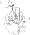
- FIG. 1 illustrates a surgical system for navigating a surgical instrument to an area of interest in accordance with the present disclosure and generally identified by reference numeral 10.
- the surgical system 10 includes an endoscope or catheter 100, a workstation 20 operably coupled to the endoscope or catheter 100, and a Cone Beam Computed Tomography (CBCT) machine 50 operably coupled to the workstation 20.
- CBCT Cone Beam Computed Tomography
- the patient is shown lying on an operating table 60 with the endoscope or catheter 100 inserted through the patient's mouth and into the patient's airways, although it is contemplated that the endoscope or catheter 100 may be inserted into any suitable body cavity of the patient, depending upon the procedure being performed.
- the workstation 20 includes a computer 22 and a display 24 that is configured to display one or more user interfaces 26 and 28.
- the workstation 20 may be a desktop computer or a tower configuration with the display 24 or may be a laptop computer or other computing device.
- the workstation 20 includes a processor 30 which executes software stored in a memory 32.
- the memory 32 may store video or other imaging data captured by the endoscope or catheter 100 or pre-procedure images from, for example, a computer-tomography (CT) scan, Positron emission tomography (PET), Magnetic Resonance Imaging (MRI), Cone-Beam CT, amongst others.
- CT computer-tomography
- PET Positron emission tomography
- MRI Magnetic Resonance Imaging
- Cone-Beam CT Cone-Beam CT
- the display 24 may be incorporated into a head mounted display such as an augmented reality (AR) headset such as the HoloLens offered by Microsoft Corp.
- AR augmented reality
- a network interface 36 enables the workstation 20 to communicate with a variety of other devices and systems via the Internet.
- the network interface 36 may connect the workstation 20 to the Internet via a wired or wireless connection. Additionally, or alternatively, the communication may be via an ad-hoc Bluetooth° or wireless networks enabling communication with a wide-area network (WAN) and/or a local area network (LAN).
- the network interface 36 may connect to the Internet via one or more gateways, routers, and network address translation (NAT) devices.
- the network interface 36 may communicate with a cloud storage system 38, in which further image data and videos may be stored.
- the cloud storage system 38 may be remote from or on the premises of the hospital such as in a control or hospital information technology room.
- An input device 40 receives inputs from an input device such as a keyboard, a mouse, voice commands, amongst others.
- An output module 42 connects the processor 30 and the memory 32 to a variety of output devices such as the display 24. It is envisioned that the output module 42 may include any connectivity port or bus, such as, for example, parallel ports, serial ports, universal serial busses (USB), or any other similar connectivity port known to those skilled in the art.
- the workstation 20 may include its own display 44, which may be touchscreen display.
- the network interface 36 may couple the workstation 20 to a Hospital Information System (HIS) to enable the review of patient information.
- the workstation 20 includes a synthesizer which communicates with the HIS either directly or through a cloud computing network via a hardwired connection or wirelessly.
- Information accessible by the system includes information stored on a Picture Archiving and Communication system (PACS), a Radiology Information System (RIS), an Electronic Medical Records System (EMR), a Laboratory Information System (LIS), and in embodiments, a Cost and Inventory System (CIS), wherein each of which communicates with the HIS.
- PCS Picture Archiving and Communication system
- RIS Radiology Information System
- EMR Electronic Medical Records System
- LIS Laboratory Information System
- CIS Cost and Inventory System
- the patient information may be obtained from any other suitable source, such as private office, compact-disc (CD) or other storage medium, etc.
- the system 10 includes a Patient/Surgeon Interface System or Synthesizer which enables communication with the HIS and its associated database. Using information gathered from the HIS, an Area of Interest (AOI) is able to be identified illustrating the effects of lung disease, and in embodiments, the software application associated with the synthesizer may be able to automatically identify areas of interest and present these identified areas to a clinician for review via the user interface 26.
- AOI Area of Interest
- pre-procedure image data gathered from the HIS is processed by the software application to generate a three-dimensional (3D) reconstruction of the patient's lungs, and using medical information gathered from the HIS, such as, for example, prior surgical procedures, diagnosis of common lung conditions such as Chronic Pulmonary Obstruction Disorder (COPD), and the location of common structures within the patient's body cavity, the software application generates a 3D model of the patient's lungs incorporating this information.
- the system 10 may facilitate an approach of a medical device to the target area using Electromagnetic Navigation (EMN) and for determining the location of a medical device with respect to the AOI.
- ENM Electromagnetic Navigation
- EMN system is the ILLUMISITE system currently sold by Medtronic PLC, though other systems for intraluminal navigation are considered within the scope of the disclosure including shape sensing technology which detect the shape of the distal portion of the catheter and match that shape to the shape of the luminal network in a 3D model.
- the CBCT machine 50 may be a fixed CBCT machine or a mobile CBCT machine.
- the fixed CBCT machine 50 is utilized to scan the patient during the surgical procedure but before the endoscope or catheter 100 is inserted within the patient's airways. In this manner, the patient is sedated or otherwise under anesthesia to ensure that the patient is generally immobilized during the scan performed by the fixed CBCT machine 50. Once the scan has been completed, the images captured by the fixed CBCT machine 50 are saved on a memory associated with fixed CBCT machine 50.
- the images captured by the fixed CBCT machine 50 and saved on the memory may be transferred to the workstation 20 via any suitable means, such as via the internet or intranet (e.g., PACS, etc.), via computer readable storage media (e.g., memory stick, CD-ROM, etc.), amongst others.
- any suitable means such as via the internet or intranet (e.g., PACS, etc.), via computer readable storage media (e.g., memory stick, CD-ROM, etc.), amongst others.
- a planning phase for generating and viewing a 3D model of the patient's anatomy, enabling the identification of target tissue ("TT") on the 3D model (automatically, semi-automatically, or manually), and in embodiments, allowing for the selection of a pathway ("PW") through the patient's anatomy to the target tissue.
- target tissue TT
- PW pathway
- One example of such an application is the ILLUMISITE° planning and navigation suites currently marketed by Medtronic.
- the 3D model may be displayed on the display 24 or another suitable display (not shown) associated with the controller 20, or in any other suitable fashion.
- various views of the 3D model may be provided and/or the 3D model may be manipulated to facilitate identification of target tissue on the 3D model and/or selection of a suitable pathway to the target tissue.
- the endoscope or catheter 100 With the pathway to the target tissue selected, the endoscope or catheter 100 is inserted within the patient's airways and the detected location and/or images obtained by the endoscope or catheter 100 within the patient's airways is automatically registered to the 3D model.
- the 3D model generated from the images acquired by the fixed CBCT machine 50 can be utilized to update or otherwise correct a 3D model generated from the pre-procedure images.
- the navigation of the endoscope or catheter 100 to the target tissue is completed using up to date information regarding the condition of the patient's lungs and reduces the need to perform additional intra-operative imaging to verify the location of the endoscope or catheter 100 within patient's airways during navigation to the target tissue and/or before treatment of the target tissue.
- the 3D model or images obtained by the fixed CBCT machine 50 may be overlaid or otherwise associated with an intra-operative image (e.g., fixed CBCT machine 50 images, images captured by the endoscope or catheter 100, fluoroscopic images, etc.).
- an intra-operative image e.g., fixed CBCT machine 50 images, images captured by the endoscope or catheter 100, fluoroscopic images, etc.
- the software application utilizes pre-procedure image data stored on the memory 32 or via the HIS and is processed by the software application to generate a three-dimensional (3D) reconstruction of the patient's lungs, identify target tissue on the 3D model (automatically, semi-automatically, or manually), and in embodiments, allowing for the selection of a pathway ("PW") through the patient's anatomy to the target tissue.
- PW a pathway
- the endoscope or catheter 100 is inserted within the patient's airways and the detected location of the endoscope or catheter 100 within the patient's airways is automatically registered to the 3D model.
- the endoscope or catheter 100 is then navigated to a portion of the lobe of the patient's lung in which the target tissue is located.
- the endoscope or catheter 100 may be manually navigated to the lobe in which the target tissue is located without the aid of a navigation tool.
- intra-procedure images are obtained from a mobile CBCT machine 50 and transferred to the workstation 20.
- the application generates a 3D model of the patient's anatomy using the intra-procedure images obtained from the mobile CBCT machine 50.
- the software application enables a user to enter the planning phase to identify of target tissue ("TT") on the 3D model (automatically, semi-automatically, or manually), and in embodiments, may allow for the selection of a pathway ("PW”) through the patient's anatomy to the target tissue.
- TT target tissue
- PW pathway
- the 3D model generated from the images obtained by the mobile CBCT machine 50 is registered (either manually or automatically) to the real time images obtained by the endoscope or catheter 100, or in embodiments, updates or otherwise replaces the 3D model generated from the pre-procedure image data and navigation to the target tissue is completed using the updated 3D model.
- the software application permits the user to select and/or mark the location of the endoscope within the 3D model generated from the imaged obtained by the intraoperative mobile CBCT machine 50 to updated and/or correct differences between the initial 3D model generated from the pre-procedure images and the intra-operative images obtained by the mobile CBCT machine 50.
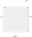
- the patient is laying on a two-dimensional (2D) grid structure of sphere markers 220 including sphere-shaped markers, such as sphere markers 230a and 230b, arranged in a two-dimensional grid pattern.
- the endoscope or catheter 100 is manually navigated within the patient's airways without the use of 3D navigation to the lobe of the patient's lungs in which the target tissue is located (the target lobe).
- the mobile CBCT machine 50 is utilized to capture an image of the patient's lungs from an anteroposterior (AP) direction to identify an angle of the mobile CBCT machine 50 relative to the operating table 60.
- AP anteroposterior
- the CBCT machine 50 (either fixed or mobile) includes a narrower scan angle as compared to fluoroscopic imaging, and therefore, it is envisioned that the 2D grid structure may include fewer sphere markers 230a, 230b to decrease the number of artifacts present within the 3D model generated from the images obtained by the mobile CBCT machine 50.
- the mobile CBCT machine 50 is utilized to obtain a plurality of images of the patient's anatomy and generate a 3D model, as described hereinabove.
- the 3D model may be displayed to the user on the user interface 26 and the user is permitted to mark or otherwise indicate a position of the endoscope or catheter 100 within the images obtained by the mobile CBCT machine 50. Although generally described as being performed manually, it is envisioned that marking the location of the endoscope or catheter 100 within the intra-procedure images obtained by the mobile CBCT machine 50 may be automated by the software application.
- the position of the endoscope or catheter 100 is registered to the 3D model (manually or automatically) and navigation to the target tissue is continued.
- one or more further scans by the mobile CBCT machine 50 to further update and/or confirm the position of the endoscope or catheter 100 within the patient's airways or relative to the target tissue.
- the endoscope or catheter 100 may be navigated to the target lobe utilizing a 3D model formed from pre-procedure images obtained by the system 10, as described in further detail hereinabove. It is envisioned that the user may choose to manually navigate the endoscope or catheter 100 to the target lobe or may utilize a navigation aid utilizing the 3D model generated from pre-procedure images.
- the mobile CBCT machine 50 may be utilized to capture an intra-operative 2D video of the surgical site and generate a composite utilizing tomosynthesis. Utilizing a volume reconstructed from tomosynthesis of the 2D video, the location of the catheter within the images is identified (manually or automatically) and registration is completed.
- the 2D video captured by the mobile CBCT machine 50 may be captured during navigation of the endoscope or catheter 100 through the patient's airways using a 3D model generated using pre-procedure images.
- the 2D video is continuously displayed to the user during navigation to provide real-time corrections of the location of the endoscope or catheter 100 displayed on the 3D model. It is envisioned that the user may be able to provide inputs on the user interface 26 to identify a path through the patient's airways to reach the target tissue. In this manner, the software application utilizes the user inputs to create a pathway through the patient's airways corresponding to the user's inputs on the user interface 26.
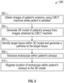
- a method of navigating a surgical instrument to an area of interest is illustrated and generally identified by reference numeral 300.
- images of the patient's lungs are obtained using the CBCT machine 50 while the patient is sedated or otherwise under anesthesia.
- a 3D model of the patient's airways and/or lungs is generated using the images obtained by the CBCT machine 50.
- target tissue is identified within the 3D model and a pathway to the target tissue is identified and displayed to the user on the user interface 26.
- the endoscope or catheter 100 is advanced within the patient's airways in step 308.
- the location of the endoscope or catheter 100 is registered to the 3D model, and in step 312, the endoscope or catheter 100 is navigated to the area of interest.
- step 402 an area of interest is identified within the patient's lungs using pre-procedure images.
- step 404 the endoscope or catheter 100 is advanced within the patient's airways to a lobe of the patient's lungs in which the area of interest is located.
- the patient is imaged using the CBCT machine 50 in step 406.
- a 3D model of the patient's lungs is generated and a pathway to the identified area of interest is selected in step 408.
- step 410 the position of the endoscope or catheter 100 within the target lobe is registered to the 3D model, and in step 412, the endoscope or catheter 100 is navigated to the area of interest.
- FIG. 7 yet another embodiment of a method of navigating a surgical instrument to an area of interest is illustrated and generally identified by reference numeral 500.
- a 3D model of the patient's lungs is generated from pre-procedure images and an area of interest is identified within the 3D model.
- the endoscope or catheter 100 is advanced within the patient's airways and navigated to the identified area of interest. With the endoscope or catheter 100 located adj acent the area of interest, the patient's anatomy is imaged with the CBCT machine 50 in step 506. The images captured by the CBCT machine 50 are reviewed and in step 508, the location of the endoscope or catheter 100 and the area of interest is marked or otherwise identified in the user interface 26.
- step 510 the system corrects the 3D model generated with pre-procedure images using the marked locations of the endoscope or catheter 100 and the area of interest and in step 512, the endoscope is re-positioned relative to the area of interest and the area of interest is treated.
- step 602 the endoscope or catheter 100 is navigated to the target lobe manually and without assistance of guidance.
- step 604 an anteroposterior image of the patient's lungs is obtained by the CBCT machine 50 and in step 606, the CBCT machine 50 is centered and an angle of the CBCT machine 50 relative to the bed 60 is identified using the (2D) grid structure of sphere markers 220.
- step 608 the patient's lungs are imaged using the CBCT machine 50.
- the intra-procedure images captured by the CBCT machine 50 are reviewed and the position of the endoscope or catheter 100 and the area of interest within the intra-procedure images are marked or otherwise indicated in the user interface 26 in step 610.
- the position of the endoscope or catheter 100 and the area of interest are registered to a 3D model generated from the intra-procedural images and in step 614, the endoscope or catheter 100 is navigated to the area of interest using the 3D model.
- step 616 it is determined if a further intra-operative scan using the CBCT machine 50 is necessary, and if so, the patient's anatomy is imaged a second time using the CBCT machine 50 to confirm the location of the endoscope or catheter 100 relative to the area of interest in step 618. With the location of the endoscope or catheter 100 relative to the area of interest confirmed, the area of interest is treated in step 620. If no further scan is required, step 618 is skipped and the area of interest is treated in step 620.
- FIG. 9 another embodiment of a method of navigating a surgical instrument to an area of interest is illustrated and generally identified by reference numeral 700.
- a 3D model is generated from pre-procedure images and an area of interest, and a pathway thereto, is identified in the 3D model.
- an anteroposterior image of the patient's lungs is obtained by the CBCT machine 50 and in step 706, the CBCT machine 50 is centered and an angle of the CBCT machine 50 relative to the bed 60 is identified using the (2D) grid structure of sphere markers 220.
- the patient's lungs are imaged using the CBCT machine 50.
- step 710 the location of the endoscope or catheter 100 and the area of interest is marked or otherwise identified in the intra-procedure images captured by the CBCT machine 50 using the user interface 26.
- step 712 the pre-procedure images and the intra-procedure images are registered with one another, and in step 714, the endoscope or catheter 100 is navigated to the area of interest.
- step 716 it is determined if a further intra-procedural scan using the CBCT machine 50 is needed, and if so, the patient's anatomy is imaged a second time using the CBCT machine 50 to confirm the location of the endoscope or catheter 100 relative to the area of interest in step 718. With the location of the endoscope or catheter 100 relative to the area of interest confirmed, the area of interest is treated in step 720. If no further scan is required, step 718 is skipped and the area of interest is treated in step 720.
- a 3D model is generated from pre-procedure images and an area of interest, and a pathway thereto, is identified in the 3D model.
- the endoscope or catheter 100 is navigated within the patient's airways using the plan generated in step 802.
- a 2D video stream is captured by the CBCT machine 50 and transmitted to the user interface 26 for review by the user.
- step 808 Using the 2D video stream, in step 808, a 3D volume of the patient's anatomy is generated and the location of the endoscope or catheter 100 and the area of interest is marked or otherwise indicated in the 3D volume using the user interface 26 in step 810. In step 812, the location of the endoscope or catheter 100 and the area of interest is locally registered to the 3D volume.
- a 3D model of the patient's lungs is generated from pre-procedure CT images and an area of interest, and a pathway thereto, is identified in the 3D model.
- a 2D video stream is captured by the CBCT machine 50 and transmitted to the user interface 26 for review by the user.
- the endoscope or catheter 100 is navigated to the area of interest within the patient's airways utilizing the 3D model of the patient's lungs and the 2D video stream captured by the CBCT machine 50.
- FIG. 12 another embodiment of a method of navigating a surgical instrument to an area of interest is illustrated and generally identified by reference numeral 1000.
- a 3D model of the patient's lungs is generated from pre-procedure CT images and an area of interest, and a pathway thereto, is identified in the 3D model.
- the endoscope or catheter 100 is navigated within the patient's lungs using the 3D model of the patient's lungs.
- the patient is scanned using the CBCT machine 50 and the intra-procedure images captured by the CBCT machine 50 are displayed on the user interface 26 in step 1008.
- step 1008 using the user interface 26, inputs on the user interface are utilized to identify a pathway through the patient's luminal network from the identified location of the endoscope or catheter 100 within the intra-procedure images to the area of interest.
- step 1010 the endoscope or catheter 100 is navigated to the area of interface using the pathway identified in the intra-procedure images on the user interface 26.
- the memory 32 may include any non-transitory computer-readable storage media for storing data and/or software including instructions that are executable by the processor 30 and which control the operation of the controller 20 and, in some embodiments, may also control the operation of the endoscope or catheter 100.
- memory 32 may include one or more storage devices such as solid-state storage devices, e.g., flash memory chips.
- the memory 32 may include one or more mass storage devices connected to the processor 30 through a mass storage controller (not shown) and a communications bus (not shown).
- computer-readable storage media can be any available media that can be accessed by the processor 30. That is, computer readable storage media may include non-transitory, volatile and non-volatile, removable and nonremovable media implemented in any method or technology for storage of information such as computer-readable instructions, data structures, program modules or other data.
- computer-readable storage media may include RAM, ROM, EPROM, EEPROM, flash memory or other solid-state memory technology, CD-ROM, DVD, Blu-Ray or other optical storage, magnetic cassettes, magnetic tape, magnetic disk storage or other magnetic storage devices, or any other medium which may be used to store the desired information, and which may be accessed by the controller 20.
Landscapes
- Health & Medical Sciences (AREA)
- Life Sciences & Earth Sciences (AREA)
- Engineering & Computer Science (AREA)
- Medical Informatics (AREA)
- Surgery (AREA)
- Nuclear Medicine, Radiotherapy & Molecular Imaging (AREA)
- Public Health (AREA)
- General Health & Medical Sciences (AREA)
- Veterinary Medicine (AREA)
- Animal Behavior & Ethology (AREA)
- Molecular Biology (AREA)
- Heart & Thoracic Surgery (AREA)
- Biomedical Technology (AREA)
- Pathology (AREA)
- Radiology & Medical Imaging (AREA)
- Physics & Mathematics (AREA)
- Biophysics (AREA)
- High Energy & Nuclear Physics (AREA)
- Optics & Photonics (AREA)
- Theoretical Computer Science (AREA)
- Robotics (AREA)
- Computer Vision & Pattern Recognition (AREA)
- Oral & Maxillofacial Surgery (AREA)
- Pulmonology (AREA)
- Gynecology & Obstetrics (AREA)
- General Physics & Mathematics (AREA)
- Apparatus For Radiation Diagnosis (AREA)
Abstract
Description
- The present disclosure relates to the field of navigation of medical devices within a patient, and in particular, planning a pathway through a luminal network of a patient and navigating medical devices to a target.
- There are several commonly applied medical methods, such as endoscopic procedures or minimally invasive procedures, for treating various maladies affecting organs including the liver, brain, heart, lungs, gall bladder, kidneys, and bones. Often, one or more imaging modalities, such as magnetic resonance imaging (MRI), ultrasound imaging, computed tomography (CT), cone-beam computed tomography (CBCT) or fluoroscopy (including 3D fluoroscopy) are employed by clinicians to identify and navigate to areas of interest within a patient and ultimately a target for biopsy or treatment. In some procedures, pre-operative scans may be utilized for target identification and intraoperative guidance. However, real-time imaging may be required to obtain a more accurate and current image of the target area. Furthermore, real-time image data displaying the current location of a medical device with respect to the target and its surroundings may be needed to navigate the medical device to the target in a safe and accurate manner (e.g., without causing damage to other organs or tissue).
- For example, an endoscopic approach has proven useful in navigating to areas of interest within a patient. To enable the endoscopic approach endoscopic navigation systems have been developed that use previously acquired MRI data or CT image data to generate a three-dimensional (3D) rendering, model, or volume of the particular body part such as the lungs.
- In some applications, the acquired MRI data or CT Image data may be acquired during the procedure (perioperatively). The resulting volume generated from the MRI scan or CT scan is then utilized to create a navigation plan to facilitate the advancement of the endoscope (or other suitable medical device) within the patient anatomy to an area of interest. In some cases, the volume generated may be used to update a previously created navigation plan. A locating or tracking system, such as an electromagnetic (EM) tracking system, or fiber-optic shape sensing system may be utilized in conjunction with, for example, CT data, to facilitate guidance of the endoscope to the area of interest.
- However, CT-to-body divergence can cause inaccuracies in navigation using locating or tracking systems, leading to the use of fluoroscopic navigation to identify a current position of the medical device and correcting the location of the medical device in the 3D model. As can be appreciated, these inaccuracies can lead to increased surgical times to correct the real-time position of the medical device within the 3D models and the use of fluoroscopy leads to additional set-up time and radiation exposure.
- In accordance with the present disclosure, a method of performing a surgical procedure includes obtaining images of a patient's anatomy using a cone beam computed tomography machine while the patient is sedated, identifying an area of interest in the images obtained by the cone beam computed tomography machine, identifying a pathway to the identified area of interest using the images obtained by the cone beam computed tomography machine, and navigating a catheter within the patient's airways to the identified area of interest.
- In aspects, obtaining the images of the patient's anatomy may include obtaining the images of a patient's anatomy using a fixed cone beam computed tomography machine while the patient is sedated.
- In other aspects, obtaining the images of the patient's anatomy may include obtaining the images of a patient's anatomy using a mobile cone beam computed tomography machine while the patient is sedated.
- In certain aspects, the method may include generating a three-dimensional model of the patient's anatomy from the images obtained by the cone beam computed tomography machine.
- In aspects, identifying the area of interest may include identifying the area of interest within the three-dimensional model of the patient's anatomy.
- In certain aspects, the method may include registering a location of the catheter within the patient's anatomy to the images obtained by the cone beam computed tomography machine.
- In other aspects, obtaining images of the patient's anatomy may include obtaining images of the patient's anatomy using the cone beam computed tomography machine while the patient is sedated and before advancement of the catheter within the patient's body cavity.
- In accordance with another aspect of the present disclosure, a method of performing a surgical procedure includes navigating a catheter to a lobe of a patient's lung including an area of interest, obtaining images of the patient's anatomy using a cone beam computed tomography machine, identifying the area of interest in the images obtained by the cone beam computed tomography machine, identifying a pathway to the area of interest using the images obtained by the cone beam computed tomography machine, and navigating the catheter to the area of interest using the identified pathway.
- In aspects, obtaining the images of the patient's anatomy may include obtaining the images of a patient's anatomy using a fixed cone beam computed tomography machine.
- In other aspects, obtaining the images of the patient's anatomy may include obtaining the images of a patient's anatomy using a mobile cone beam computed tomography machine.
- In certain aspects, the method may include generating a three-dimensional model of the patient's anatomy from the images obtained by the cone beam computed tomography machine.
- In other aspects, identifying the area of interest may include identifying the area of interest within the three-dimensional model of the patient's anatomy.
- In aspects, the method may include registering a location of the catheter within the patient's anatomy to the images obtained by the cone beam computed tomography machine.
- In certain aspects, the method may include obtaining an anteroposterior image of the patient's anatomy using the cone beam computed tomography machine and identifying an angle of the cone beam computed tomography machine when the anteroposterior image was obtained.
- In other aspects, the method may include identifying a location of a portion of the catheter within the images obtained by the cone beam computed tomography machine.
- In aspects, the method may include registering the identified location of the catheter to the images obtained by the cone beam computed tomography machine.
- In accordance with another aspect of the present disclosure, a system for performing a surgical procedure includes a cone beam computed tomography machine, a catheter configured to be navigated within a patient's airways, and a controller operably coupled to the cone beam computed tomography machine, the controller including a memory and a processor, the memory storing instructions, which when executed by the processor cause the processor to obtain images of a patient's anatomy using the cone beam computed tomography machine while the patient is sedated, identify an area of interest in the images obtained by the cone beam computed tomography machine, identify a pathway to the identified area of interest using the images obtained by the cone beam computed tomography machine, and aid navigation of the catheter within the patient's airways to the identified area of interest using the identified pathway.
- In aspects, the cone beam computed tomography machine is a fixed cone beam computed tomography machine.
- In other aspects, the cone beam computed tomography machine is a mobile cone beam computed tomography machine.
- In certain aspects, the instructions, when executed by the processor, may cause the processor to obtain images of the patient's anatomy using the cone beam computed tomography machine while the patient is sedated and before advancement of the catheter within the patient's body cavity.
- Various aspects and embodiments of the disclosure are described hereinbelow with references to the drawings, wherein:
-
FIG. 1 is a schematic view of a surgical system provided in accordance with the present disclosure; -
FIG. 2 is a schematic view of a controller of the surgical system ofFIG. 1 ; -
FIG. 3 is a schematic illustration of a two-dimensional grid structure of markers in accordance with the present disclosure; -
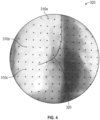
FIG. 4 is an exemplary image of a surgical site including the two-dimensional grid structure ofFIG. 3 illustrated captured therein; -
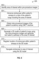
FIG. 5 is a flow diagram illustrating a method of performing a surgical procedure in accordance with aspects of the present disclosure; -
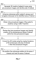
FIG. 6 is a flow diagram illustrating another method of performing a surgical procedure in accordance with aspects of the present disclosure; -
FIG. 7 is a flow diagram illustrating yet another method of performing a surgical procedure in accordance with aspects of the present disclosure; -
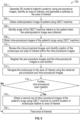
FIG. 8 is a flow diagram illustrating still another method of performing a surgical procedure in accordance with aspects of the present disclosure; -
FIG. 9 is a flow diagram illustrating another method of performing a surgical procedure in accordance with aspects of the present disclosure; -
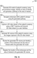
FIG. 10 is a flow diagram illustrating yet another method of performing a surgical procedure in accordance with aspects of the present disclosure; -
FIG. 11 is a flow diagram illustrating another method of performing a surgical procedure in accordance with aspects of the present disclosure; and -
FIG. 12 is a flow diagram illustrating still another method of performing a surgical procedure in accordance with aspects of the present disclosure. - The present disclosure is directed to surgical imaging system, and more particularly, to system and methods for assisting a clinician in navigation of endoscopes, catheters, and tools to area of interest or targets within a patient for biopsy and therapy while reducing the number of times a patient must be imaged and increasing the accuracy of the navigational model. The system and methods include utilizing fixed or mobile cone beam computed tomography (CBCT) machines to obtain intra-procedural images of the patient's anatomy. The intra-procedural images can be used in lieu of pre-procedural images or otherwise update models, pathways, and/or plans generated using pre-procedural images. It is envisioned that inputs may be made on a user interface to identify a position of the endoscope and/or area of interest within the intra-procedural images to increase the accuracy of a registration between the position of the endoscope and/or area of interest within the model generated from the intra-procedural images. Although generally described with reference to the lung, it is contemplated that the systems and methods described herein may be used with any structure within the patient's body, such as the liver, kidney, prostate, gynecological, amongst others.
- Turning now to the drawings,
FIG. 1 illustrates a surgical system for navigating a surgical instrument to an area of interest in accordance with the present disclosure and generally identified byreference numeral 10. Thesurgical system 10 includes an endoscope orcatheter 100, aworkstation 20 operably coupled to the endoscope orcatheter 100, and a Cone Beam Computed Tomography (CBCT)machine 50 operably coupled to theworkstation 20. The patient is shown lying on an operating table 60 with the endoscope orcatheter 100 inserted through the patient's mouth and into the patient's airways, although it is contemplated that the endoscope orcatheter 100 may be inserted into any suitable body cavity of the patient, depending upon the procedure being performed. - Continuing with
FIG. 1 and with additional reference toFIG. 2 , theworkstation 20 includes acomputer 22 and adisplay 24 that is configured to display one ormore user interfaces workstation 20 may be a desktop computer or a tower configuration with thedisplay 24 or may be a laptop computer or other computing device. Theworkstation 20 includes aprocessor 30 which executes software stored in amemory 32. Thememory 32 may store video or other imaging data captured by the endoscope orcatheter 100 or pre-procedure images from, for example, a computer-tomography (CT) scan, Positron emission tomography (PET), Magnetic Resonance Imaging (MRI), Cone-Beam CT, amongst others. In addition, thememory 32 may store one or more applications 34 to be executed on theprocessor 30. Through not explicitly illustrated, thedisplay 24 may be incorporated into a head mounted display such as an augmented reality (AR) headset such as the HoloLens offered by Microsoft Corp. - A network interface 36 enables the
workstation 20 to communicate with a variety of other devices and systems via the Internet. The network interface 36 may connect theworkstation 20 to the Internet via a wired or wireless connection. Additionally, or alternatively, the communication may be via an ad-hoc Bluetooth° or wireless networks enabling communication with a wide-area network (WAN) and/or a local area network (LAN). The network interface 36 may connect to the Internet via one or more gateways, routers, and network address translation (NAT) devices. The network interface 36 may communicate with a cloud storage system 38, in which further image data and videos may be stored. The cloud storage system 38 may be remote from or on the premises of the hospital such as in a control or hospital information technology room. An input device 40 receives inputs from an input device such as a keyboard, a mouse, voice commands, amongst others. An output module 42 connects theprocessor 30 and thememory 32 to a variety of output devices such as thedisplay 24. It is envisioned that the output module 42 may include any connectivity port or bus, such as, for example, parallel ports, serial ports, universal serial busses (USB), or any other similar connectivity port known to those skilled in the art. In embodiments, theworkstation 20 may include itsown display 44, which may be touchscreen display. - In embodiments, the network interface 36 may couple the
workstation 20 to a Hospital Information System (HIS) to enable the review of patient information. As such, theworkstation 20 includes a synthesizer which communicates with the HIS either directly or through a cloud computing network via a hardwired connection or wirelessly. Information accessible by the system includes information stored on a Picture Archiving and Communication system (PACS), a Radiology Information System (RIS), an Electronic Medical Records System (EMR), a Laboratory Information System (LIS), and in embodiments, a Cost and Inventory System (CIS), wherein each of which communicates with the HIS. Although generally described as utilizing the HIS, it is envisioned that the patient information may be obtained from any other suitable source, such as private office, compact-disc (CD) or other storage medium, etc. - The
system 10 includes a Patient/Surgeon Interface System or Synthesizer which enables communication with the HIS and its associated database. Using information gathered from the HIS, an Area of Interest (AOI) is able to be identified illustrating the effects of lung disease, and in embodiments, the software application associated with the synthesizer may be able to automatically identify areas of interest and present these identified areas to a clinician for review via theuser interface 26. In embodiments, pre-procedure image data gathered from the HIS is processed by the software application to generate a three-dimensional (3D) reconstruction of the patient's lungs, and using medical information gathered from the HIS, such as, for example, prior surgical procedures, diagnosis of common lung conditions such as Chronic Pulmonary Obstruction Disorder (COPD), and the location of common structures within the patient's body cavity, the software application generates a 3D model of the patient's lungs incorporating this information. In embodiments, thesystem 10 may facilitate an approach of a medical device to the target area using Electromagnetic Navigation (EMN) and for determining the location of a medical device with respect to the AOI. One such EMN system is the ILLUMISITE system currently sold by Medtronic PLC, though other systems for intraluminal navigation are considered within the scope of the disclosure including shape sensing technology which detect the shape of the distal portion of the catheter and match that shape to the shape of the luminal network in a 3D model. - In embodiments, the
CBCT machine 50 may be a fixed CBCT machine or a mobile CBCT machine. In one embodiment, the fixedCBCT machine 50 is utilized to scan the patient during the surgical procedure but before the endoscope orcatheter 100 is inserted within the patient's airways. In this manner, the patient is sedated or otherwise under anesthesia to ensure that the patient is generally immobilized during the scan performed by the fixedCBCT machine 50. Once the scan has been completed, the images captured by the fixedCBCT machine 50 are saved on a memory associated withfixed CBCT machine 50. It is envisioned that the images captured by the fixedCBCT machine 50 and saved on the memory may be transferred to theworkstation 20 via any suitable means, such as via the internet or intranet (e.g., PACS, etc.), via computer readable storage media (e.g., memory stick, CD-ROM, etc.), amongst others. - With the images captured by the fixed
CBCT machine 50 received by theworkstation 20, a planning phase for generating and viewing a 3D model of the patient's anatomy, enabling the identification of target tissue ("TT") on the 3D model (automatically, semi-automatically, or manually), and in embodiments, allowing for the selection of a pathway ("PW") through the patient's anatomy to the target tissue. One example of such an application is the ILLUMISITE° planning and navigation suites currently marketed by Medtronic. The 3D model may be displayed on thedisplay 24 or another suitable display (not shown) associated with thecontroller 20, or in any other suitable fashion. Using thecontroller 20, various views of the 3D model may be provided and/or the 3D model may be manipulated to facilitate identification of target tissue on the 3D model and/or selection of a suitable pathway to the target tissue. With the pathway to the target tissue selected, the endoscope orcatheter 100 is inserted within the patient's airways and the detected location and/or images obtained by the endoscope orcatheter 100 within the patient's airways is automatically registered to the 3D model. - In embodiments, the 3D model generated from the images acquired by the fixed
CBCT machine 50 can be utilized to update or otherwise correct a 3D model generated from the pre-procedure images. In this manner, the navigation of the endoscope orcatheter 100 to the target tissue is completed using up to date information regarding the condition of the patient's lungs and reduces the need to perform additional intra-operative imaging to verify the location of the endoscope orcatheter 100 within patient's airways during navigation to the target tissue and/or before treatment of the target tissue. It is envisioned that the 3D model or images obtained by the fixedCBCT machine 50 may be overlaid or otherwise associated with an intra-operative image (e.g., fixedCBCT machine 50 images, images captured by the endoscope orcatheter 100, fluoroscopic images, etc.). - In another embodiment, before the surgical procedure begins, the software application utilizes pre-procedure image data stored on the
memory 32 or via the HIS and is processed by the software application to generate a three-dimensional (3D) reconstruction of the patient's lungs, identify target tissue on the 3D model (automatically, semi-automatically, or manually), and in embodiments, allowing for the selection of a pathway ("PW") through the patient's anatomy to the target tissue. With the pathway to the target tissue selected, the endoscope orcatheter 100 is inserted within the patient's airways and the detected location of the endoscope orcatheter 100 within the patient's airways is automatically registered to the 3D model. The endoscope orcatheter 100 is then navigated to a portion of the lobe of the patient's lung in which the target tissue is located. Although generally described as utilizing a 3D model to aid navigation of the endoscope orcatheter 100 to the lobe in which the target tissue is located, it is envisioned that the endoscope orcatheter 100 may be manually navigated to the lobe in which the target tissue is located without the aid of a navigation tool. - Once the endoscope is located within the lobe in which the target tissue is located, intra-procedure images are obtained from a
mobile CBCT machine 50 and transferred to theworkstation 20. The application generates a 3D model of the patient's anatomy using the intra-procedure images obtained from themobile CBCT machine 50. The software application enables a user to enter the planning phase to identify of target tissue ("TT") on the 3D model (automatically, semi-automatically, or manually), and in embodiments, may allow for the selection of a pathway ("PW") through the patient's anatomy to the target tissue. With the pathway to the target tissue selected, the 3D model generated from the images obtained by themobile CBCT machine 50 is registered (either manually or automatically) to the real time images obtained by the endoscope orcatheter 100, or in embodiments, updates or otherwise replaces the 3D model generated from the pre-procedure image data and navigation to the target tissue is completed using the updated 3D model. - In embodiments, the software application permits the user to select and/or mark the location of the endoscope within the 3D model generated from the imaged obtained by the intraoperative
mobile CBCT machine 50 to updated and/or correct differences between the initial 3D model generated from the pre-procedure images and the intra-operative images obtained by themobile CBCT machine 50. - With additional reference to
FIGS. 3 and4 , in an embodiment, the patient is laying on a two-dimensional (2D) grid structure ofsphere markers 220 including sphere-shaped markers, such assphere markers catheter 100 is manually navigated within the patient's airways without the use of 3D navigation to the lobe of the patient's lungs in which the target tissue is located (the target lobe). Once the endoscope orcatheter 100 is located within the target lobe, themobile CBCT machine 50 is utilized to capture an image of the patient's lungs from an anteroposterior (AP) direction to identify an angle of themobile CBCT machine 50 relative to the operating table 60. As can be appreciated, the CBCT machine 50 (either fixed or mobile) includes a narrower scan angle as compared to fluoroscopic imaging, and therefore, it is envisioned that the 2D grid structure may includefewer sphere markers mobile CBCT machine 50. With the angle of themobile CBCT machine 50 relative to the operating table 60 known, themobile CBCT machine 50 is utilized to obtain a plurality of images of the patient's anatomy and generate a 3D model, as described hereinabove. The 3D model may be displayed to the user on theuser interface 26 and the user is permitted to mark or otherwise indicate a position of the endoscope orcatheter 100 within the images obtained by themobile CBCT machine 50. Although generally described as being performed manually, it is envisioned that marking the location of the endoscope orcatheter 100 within the intra-procedure images obtained by themobile CBCT machine 50 may be automated by the software application. - With the location of the endoscope or
catheter 100 identified within the intra-procedure images obtained by themobile CBCT machine 50, the position of the endoscope orcatheter 100 is registered to the 3D model (manually or automatically) and navigation to the target tissue is continued. In embodiments, one or more further scans by themobile CBCT machine 50 to further update and/or confirm the position of the endoscope orcatheter 100 within the patient's airways or relative to the target tissue. - In embodiments, rather than manually navigating the endoscope or
catheter 100 to the target lobe, it is envisioned that the endoscope orcatheter 100 may be navigated to the target lobe utilizing a 3D model formed from pre-procedure images obtained by thesystem 10, as described in further detail hereinabove. It is envisioned that the user may choose to manually navigate the endoscope orcatheter 100 to the target lobe or may utilize a navigation aid utilizing the 3D model generated from pre-procedure images. - In some embodiments, during navigation of the endoscope or
catheter 100 within the patient's airways using a 3D model constructed of pre-procedure images, themobile CBCT machine 50 may be utilized to capture an intra-operative 2D video of the surgical site and generate a composite utilizing tomosynthesis. Utilizing a volume reconstructed from tomosynthesis of the 2D video, the location of the catheter within the images is identified (manually or automatically) and registration is completed. In embodiments, the 2D video captured by themobile CBCT machine 50 may be captured during navigation of the endoscope orcatheter 100 through the patient's airways using a 3D model generated using pre-procedure images. The 2D video is continuously displayed to the user during navigation to provide real-time corrections of the location of the endoscope orcatheter 100 displayed on the 3D model. It is envisioned that the user may be able to provide inputs on theuser interface 26 to identify a path through the patient's airways to reach the target tissue. In this manner, the software application utilizes the user inputs to create a pathway through the patient's airways corresponding to the user's inputs on theuser interface 26. - Turning to
FIG. 5 , a method of navigating a surgical instrument to an area of interest is illustrated and generally identified byreference numeral 300. Initially, instep 302 images of the patient's lungs are obtained using theCBCT machine 50 while the patient is sedated or otherwise under anesthesia. Instep 304, a 3D model of the patient's airways and/or lungs is generated using the images obtained by theCBCT machine 50. Using the generated 3D model, instep 306, target tissue is identified within the 3D model and a pathway to the target tissue is identified and displayed to the user on theuser interface 26. With the 3D model generated and the pathway to the target tissue selected, the endoscope orcatheter 100 is advanced within the patient's airways instep 308. Instep 310, the location of the endoscope orcatheter 100 is registered to the 3D model, and in step 312, the endoscope orcatheter 100 is navigated to the area of interest. - With reference to
FIG. 6 , another embodiment of a method of navigating a surgical instrument to an area of interest is illustrated and generally identified byreference numeral 400. Initially, instep 402, an area of interest is identified within the patient's lungs using pre-procedure images. Instep 404, the endoscope orcatheter 100 is advanced within the patient's airways to a lobe of the patient's lungs in which the area of interest is located. Once located within the target lobe, the patient is imaged using theCBCT machine 50 instep 406. Using the images obtained by theCBCT machine 50, a 3D model of the patient's lungs is generated and a pathway to the identified area of interest is selected instep 408. At this point, instep 410, the position of the endoscope orcatheter 100 within the target lobe is registered to the 3D model, and instep 412, the endoscope orcatheter 100 is navigated to the area of interest. - Turning to
FIG. 7 , yet another embodiment of a method of navigating a surgical instrument to an area of interest is illustrated and generally identified byreference numeral 500. Instep 502, a 3D model of the patient's lungs is generated from pre-procedure images and an area of interest is identified within the 3D model. Instep 504, the endoscope orcatheter 100 is advanced within the patient's airways and navigated to the identified area of interest. With the endoscope orcatheter 100 located adj acent the area of interest, the patient's anatomy is imaged with theCBCT machine 50 instep 506. The images captured by theCBCT machine 50 are reviewed and instep 508, the location of the endoscope orcatheter 100 and the area of interest is marked or otherwise identified in theuser interface 26. Instep 510, the system corrects the 3D model generated with pre-procedure images using the marked locations of the endoscope orcatheter 100 and the area of interest and instep 512, the endoscope is re-positioned relative to the area of interest and the area of interest is treated. - With reference to
FIG. 8 , still another embodiment of a method of navigating a surgical instrument to an area of interest is illustrated and generally identified byreference numeral 600. Initially, instep 602, the endoscope orcatheter 100 is navigated to the target lobe manually and without assistance of guidance. Instep 604, an anteroposterior image of the patient's lungs is obtained by theCBCT machine 50 and instep 606, theCBCT machine 50 is centered and an angle of theCBCT machine 50 relative to thebed 60 is identified using the (2D) grid structure ofsphere markers 220. Instep 608, the patient's lungs are imaged using theCBCT machine 50. The intra-procedure images captured by theCBCT machine 50 are reviewed and the position of the endoscope orcatheter 100 and the area of interest within the intra-procedure images are marked or otherwise indicated in theuser interface 26 instep 610. Instep 612, the position of the endoscope orcatheter 100 and the area of interest are registered to a 3D model generated from the intra-procedural images and instep 614, the endoscope orcatheter 100 is navigated to the area of interest using the 3D model. Instep 616, it is determined if a further intra-operative scan using theCBCT machine 50 is necessary, and if so, the patient's anatomy is imaged a second time using theCBCT machine 50 to confirm the location of the endoscope orcatheter 100 relative to the area of interest instep 618. With the location of the endoscope orcatheter 100 relative to the area of interest confirmed, the area of interest is treated instep 620. If no further scan is required,step 618 is skipped and the area of interest is treated instep 620. - Turning to
FIG. 9 , another embodiment of a method of navigating a surgical instrument to an area of interest is illustrated and generally identified byreference numeral 700. Initially, instep 702, a 3D model is generated from pre-procedure images and an area of interest, and a pathway thereto, is identified in the 3D model. Instep 704, an anteroposterior image of the patient's lungs is obtained by theCBCT machine 50 and instep 706, theCBCT machine 50 is centered and an angle of theCBCT machine 50 relative to thebed 60 is identified using the (2D) grid structure ofsphere markers 220. Instep 708, the patient's lungs are imaged using theCBCT machine 50. Instep 710, the location of the endoscope orcatheter 100 and the area of interest is marked or otherwise identified in the intra-procedure images captured by theCBCT machine 50 using theuser interface 26. Instep 712, the pre-procedure images and the intra-procedure images are registered with one another, and instep 714, the endoscope orcatheter 100 is navigated to the area of interest. Instep 716, it is determined if a further intra-procedural scan using theCBCT machine 50 is needed, and if so, the patient's anatomy is imaged a second time using theCBCT machine 50 to confirm the location of the endoscope orcatheter 100 relative to the area of interest instep 718. With the location of the endoscope orcatheter 100 relative to the area of interest confirmed, the area of interest is treated instep 720. If no further scan is required,step 718 is skipped and the area of interest is treated instep 720. - Referring to
FIG. 10 , another embodiment of a method of navigating a surgical instrument to an area of interest is illustrated and generally identified byreference numeral 800. Instep 802, a 3D model is generated from pre-procedure images and an area of interest, and a pathway thereto, is identified in the 3D model. Instep 804, the endoscope orcatheter 100 is navigated within the patient's airways using the plan generated instep 802. Instep 806, a 2D video stream is captured by theCBCT machine 50 and transmitted to theuser interface 26 for review by the user. Using the 2D video stream, instep 808, a 3D volume of the patient's anatomy is generated and the location of the endoscope orcatheter 100 and the area of interest is marked or otherwise indicated in the 3D volume using theuser interface 26 instep 810. Instep 812, the location of the endoscope orcatheter 100 and the area of interest is locally registered to the 3D volume. - With reference to
FIG. 11 , yet another embodiment of a method of navigating a surgical instrument to an area of interest is illustrated and generally identified byreference numeral 900. Instep 902, a 3D model of the patient's lungs is generated from pre-procedure CT images and an area of interest, and a pathway thereto, is identified in the 3D model. Instep 904, a 2D video stream is captured by theCBCT machine 50 and transmitted to theuser interface 26 for review by the user. Instep 906, the endoscope orcatheter 100 is navigated to the area of interest within the patient's airways utilizing the 3D model of the patient's lungs and the 2D video stream captured by theCBCT machine 50. - Turning to
FIG. 12 , another embodiment of a method of navigating a surgical instrument to an area of interest is illustrated and generally identified byreference numeral 1000. Instep 1002, a 3D model of the patient's lungs is generated from pre-procedure CT images and an area of interest, and a pathway thereto, is identified in the 3D model. Instep 1004, the endoscope orcatheter 100 is navigated within the patient's lungs using the 3D model of the patient's lungs. Instep 1006, the patient is scanned using theCBCT machine 50 and the intra-procedure images captured by theCBCT machine 50 are displayed on theuser interface 26 instep 1008. Instep 1008, using theuser interface 26, inputs on the user interface are utilized to identify a pathway through the patient's luminal network from the identified location of the endoscope orcatheter 100 within the intra-procedure images to the area of interest. Instep 1010, the endoscope orcatheter 100 is navigated to the area of interface using the pathway identified in the intra-procedure images on theuser interface 26. - Although described generally hereinabove, it is envisioned that the
memory 32 may include any non-transitory computer-readable storage media for storing data and/or software including instructions that are executable by theprocessor 30 and which control the operation of thecontroller 20 and, in some embodiments, may also control the operation of the endoscope orcatheter 100. In an embodiment,memory 32 may include one or more storage devices such as solid-state storage devices, e.g., flash memory chips. Alternatively, or in addition to the one or more solid-state storage devices, thememory 32 may include one or more mass storage devices connected to theprocessor 30 through a mass storage controller (not shown) and a communications bus (not shown). - Although the description of computer-readable media contained herein refers to solid-state storage, it should be appreciated by those skilled in the art that computer-readable storage media can be any available media that can be accessed by the
processor 30. That is, computer readable storage media may include non-transitory, volatile and non-volatile, removable and nonremovable media implemented in any method or technology for storage of information such as computer-readable instructions, data structures, program modules or other data. For example, computer-readable storage media may include RAM, ROM, EPROM, EEPROM, flash memory or other solid-state memory technology, CD-ROM, DVD, Blu-Ray or other optical storage, magnetic cassettes, magnetic tape, magnetic disk storage or other magnetic storage devices, or any other medium which may be used to store the desired information, and which may be accessed by thecontroller 20. - While several embodiments of the disclosure have been shown in the drawings, it is not intended that the disclosure be limited thereto, as it is intended that the disclosure be as broad in scope as the art will allow and that the specification be read likewise. Therefore, the above description should not be construed as limiting, but merely as exemplifications of embodiments. Those skilled in the art will envision other modifications within the scope and spirit of the claims appended hereto.
- The invention may be described by reference to the following numbered paragraphs:-
- 1. A method of performing a surgical procedure, comprising:
- obtaining images of a patient's anatomy using a cone beam computed tomography machine while the patient is sedated;
- identifying an area of interest in the images obtained by the cone beam computed tomography machine;
- identifying a pathway to the identified area of interest using the images obtained by the cone beam computed tomography machine; and
- navigating a catheter within the patient's airways to the identified area of interest using the identified pathway.
- 2. The method according to paragraph 1, wherein obtaining the images of the patient's anatomy includes obtaining the images of a patient's anatomy using a fixed cone beam computed tomography machine while the patient is sedated.
- 3. The method according to paragraph 1, wherein obtaining the images of the patient's anatomy includes obtaining the images of a patient's anatomy using a mobile cone beam computed tomography machine while the patient is sedated.
- 4. The method according to paragraph 1, further comprising generating a three-dimensional model of the patient's anatomy from the images obtained by the cone beam computed tomography machine.
- 5. The method according to paragraph 4, wherein identifying the area of interest includes identifying the area of interest within the three-dimensional model of the patient's anatomy.
- 6. The method according to paragraph 1, further comprising registering a location of the catheter within the patient's anatomy to the images obtained by the cone beam computed tomography machine.
- 7. The method according to paragraph 1, wherein obtaining images of the patient's anatomy includes obtaining images of the patient's anatomy using the cone beam computed tomography machine while the patient is sedated and before advancement of the catheter within the patient's body cavity.
- 8. A method of performing a surgical procedure, comprising:
- navigating a catheter to a lobe of a patient's lung including an area of interest;
- obtaining images of the patient's anatomy using a cone beam computed tomography machine;
- identifying the area of interest in the images obtained by the cone beam computed tomography machine;
- identifying a pathway to the area of interest using the images obtained by the cone beam computed tomography machine; and
- navigating the catheter to the area of interest using the identified pathway.
- 9. The method according to paragraph 8, wherein obtaining the images of the patient's anatomy includes obtaining the images of a patient's anatomy using a fixed cone beam computed tomography machine.
- 10. The method according to paragraph 8, wherein obtaining the images of the patient's anatomy includes obtaining the images of a patient's anatomy using a mobile cone beam computed tomography machine.
- 11. The method according to paragraph 8, further comprising generating a three-dimensional model of the patient's anatomy from the images obtained by the cone beam computed tomography machine.
- 12. The method according to paragraph 11, wherein identifying the area of interest includes identifying the area of interest within the three-dimensional model of the patient's anatomy.
- 13. The method according to paragraph 8, further comprising registering a location of the catheter within the patient's anatomy to the images obtained by the cone beam computed tomography machine.
- 14. The method according to paragraph 8, further comprising obtaining an anteroposterior image of the patient's anatomy using the cone beam computed tomography machine and identifying an angle of the cone beam computed tomography machine when the anteroposterior image was obtained.
- 15. The method according to paragraph 14, further comprising identifying a location of a portion of the catheter within the images obtained by the cone beam computed tomography machine.
- 16. The method according to paragraph 15, further comprising registering the identified location of the catheter to the images obtained by the cone beam computed tomography machine.
- 17. A system for performing a surgical procedure, comprising:
- a cone beam computed tomography machine;
- a catheter configured to be navigated within a patient's airways; and
- a controller operably coupled to the cone beam computed tomography machine, the controller including a memory and a processor, the memory storing instructions, which when executed by the processor cause the processor to:
- obtain images of a patient's anatomy using the cone beam computed tomography machine while the patient is sedated;
- identify an area of interest in the images obtained by the cone beam computed tomography machine;
- identify a pathway to the identified area of interest using the images obtained by the cone beam computed tomography machine; and
- aid navigation of the catheter within the patient's airways to the identified area of interest using the identified pathway.
- 18. The system according to paragraph 17, wherein the cone beam computed tomography machine is a fixed cone beam computed tomography machine.
- 19. The system according to paragraph 17, wherein the cone beam computed tomography machine is a mobile cone beam computed tomography machine.
- 20. The system according to paragraph 17, wherein the instructions, when executed by the processor, cause the processor to obtain images of the patient's anatomy using the cone beam computed tomography machine while the patient is sedated and before advancement of the catheter within the patient's body cavity.
Claims (15)
- A system for performing a surgical procedure, comprising:a cone beam computed tomography machine;a catheter configured to be navigated within a patient's airways; anda controller operably coupled to the cone beam computed tomography machine, the controller including a memory and a processor, the memory storing instructions, which when executed by the processor cause the processor to:obtain images of a patient's anatomy using the cone beam computed tomography machine;identify an area of interest in the images obtained by the cone beam computed tomography machine;identify a pathway to the identified area of interest using the images obtained by the cone beam computed tomography machine; andaid navigation of the catheter within the patient's airways to the identified area of interest using the identified pathway.
- The system according to claim 1, wherein the cone beam computed tomography machine is a fixed cone beam computed tomography machine.
- The system according to any preceding claim, wherein the cone beam computed tomography machine is a mobile cone beam computed tomography machine.
- The system according to any preceding claim, wherein the instructions, when executed by the processor, cause the processor to obtain images of the patient's anatomy using the cone beam computed tomography machine before advancement of the catheter within the patient's body cavity.
- The system according to any preceding claim wherein the processor generates a three-dimensional model of the patient's anatomy from the images obtained by the cone beam computed tomography machine.
- The system according to claim 5 wherein the processor identifies the area of interest within the three-dimensional model of the patient's anatomy.
- The system as claimed in any preceding claim, wherein the processor registers a location of the catheter within the patient's anatomy to the images obtained by the cone beam computed tomography machine.
- Apparatus for identifying a pathway to an area of interest in a patient comprising a processor configured by implementing a set of machine readable instructions to:obtain images of the patient's anatomy from a cone beam computed tomography machine;identify the area of interest in the images obtained from the cone beam computed tomography machine; andidentify a pathway to the area of interest using the images obtained by the cone beam computed tomography machine.
- Apparatus as claimed in claim 8 wherein obtaining the images of the patient's anatomy includes obtaining the images of a patient's anatomy using a fixed cone beam computed tomography machine.
- Apparatus according to claim 8 or 9, wherein obtaining the images of the patient's anatomy includes obtaining the images of a patient's anatomy using a mobile cone beam computed tomography machine.
- Apparatus according to claim 8, 9 or 10 wherein the processor is further configured to generate a three-dimensional model of the patient's anatomy from the images obtained by the cone beam computed tomography machine.
- Apparatus according to claim 11, wherein identifying the area of interest includes identifying the area of interest within the three-dimensional model of the patient's anatomy.
- Apparatus according to and one of claims 8 to 12, wherein the processor is configured to register a location of the catheter within the patient's anatomy to the images obtained by the cone beam computed tomography machine.
- Apparatus according to any one of claims 8 to 13, wherein the processor is further configured to obtain an anteroposterior image of the patient's anatomy using the cone beam computed tomography machine and identifying an angle of the cone beam computed tomography machine when the anteroposterior image was obtained, preferably wherein the processor is further configured to identify a location of a portion of the catheter within the images obtained by the cone beam computed tomography machine and preferably wherein the processor is further configured to register the identified location of the catheter to the images obtained by the cone beam computed tomography machine.
- Apparatus according to anyone of claims 8 to 13, wherein the apparatus is configured to guide navigation of the catheter to the area of interest using the identified pathway.
Applications Claiming Priority (1)
| Application Number | Priority Date | Filing Date | Title |
|---|---|---|---|
| US17/855,104 US12257082B2 (en) | 2022-06-30 | 2022-06-30 | Cone beam computed tomography integration for creating a navigation pathway to a target in the lung and method of navigating to the target |
Publications (3)
| Publication Number | Publication Date |
|---|---|
| EP4299029A2 true EP4299029A2 (en) | 2024-01-03 |
| EP4299029A3 EP4299029A3 (en) | 2024-04-17 |
| EP4299029B1 EP4299029B1 (en) | 2026-08-05 |
Family
ID=87071019
Family Applications (1)
| Application Number | Title | Priority Date | Filing Date |
|---|---|---|---|
| EP23182430.1A Active EP4299029B1 (en) | 2022-06-30 | 2023-06-29 | Cone beam computed tomography integration for creating a navigation pathway to a target in the lung |
Country Status (3)
| Country | Link |
|---|---|
| US (2) | US12257082B2 (en) |
| EP (1) | EP4299029B1 (en) |
| CN (1) | CN117323003A (en) |
Family Cites Families (105)
| Publication number | Priority date | Publication date | Assignee | Title |
|---|---|---|---|---|
| US6413981B1 (en) | 1999-08-12 | 2002-07-02 | Ortho-Mcneil Pharamceutical, Inc. | Bicyclic heterocyclic substituted phenyl oxazolidinone antibacterials, and related compositions and methods |
| US6472372B1 (en) | 2000-12-06 | 2002-10-29 | Ortho-Mcneil Pharmaceuticals, Inc. | 6-O-Carbamoyl ketolide antibacterials |
| US7473224B2 (en) | 2001-05-29 | 2009-01-06 | Ethicon Endo-Surgery, Inc. | Deployable ultrasound medical transducers |
| US7607440B2 (en) | 2001-06-07 | 2009-10-27 | Intuitive Surgical, Inc. | Methods and apparatus for surgical planning |
| US9055906B2 (en) | 2006-06-14 | 2015-06-16 | Intuitive Surgical Operations, Inc. | In-vivo visualization systems |
| US8335359B2 (en) | 2007-07-20 | 2012-12-18 | General Electric Company | Systems, apparatus and processes for automated medical image segmentation |
| US20180009767A9 (en) | 2009-03-19 | 2018-01-11 | The Johns Hopkins University | Psma targeted fluorescent agents for image guided surgery |
| US10004387B2 (en) | 2009-03-26 | 2018-06-26 | Intuitive Surgical Operations, Inc. | Method and system for assisting an operator in endoscopic navigation |
| US8706184B2 (en) | 2009-10-07 | 2014-04-22 | Intuitive Surgical Operations, Inc. | Methods and apparatus for displaying enhanced imaging data on a clinical image |
| US8827934B2 (en) | 2011-05-13 | 2014-09-09 | Intuitive Surgical Operations, Inc. | Method and system for determining information of extrema during expansion and contraction cycles of an object |
| US8900131B2 (en) | 2011-05-13 | 2014-12-02 | Intuitive Surgical Operations, Inc. | Medical system providing dynamic registration of a model of an anatomical structure for image-guided surgery |
| US20130303944A1 (en) | 2012-05-14 | 2013-11-14 | Intuitive Surgical Operations, Inc. | Off-axis electromagnetic sensor |
| EP3488803B1 (en) | 2012-02-03 | 2023-09-27 | Intuitive Surgical Operations, Inc. | Steerable flexible needle with embedded shape sensing |
| US9138165B2 (en) * | 2012-02-22 | 2015-09-22 | Veran Medical Technologies, Inc. | Systems, methods and devices for forming respiratory-gated point cloud for four dimensional soft tissue navigation |
| US10299698B2 (en) | 2012-05-14 | 2019-05-28 | Intuitive Surgical Operations, Inc. | Systems and methods for registration of a medical device using a reduced search space |
| EP3470003B1 (en) | 2012-05-14 | 2024-09-11 | Intuitive Surgical Operations, Inc. | Systems for deformation compensation using shape sensing |
| US10039473B2 (en) | 2012-05-14 | 2018-08-07 | Intuitive Surgical Operations, Inc. | Systems and methods for navigation based on ordered sensor records |
| US20130303945A1 (en) | 2012-05-14 | 2013-11-14 | Intuitive Surgical Operations, Inc. | Electromagnetic tip sensor |
| US10376178B2 (en) | 2012-05-14 | 2019-08-13 | Intuitive Surgical Operations, Inc. | Systems and methods for registration of a medical device using rapid pose search |
| US9429696B2 (en) | 2012-06-25 | 2016-08-30 | Intuitive Surgical Operations, Inc. | Systems and methods for reducing measurement error in optical fiber shape sensors |
| US9801551B2 (en) | 2012-07-20 | 2017-10-31 | Intuitive Sugical Operations, Inc. | Annular vision system |
| JP6074587B2 (en) | 2012-08-06 | 2017-02-08 | 株式会社Joled | Display panel, display device and electronic device |
| EP3679881B1 (en) | 2012-08-14 | 2025-06-11 | Intuitive Surgical Operations, Inc. | Systems for registration of multiple vision systems |
| WO2014058838A1 (en) | 2012-10-12 | 2014-04-17 | Intuitive Surgical Operations, Inc. | Determining position of medical device in branched anatomical structure |
| US20140188440A1 (en) | 2012-12-31 | 2014-07-03 | Intuitive Surgical Operations, Inc. | Systems And Methods For Interventional Procedure Planning |
| KR102234145B1 (en) | 2013-03-15 | 2021-03-31 | 인튜어티브 서지컬 오퍼레이션즈 인코포레이티드 | Shape sensor systems for tracking interventional instruments and methods of use |
| KR102279975B1 (en) | 2013-07-29 | 2021-07-22 | 인튜어티브 서지컬 오퍼레이션즈 인코포레이티드 | Shape sensor systems with redundant sensing |
| EP3033132B1 (en) | 2013-08-15 | 2021-01-06 | Intuitive Surgical Operations, Inc. | Graphical user interface for catheter positioning and insertion |
| WO2015023671A1 (en) | 2013-08-15 | 2015-02-19 | Intuitive Surgical Operations, Inc. | Systems and methods for medical procedure confirmation |
| US9763741B2 (en) | 2013-10-24 | 2017-09-19 | Auris Surgical Robotics, Inc. | System for robotic-assisted endolumenal surgery and related methods |
| CN105979899B (en) | 2013-12-09 | 2019-10-01 | 直观外科手术操作公司 | System and method for device-aware compliant tool registration |
| CA2935873C (en) | 2014-01-06 | 2022-10-25 | Body Vision Medical Ltd. | Surgical devices and methods of use thereof |
| KR20210156301A (en) | 2014-02-04 | 2021-12-24 | 인튜어티브 서지컬 오퍼레이션즈 인코포레이티드 | Systems and methods for non-rigid deformation of tissue for virtual navigation of interventional tools |
| US20150223765A1 (en) | 2014-02-07 | 2015-08-13 | Intuitive Surgical Operations, Inc. | Systems and methods for using x-ray field emission to determine instrument position and orientation |
| EP3119321B1 (en) | 2014-03-17 | 2025-01-22 | Intuitive Surgical Operations, Inc. | Surgical system including a non-white light general illuminator |
| US10912523B2 (en) | 2014-03-24 | 2021-02-09 | Intuitive Surgical Operations, Inc. | Systems and methods for anatomic motion compensation |
| KR102397670B1 (en) | 2014-03-28 | 2022-05-16 | 인튜어티브 서지컬 오퍼레이션즈 인코포레이티드 | Surgical system with haptic feedback based upon quantitative three-dimensional imaging |
| KR20220065894A (en) | 2014-07-28 | 2022-05-20 | 인튜어티브 서지컬 오퍼레이션즈 인코포레이티드 | Systems and methods for intraoperative segmentation |
| US11351000B2 (en) | 2014-07-28 | 2022-06-07 | Intuitive Surgical Operations, Inc. | Systems and methods for planning multiple interventional procedures |
| JP6548730B2 (en) | 2014-08-23 | 2019-07-24 | インテュイティブ サージカル オペレーションズ, インコーポレイテッド | System and method for display of pathological data in image guided procedures |
| US10373719B2 (en) | 2014-09-10 | 2019-08-06 | Intuitive Surgical Operations, Inc. | Systems and methods for pre-operative modeling |
| US10314513B2 (en) | 2014-10-10 | 2019-06-11 | Intuitive Surgical Operations, Inc. | Systems and methods for reducing measurement error using optical fiber shape sensors |
| WO2016061431A1 (en) | 2014-10-17 | 2016-04-21 | Intuitive Surgical Operations, Inc. | Systems and methods for reducing measurement error using optical fiber shape sensing |
| CN107205691B (en) | 2014-10-20 | 2022-02-08 | 博迪维仁医疗有限公司 | Surgical device and method of use |
| JP7017931B2 (en) | 2014-11-13 | 2022-02-09 | インテュイティブ サージカル オペレーションズ, インコーポレイテッド | Systems and methods for filtering location-specific data |
| WO2016106114A1 (en) | 2014-12-22 | 2016-06-30 | Intuitive Surgical Operations, Inc. | Flexible electromagnetic sensor |
| EP3280312A4 (en) | 2015-04-06 | 2019-02-20 | Intuitive Surgical Operations Inc. | SYSTEMS AND METHODS FOR IMAGE-GUIDED SURGICAL RECORDING COMPENSATION |
| JP6797834B2 (en) | 2015-05-22 | 2020-12-09 | インテュイティブ サージカル オペレーションズ, インコーポレイテッド | Alignment systems and methods for image-guided surgery |
| US11202680B2 (en) | 2015-08-14 | 2021-12-21 | Intuitive Surgical Operations, Inc. | Systems and methods of registration for image-guided surgery |
| EP4657376A3 (en) | 2015-08-14 | 2026-03-04 | Intuitive Surgical Operations, Inc. | Systems and methods of registration for image-guided surgery |
| WO2017044874A1 (en) | 2015-09-10 | 2017-03-16 | Intuitive Surgical Operations, Inc. | Systems and methods for using tracking in image-guided medical procedure |
| CN108778113B (en) | 2015-09-18 | 2022-04-15 | 奥瑞斯健康公司 | Navigation of tubular networks |
| US10405753B2 (en) | 2015-11-10 | 2019-09-10 | Intuitive Surgical Operations, Inc. | Pharmaceutical compositions of near IR closed chain, sulfo-cyanine dyes |
| US10480926B2 (en) | 2015-12-14 | 2019-11-19 | Intuitive Surgical Operations, Inc. | Apparatus and method for generating 3-D data for an anatomical target using optical fiber shape sensing |
| US9996361B2 (en) | 2015-12-23 | 2018-06-12 | Intel Corporation | Byte and nibble sort instructions that produce sorted destination register and destination index mapping |
| JP7118890B2 (en) | 2016-02-12 | 2022-08-16 | インテュイティブ サージカル オペレーションズ, インコーポレイテッド | Systems and methods for using registered fluoroscopic images in image-guided surgery |
| KR102787451B1 (en) | 2016-02-12 | 2025-03-27 | 인튜어티브 서지컬 오퍼레이션즈 인코포레이티드 | System and method for posture estimation and correction of fluoroscopic imaging system in image-guided surgery |
| WO2017153839A1 (en) | 2016-03-10 | 2017-09-14 | Body Vision Medical Ltd. | Methods and systems for using multi view pose estimation |
| US10702137B2 (en) | 2016-03-14 | 2020-07-07 | Intuitive Surgical Operations, Inc.. | Endoscopic instrument with compliant thermal interface |
| US20170296679A1 (en) | 2016-04-18 | 2017-10-19 | Intuitive Surgical Operations, Inc. | Compositions of Near IR Closed Chain, Sulfo-Cyanine Dyes and Prostate Specific Membrane Antigen Ligands |
| US11266387B2 (en) | 2016-06-15 | 2022-03-08 | Intuitive Surgical Operations, Inc. | Systems and methods of integrated real-time visualization |
| KR102387222B1 (en) | 2016-06-30 | 2022-04-18 | 인튜어티브 서지컬 오퍼레이션즈 인코포레이티드 | Graphical user interface for displaying guidance information during video-guided procedures |
| EP4710890A3 (en) | 2016-06-30 | 2026-05-27 | Intuitive Surgical Operations, Inc. | Graphical user interface for displaying guidance information in a plurality of modes during an image-guided procedure |
| US11324393B2 (en) | 2016-08-16 | 2022-05-10 | Intuitive Surgical Operations, Inc. | Augmented accuracy using large diameter shape fiber |
| US11628013B2 (en) | 2016-08-23 | 2023-04-18 | Intuitive Surgical Operations, Inc. | Systems and methods for monitoring patient motion during a medical procedure |
| KR102401263B1 (en) | 2016-09-21 | 2022-05-24 | 인튜어티브 서지컬 오퍼레이션즈 인코포레이티드 | Systems and methods for instrument buckling detection |
| US11219490B2 (en) | 2016-09-30 | 2022-01-11 | Intuitive Surgical Operations, Inc. | Systems and methods for entry point localization |
| WO2018075911A1 (en) | 2016-10-21 | 2018-04-26 | Intuitive Surgical Operations, Inc. | Shape sensing with multi-core fiber sensor |
| EP3534818B1 (en) | 2016-11-02 | 2023-09-20 | Intuitive Surgical Operations, Inc. | Systems for continuous registration for image-guided surgery |
| EP3551114B1 (en) | 2016-12-08 | 2025-07-16 | Intuitive Surgical Operations, Inc. | Systems and methods for generating a model of patient anatomy comprising anatomical passageways |
| EP4104746B1 (en) | 2016-12-09 | 2023-12-06 | Intuitive Surgical Operations, Inc. | System and method for distributed heat flux sensing of body tissue |
| EP3565498B1 (en) | 2017-01-09 | 2026-07-15 | Intuitive Surgical Operations, Inc. | Systems for registering elongate devices to three dimensional images in image-guided procedures |
| EP3576662B1 (en) | 2017-02-01 | 2026-01-14 | Intuitive Surgical Operations, Inc. | Systems for data filtering of passageway sensor data |
| US11690678B2 (en) | 2017-02-01 | 2023-07-04 | Intuitive Surgical Operations, Inc. | Systems and methods of registration for image-guided procedures |
| EP3576598B1 (en) | 2017-02-01 | 2024-04-24 | Intuitive Surgical Operations, Inc. | System of registration for image-guided procedures |
| US11793579B2 (en) * | 2017-02-22 | 2023-10-24 | Covidien Lp | Integration of multiple data sources for localization and navigation |
| AU2018243364B2 (en) | 2017-03-31 | 2023-10-05 | Auris Health, Inc. | Robotic systems for navigation of luminal networks that compensate for physiological noise |
| US11937880B2 (en) | 2017-04-18 | 2024-03-26 | Intuitive Surgical Operations, Inc. | Graphical user interface for monitoring an image-guided procedure |
| EP3613057B1 (en) | 2017-04-18 | 2025-06-04 | Intuitive Surgical Operations, Inc. | Graphical user interface for planning a procedure |
| CN111246791A (en) | 2017-05-24 | 2020-06-05 | 博迪维仁医疗有限公司 | Method for three-dimensional reconstruction of images and improved target localization using a radial endobronchial ultrasound probe |
| US10022192B1 (en) | 2017-06-23 | 2018-07-17 | Auris Health, Inc. | Automatically-initialized robotic systems for navigation of luminal networks |
| US11559357B2 (en) | 2017-06-23 | 2023-01-24 | Intuitive Surgical Operations, Inc. | Systems and methods for navigating to a target location during a medical procedure |
| EP3644885B1 (en) | 2017-06-28 | 2023-10-11 | Auris Health, Inc. | Electromagnetic field generator alignment |
| CN118121324A (en) | 2017-06-28 | 2024-06-04 | 奥瑞斯健康公司 | Systems for detecting electromagnetic distortion |
| JP7213867B2 (en) | 2017-08-16 | 2023-01-27 | インテュイティブ サージカル オペレーションズ, インコーポレイテッド | Systems and methods for monitoring patient movement during medical procedures |
| US11058493B2 (en) | 2017-10-13 | 2021-07-13 | Auris Health, Inc. | Robotic system configured for navigation path tracing |
| US10555778B2 (en) | 2017-10-13 | 2020-02-11 | Auris Health, Inc. | Image-based branch detection and mapping for navigation |
| AU2018378810B2 (en) | 2017-12-08 | 2024-02-22 | Auris Health, Inc. | System and method for medical instrument navigation and targeting |
| JP7322026B2 (en) | 2017-12-14 | 2023-08-07 | オーリス ヘルス インコーポレイテッド | System and method for instrument localization |
| EP3684283B1 (en) | 2017-12-18 | 2026-01-14 | Auris Health, Inc. | System for instrument tracking and navigation within luminal networks |
| AU2019200594B2 (en) * | 2018-02-08 | 2020-05-28 | Covidien Lp | System and method for local three dimensional volume reconstruction using a standard fluoroscope |
| US10885630B2 (en) | 2018-03-01 | 2021-01-05 | Intuitive Surgical Operations, Inc | Systems and methods for segmentation of anatomical structures for image-guided surgery |
| US20190298451A1 (en) | 2018-03-27 | 2019-10-03 | Intuitive Surgical Operations, Inc. | Systems and methods for delivering targeted therapy |
| CN110913791B (en) | 2018-03-28 | 2021-10-08 | 奥瑞斯健康公司 | System and method for displaying estimated instrument location |
| CN110891469B (en) | 2018-03-28 | 2023-01-13 | 奥瑞斯健康公司 | System and method for registration of positioning sensors |
| EP3801190A4 (en) | 2018-05-30 | 2022-03-02 | Auris Health, Inc. | Systems and methods for location sensor-based branch prediction |
| WO2019231891A1 (en) | 2018-05-31 | 2019-12-05 | Auris Health, Inc. | Path-based navigation of tubular networks |
| EP3801348B1 (en) | 2018-05-31 | 2024-05-01 | Auris Health, Inc. | Image-based airway analysis and mapping |
| US11559743B2 (en) | 2018-08-01 | 2023-01-24 | Sony Interactive Entertainment LLC | Cross-pollination of in-game events, assets and persistent communications using signs and likes across virtual environments in gaming sessions of a video game |
| US11080902B2 (en) | 2018-08-03 | 2021-08-03 | Intuitive Surgical Operations, Inc. | Systems and methods for generating anatomical tree structures |
| AU2019322080A1 (en) | 2018-08-13 | 2021-03-11 | Body Vision Medical Ltd. | Methods and systems for multi view pose estimation using digital computational tomography |
| US11896316B2 (en) | 2018-08-23 | 2024-02-13 | Intuitive Surgical Operations, Inc. | Systems and methods for generating anatomic tree structures using backward pathway growth |
| US11637378B2 (en) | 2018-11-02 | 2023-04-25 | Intuitive Surgical Operations, Inc. | Coiled dipole antenna |
| US11633623B2 (en) | 2019-04-19 | 2023-04-25 | University Of Maryland, Baltimore | System and method for radiation therapy using spatial-functional mapping and dose sensitivity of branching structures and functional sub-volumes |
| US12089902B2 (en) * | 2019-07-30 | 2024-09-17 | Coviden Lp | Cone beam and 3D fluoroscope lung navigation |
-
2022
- 2022-06-30 US US17/855,104 patent/US12257082B2/en active Active
-
2023
- 2023-06-28 CN CN202310782371.9A patent/CN117323003A/en active Pending
- 2023-06-29 EP EP23182430.1A patent/EP4299029B1/en active Active
-
2025
- 2025-03-20 US US19/085,981 patent/US20250241603A1/en active Pending
Also Published As
| Publication number | Publication date |
|---|---|
| US20240000399A1 (en) | 2024-01-04 |
| US12257082B2 (en) | 2025-03-25 |
| EP4299029A3 (en) | 2024-04-17 |
| CN117323003A (en) | 2024-01-02 |
| US20250241603A1 (en) | 2025-07-31 |
| EP4299029B1 (en) | 2026-08-05 |
Similar Documents
| Publication | Publication Date | Title |
|---|---|---|
| US12064280B2 (en) | System and method for identifying and marking a target in a fluoroscopic three-dimensional reconstruction | |
| US11341692B2 (en) | System and method for identifying, marking and navigating to a target using real time two dimensional fluoroscopic data | |
| US11896414B2 (en) | System and method for pose estimation of an imaging device and for determining the location of a medical device with respect to a target | |
| US12318151B2 (en) | Integration of multiple data sources for localization and navigation | |
| US20210153955A1 (en) | Systems and methods for providing proximity awareness to pleural boundaries, vascular structures, and other critical intra-thoracic structures during electromagnetic navigation bronchoscopy | |
| EP3494548B1 (en) | System and method of generating and updating a three dimensional model of a luminal network | |
| US20170086665A1 (en) | Marker placement | |
| US12257082B2 (en) | Cone beam computed tomography integration for creating a navigation pathway to a target in the lung and method of navigating to the target |
Legal Events
| Date | Code | Title | Description |
|---|---|---|---|
| PUAI | Public reference made under article 153(3) epc to a published international application that has entered the european phase |
Free format text: ORIGINAL CODE: 0009012 |
|
| STAA | Information on the status of an ep patent application or granted ep patent |
Free format text: STATUS: REQUEST FOR EXAMINATION WAS MADE |
|
| 17P | Request for examination filed |
Effective date: 20230629 |
|
| AK | Designated contracting states |
Kind code of ref document: A2 Designated state(s): AL AT BE BG CH CY CZ DE DK EE ES FI FR GB GR HR HU IE IS IT LI LT LU LV MC ME MK MT NL NO PL PT RO RS SE SI SK SM TR |
|
| PUAL | Search report despatched |
Free format text: ORIGINAL CODE: 0009013 |
|
| AK | Designated contracting states |
Kind code of ref document: A3 Designated state(s): AL AT BE BG CH CY CZ DE DK EE ES FI FR GB GR HR HU IE IS IT LI LT LU LV MC ME MK MT NL NO PL PT RO RS SE SI SK SM TR |
|
| RIC1 | Information provided on ipc code assigned before grant |
Ipc: A61B 90/00 20160101ALI20240312BHEP Ipc: A61B 17/00 20060101ALI20240312BHEP Ipc: A61B 34/20 20160101ALI20240312BHEP Ipc: A61B 34/10 20160101AFI20240312BHEP |
|
| GRAP | Despatch of communication of intention to grant a patent |
Free format text: ORIGINAL CODE: EPIDOSNIGR1 |
|
| STAA | Information on the status of an ep patent application or granted ep patent |
Free format text: STATUS: GRANT OF PATENT IS INTENDED |
|
| INTG | Intention to grant announced |
Effective date: 20251117 |
|
| GRAJ | Information related to disapproval of communication of intention to grant by the applicant or resumption of examination proceedings by the epo deleted |
Free format text: ORIGINAL CODE: EPIDOSDIGR1 |
|
| STAA | Information on the status of an ep patent application or granted ep patent |
Free format text: STATUS: REQUEST FOR EXAMINATION WAS MADE |
|
| GRAP | Despatch of communication of intention to grant a patent |
Free format text: ORIGINAL CODE: EPIDOSNIGR1 |
|
| STAA | Information on the status of an ep patent application or granted ep patent |
Free format text: STATUS: GRANT OF PATENT IS INTENDED |
|
| INTC | Intention to grant announced (deleted) | ||
| INTG | Intention to grant announced |
Effective date: 20260311 |
|
| GRAS | Grant fee paid |
Free format text: ORIGINAL CODE: EPIDOSNIGR3 |
|
| GRAA | (expected) grant |
Free format text: ORIGINAL CODE: 0009210 |
|
| STAA | Information on the status of an ep patent application or granted ep patent |
Free format text: STATUS: THE PATENT HAS BEEN GRANTED |
|
| AK | Designated contracting states |
Kind code of ref document: B1 Designated state(s): AL AT BE BG CH CY CZ DE DK EE ES FI FR GB GR HR HU IE IS IT LI LT LU LV MC ME MK MT NL NO PL PT RO RS SE SI SK SM TR |
|
| REG | Reference to a national code |
Ref country code: CH Ref legal event code: F10 Free format text: ST27 STATUS EVENT CODE: U-0-0-F10-F00 (AS PROVIDED BY THE NATIONAL OFFICE) Effective date: 20260805 |