EP3494548B1 - System and method of generating and updating a three dimensional model of a luminal network - Google Patents
System and method of generating and updating a three dimensional model of a luminal network Download PDFInfo
- Publication number
- EP3494548B1 EP3494548B1 EP17837501.0A EP17837501A EP3494548B1 EP 3494548 B1 EP3494548 B1 EP 3494548B1 EP 17837501 A EP17837501 A EP 17837501A EP 3494548 B1 EP3494548 B1 EP 3494548B1
- Authority
- EP
- European Patent Office
- Prior art keywords
- fluoroscopic
- marker
- image data
- locations
- fiducial
- Prior art date
- Legal status (The legal status is an assumption and is not a legal conclusion. Google has not performed a legal analysis and makes no representation as to the accuracy of the status listed.)
- Active
Links
- 238000000034 method Methods 0.000 title description 71
- 239000003550 marker Substances 0.000 claims description 188
- 238000003384 imaging method Methods 0.000 claims description 63
- 238000011282 treatment Methods 0.000 claims description 38
- 238000013170 computed tomography imaging Methods 0.000 claims description 6
- 230000008859 change Effects 0.000 claims description 4
- 238000002591 computed tomography Methods 0.000 description 87
- 210000004072 lung Anatomy 0.000 description 31
- 238000013519 translation Methods 0.000 description 19
- 230000014616 translation Effects 0.000 description 19
- 230000008569 process Effects 0.000 description 16
- 238000003860 storage Methods 0.000 description 14
- 230000037361 pathway Effects 0.000 description 10
- 238000002595 magnetic resonance imaging Methods 0.000 description 9
- 210000001519 tissue Anatomy 0.000 description 9
- 230000000712 assembly Effects 0.000 description 8
- 238000000429 assembly Methods 0.000 description 8
- 238000010586 diagram Methods 0.000 description 6
- 230000005484 gravity Effects 0.000 description 6
- 239000000523 sample Substances 0.000 description 5
- 230000005856 abnormality Effects 0.000 description 4
- 238000001574 biopsy Methods 0.000 description 4
- 238000005516 engineering process Methods 0.000 description 4
- 230000007246 mechanism Effects 0.000 description 4
- 208000006545 Chronic Obstructive Pulmonary Disease Diseases 0.000 description 3
- 230000004075 alteration Effects 0.000 description 3
- 210000004204 blood vessel Anatomy 0.000 description 3
- 238000004364 calculation method Methods 0.000 description 3
- 230000006870 function Effects 0.000 description 3
- 230000001926 lymphatic effect Effects 0.000 description 3
- 238000012544 monitoring process Methods 0.000 description 3
- 230000002792 vascular Effects 0.000 description 3
- 238000002679 ablation Methods 0.000 description 2
- 210000000621 bronchi Anatomy 0.000 description 2
- 238000013276 bronchoscopy Methods 0.000 description 2
- 238000004891 communication Methods 0.000 description 2
- 230000007423 decrease Effects 0.000 description 2
- 238000003780 insertion Methods 0.000 description 2
- 230000037431 insertion Effects 0.000 description 2
- 210000004224 pleura Anatomy 0.000 description 2
- 238000002600 positron emission tomography Methods 0.000 description 2
- 238000009877 rendering Methods 0.000 description 2
- 238000012552 review Methods 0.000 description 2
- 239000007787 solid Substances 0.000 description 2
- 208000019693 Lung disease Diseases 0.000 description 1
- 206010028980 Neoplasm Diseases 0.000 description 1
- 239000000853 adhesive Substances 0.000 description 1
- 230000001070 adhesive effect Effects 0.000 description 1
- 238000004458 analytical method Methods 0.000 description 1
- 208000006673 asthma Diseases 0.000 description 1
- 239000007767 bonding agent Substances 0.000 description 1
- 201000011510 cancer Diseases 0.000 description 1
- 239000003795 chemical substances by application Substances 0.000 description 1
- 229940044683 chemotherapy drug Drugs 0.000 description 1
- 230000006835 compression Effects 0.000 description 1
- 238000007906 compression Methods 0.000 description 1
- 239000012141 concentrate Substances 0.000 description 1
- 239000000994 contrast dye Substances 0.000 description 1
- 239000002872 contrast media Substances 0.000 description 1
- 230000001186 cumulative effect Effects 0.000 description 1
- 201000010099 disease Diseases 0.000 description 1
- 208000037265 diseases, disorders, signs and symptoms Diseases 0.000 description 1
- 238000009826 distribution Methods 0.000 description 1
- 229940079593 drug Drugs 0.000 description 1
- 239000003814 drug Substances 0.000 description 1
- 230000002496 gastric effect Effects 0.000 description 1
- 238000005286 illumination Methods 0.000 description 1
- PNDPGZBMCMUPRI-UHFFFAOYSA-N iodine Chemical compound II PNDPGZBMCMUPRI-UHFFFAOYSA-N 0.000 description 1
- 230000003902 lesion Effects 0.000 description 1
- 210000001365 lymphatic vessel Anatomy 0.000 description 1
- 238000012961 medicinal therapy Methods 0.000 description 1
- 238000012986 modification Methods 0.000 description 1
- 230000004048 modification Effects 0.000 description 1
- 230000003287 optical effect Effects 0.000 description 1
- 210000000056 organ Anatomy 0.000 description 1
- 238000002360 preparation method Methods 0.000 description 1
- 238000012545 processing Methods 0.000 description 1
- 230000000750 progressive effect Effects 0.000 description 1
- 230000005855 radiation Effects 0.000 description 1
- 238000002271 resection Methods 0.000 description 1
- 230000029058 respiratory gaseous exchange Effects 0.000 description 1
- 229920006395 saturated elastomer Polymers 0.000 description 1
- 230000003068 static effect Effects 0.000 description 1
- 238000001356 surgical procedure Methods 0.000 description 1
- 238000010408 sweeping Methods 0.000 description 1
- 210000003437 trachea Anatomy 0.000 description 1
- 238000011179 visual inspection Methods 0.000 description 1
- 238000005303 weighing Methods 0.000 description 1
Images


Classifications
-
- A—HUMAN NECESSITIES
- A61—MEDICAL OR VETERINARY SCIENCE; HYGIENE
- A61B—DIAGNOSIS; SURGERY; IDENTIFICATION
- A61B6/00—Apparatus for radiation diagnosis, e.g. combined with radiation therapy equipment
- A61B6/52—Devices using data or image processing specially adapted for radiation diagnosis
- A61B6/5211—Devices using data or image processing specially adapted for radiation diagnosis involving processing of medical diagnostic data
- A61B6/5229—Devices using data or image processing specially adapted for radiation diagnosis involving processing of medical diagnostic data combining image data of a patient, e.g. combining a functional image with an anatomical image
- A61B6/5235—Devices using data or image processing specially adapted for radiation diagnosis involving processing of medical diagnostic data combining image data of a patient, e.g. combining a functional image with an anatomical image combining images from the same or different ionising radiation imaging techniques, e.g. PET and CT
-
- A—HUMAN NECESSITIES
- A61—MEDICAL OR VETERINARY SCIENCE; HYGIENE
- A61B—DIAGNOSIS; SURGERY; IDENTIFICATION
- A61B1/00—Instruments for performing medical examinations of the interior of cavities or tubes of the body by visual or photographical inspection, e.g. endoscopes; Illuminating arrangements therefor
- A61B1/267—Instruments for performing medical examinations of the interior of cavities or tubes of the body by visual or photographical inspection, e.g. endoscopes; Illuminating arrangements therefor for the respiratory tract, e.g. laryngoscopes, bronchoscopes
- A61B1/2676—Bronchoscopes
-
- A—HUMAN NECESSITIES
- A61—MEDICAL OR VETERINARY SCIENCE; HYGIENE
- A61B—DIAGNOSIS; SURGERY; IDENTIFICATION
- A61B34/00—Computer-aided surgery; Manipulators or robots specially adapted for use in surgery
- A61B34/20—Surgical navigation systems; Devices for tracking or guiding surgical instruments, e.g. for frameless stereotaxis
-
- A—HUMAN NECESSITIES
- A61—MEDICAL OR VETERINARY SCIENCE; HYGIENE
- A61B—DIAGNOSIS; SURGERY; IDENTIFICATION
- A61B6/00—Apparatus for radiation diagnosis, e.g. combined with radiation therapy equipment
- A61B6/02—Devices for diagnosis sequentially in different planes; Stereoscopic radiation diagnosis
- A61B6/03—Computerised tomographs
- A61B6/032—Transmission computed tomography [CT]
-
- A—HUMAN NECESSITIES
- A61—MEDICAL OR VETERINARY SCIENCE; HYGIENE
- A61B—DIAGNOSIS; SURGERY; IDENTIFICATION
- A61B6/00—Apparatus for radiation diagnosis, e.g. combined with radiation therapy equipment
- A61B6/12—Devices for detecting or locating foreign bodies
-
- A—HUMAN NECESSITIES
- A61—MEDICAL OR VETERINARY SCIENCE; HYGIENE
- A61B—DIAGNOSIS; SURGERY; IDENTIFICATION
- A61B6/00—Apparatus for radiation diagnosis, e.g. combined with radiation therapy equipment
- A61B6/44—Constructional features of apparatus for radiation diagnosis
- A61B6/4417—Constructional features of apparatus for radiation diagnosis related to combined acquisition of different diagnostic modalities
-
- A—HUMAN NECESSITIES
- A61—MEDICAL OR VETERINARY SCIENCE; HYGIENE
- A61B—DIAGNOSIS; SURGERY; IDENTIFICATION
- A61B6/00—Apparatus for radiation diagnosis, e.g. combined with radiation therapy equipment
- A61B6/44—Constructional features of apparatus for radiation diagnosis
- A61B6/4429—Constructional features of apparatus for radiation diagnosis related to the mounting of source units and detector units
- A61B6/4435—Constructional features of apparatus for radiation diagnosis related to the mounting of source units and detector units the source unit and the detector unit being coupled by a rigid structure
- A61B6/4441—Constructional features of apparatus for radiation diagnosis related to the mounting of source units and detector units the source unit and the detector unit being coupled by a rigid structure the rigid structure being a C-arm or U-arm
-
- A—HUMAN NECESSITIES
- A61—MEDICAL OR VETERINARY SCIENCE; HYGIENE
- A61B—DIAGNOSIS; SURGERY; IDENTIFICATION
- A61B6/00—Apparatus for radiation diagnosis, e.g. combined with radiation therapy equipment
- A61B6/46—Apparatus for radiation diagnosis, e.g. combined with radiation therapy equipment with special arrangements for interfacing with the operator or the patient
- A61B6/461—Displaying means of special interest
- A61B6/463—Displaying means of special interest characterised by displaying multiple images or images and diagnostic data on one display
-
- A—HUMAN NECESSITIES
- A61—MEDICAL OR VETERINARY SCIENCE; HYGIENE
- A61B—DIAGNOSIS; SURGERY; IDENTIFICATION
- A61B6/00—Apparatus for radiation diagnosis, e.g. combined with radiation therapy equipment
- A61B6/46—Apparatus for radiation diagnosis, e.g. combined with radiation therapy equipment with special arrangements for interfacing with the operator or the patient
- A61B6/461—Displaying means of special interest
- A61B6/466—Displaying means of special interest adapted to display 3D data
-
- A—HUMAN NECESSITIES
- A61—MEDICAL OR VETERINARY SCIENCE; HYGIENE
- A61B—DIAGNOSIS; SURGERY; IDENTIFICATION
- A61B6/00—Apparatus for radiation diagnosis, e.g. combined with radiation therapy equipment
- A61B6/48—Diagnostic techniques
- A61B6/486—Diagnostic techniques involving generating temporal series of image data
- A61B6/487—Diagnostic techniques involving generating temporal series of image data involving fluoroscopy
-
- A—HUMAN NECESSITIES
- A61—MEDICAL OR VETERINARY SCIENCE; HYGIENE
- A61B—DIAGNOSIS; SURGERY; IDENTIFICATION
- A61B6/00—Apparatus for radiation diagnosis, e.g. combined with radiation therapy equipment
- A61B6/52—Devices using data or image processing specially adapted for radiation diagnosis
- A61B6/5211—Devices using data or image processing specially adapted for radiation diagnosis involving processing of medical diagnostic data
- A61B6/5229—Devices using data or image processing specially adapted for radiation diagnosis involving processing of medical diagnostic data combining image data of a patient, e.g. combining a functional image with an anatomical image
- A61B6/5247—Devices using data or image processing specially adapted for radiation diagnosis involving processing of medical diagnostic data combining image data of a patient, e.g. combining a functional image with an anatomical image combining images from an ionising-radiation diagnostic technique and a non-ionising radiation diagnostic technique, e.g. X-ray and ultrasound
-
- A—HUMAN NECESSITIES
- A61—MEDICAL OR VETERINARY SCIENCE; HYGIENE
- A61B—DIAGNOSIS; SURGERY; IDENTIFICATION
- A61B90/00—Instruments, implements or accessories specially adapted for surgery or diagnosis and not covered by any of the groups A61B1/00 - A61B50/00, e.g. for luxation treatment or for protecting wound edges
- A61B90/10—Instruments, implements or accessories specially adapted for surgery or diagnosis and not covered by any of the groups A61B1/00 - A61B50/00, e.g. for luxation treatment or for protecting wound edges for stereotaxic surgery, e.g. frame-based stereotaxis
-
- G—PHYSICS
- G06—COMPUTING; CALCULATING OR COUNTING
- G06T—IMAGE DATA PROCESSING OR GENERATION, IN GENERAL
- G06T7/00—Image analysis
- G06T7/30—Determination of transform parameters for the alignment of images, i.e. image registration
- G06T7/33—Determination of transform parameters for the alignment of images, i.e. image registration using feature-based methods
-
- A—HUMAN NECESSITIES
- A61—MEDICAL OR VETERINARY SCIENCE; HYGIENE
- A61B—DIAGNOSIS; SURGERY; IDENTIFICATION
- A61B17/00—Surgical instruments, devices or methods, e.g. tourniquets
- A61B2017/00743—Type of operation; Specification of treatment sites
- A61B2017/00809—Lung operations
-
- A—HUMAN NECESSITIES
- A61—MEDICAL OR VETERINARY SCIENCE; HYGIENE
- A61B—DIAGNOSIS; SURGERY; IDENTIFICATION
- A61B34/00—Computer-aided surgery; Manipulators or robots specially adapted for use in surgery
- A61B34/10—Computer-aided planning, simulation or modelling of surgical operations
- A61B2034/107—Visualisation of planned trajectories or target regions
-
- A—HUMAN NECESSITIES
- A61—MEDICAL OR VETERINARY SCIENCE; HYGIENE
- A61B—DIAGNOSIS; SURGERY; IDENTIFICATION
- A61B34/00—Computer-aided surgery; Manipulators or robots specially adapted for use in surgery
- A61B34/20—Surgical navigation systems; Devices for tracking or guiding surgical instruments, e.g. for frameless stereotaxis
- A61B2034/2046—Tracking techniques
- A61B2034/2065—Tracking using image or pattern recognition
-
- A—HUMAN NECESSITIES
- A61—MEDICAL OR VETERINARY SCIENCE; HYGIENE
- A61B—DIAGNOSIS; SURGERY; IDENTIFICATION
- A61B34/00—Computer-aided surgery; Manipulators or robots specially adapted for use in surgery
- A61B34/20—Surgical navigation systems; Devices for tracking or guiding surgical instruments, e.g. for frameless stereotaxis
- A61B2034/2068—Surgical navigation systems; Devices for tracking or guiding surgical instruments, e.g. for frameless stereotaxis using pointers, e.g. pointers having reference marks for determining coordinates of body points
-
- A—HUMAN NECESSITIES
- A61—MEDICAL OR VETERINARY SCIENCE; HYGIENE
- A61B—DIAGNOSIS; SURGERY; IDENTIFICATION
- A61B90/00—Instruments, implements or accessories specially adapted for surgery or diagnosis and not covered by any of the groups A61B1/00 - A61B50/00, e.g. for luxation treatment or for protecting wound edges
- A61B90/36—Image-producing devices or illumination devices not otherwise provided for
- A61B2090/364—Correlation of different images or relation of image positions in respect to the body
-
- A—HUMAN NECESSITIES
- A61—MEDICAL OR VETERINARY SCIENCE; HYGIENE
- A61B—DIAGNOSIS; SURGERY; IDENTIFICATION
- A61B90/00—Instruments, implements or accessories specially adapted for surgery or diagnosis and not covered by any of the groups A61B1/00 - A61B50/00, e.g. for luxation treatment or for protecting wound edges
- A61B90/39—Markers, e.g. radio-opaque or breast lesions markers
- A61B2090/3966—Radiopaque markers visible in an X-ray image
-
- A—HUMAN NECESSITIES
- A61—MEDICAL OR VETERINARY SCIENCE; HYGIENE
- A61B—DIAGNOSIS; SURGERY; IDENTIFICATION
- A61B90/00—Instruments, implements or accessories specially adapted for surgery or diagnosis and not covered by any of the groups A61B1/00 - A61B50/00, e.g. for luxation treatment or for protecting wound edges
- A61B90/39—Markers, e.g. radio-opaque or breast lesions markers
- A61B2090/3983—Reference marker arrangements for use with image guided surgery
-
- A—HUMAN NECESSITIES
- A61—MEDICAL OR VETERINARY SCIENCE; HYGIENE
- A61B—DIAGNOSIS; SURGERY; IDENTIFICATION
- A61B5/00—Measuring for diagnostic purposes; Identification of persons
- A61B5/0033—Features or image-related aspects of imaging apparatus classified in A61B5/00, e.g. for MRI, optical tomography or impedance tomography apparatus; arrangements of imaging apparatus in a room
- A61B5/0035—Features or image-related aspects of imaging apparatus classified in A61B5/00, e.g. for MRI, optical tomography or impedance tomography apparatus; arrangements of imaging apparatus in a room adapted for acquisition of images from more than one imaging mode, e.g. combining MRI and optical tomography
-
- A—HUMAN NECESSITIES
- A61—MEDICAL OR VETERINARY SCIENCE; HYGIENE
- A61B—DIAGNOSIS; SURGERY; IDENTIFICATION
- A61B5/00—Measuring for diagnostic purposes; Identification of persons
- A61B5/05—Detecting, measuring or recording for diagnosis by means of electric currents or magnetic fields; Measuring using microwaves or radio waves
- A61B5/055—Detecting, measuring or recording for diagnosis by means of electric currents or magnetic fields; Measuring using microwaves or radio waves involving electronic [EMR] or nuclear [NMR] magnetic resonance, e.g. magnetic resonance imaging
-
- A—HUMAN NECESSITIES
- A61—MEDICAL OR VETERINARY SCIENCE; HYGIENE
- A61B—DIAGNOSIS; SURGERY; IDENTIFICATION
- A61B5/00—Measuring for diagnostic purposes; Identification of persons
- A61B5/06—Devices, other than using radiation, for detecting or locating foreign bodies ; determining position of probes within or on the body of the patient
- A61B5/061—Determining position of a probe within the body employing means separate from the probe, e.g. sensing internal probe position employing impedance electrodes on the surface of the body
- A61B5/062—Determining position of a probe within the body employing means separate from the probe, e.g. sensing internal probe position employing impedance electrodes on the surface of the body using magnetic field
-
- A—HUMAN NECESSITIES
- A61—MEDICAL OR VETERINARY SCIENCE; HYGIENE
- A61B—DIAGNOSIS; SURGERY; IDENTIFICATION
- A61B6/00—Apparatus for radiation diagnosis, e.g. combined with radiation therapy equipment
- A61B6/52—Devices using data or image processing specially adapted for radiation diagnosis
- A61B6/5205—Devices using data or image processing specially adapted for radiation diagnosis involving processing of raw data to produce diagnostic data
-
- A—HUMAN NECESSITIES
- A61—MEDICAL OR VETERINARY SCIENCE; HYGIENE
- A61B—DIAGNOSIS; SURGERY; IDENTIFICATION
- A61B8/00—Diagnosis using ultrasonic, sonic or infrasonic waves
- A61B8/52—Devices using data or image processing specially adapted for diagnosis using ultrasonic, sonic or infrasonic waves
- A61B8/5215—Devices using data or image processing specially adapted for diagnosis using ultrasonic, sonic or infrasonic waves involving processing of medical diagnostic data
- A61B8/5238—Devices using data or image processing specially adapted for diagnosis using ultrasonic, sonic or infrasonic waves involving processing of medical diagnostic data for combining image data of patient, e.g. merging several images from different acquisition modes into one image
- A61B8/5261—Devices using data or image processing specially adapted for diagnosis using ultrasonic, sonic or infrasonic waves involving processing of medical diagnostic data for combining image data of patient, e.g. merging several images from different acquisition modes into one image combining images from different diagnostic modalities, e.g. ultrasound and X-ray
-
- G—PHYSICS
- G06—COMPUTING; CALCULATING OR COUNTING
- G06T—IMAGE DATA PROCESSING OR GENERATION, IN GENERAL
- G06T2207/00—Indexing scheme for image analysis or image enhancement
- G06T2207/10—Image acquisition modality
- G06T2207/10072—Tomographic images
- G06T2207/10081—Computed x-ray tomography [CT]
-
- G—PHYSICS
- G06—COMPUTING; CALCULATING OR COUNTING
- G06T—IMAGE DATA PROCESSING OR GENERATION, IN GENERAL
- G06T2207/00—Indexing scheme for image analysis or image enhancement
- G06T2207/10—Image acquisition modality
- G06T2207/10116—X-ray image
- G06T2207/10121—Fluoroscopy
-
- G—PHYSICS
- G06—COMPUTING; CALCULATING OR COUNTING
- G06T—IMAGE DATA PROCESSING OR GENERATION, IN GENERAL
- G06T2207/00—Indexing scheme for image analysis or image enhancement
- G06T2207/30—Subject of image; Context of image processing
- G06T2207/30004—Biomedical image processing
- G06T2207/30061—Lung
Definitions
- the present disclosure relates to bronchial registration and, more particularly, to devices, systems, and methods for updating a three-dimensional bronchial tree model with fluoroscopic projections.
- lung diseases such as asthma, chronic obstructive pulmonary disease (COPD), and chronic obstructive lung disease (COLD), and other lung-related diseases has been focused largely on medical procedures such as resection and lobectomies which are highly invasive to patients. And while medicinal therapies have been developed these tend to focus on cancer treatments such as chemotherapy drugs.
- COPD chronic obstructive pulmonary disease
- COLD chronic obstructive lung disease
- Electromagnetic navigation has helped expand the possibilities of treatment of luminal networks such as the lungs.
- EMN relies on non-invasive imaging technologies, such as computed tomography (CT) scanning and magnetic resonance imaging (MRI) to generate 3-dimensional models of a luminal network.
- CT and MRI procedures come with certain drawbacks.
- CT imaging cannot be used in real time due to a long reconstruction time and the radiation hazard to the physicians.
- MRI similarly cannot be used in real time as the MRI housing restricts space to perform a procedure and metallic items cannot be used around and MRI.
- Document US2007276243 A1 may be considered to disclose a system comprising: a display configured to display: 3D image data of a target area, first 2D image data of the target imaged from a first viewpoint, and second 2D image data of the target imaged from a second viewpoint, the second viewpoint oriented at a known angle from the first viewpoint; a computing device including a processor and a memory storing instructions which, when executed by the processor, cause the computing device to: determine locations of the fiducial markers in 3D space according to locations of the fiducial markers within first 2D image data, second 2D image data, and the known angle; and update the 3D image data with the determined locations of the of an instrument in 3D space.
- the method includes performing first imaging of a target, generating 3D image data including locations of fiducial markers using images captured in the first imaging, performing second imaging of the target from a first viewpoint and a second viewpoint, generating 2D image data including locations of the fiducial markers from the first viewpoint and the second viewpoint using images captured in the second imaging, determining locations of the fiducial markers in 3D space according to locations of the fiducial markers within the 2D image data of the first viewpoint, locations of the fiducial markers within the 2D image data of the second viewpoint, and the known angle, and registering the 3D image data generated using images captured in the first imaging with the determined locations of the fiducial markers in 3D space.
- the first viewpoint and the second viewpoint are oriented at a known angle relative to each other.
- the first imaging is performed using CT imaging.
- the second imaging is performed using fluoroscopic imaging.
- the method further includes determining a distance between adjacent fiducial marker endpoints and comparing the distance between adjacent fiducial marker endpoints with a known length of the fiducial marker.
- the method further includes determining movement distances between fiducial marker locations in 3D space and fiducial marker locations in the 3D image data from the first imaging.
- updating the 3D image data includes determining a distance of each fiducial marker from the treatment target, weighting each fiducial marker according to its distance from the treatment target, and registering the 3D image data generated using images captured in the first imaging with the determined locations of the fiducial markers in 3D space according to the weight of each fiducial marker.
- the method further includes measuring changes in location of fiducial markers in the 3D image data generated using images captured in the first imaging before and after registration, and determining a target error base on changes in location of fiducial markers in the 3D image data.
- the 3D image data is generate using CT imaging.
- the first and second 2D image data are generate using fluoroscopic imaging.
- the instructions further cause the computing device to determine a distance between adjacent fiducial marker endpoints, and compare the distance between adjacent fiducial marker endpoints with a known length of the fiducial marker.
- the instructions further cause the computing device to determine movement distances between fiducial marker locations in 3D space and fiducial marker locations in the 3D image data.
- the instructions further cause the computing device to determine which movement distance is greatest and register the 3D image data with the determined locations of the fiducial markers in 3D space without the location in 3D space of the fiducial marker corresponding to the greatest movement distance.
- the instructions further cause the computing device to determine a distance of each fiducial marker from the treatment target, weight each fiducial marker according to its distance from the treatment target, and register the 3D image data with the determined locations of the fiducial markers in 3D space according to the weight of each fiducial marker.
- the instructions further cause the computing device to measure changes in location of fiducial markers in the 3D image data generated using images captured in the first imaging before and after registration, and determine a target error base on changes in location of fiducial markers in the 3D image data.
- the instructions further cause the computing device to exclude, from the determination of target error, changes in location of fiducial markers in the 3D where the change in the location of the fiducial marker exceeds a threshold value.
- the present disclosure is directed to devices, systems, and methods for generating and updating a three dimensional model of a luminal network. More particularly, the disclosure relates to modifying a three-dimensional model of a patient's lungs using two or more two-dimensional images by capturing and comparing common features or indicators observable in both the three-dimensional model and the two-dimensional images.
- a physician may perform a CT scan of a patient's airways to generate a three-dimensional model to aid the clinician in navigating the lungs.
- a patient's lungs are not static. The lungs move during a typical respiration cycle in a normative pattern. Over time, the positions of various elements of the lungs migrate and change position, compromising the accuracy of the CT scan. While the CT scan may provide a model of the lungs accurate enough to allow a physician to navigate near a treatment target, a higher degree of accuracy is necessary to navigate to a treatment target near outermost positions of the bronchial tree and to remain at the treatment target throughout the intended treatment procedure.
- the updated 3D model may be useful for performing an electromagnetic navigation (EMN).
- An EMN generally involves at least two phases: (1) planning a pathway to a target located within, or adjacent to, the patient's lungs; and (2) navigating a probe to the target along the planned pathway. These phases are generally referred to as (1) “planning” and (2) “navigation.”
- Bronchoscope 50 is configured for insertion through the patient's mouth and/or nose into the patient's airways. As illustrated in FIG. 1 , the patient is shown lying on operating table 40 with bronchoscope 50 inserted through the patient's mouth and into the patient's airways. Bronchoscope 50 includes a source of illumination and a video imaging system (not explicitly shown) and is coupled to monitoring equipment 60, for example, a video display, for displaying the video images received from the video imaging system of bronchoscope 50.
- monitoring equipment 60 for example, a video display
- bronchoscope 50 may operate in conjunction with a catheter guide assembly, two types of which are depicted in FIG. 1 (for example, catheter guide assemblies 90, 100).
- Catheter guide assemblies 90, 100 including LG 92 and EWC 96 are configured for insertion through a working channel of bronchoscope 50 into the patient's airways (although the catheter guide assemblies 90, 100 may alternatively be used without bronchoscope 50).
- catheter guide assemblies 90, 100 share a number of common components.
- each catheter guide assembly 90, 100 includes a handle 91, which is connected to an extended working channel (EWC) 96.
- EWC extended working channel
- EWC 96 is sized for placement into the working channel of bronchoscope 50.
- a locatable guide (LG) 92 including an EM sensor 94, is inserted into EWC 96 and locked into position such that EM sensor 94 extends a desired distance beyond the distal tip 93 of EWC 96.
- the location of EM sensor 94, and thus the distal end of EWC 96, within an EM field generated by EM field generator 76 can be derived by tracking module 72, and computing device 80.
- Catheter guide assemblies 90, 100 may have different operating mechanisms, but each includes handle 91 that can be manipulated by rotation and compression to steer distal tip 93 of LG 92 and EWC 96.
- Catheter guide assembly 90 is currently marketed and sold by Covidien LP under the name SUPERDIMENSION® Procedure Kits.
- Catheter guide assembly 100 is currently sold by Covidien LP under the name EDGETM Procedure Kits. Both kits include handle 91, EWC 96, and LG 92.
- catheter guide assemblies 90, 100 reference is made to commonly-owned U.S. Patent Publication No. 2014/0046315 , entitled “MICROWAVE ABLATION CATHETER AND METHOD OF UTILIZING THE SAME", filed on March 15, 2013 by Ladtkow et al..
- LG 92 and EWC 96 are selectively lockable relative to one another via a locking mechanism 99.
- a six degrees-of-freedom EM tracking system 70 e.g., similar to those disclosed in U.S. Patent No. 6,188,355 and published PCT Application Nos. WO 00/10456 and WO 01/67035 , entitled “WIRELESS SIX-DEGREE-OF-FREEDOM LOCATOR", filed on December 14, 1998 by Gilboa, or any other suitable positioning measuring system, is utilized for performing navigation, although other configurations are also contemplated.
- EM tracking system 70 may be configured for use with catheter guide assemblies 90, 100 to track the position of EM sensor 94 as it moves in conjunction with EWC 96 through the airways of the patient, as detailed below.
- EM tracking system 70 includes a tracking module 72, a plurality of reference sensors 74, and an EM field generator 76. As shown in FIG. 1 , EM field generator 76 is positioned beneath the patient. EM field generator 76 and the plurality of reference sensors 74 are interconnected with tracking module 72, which derives the location of each reference sensor 74 in the six degrees of freedom. One or more of reference sensors 74 are attached to the chest of the patient. The six degrees of freedom coordinates of reference sensors 74 are sent as data to computing device 80, which includes application 81, where the data from sensors 74 are used to calculate a patient coordinate frame of reference.
- catheter guide assemblies 90, 100 are configured to receive a biopsy, ablation, or other types of surgical tools following navigation to a target location and removal of LG 92.
- Surgical tools may be used to collect one or more tissue sample from the target location, apply energy to the target location, or perform similar functions.
- tracking system 70 may be configured in conjunction with a surgical tool to facilitate navigation of the tool to the target location, and tracking of a location of the tool as it is manipulated relative to the target location to obtain the tissue sample.
- Computing device 80 includes software and/or hardware, such as an EMN application 81, used to facilitate the various phases of an EMN procedure, including generating the 3D model, identification of a target location, planning a pathway to the target location, registration of the 3D model with the patient's actual airways, and navigation to the target location.
- an EMN application 81 used to facilitate the various phases of an EMN procedure, including generating the 3D model, identification of a target location, planning a pathway to the target location, registration of the 3D model with the patient's actual airways, and navigation to the target location.
- CT computed tomographic
- MRI magnetic resonance imaging
- PET positron emission tomography
- the 3D model is a smooth representation of the patient's airways, with any such gaps, omissions, and/or imperfections in the CT scan image data filled in or corrected.
- the 3D model may be presented on a display monitor associated with computing device 80, or in any other suitable fashion.
- An example of the planning software described herein can be found in U.S. Patent Publication Nos. 2014/0281961 , 2014/0270441 , and 2014/0282216, filed by Baker et al. on March 15, 2013 , and entitled “PATHWAY PLANNING SYSTEM AND METHOD”. Further examples of the planning software can be found in commonly assigned U.S. Patent Application No. 14/753,288 , ( US 2016-0000302 A1 ) entitled "SYSTEM AND METHOD FOR NAVIGATING WITHIN THE LUNG”, filed on June 29, 2015, by Brown et al..
- various views of the 3D model may be presented and may be manipulated by a clinician to facilitate identification of a target location and selection of a suitable pathway through the patient's airways to access the target location.
- the target location may be a surgical site where the treatment is to be performed, and/or a portion of or entire lobe of the patient's lungs requiring treatment.
- the 3D model may include, among other things, a model airway tree corresponding to the actual airways of the patient's lungs, and showing the various passages, branches, and bifurcations of the patient's actual airway tree.
- a procedure may be undertaken in which EM sensor 94, in conjunction with tracking system 70, enables tracking of EM sensor 94 (and thus the distal end of EWC 96 or a surgical tool) as EM sensor 94 is advanced through the patient's airways following the pathway planned during the planning phase.
- the 3D model is registered with the patient's actual airways.
- One potential method of registration involves navigating LG 92 into each lobe of the patient's lungs to at least the second bifurcation of the airways of that lobe.
- the position of LG 92 is tracked during this registration phase, and the 3D model is iteratively updated based on the tracked position of the locatable guide within the actual airways of the patient's lungs.
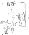
- FIG. 2 depicts another view of the EMN system 10, including a fluoroscopic imaging device 201 capable of acquiring fluoroscopic or x-ray images or video of the patient "P."
- the images, series of images, or video captured may be stored within the imaging device 302 or transmitted to workstation 80 for storage, processing, and display. Additionally, the imaging device 302 may rotate about the patient "P" so that images may be acquired from different angles or perspectives relative to the patient "P.”
- Imaging device 202 may include a single imaging device or more than one imaging device. In embodiments including multiple imaging devices, each imaging device may be a different type of imaging device or the same type. Further details regarding the imaging device 202 are described in U.S. Patent No. 8,565,858 .
- FIG. 3 there is shown a schematic view of fluoroscopic markers 301 positioned near a treatment target 303 within a bronchus of the patient.
- FIG. 3 further shows EWC 96 within the trachea of the patient with a guide wire 305 within EWC 96 and extending into a distally beyond distal tip 93 of the EWC 96 into a branch of the bronchial tree.
- Marker 301 is guided through EWC 96 using guide wire 305 to a location near treatment target 303.
- guide wire 305 reaches a position near target 303, appropriately distanced from other fluoroscopic markers 301, guide wire 305 releases fluoroscopic marker 305.
- Fluoroscopic markers 301 are distributed as equally as possible about the target to allow for a complete analysis of lung movement near treatment target 303. As will be appreciated, other mechanisms, systems, and methods for deploying fluoroscopic markers can be used without departing from the scope of the present disclosure.
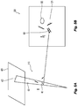
- FIG. 4 a three-dimensional diagram view of a process of locating a fluoroscopic marker between two fluoroscopic images is shown.
- FIG. 4 includes a first fluoroscopic first 407, a second fluoroscopic view 409, an angle 405 between fluoroscopic views 407, 409, and a 3D translation 403 between fluoroscopic views 407, 409.
- Fluoroscopic views 407, 409 are projected in 3D space and transposed relative to one another according to known angle 405 and initially according to assumed reasonable values for image diameter, pixel-to-mm ratio and source-to-image-distance.
- the orientation of fluoroscopic views 407, 409 is adapted over time according to pose estimation and other manipulations.
- First fluoroscopic view 407 includes a first fluoroscopic image 410, a first fluoroscopic 2D marker location 412 in first fluoroscopic image 410, a first fluoroscopic projection 414 of first fluoroscopic 2D marker location 41, and a first fluoroscopic imager 416.
- Second fluoroscopic view 407 includes a second fluoroscopic image 420, a second fluoroscopic 2D marker location 422 in second fluoroscopic image 420, a second fluoroscopic projection 424 of fluoroscopic marker 422 in second fluoroscopic image 420, and a second fluoroscopic imager 426.
- Fluoroscopic projections 414, 424 project from fluoroscopic imagers 416, 426 to end points of fluoroscopic 2D marker locations 412, 422.
- Fluoroscopic 2D marker locations 412, 422 represent angular 2D projections of fluoroscopic marker 301. Where fluoroscopic projections 414, 424 intersect, there is shown a 3D fluoroscopic marker position 401.
- 3D fluoroscopic marker position 401 represents an estimate of the 3D location of fluoroscopic marker 301.
- 3D fluoroscopic marker position 401 depends on known angle 405 and adjustable 3D translation 403. Fluoroscopic views 407, 409 may be adjusted in order to modify the size and location of 3D fluoroscopic marker position 401. In turn, comparing the accuracy of 3D fluoroscopic marker position's 401 size and shape informs the accuracy of 3D translation 403 between fluoroscopic views 407, 409.
- fluoroscopic imagers 416, 426 may be understood to refer to two locations of a single fluoroscopic imager.
- FIGS. 5A and 5B a two-dimensional diagram view showing translating of fluoroscopic marker data to CT images in order to compare and register the marker data is shown.
- FIGS. 5A and 5B show fluoroscopic frame 510 and CT frame 530 (respectively).
- Fluoroscopic frame 510 includes 3D fluoroscopic marker positions 401, generated according to 2D marker locations 422 in second fluoroscopic image 420 and first fluoroscopic 2D marker location 412 in first fluoroscopic image 410 (not shown in FIGS. 5A and 5B ).
- CT frame 530 represents a 2D view of a 3D image generated by performing a CT scan.
- CT frame 530 includes target 303, which may be originally identified in the 3D CT scan image, and CT marker locations 531 representing locations of fluoroscopic markers 301 according to the location of fluoroscopic markers 301 when the CT scan is performed.
- CT frame 530 also includes a translated version of 3D fluoroscopic marker positions 401.
- 3D fluoroscopic marker positions 401 are translated into CT frame 530 using a method, describe in detail below, known as pose estimation.
- registration of CT marker locations 531 according to the translated 3D fluoroscopic marker positions 401 may be performed and CT marker locations 531 may be updated. After all are updated, the new locations may be used to update a model of the bronchial tree to provide real time feedback to a physician performing a procedure. Additionally, target error may be determined according to the translation distance of CT marker locations 531 during registration and position update.
- a treatment target is identified.
- a target may be determined using pre-procedure CT images, MRI images, PET images, fluoroscopic images, or any other suitable imaging to determine a location of potentially problematic tissue within a patient.
- a physician may also navigate a sensor with a camera through the body and determine a treatment target through visual inspection of tissue.
- a path through the branches of the airways to the target is generated in CT or other image data.
- the pathway plan can be utilized in a navigation procedure using the EMN system 10.
- the pathway plan is loaded into an application on workstation 80 and displayed, allowing a physician LG 92 extending distally from bronchoscope 50 to a location near a treatment or biopsy target navigate bronchoscope 50 near a treatment target.
- application 81 may perform registration of the CT scan with the patient's airways, as described above, and in particular as described in copending U.S. Patent Application No. 14/790,581 , entitled REAL TIME AUTOMATIC REGISTRATION FEEDBACK, filed on July 2, 2015, by Brown et al..
- the location of EM sensor 94 within the patient's airways is tracked, and a plurality of points denoting the location of EM sensor 94 within the EM field generated by EM generator 76 is generated.
- the application 81 compares the locations of these points to the 3D model and seeks to fit all the points within the lumens of the 3D model.
- the patient and the 3D model are registered to one another.
- detected movement of the EM sensor 94 within the patient can be accurately depicted on the display of the workstation 80 as a sensor 94 traversing the 3D model or a 2D image from which the 3D model was generated.
- fluoroscopic marker 303 is decoupled from guide wire 305 and lodges within the lungs.
- Fluoroscopic marker 303 may include a bonding agent or gripping ridges to bind fluoroscopic marker 303 to a wall of the luminal network.
- Fluoroscopic marker 303 may also have a shape designed to securely lodge fluoroscopic marker 303 in a lung branch. Fluoroscopic markers 303 are placed at several locations near the treatment target with a distribution sufficient to allow for an estimation of movement of a moveable area surrounding the treatment target.
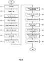
- the patient undergoes another CT scan, at step S607
- the scan concentrates on an area of interest of the patient, containing the treatment target and consequentially, fluoroscopic markers 303 which are usually near the treatment target.
- the treatment target and fluoroscopic markers 303 are detected and can be shown on displayed on monitoring equipment 60.
- 3D image data of the area of interest, the treatment target, and fluoroscopic markers 303 is generated and saved on a memory of computing device 80 or a network.
- preparation for fluoroscopic imaging begins.
- a contrasting agent possibly a contrast dye or iodine, is applied to the treatment target.
- the contrast agent creates a higher contrast for more detailed fluoroscopic imaging of tissue and allows a physician to view lung structure and features.
- FIG. 4 depicts steps S613 and S615 occurring sequential with step S615 following step S613.
- fluoroscopic images generated in step S613 and S615 are compared according to the known pose angle and distance between the poses of fluoroscopic imaging device 201.
- application 81 may generate a 3D space. Then, the images generated in steps S613 and S615 are projected through the 3D space from fluoroscopic imaging device 201.
- Application 81 may produce 3D fluoroscopic image data representing the projections of the images of the fluoroscopic imaging devices 201.
- application 81 may determine the aberration represents a 3D image point of the imaged lungs.
- Application 81 may further compare pixel densities across the entirety of the intersection volume of the image projections to generate estimated 3D image data, with the estimation being anchored according to positions of identified pixel aberrations.
- 3D image data may further be generated by comparing the image projections to the CT scan or a general model of the lungs.
- the locations of the markers are determined in 3D space from the fluoroscopic images.
- Fluoroscopic markers 303 appear in the fluoroscopic images as lines of high brightness pixels. Therefore, a fluoroscopic marker 303 is easily identifiable in a fluoroscopic image.
- Application 81 locates lines of high brightness pixels and identified 2D locations of each fluoroscopic marker 303. Using the known poses and locations of fluoroscopic imaging device 201 and identified positions of fluoroscopic markers 303 in the 2D fluoroscopic images, application 81 determines 3D coordinates for fluoroscopic markers 303 using a process that is described further in FIG. 5 .
- 3D locations of fluoroscopic markers 303 are determined in CT images generated at step S609. Determining locations of fluoroscopic markers in a 3D CT model can be accomplished using known methods. Generally, application 81 will identify a line of high brightness pixels and determine that the pixel line represents a fluoroscopic marker.
- the locations of fluoroscopic markers 303 determined, at step S619, using the fluoroscopic images and the locations of fluoroscopic markers 303 determined at step S621, using the CT images are compared.
- Marker locations may be compared as a group according to a center of each set of markers location. Individual marker locations may also be compared.
- application 81 determines corresponding marker locations for comparison according to which markers locations have substantially similar 3D coordinates. Once corresponding marker locations have been determined, Application 81 measures the distance between corresponding fluoroscopic image marker locations and the CT image marker locations. The distance between marker locations is determined to be movement of fluoroscopic markers 303 between the time the CT scan was performed and the fluoroscopic imaging was performed.
- step S625 application 81 determines the distances between markers in the fluoroscopic 3D image data and CT 3D image data. If the distance exceeds a predetermined amount or ratio, the marker is excluded from modification of 3D CT image data. Additionally, markers that are not excluded may be weighted according to their distance from the target. Weighing may be established according to a general equation based on the distance from the target or a physician may determine how to weight the markers.
- step S627 application 81 modifies the 3D CT image data according to the locations of the markers in the 3D image data. Markers excluded at step S625 are not used to update and modify the 3D CT image data. Application 81 may modify the 3D CT image data according to weights established in step S625. The modified 3D CT image data is then used to update the 3D model of the luminal network.
- the updated 3D model and/or CT image data including updated marker locations is displayed.
- the displayed 3D model and/or CT image data may be used to update or plan a path to navigate to the treatment target.
- the displayed 3D model and/or CT image data may also provide guidance while a physician is navigating a tool to a treatment target.
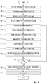
- FIG. 7 there is shown a flow chart of a method of locating 3D marker locations in an intersection of fluoroscopic images projections and updating a CT model of a luminal network according to marker locations in the fluoroscopic images.
- the process begins at step S701.
- application 81 generates first 3D space and axes for establishing a coordinate system to define the 3D space for a first fluoroscopic view.
- relative positions for 2D first fluoroscopic image 410 and first fluoroscopic imager 416 which generates first fluoroscopic image 410 are established.
- the position and size of 2D first fluoroscopic image 410 and the position of first fluoroscopic imager 416 in the 3D space is set according to initial, assumed reasonable values for image diameter, pixel-to-mm ratio and source-to-image-distance.
- Image diameter establishes the size of first fluoroscopic image 410 in the 3D space;
- pixel-to-mm ratio establishes brightness density according to the distance and image diameter;
- source-to-image-distance establishes a distance between first fluoroscopic image 410 and first fluoroscopic imager 416.
- the axes' origin may be determined arbitrarily, though in practice, the origin may conveniently be placed approximate a midpoint of first fluoroscopic image 410 and first fluoroscopic imager 416.
- application 81 determines a relative 3D positioning between 2D second fluoroscopic image 420 and fluoroscopic imager 426 and determines a size of fluoroscopic image 420 according to initial, assumed reasonable values for image diameter, pixel to mm ratio and source-to-image-distance.
- the assumed values may, but need not, be the same or approximately the same as the assumed reasonable values in step S701.
- application 81 identifies fluoroscopic 2D marker location 412, 422 of fluoroscopic markers 301 within first fluoroscopic image 410 and second fluoroscopic image 420.
- Application 81 scans fluoroscopic images 410, 420 searching for bright portions of the image having a shape the same as or similar to a shape as the fluoroscopic markers 301, these are shown in Fig. 5 as a rod or line.
- the bright portions may be determined by scanning pixel values of image data of fluoroscopic images 410, 420 and locating a grouping of high brightness pixels.
- image processing software known in the art may be used so measure a bright portion of fluoroscopic images 410, 420 and determine a shape of the bright portion.
- application 81 assigns 3D coordinates to the end points according to the location of the end points within the coordinate system. The 3D end point coordinates may therefore be used to define locations of fluoroscopic 2D marker locations 412, 422 on fluoroscopic images 410, 420 within the 3D space.
- each first fluoroscopic 2D marker location 412 and each second fluoroscopic 2D marker location 422 is established according to the angle 405.
- Each pair of corresponding marker locations represents projections of a single fluoroscopic marker 301.
- application 81 may perform a pose estimation procedure according to CT marker location 531.
- a pose estimation procedure includes determining fluoroscope projection angles, focal point, and zoom relative to the 3D CT model generally includes extracting CT data and overlaying it on the fluoroscopic image. The process of determining fluoroscope projection angles, focal point, and zoom is more fully described in commonly-owned U.S. Patent Application Serial No. 14/725,300 , ( US 2016-0005168 A1 ) entitled "Fluoroscopic Pose Estimation,” filed on May 29, 2015, by Merlet.
- 3D translation 403 has not yet been established. Establishment of 3D translation 403 between the fluoroscope views is necessary to align fluoroscopic projection 414, 424 to determine 3D fluoroscopic marker positions 401 in 3D space.
- application 81 generates an initial estimate of 3D translation 403.
- Application 81 determines the center of mass for first fluoroscopic 2D marker locations 412 and a center of mass for second fluoroscopic 2D marker location 422. In order to find the centers of mass, each marker is weighted equally and the x, y, and z coordinates along the lengths of the fluoroscopic 2D marker locations 412, 422 are averaged.
- the end points of fluoroscopic 2D marker locations 412, 422 may be used.
- application 81 translates the fluoroscopic views in the 3D space such that a projection ray between first fluoroscopic imager 416 and the center of mass of first fluoroscopic 2D marker locations 412 intersects a projection ray between second fluoroscopic imager 416 and the center of mass of second fluoroscopic 2D marker location 422.
- Application 81 further translates the fluoroscopic views in the 3D space so that the distances between the intersection of the projected rays and each fluoroscopic imager 416, 426 are substantially equal.
- Application 81 may perform pose estimation to develop the initial estimate of 3D translation 403. Pose estimation is performed for each fluoroscopic view. The pose estimate matches CT marker location 531 with fluoroscopic 2D marker locations 412, 422 and translates, as the initial estimate, the fluoroscopic views according to the result of the pose estimation.
- 3D translation 403 is revised.
- 3D translation 403 can be described by lengths (Tx, Ty, Tz). Revision to 3D translation 403 may come in a variety of forms.
- application 81 adjusts Tx, Ty, Tz values individually by a small amount, though an combination of Tx, Ty, Tz values may be adjusted.
- application 81 generates first fluoroscopic projection 414 and second fluoroscopic projection 424 for each pair of corresponding marker locations and determines 3D fluoroscopic marker position 401 for each pair.
- 3D fluoroscopic marker positions 401 are determined for all fluoroscopic markers 301, the process proceeds to steps S711-S719 to determine the accuracy of 3D translation 403.
- application 81 develops mutual distances between marker locations in CT images from fluoroscopic frame 530 by measuring distances between each CT marker location 531 and every other CT marker location 531 and between each 3D fluoroscopic marker position 401 and every other 3D fluoroscopic marker position 401. For purposes of simplifying the calculation, application 81 may determine a center point for each CT marker location 531 and each 3D fluoroscopic marker position 401, thereby allowing distances between marker locations within a single imaging frame, fluoroscopic frame 510 or fluoroscopic frame 530, to be determined by subtracting x, y, and z coordinates of marker location center points. At step S715, the mutual distances between markers are compared across imaging frames.
- step S717 application 81 determines coordinates of endpoints of 3D fluoroscopic marker positions 401. For each 3D fluoroscopic marker position 401, application 81 subtracts the x, y, z, coordinates of the endpoints to determine the lengths of 3D fluoroscopic marker positions 401. The lengths are then compared against a known length of fluoroscopic markers 301 to determine an accuracy of 3D fluoroscopic marker positions 401.
- step S719 application 81 determines distances between first fluoroscopic imager 416 and each end point of first fluoroscopic 2D marker locations 412 and distances between second fluoroscopic imager 426 and each end point of second fluoroscopic 2D marker locations 422. Then, application 81 compares the determined distances associated with opposing end points of each pair of corresponding marker locations.
- step S721 application 81 registers the results from the comparisons of mutual distances, marker length, and distances between rays to a common end point. Using these comparisons, application 81 develops a numerical score.
- the numerical score may be determined according to a cumulative calculation wherein each comparison receives an individual score and the individual scores are summed. Individual comparison scores may additionally be weighted prior to calculating a summed score. Alternatively, the numerical score may be determined based on each comparison considered simultaneously, the result of each comparison informing and determining an impact of each of the other comparisons. Once a score is determined, at step S723, application 81 or a user determines whether the numerical score is acceptable.
- Determining acceptability of the numerical score may, for example, include comparing the score against predetermined threshold value, with or without an error factor. As an additional example, determining acceptability may include presenting the user with the score to allow the user to determine whether the score is acceptable. As a final but not conclusive example, the acceptability of the score may be determined according to previously determined scores. As the process iterates through steps S709-S721, application 81 determines a score for each revision of the 3D translations. This process allows for a sweeping of 3D translation values to determine 3D translation values at which the numerical score is at or near its lowest possible value. To accomplish such a sweep, application 81 may determine if a sufficient number of iterations have been performed or if progressive scores have ceased to improve substantially.
- application 81 may determine that the score is acceptable.
- step S725 application 81 performs registration of 3D fluoroscopic marker locations 401 from fluoroscopic images 410 to CT marker locations 531 to correct CT marker locations 531 so that CT marker locations 531 accurately reflect the true, up-to-date positions of fluoroscopic markers 301.
- application 81 performs a pose estimation procedure as described in previously reference and Application Serial No. 14/725,300 .
- the pose estimation procedure solves for a rotation angle and translation coordinates in order to overlay 3D fluoroscopic marker locations 401 within CT frame 530.
- 3D fluoroscopic marker locations 401 and CT marker locations 531 are both translated into and displayed in CT frame 530, CT marker locations are modified according to the translated 3D fluoroscopic marker locations 401.
- Registration of 3D fluoroscopic marker locations 401 to CT marker locations 531 may be performed in a variety of manners. For example, all 3D fluoroscopic marker locations 401 may be given equal weight. Accordingly, CT marker locations 531 may be relocated to corresponding positions of 3D fluoroscopic marker locations 401. Additionally, instead of moving CT marker locations 531 to the exact locations of 3D fluoroscopic marker locations 401, a center of gravity of 3D fluoroscopic marker locations 401 and of CT marker locations 531 may be determined and CT marker locations 531 may be shifted such that their center of gravity becomes the same as the center of gravity of 3D fluoroscopic marker locations 401. As another alternative, the center of gravity of CT marker locations 531 may shift toward the center of gravity of 3D fluoroscopic marker locations 401, but stop short of fully relocating to the position.
- the registration may also apply unequal weight to 3D fluoroscopic marker locations 401.
- application 81 may determine distances between 3D fluoroscopic marker locations 401 and corresponding CT marker locations 531. If a distance for one or more corresponding markers is greater than a certain threshold or percentage value, application 81 may determine that that particular marker may have dislodged and migrated. Registration using a marker that has migrated would disturb the updated positions and create an inaccurate result. Therefore, if a distance for one or more corresponding markers is greater than a certain threshold or percentage value, the specific 3D fluoroscopic marker locations 401 may be excluded. Then, registration is performed as usual according to previously discussed methods or methods commonly known in the art.
- the registration may also apply varied weights to 3D fluoroscopic marker locations 401 without excluding any 3D fluoroscopic marker locations 401.
- 3D fluoroscopic marker locations 401 may be assigned a weight according to their proximity to target 303. Weighting of 3D fluoroscopic marker locations 401 may generate a better registration at target 303 as fluoroscopic markers 301 will tend to move in closer relation to the movement of target 303. After weighting, registration is performed as usual according to previously discussed methods or methods commonly known in the art.
- the new CT marker locations may then be used to update a previously developed model of the lungs. Updates to the model may occur in real time as the patient is imaged using fluoroscopic imaging. Continual updates to the model provide increased accuracy to the model and aid a physician's ability to accurately track treatment target 303 while performing a surgical procedure at target 303.
- step S727 application 81 determines a target error based on a comparison of CT marker locations 531 before and after the registrationCertain CT marker locations 531 may be excluded from the calculation of target error if a distance between a specific CT marker location 531 before and after the registration is large so as to indicate that the specific CT marker location 531 has migrated.
- the shift distance by CT marker locations 531 before and after the registration is compared against the 3D location of the original CT position with respect to target 303.
- FIG. 8 there is shown a graph presenting exemplary data of true target error in 3D as a function of the estimated target error for four fluoroscopic markers.
- the graph shows that as the estimated 3D target error decreases, the variance in median 3D target error also decreases. Therefore, when the estimated 3D target error is low, a physician performing the processes of the current application may more closely rely on the results of the procedure. If a physician is not satisfied with the potential median 3D target error for a given estimated 3D target error, the physician may choose to re-perform the procedure. Such a determination may depend on conditions such as size of the treatment target, length of time for performing treatment on the target, type of tissue and a number of other similar considerations.
- Workstation 80 may include memory 902, processor 904, display 906, network interface 908, input device 910, and/or output module 912.
- Memory 902 includes any non-transitory computer-readable storage media for storing data and/or software that is executable by processor 904 and which controls the operation of workstation 80.
- memory 902 may include one or more solid-state storage devices such as flash memory chips.
- memory 902 may include one or more mass storage devices connected to the processor 904 through a mass storage controller (not shown) and a communications bus (not shown).
- mass storage controller not shown
- communications bus not shown
- computer readable storage media includes non-transitory, volatile and non-volatile, removable and non-removable media implemented in any method or technology for storage of information such as computer-readable instructions, data structures, program modules or other data.
- computer-readable storage media includes RAM, ROM, EPROM, EEPROM, flash memory or other solid state memory technology, CD-ROM, DVD, Blu-Ray or other optical storage, magnetic cassettes, magnetic tape, magnetic disk storage or other magnetic storage devices, or any other medium which can be used to store the desired information and which can be accessed by workstation 80.
- Memory 902 may store application 81 and/or CT data 214.
- Application 81 may, when executed by processor 904, cause display 906 to present user interface 916.
- Network interface 908 may be configured to connect to a network such as a local area network (LAN) consisting of a wired network and/or a wireless network, a wide area network (WAN), a wireless mobile network, a Bluetooth network, and/or the internet.
- Input device 910 may be any device by means of which a clinician may interact with workstation 80, such as, for example, a mouse, keyboard, foot pedal, touch screen, and/or voice interface.
- Output module 912 may include any connectivity port or bus, such as, for example, parallel ports, serial ports, universal serial busses (USB), or any other similar connectivity port known to those skilled in the art.
Description
- The present disclosure relates to bronchial registration and, more particularly, to devices, systems, and methods for updating a three-dimensional bronchial tree model with fluoroscopic projections.
- Standard of care for lung diseases, such as asthma, chronic obstructive pulmonary disease (COPD), and chronic obstructive lung disease (COLD), and other lung-related diseases has been focused largely on medical procedures such as resection and lobectomies which are highly invasive to patients. And while medicinal therapies have been developed these tend to focus on cancer treatments such as chemotherapy drugs.
- Electromagnetic navigation (EMN) has helped expand the possibilities of treatment of luminal networks such as the lungs. EMN relies on non-invasive imaging technologies, such as computed tomography (CT) scanning and magnetic resonance imaging (MRI) to generate 3-dimensional models of a luminal network. EMN in combination with these non-invasive imaging technologies has been also used to identify a location of a target and to help clinicians navigate a luminal network of the lung to the target. CT and MRI procedures come with certain drawbacks. CT imaging cannot be used in real time due to a long reconstruction time and the radiation hazard to the physicians. MRI similarly cannot be used in real time as the MRI housing restricts space to perform a procedure and metallic items cannot be used around and MRI.
- As an alternative to CT and MRI, fluoroscopic imaging may be used to provide real-time imaging capabilities. However, fluoroscopic images, while useful, present certain drawbacks for navigation. Using fluoroscopic imaging, it is often difficult to distinguish luminal passageways from solid tissue. Moreover, images generated by the fluoroscope are two-dimensional whereas navigating the airways of a patient requires the ability to maneuver in three dimensions.
- Therefore, there is a need for an imaging process and system that combines CT or MRI imaging with fluoroscopic imaging to provide a 3D rendering of a patient's luminal network with the requisite resolution while also updating the 3D model in real time using imaging modalities the can only produce 2D image data.
- Document
US2007276243 A1 may be considered to disclose a system comprising: a display configured to display: 3D image data of a target area, first 2D image data of the target imaged from a first viewpoint, and second 2D image data of the target imaged from a second viewpoint, the second viewpoint oriented at a known angle from the first viewpoint; a computing device including a processor and a memory storing instructions which, when executed by the processor, cause the computing device to: determine locations of the fiducial markers in 3D space according to locations of the fiducial markers within first 2D image data, second 2D image data, and the known angle; and update the 3D image data with the determined locations of the of an instrument in 3D space. - Provided in accordance with the present disclosure is a method of updating a model of a luminal network. The method includes performing first imaging of a target, generating 3D image data including locations of fiducial markers using images captured in the first imaging, performing second imaging of the target from a first viewpoint and a second viewpoint, generating 2D image data including locations of the fiducial markers from the first viewpoint and the second viewpoint using images captured in the second imaging, determining locations of the fiducial markers in 3D space according to locations of the fiducial markers within the 2D image data of the first viewpoint, locations of the fiducial markers within the 2D image data of the second viewpoint, and the known angle, and registering the 3D image data generated using images captured in the first imaging with the determined locations of the fiducial markers in 3D space. The first viewpoint and the second viewpoint are oriented at a known angle relative to each other.
- In an aspect of the present disclosure, the first imaging is performed using CT imaging.
- In another aspect of the present disclosure, the second imaging is performed using fluoroscopic imaging.
- In yet another aspect of the present disclosure, determining locations of the fiducial markers in 3D space includes projecting rays from the first viewpoint through endpoints of each fiducial marker, projecting rays from the second viewpoint through the endpoints of each fiducial marker, determining intersections of the rays projected from the first source and the rays projected from the second source as locations of fiducial marker endpoints in 3D space.
- In a further aspect of the present disclosure, the method further includes determining a distance between adjacent fiducial marker endpoints and comparing the distance between adjacent fiducial marker endpoints with a known length of the fiducial marker.
- In an aspect of the present disclosure, the method further includes determining movement distances between fiducial marker locations in 3D space and fiducial marker locations in the 3D image data from the first imaging.
- In a further aspect of the present disclosure, updating the 3D image data includes determining which movement distance is greatest and registering the 3D image data generated using images captured in the first imaging with the determined locations of the fiducial markers in 3D space without the location in 3D space of the fiducial marker corresponding to the greatest movement distance.
- In another aspect of the present disclosure, updating the 3D image data includes determining a distance of each fiducial marker from the treatment target, weighting each fiducial marker according to its distance from the treatment target, and registering the 3D image data generated using images captured in the first imaging with the determined locations of the fiducial markers in 3D space according to the weight of each fiducial marker.
- In another aspect of the present disclosure, the method further includes determining a distance of each fiducial marker from the treatment target, weighting each fiducial marker according to its distance from the treatment target, and registering the 3D image data generated using images captured in the first imaging with the determined locations of the fiducial markers in 3D space according to the weight of each fiducial marker.
- In another aspect of the present disclosure, the method further includes measuring changes in location of fiducial markers in the 3D image data generated using images captured in the first imaging before and after registration, and determining a target error base on changes in location of fiducial markers in the 3D image data.
- In a further aspect of the present disclosure, the method further includes excluding, from the determination of target error, changes in location of fiducial markers in the 3D where the change in the location of the fiducial marker exceeds a threshold value.
- Provided in accordance with the present disclosure is a system including a display and a computing device including a processor and a memory. The display is configured to display 3D image data of a target area, first 2D image data of the target imaged from a first viewpoint, and second 2D image data of the target imaged from a second viewpoint. The 3D image data includes locations of fiducial markers. The second viewpoint oriented at a known angle from the first viewpoint. The memory stores instruction which, when executed by the processor, cause the computing device to determine locations of the fiducial markers in 3D space according to locations of the fiducial markers within first 2D image data, second 2D image data, and the known angle, and update the 3D image data with the determined locations of the fiducial markers in 3D space.
- In an aspect of the present disclosure, the 3D image data is generate using CT imaging.
- In another aspect of the present disclosure the first and second 2D image data are generate using fluoroscopic imaging.
- In another aspect of the present disclosure, in the determination of locations of the fiducial markers in 3D space, the instructions further cause the computing device to project rays from the first viewpoint through endpoints of each fiducial marker, project rays from the second viewpoint through the endpoints of each fiducial marker, and determine intersections of the rays projected from the first source and the rays projected from the second source as locations of fiducial marker endpoints in 3D space.
- In another aspect of the present disclosure, the instructions further cause the computing device to determine a distance between adjacent fiducial marker endpoints, and compare the distance between adjacent fiducial marker endpoints with a known length of the fiducial marker.
- In yet another aspect of the present disclosure, the instructions further cause the computing device to determine movement distances between fiducial marker locations in 3D space and fiducial marker locations in the 3D image data.
- In a further aspect of the present disclosure, the instructions further cause the computing device to determine which movement distance is greatest and register the 3D image data with the determined locations of the fiducial markers in 3D space without the location in 3D space of the fiducial marker corresponding to the greatest movement distance.
- In a further aspect of the present disclosure, the instructions further cause the computing device to determine a distance of each fiducial marker from the treatment target, weight each fiducial marker according to its distance from the treatment target, and register the 3D image data with the determined locations of the fiducial markers in 3D space according to the weight of each fiducial marker.
- In another aspect of the present disclosure, the instructions further cause the computing device to measure changes in location of fiducial markers in the 3D image data generated using images captured in the first imaging before and after registration, and determine a target error base on changes in location of fiducial markers in the 3D image data.
- In another aspect of the present disclosure, the instructions further cause the computing device to exclude, from the determination of target error, changes in location of fiducial markers in the 3D where the change in the location of the fiducial marker exceeds a threshold value.
- Any of the above aspects and embodiments of the present disclosure may be combined without departing from the scope of the present disclosure.
- Various aspects and features of the present disclosure are described hereinbelow with references to the drawings, wherein:
-
FIG. 1 is a perspective view of an electromagnetic navigation system in accordance with the present disclosure; -
FIG. 2 is an end view of a fluoroscopic imaging C-arm incorporated in the EMN system ofFIG. 1 ; -
FIG. 3 is a schematic view of fluoroscopic markers positioned near a treatment target within a bronchus of the patient; -
FIG. 4 is three-dimensional diagram view of a process of locating a fluoroscopic marker between two fluoroscopic images; -
FIG. 5 is two-dimensional diagram view showing translating of fluoroscopic marker data to CT images order to compare and register the marker data; -
FIG. 6 is a flow chart of a method of placing the fluoroscopic markers ofFig. 3 and updating a CT model of a luminal network; -
FIG. 7 is a flow chart of a method of locating 3D marker locations in an intersection of fluoroscopic images projections and updating a CT model of a luminal network according to marker locations in the fluoroscopic images; -
FIG. 8 is a graph presenting exemplary data of true target error in 3D as a function of the estimated target error; and -
FIG. 9 is a schematic block diagram of a workstation configured for use with the system ofFIG. 1 . - The present disclosure is directed to devices, systems, and methods for generating and updating a three dimensional model of a luminal network. More particularly, the disclosure relates to modifying a three-dimensional model of a patient's lungs using two or more two-dimensional images by capturing and comparing common features or indicators observable in both the three-dimensional model and the two-dimensional images.
- A physician may perform a CT scan of a patient's airways to generate a three-dimensional model to aid the clinician in navigating the lungs. A patient's lungs, however, are not static. The lungs move during a typical respiration cycle in a normative pattern. Over time, the positions of various elements of the lungs migrate and change position, compromising the accuracy of the CT scan. While the CT scan may provide a model of the lungs accurate enough to allow a physician to navigate near a treatment target, a higher degree of accuracy is necessary to navigate to a treatment target near outermost positions of the bronchial tree and to remain at the treatment target throughout the intended treatment procedure.
- In order to increase the accuracy of the three-dimensional model, a physician may guide a bronchoscopic navigation catheter near the treatment target to place fiducial markers that are observable using CT imaging and fluoroscopic imaging. In accordance with one embodiment of the present disclosure, after performing a CT scan on the patient's airways, 3D data and a 3D model including fiducial marker locations are generated. During, or just prior to, a procedure, the airways, including the fiducial markers placed within, are imaged again using fluoroscopic imaging from at least two orientations. By selectively comparing locations of the fiducial markers in the 3D data and model with locations of the fiducial markers within the fluoroscopic images, the 3D model maybe be updated immediately preceding or in real time during the procedure.
- The updated 3D model may be useful for performing an electromagnetic navigation (EMN). An EMN generally involves at least two phases: (1) planning a pathway to a target located within, or adjacent to, the patient's lungs; and (2) navigating a probe to the target along the planned pathway. These phases are generally referred to as (1) "planning" and (2) "navigation."
- Prior to the planning phase, the patient's lungs are imaged by, for example, a computed tomography (CT) scan, although additional applicable methods of imaging will be known to those skilled in the art. The image data assembled during the CT scan may then be stored in, for example, the Digital Imaging and Communications in Medicine (DICOM) format, although additional applicable formats will be known to those skilled in the art. The CT scan image data may then be loaded into a planning software application ("application") to be used during the planning phase of the EMN.
- With reference to
FIG. 1 , anEMN system 10 suitable for implementing methods for planning and performing treatment of an area of a patient's lungs and placing fiducial markers is provided in accordance with the present disclosure. Onesuch EMN system 10 is the ELECTROMAGNETIC NAVIGATION BRONCHOSCOPY® system currently sold by Covidien LP. As shown inFIG. 1 ,EMN system 10 is used to perform one or more procedures on a patient supported on an operating table 40. In this regard,EMN system 10 generally includes abronchoscope 50,monitoring equipment 60, an electromagnetic (EM) trackingsystem 70, and acomputing device 80. -
Bronchoscope 50 is configured for insertion through the patient's mouth and/or nose into the patient's airways. As illustrated inFIG. 1 , the patient is shown lying on operating table 40 withbronchoscope 50 inserted through the patient's mouth and into the patient's airways.Bronchoscope 50 includes a source of illumination and a video imaging system (not explicitly shown) and is coupled tomonitoring equipment 60, for example, a video display, for displaying the video images received from the video imaging system ofbronchoscope 50. - In an embodiment,
bronchoscope 50 may operate in conjunction with a catheter guide assembly, two types of which are depicted inFIG. 1 (for example,catheter guide assemblies 90, 100).Catheter guide assemblies LG 92 andEWC 96 are configured for insertion through a working channel ofbronchoscope 50 into the patient's airways (although thecatheter guide assemblies catheter guide assemblies catheter guide assembly handle 91, which is connected to an extended working channel (EWC) 96. In eachassembly EWC 96 is sized for placement into the working channel ofbronchoscope 50. In the operation of eachassembly EM sensor 94, is inserted intoEWC 96 and locked into position such thatEM sensor 94 extends a desired distance beyond thedistal tip 93 ofEWC 96. The location ofEM sensor 94, and thus the distal end ofEWC 96, within an EM field generated byEM field generator 76 can be derived by trackingmodule 72, andcomputing device 80.Catheter guide assemblies distal tip 93 ofLG 92 andEWC 96. -
Catheter guide assembly 90 is currently marketed and sold by Covidien LP under the name SUPERDIMENSION® Procedure Kits.Catheter guide assembly 100 is currently sold by Covidien LP under the name EDGETM Procedure Kits. Both kits includehandle 91,EWC 96, andLG 92. For a more detailed description ofcatheter guide assemblies U.S. Patent Publication No. 2014/0046315 , entitled "MICROWAVE ABLATION CATHETER AND METHOD OF UTILIZING THE SAME", filed on March 15, 2013 by Ladtkow et al.. -
LG 92 andEWC 96 are selectively lockable relative to one another via alocking mechanism 99. A six degrees-of-freedomEM tracking system 70, e.g., similar to those disclosed inU.S. Patent No. 6,188,355 and publishedPCT Application Nos. WO 00/10456 WO 01/67035 -
EM tracking system 70 may be configured for use withcatheter guide assemblies EM sensor 94 as it moves in conjunction withEWC 96 through the airways of the patient, as detailed below. In an embodiment,EM tracking system 70 includes atracking module 72, a plurality ofreference sensors 74, and anEM field generator 76. As shown inFIG. 1 ,EM field generator 76 is positioned beneath the patient.EM field generator 76 and the plurality ofreference sensors 74 are interconnected withtracking module 72, which derives the location of eachreference sensor 74 in the six degrees of freedom. One or more ofreference sensors 74 are attached to the chest of the patient. The six degrees of freedom coordinates ofreference sensors 74 are sent as data tocomputing device 80, which includesapplication 81, where the data fromsensors 74 are used to calculate a patient coordinate frame of reference. - According to an embodiment,
catheter guide assemblies LG 92. Surgical tools may be used to collect one or more tissue sample from the target location, apply energy to the target location, or perform similar functions. An embodiment, trackingsystem 70 may be configured in conjunction with a surgical tool to facilitate navigation of the tool to the target location, and tracking of a location of the tool as it is manipulated relative to the target location to obtain the tissue sample. - For example, a variety of useable tools are described in
U.S. Patent Publication No. 2015/0141809 , entitled "DEVICES, SYSTEMS, AND METHODS FOR NAVIGATING A BIOPSY TOOL TO A TARGET LOCATION AND OBTAINING A TISSUE SAMPLE USING THE SAME", filed September 17, 2014, by Costello et al., andU.S. Patent Publication No. 2015/0265257 , entitled "DEVICES, SYSTEMS, AND METHODS FOR NAVIGATING A BIOPSY TOOL TO A TARGET LOCATION AND OBTAINING A TISSUE SAMPLE USING THE SAME", filed December 9, 2014, by Costello et al., and useable with theEMN system 10 as described herein. -
Computing device 80 includes software and/or hardware, such as anEMN application 81, used to facilitate the various phases of an EMN procedure, including generating the 3D model, identification of a target location, planning a pathway to the target location, registration of the 3D model with the patient's actual airways, and navigation to the target location. For example, during procedure planning,computing device 80 utilizes computed tomographic (CT) scan, magnetic resonance imaging (MRI) scan, and/or positron emission tomography (PET) scan image data for generating and viewing the 3D model of the patient's airways, enables the identification of a target location on the 3D model (automatically, semi-automatically or manually), and allows for the determination and selection of a pathway through the patient's airways to the target location. While the CT scan image data may have gaps, omissions, and/or other imperfections included in the image data, the 3D model is a smooth representation of the patient's airways, with any such gaps, omissions, and/or imperfections in the CT scan image data filled in or corrected. The 3D model may be presented on a display monitor associated withcomputing device 80, or in any other suitable fashion. An example of the planning software described herein can be found inU.S. Patent Publication Nos. 2014/0281961 ,2014/0270441 , and2014/0282216, filed by Baker et al. on March 15, 2013 , and entitled "PATHWAY PLANNING SYSTEM AND METHOD". Further examples of the planning software can be found in commonly assignedU.S. Patent Application No. 14/753,288 , (US 2016-0000302 A1 ) entitled "SYSTEM AND METHOD FOR NAVIGATING WITHIN THE LUNG", filed on June 29, 2015, by Brown et al.. - Using
computing device 80, various views of the 3D model may be presented and may be manipulated by a clinician to facilitate identification of a target location and selection of a suitable pathway through the patient's airways to access the target location. As noted above, the target location may be a surgical site where the treatment is to be performed, and/or a portion of or entire lobe of the patient's lungs requiring treatment. The 3D model may include, among other things, a model airway tree corresponding to the actual airways of the patient's lungs, and showing the various passages, branches, and bifurcations of the patient's actual airway tree. Additionally, the 3D model may include lesions, markers, blood vessels and vascular structures, lymphatic vessels and structures, organs, other physiological structures, and/or a 3D rendering of the pleura and fissures of the lungs. Some or all of the aforementioned elements may be selectively displayed, such that the clinician may choose which elements should be displayed when viewing the 3D model. For example,EMN application 81 may be configured in various states to display the 3D model in a variety of view modes. For each view of the 3D model, the angle from which the 3D model is displayed may correspond to a view point. The view point may be fixed at a predefined location and/or orientation, or may be adjusted by the clinicianoperating computing device 80. -
Computing device 80, viaapplication 81, may further be configured to review the plan created by the clinician to determine if the plan accounts for all detected abnormalities in the lungs of the patient. For example, an abnormality may be detected where a lung fissure is determined to be partially incomplete or entirely absent. An abnormality may also be detected if airways, blood vessels, and/or lymphatic lumens from one lung lobe have fused with airways, blood vessels, or lymphatic lumens from another lung lobe, and thereby breached the division between the lung lobes. Ifcomputing device 80 determines that the plan created by the clinician does not account for all detected abnormalities, adjustments to the plan may be determined and presented to the clinician for review. - Following planning, a procedure may be undertaken in which
EM sensor 94, in conjunction with trackingsystem 70, enables tracking of EM sensor 94 (and thus the distal end ofEWC 96 or a surgical tool) asEM sensor 94 is advanced through the patient's airways following the pathway planned during the planning phase. As an initial step of the procedure, the 3D model is registered with the patient's actual airways. One potential method of registration involves navigatingLG 92 into each lobe of the patient's lungs to at least the second bifurcation of the airways of that lobe. The position ofLG 92 is tracked during this registration phase, and the 3D model is iteratively updated based on the tracked position of the locatable guide within the actual airways of the patient's lungs. This registration process is described in commonly-ownedU.S. Patent Application Publication No. 2011/0085720 , entitled "AUTOMATIC REGISTRATION TECHNIQUE," filed on May 14, 2010, by Barak et al., andU.S. Patent Application Serial No. 14/790,581 (US 2016-0000356 A1 ) entitled "REAL-TIME AUTOMATIC REGISTRATION FEEDBACK", filed on July 2, 2015, by Brown et al.. While the registration process focuses on aligning the patient's actual airways with the airways of the 3D model, registration also ensures that the position of vascular structures, pleura, and fissures of the lungs are accurately determined. -
FIG. 2 depicts another view of theEMN system 10, including afluoroscopic imaging device 201 capable of acquiring fluoroscopic or x-ray images or video of the patient "P." The images, series of images, or video captured may be stored within the imaging device 302 or transmitted toworkstation 80 for storage, processing, and display. Additionally, the imaging device 302 may rotate about the patient "P" so that images may be acquired from different angles or perspectives relative to the patient "P." Imaging device 202 may include a single imaging device or more than one imaging device. In embodiments including multiple imaging devices, each imaging device may be a different type of imaging device or the same type. Further details regarding the imaging device 202 are described inU.S. Patent No. 8,565,858 . - Turning to
FIG. 3 , there is shown a schematic view offluoroscopic markers 301 positioned near atreatment target 303 within a bronchus of the patient.FIG. 3 further showsEWC 96 within the trachea of the patient with aguide wire 305 withinEWC 96 and extending into a distally beyonddistal tip 93 of theEWC 96 into a branch of the bronchial tree.Marker 301 is guided throughEWC 96 usingguide wire 305 to a location neartreatment target 303. Whenguide wire 305 reaches a position neartarget 303, appropriately distanced from otherfluoroscopic markers 301,guide wire 305 releasesfluoroscopic marker 305.Fluoroscopic markers 301 are distributed as equally as possible about the target to allow for a complete analysis of lung movement neartreatment target 303. As will be appreciated, other mechanisms, systems, and methods for deploying fluoroscopic markers can be used without departing from the scope of the present disclosure. - Referring now to
FIG. 4 , a three-dimensional diagram view of a process of locating a fluoroscopic marker between two fluoroscopic images is shown.FIG. 4 includes a first fluoroscopic first 407, a secondfluoroscopic view 409, anangle 405 betweenfluoroscopic views 3D translation 403 betweenfluoroscopic views angle 405 and initially according to assumed reasonable values for image diameter, pixel-to-mm ratio and source-to-image-distance. The orientation offluoroscopic views - First
fluoroscopic view 407 includes a firstfluoroscopic image 410, a first fluoroscopic2D marker location 412 in firstfluoroscopic image 410, a firstfluoroscopic projection 414 of first fluoroscopic 2D marker location 41, and a firstfluoroscopic imager 416. Secondfluoroscopic view 407 includes a secondfluoroscopic image 420, a second fluoroscopic2D marker location 422 in secondfluoroscopic image 420, a secondfluoroscopic projection 424 offluoroscopic marker 422 in secondfluoroscopic image 420, and a secondfluoroscopic imager 426.Fluoroscopic projections fluoroscopic imagers 2D marker locations Fluoroscopic 2D marker locations fluoroscopic marker 301. Wherefluoroscopic projections fluoroscopic marker position 401. 3Dfluoroscopic marker position 401 represents an estimate of the 3D location offluoroscopic marker 301. 3Dfluoroscopic marker position 401 depends on knownangle 405 andadjustable 3D translation 403. Fluoroscopic views 407, 409 may be adjusted in order to modify the size and location of 3Dfluoroscopic marker position 401. In turn, comparing the accuracy of 3D fluoroscopic marker position's 401 size and shape informs the accuracy of3D translation 403 betweenfluoroscopic views fluoroscopic marker 301 located within the fluoroscopic imaging frame. Once 3D fluoroscopic marker positions 401 are determine for eachfluoroscopic marker 301 located within the fluoroscopic imaging frame, 3D fluoroscopic marker positions 401 may then be translated onto CT scans to compare marker locations from fluoroscopic imaging and CT imaging. - Though described herein as utilizing two separate
fluoroscopic imagers fluoroscopic imagers - Turning now to
FIGS. 5A and 5B , a two-dimensional diagram view showing translating of fluoroscopic marker data to CT images in order to compare and register the marker data is shown.FIGS. 5A and 5B showfluoroscopic frame 510 and CT frame 530 (respectively).Fluoroscopic frame 510 includes 3D fluoroscopic marker positions 401, generated according to2D marker locations 422 in secondfluoroscopic image 420 and first fluoroscopic2D marker location 412 in first fluoroscopic image 410 (not shown inFIGS. 5A and 5B ). -
CT frame 530 represents a 2D view of a 3D image generated by performing a CT scan.CT frame 530 includestarget 303, which may be originally identified in the 3D CT scan image, andCT marker locations 531 representing locations offluoroscopic markers 301 according to the location offluoroscopic markers 301 when the CT scan is performed.CT frame 530 also includes a translated version of 3D fluoroscopic marker positions 401. 3D fluoroscopic marker positions 401 are translated intoCT frame 530 using a method, describe in detail below, known as pose estimation. Once, 3D fluoroscopic marker positions 401 are translated intoCT frame 530, registration ofCT marker locations 531 according to the translated 3D fluoroscopic marker positions 401 may be performed andCT marker locations 531 may be updated. After all are updated, the new locations may be used to update a model of the bronchial tree to provide real time feedback to a physician performing a procedure. Additionally, target error may be determined according to the translation distance ofCT marker locations 531 during registration and position update. - Turning to
FIG. 6 , there is shown a flow chart of a method of placing the fluoroscopic markers ofFig. 3 and updating a CT model of a luminal network. At step S602, a treatment target is identified. A target may be determined using pre-procedure CT images, MRI images, PET images, fluoroscopic images, or any other suitable imaging to determine a location of potentially problematic tissue within a patient. A physician may also navigate a sensor with a camera through the body and determine a treatment target through visual inspection of tissue. - Once a target is identified, at step S604, a path through the branches of the airways to the target is generated in CT or other image data. Once the pathway plan has been developed and is accepted by the clinician, the pathway plan can be utilized in a navigation procedure using the
EMN system 10. The pathway plan is loaded into an application onworkstation 80 and displayed, allowing aphysician LG 92 extending distally frombronchoscope 50 to a location near a treatment or biopsy target navigatebronchoscope 50 near a treatment target. - During navigation,
application 81 may perform registration of the CT scan with the patient's airways, as described above, and in particular as described in copendingU.S. Patent Application No. 14/790,581 EM sensor 94 within the patient's airways is tracked, and a plurality of points denoting the location ofEM sensor 94 within the EM field generated byEM generator 76 is generated. When sufficient points have been collected, theapplication 81 compares the locations of these points to the 3D model and seeks to fit all the points within the lumens of the 3D model. When a fit is established, signifying that the majority if not all of the points have been fit within the area defined by the 3D model of the airway, the patient and the 3D model are registered to one another. As a result, detected movement of theEM sensor 94 within the patient can be accurately depicted on the display of theworkstation 80 as asensor 94 traversing the 3D model or a 2D image from which the 3D model was generated. - Upon 0 reaching a point near the target,
LG 92 is removed.Fluoroscopic markers 303 may then be inserted into theEWC 96 and advanced and ejected at a desired location using aguide wire 305 In the alternative, EWC may be excluded, in which case,guide wire 305 is guided directly throughbronchoscope 50. Before placingguide wire 305 in the patient's airways throughbronchoscope 50,fluoroscopic marker 303 is coupled to a distal end ofguide wire 305.Guide wire 305 may include a gripping mechanism, a dissolvable adhesive, or other feature provided to couplefluoroscopic marker 303 to the distal end ofguide wire 305 in a manner that allows for decoupling within a patient's body. Once the distal end ofguide wire 305 reaches a point near the target, at step S605,fluoroscopic marker 303 is decoupled fromguide wire 305 and lodges within the lungs.Fluoroscopic marker 303 may include a bonding agent or gripping ridges to bindfluoroscopic marker 303 to a wall of the luminal network.Fluoroscopic marker 303 may also have a shape designed to securely lodgefluoroscopic marker 303 in a lung branch.Fluoroscopic markers 303 are placed at several locations near the treatment target with a distribution sufficient to allow for an estimation of movement of a moveable area surrounding the treatment target. - Once all
fluoroscopic markers 303 are place, the patient undergoes another CT scan, at step S607 The scan concentrates on an area of interest of the patient, containing the treatment target and consequentially,fluoroscopic markers 303 which are usually near the treatment target. In the CT scan, the treatment target andfluoroscopic markers 303 are detected and can be shown on displayed onmonitoring equipment 60. At step S609, 3D image data of the area of interest, the treatment target, andfluoroscopic markers 303 is generated and saved on a memory ofcomputing device 80 or a network. - At step S611, preparation for fluoroscopic imaging begins. In some embodiments as an alternative to or in conjunction with fluoroscopic markers 303 a contrasting agent, possibly a contrast dye or iodine, is applied to the treatment target. The contrast agent creates a higher contrast for more detailed fluoroscopic imaging of tissue and allows a physician to view lung structure and features.
- The patient is imaged at steps S613 and S615. Imaging is performed an
fluoroscopic imaging devices 201, positioned at poses with a known distance and/or angle between the poses.FIG. 4 depicts steps S613 and S615 occurring sequential with step S615 following step S613. - At step S617, fluoroscopic images generated in step S613 and S615 are compared according to the known pose angle and distance between the poses of
fluoroscopic imaging device 201. Using the known orientations offluoroscopic imaging device 201,application 81 may generate a 3D space. Then, the images generated in steps S613 and S615 are projected through the 3D space fromfluoroscopic imaging device 201.Application 81 may produce 3D fluoroscopic image data representing the projections of the images of thefluoroscopic imaging devices 201. Alternatively, ifapplication 81 identifies intersecting points between projections of the images of thefluoroscopic imaging devices 201, shown by a common pixel density aberration, such as a small group of saturated pixels,application 81 may determine the aberration represents a 3D image point of the imaged lungs.Application 81 may further compare pixel densities across the entirety of the intersection volume of the image projections to generate estimated 3D image data, with the estimation being anchored according to positions of identified pixel aberrations. 3D image data may further be generated by comparing the image projections to the CT scan or a general model of the lungs. - At step S619, the locations of the markers are determined in 3D space from the fluoroscopic images.
Fluoroscopic markers 303 appear in the fluoroscopic images as lines of high brightness pixels. Therefore, afluoroscopic marker 303 is easily identifiable in a fluoroscopic image.Application 81 locates lines of high brightness pixels and identified 2D locations of eachfluoroscopic marker 303. Using the known poses and locations offluoroscopic imaging device 201 and identified positions offluoroscopic markers 303 in the 2D fluoroscopic images,application 81 determines 3D coordinates forfluoroscopic markers 303 using a process that is described further inFIG. 5 . - At step S621, 3D locations of
fluoroscopic markers 303 are determined in CT images generated at step S609. Determining locations of fluoroscopic markers in a 3D CT model can be accomplished using known methods. Generally,application 81 will identify a line of high brightness pixels and determine that the pixel line represents a fluoroscopic marker. - At step S623, the locations of
fluoroscopic markers 303 determined, at step S619, using the fluoroscopic images and the locations offluoroscopic markers 303 determined at step S621, using the CT images are compared. Marker locations may be compared as a group according to a center of each set of markers location. Individual marker locations may also be compared. In such a circumstance,application 81 determines corresponding marker locations for comparison according to which markers locations have substantially similar 3D coordinates. Once corresponding marker locations have been determined,Application 81 measures the distance between corresponding fluoroscopic image marker locations and the CT image marker locations. The distance between marker locations is determined to be movement offluoroscopic markers 303 between the time the CT scan was performed and the fluoroscopic imaging was performed. - At step S625,
application 81 determines the distances between markers in the fluoroscopic 3D image data andCT 3D image data. If the distance exceeds a predetermined amount or ratio, the marker is excluded from modification of 3D CT image data. Additionally, markers that are not excluded may be weighted according to their distance from the target. Weighing may be established according to a general equation based on the distance from the target or a physician may determine how to weight the markers. - At step S627,
application 81 modifies the 3D CT image data according to the locations of the markers in the 3D image data. Markers excluded at step S625 are not used to update and modify the 3D CT image data.Application 81 may modify the 3D CT image data according to weights established in step S625. The modified 3D CT image data is then used to update the 3D model of the luminal network. - Finally, at step S629, the updated 3D model and/or CT image data including updated marker locations is displayed. The displayed 3D model and/or CT image data may be used to update or plan a path to navigate to the treatment target. The displayed 3D model and/or CT image data may also provide guidance while a physician is navigating a tool to a treatment target.
- Turning now to
FIG. 7 , there is shown a flow chart of a method of locating 3D marker locations in an intersection of fluoroscopic images projections and updating a CT model of a luminal network according to marker locations in the fluoroscopic images. The process begins at step S701. At step S701,application 81 generates first 3D space and axes for establishing a coordinate system to define the 3D space for a first fluoroscopic view. Within the 3D space, relative positions for 2D firstfluoroscopic image 410 and firstfluoroscopic imager 416 which generates firstfluoroscopic image 410 are established. Because an imaging depth is difficult to determine and3D translation 403 between poses offluoroscopic imagers fluoroscopic image 410 and the position of firstfluoroscopic imager 416 in the 3D space is set according to initial, assumed reasonable values for image diameter, pixel-to-mm ratio and source-to-image-distance. Image diameter establishes the size of firstfluoroscopic image 410 in the 3D space; pixel-to-mm ratio establishes brightness density according to the distance and image diameter; and source-to-image-distance establishes a distance between firstfluoroscopic image 410 and firstfluoroscopic imager 416. The axes' origin may be determined arbitrarily, though in practice, the origin may conveniently be placed approximate a midpoint of firstfluoroscopic image 410 and firstfluoroscopic imager 416. - At step S703,
application 81 determines a relative 3D positioning between 2D secondfluoroscopic image 420 andfluoroscopic imager 426 and determines a size offluoroscopic image 420 according to initial, assumed reasonable values for image diameter, pixel to mm ratio and source-to-image-distance. The assumed values may, but need not, be the same or approximately the same as the assumed reasonable values in step S701. -
Angle 405 between poses of the first and second fluoroscopic views is a known value. A user or robotic system may establishangle 405 by positionfluoroscopic imagers angle 405,application 81 orients second fluoroscopic view, including secondfluoroscopic image 420 andfluoroscopic imager 426, at a position with a 3D rotation that corresponds toangle 405. Once the first and second poses are oriented with the 3D rotation that corresponds toangle 405, estimated location within the 3D space for the are defined according to the coordinate system established in step S701. However,3D translation 403 between poses offluoroscopic imagers - At step S705,
application 81 identifies fluoroscopic2D marker location fluoroscopic markers 301 within firstfluoroscopic image 410 and secondfluoroscopic image 420.Application 81 scansfluoroscopic images fluoroscopic markers 301, these are shown inFig. 5 as a rod or line. The bright portions may be determined by scanning pixel values of image data offluoroscopic images fluoroscopic images 2D marker location application 81 determines endpoint of fluoroscopic2D marker location 2D marker location application 81 assigns 3D coordinates to the end points according to the location of the end points within the coordinate system. The 3D end point coordinates may therefore be used to define locations of fluoroscopic2D marker locations fluoroscopic images 2D marker locations 2D marker location 412 and each second fluoroscopic2D marker location 422 is established according to theangle 405. Each pair of corresponding marker locations represents projections of a singlefluoroscopic marker 301. - As an alternative to determining corresponding marker
locations using angle 405,application 81 may perform a pose estimation procedure according toCT marker location 531. A pose estimation procedure, includes determining fluoroscope projection angles, focal point, and zoom relative to the 3D CT model generally includes extracting CT data and overlaying it on the fluoroscopic image. The process of determining fluoroscope projection angles, focal point, and zoom is more fully described in commonly-ownedU.S. Patent Application Serial No. 14/725,300 , (US 2016-0005168 A1 ) entitled "Fluoroscopic Pose Estimation," filed on May 29, 2015, by Merlet. - While 3D rotation between fluoroscopic views was previously determined at step S703,
3D translation 403, has not yet been established. Establishment of3D translation 403 between the fluoroscope views is necessary to alignfluoroscopic projection application 81 generates an initial estimate of3D translation 403.Application 81 determines the center of mass for first fluoroscopic2D marker locations 412 and a center of mass for second fluoroscopic2D marker location 422. In order to find the centers of mass, each marker is weighted equally and the x, y, and z coordinates along the lengths of the fluoroscopic2D marker locations 2D marker locations application 81 translates the fluoroscopic views in the 3D space such that a projection ray between firstfluoroscopic imager 416 and the center of mass of first fluoroscopic2D marker locations 412 intersects a projection ray between secondfluoroscopic imager 416 and the center of mass of second fluoroscopic2D marker location 422.Application 81 further translates the fluoroscopic views in the 3D space so that the distances between the intersection of the projected rays and eachfluoroscopic imager - As an alternative to generating an initial estimate using a center of gravity,
Application 81 may perform pose estimation to develop the initial estimate of3D translation 403. Pose estimation is performed for each fluoroscopic view. The pose estimate matchesCT marker location 531 with fluoroscopic2D marker locations - At step S709,
3D translation 403 is revised.3D translation 403 can be described by lengths (Tx, Ty, Tz). Revision to3D translation 403 may come in a variety of forms. Primarily, at step S709,application 81 adjusts Tx, Ty, Tz values individually by a small amount, though an combination of Tx, Ty, Tz values may be adjusted. Once an adjustment to3D translation 403 is set,application 81 generates firstfluoroscopic projection 414 and secondfluoroscopic projection 424 for each pair of corresponding marker locations and determines 3Dfluoroscopic marker position 401 for each pair. Once 3D fluoroscopic marker positions 401 are determined for allfluoroscopic markers 301, the process proceeds to steps S711-S719 to determine the accuracy of3D translation 403. - At steps S711-S715,
application 81 develops mutual distances between marker locations in CT images fromfluoroscopic frame 530 by measuring distances between eachCT marker location 531 and every otherCT marker location 531 and between each 3Dfluoroscopic marker position 401 and every other 3Dfluoroscopic marker position 401. For purposes of simplifying the calculation,application 81 may determine a center point for eachCT marker location 531 and each 3Dfluoroscopic marker position 401, thereby allowing distances between marker locations within a single imaging frame,fluoroscopic frame 510 orfluoroscopic frame 530, to be determined by subtracting x, y, and z coordinates of marker location center points. At step S715, the mutual distances between markers are compared across imaging frames. This comparison relies on the general understanding that between the time of the CT scan and fluoroscopic imaging,fluoroscopic markers 301 may have moved, but they likely moved proportionally to or in tandem with one another. Ifapplication 81 determines that one of the determined mutual distances associated with one 3Dfluoroscopic marker position 401 is substantially greater than other mutual distances in eitherframe fluoroscopic marker position 401 may be ignored for purposes of comparing mutual distances. - At step S717,
application 81 determines coordinates of endpoints of 3D fluoroscopic marker positions 401. For each 3Dfluoroscopic marker position 401,application 81 subtracts the x, y, z, coordinates of the endpoints to determine the lengths of 3D fluoroscopic marker positions 401. The lengths are then compared against a known length offluoroscopic markers 301 to determine an accuracy of 3D fluoroscopic marker positions 401. - At step S719,
application 81 determines distances between firstfluoroscopic imager 416 and each end point of first fluoroscopic2D marker locations 412 and distances between secondfluoroscopic imager 426 and each end point of second fluoroscopic2D marker locations 422. Then,application 81 compares the determined distances associated with opposing end points of each pair of corresponding marker locations. - At step S721,
application 81 registers the results from the comparisons of mutual distances, marker length, and distances between rays to a common end point. Using these comparisons,application 81 develops a numerical score. The numerical score may be determined according to a cumulative calculation wherein each comparison receives an individual score and the individual scores are summed. Individual comparison scores may additionally be weighted prior to calculating a summed score. Alternatively, the numerical score may be determined based on each comparison considered simultaneously, the result of each comparison informing and determining an impact of each of the other comparisons. Once a score is determined, at step S723,application 81 or a user determines whether the numerical score is acceptable. - Determining acceptability of the numerical score may, for example, include comparing the score against predetermined threshold value, with or without an error factor. As an additional example, determining acceptability may include presenting the user with the score to allow the user to determine whether the score is acceptable. As a final but not conclusive example, the acceptability of the score may be determined according to previously determined scores. As the process iterates through steps S709-S721,
application 81 determines a score for each revision of the 3D translations. This process allows for a sweeping of 3D translation values to determine 3D translation values at which the numerical score is at or near its lowest possible value. To accomplish such a sweep,application 81 may determine if a sufficient number of iterations have been performed or if progressive scores have ceased to improve substantially. Ifapplication 81 determines that the score is not improving substantially or ifapplication 81 determines that a sufficient, or predetermined, number of iterations have been performed and that the score is at the lowest value among the iteration scores,application 81 may determine that the score is acceptable. - If the score is determined to be acceptable, the process continues to step S725. Otherwise, the process returns to step S709 and the process iterates through steps S709-S723 until an acceptable score is realized.
- Moving on to step S725,
application 81 performs registration of 3Dfluoroscopic marker locations 401 fromfluoroscopic images 410 toCT marker locations 531 to correctCT marker locations 531 so thatCT marker locations 531 accurately reflect the true, up-to-date positions offluoroscopic markers 301. To perform the registration,application 81 performs a pose estimation procedure as described in previously reference and Application Serial No.14/725,300 overlay 3Dfluoroscopic marker locations 401 withinCT frame 530. Once 3Dfluoroscopic marker locations 401 andCT marker locations 531 are both translated into and displayed inCT frame 530, CT marker locations are modified according to the translated 3Dfluoroscopic marker locations 401. - Registration of 3D
fluoroscopic marker locations 401 toCT marker locations 531 may be performed in a variety of manners. For example, all 3Dfluoroscopic marker locations 401 may be given equal weight. Accordingly,CT marker locations 531 may be relocated to corresponding positions of 3Dfluoroscopic marker locations 401. Additionally, instead of movingCT marker locations 531 to the exact locations of 3Dfluoroscopic marker locations 401, a center of gravity of 3Dfluoroscopic marker locations 401 and ofCT marker locations 531 may be determined andCT marker locations 531 may be shifted such that their center of gravity becomes the same as the center of gravity of 3Dfluoroscopic marker locations 401. As another alternative, the center of gravity ofCT marker locations 531 may shift toward the center of gravity of 3Dfluoroscopic marker locations 401, but stop short of fully relocating to the position. - The registration may also apply unequal weight to 3D
fluoroscopic marker locations 401. For example,application 81 may determine distances between 3Dfluoroscopic marker locations 401 and correspondingCT marker locations 531. If a distance for one or more corresponding markers is greater than a certain threshold or percentage value,application 81 may determine that that particular marker may have dislodged and migrated. Registration using a marker that has migrated would disturb the updated positions and create an inaccurate result. Therefore, if a distance for one or more corresponding markers is greater than a certain threshold or percentage value, the specific 3Dfluoroscopic marker locations 401 may be excluded. Then, registration is performed as usual according to previously discussed methods or methods commonly known in the art. - The registration may also apply varied weights to 3D
fluoroscopic marker locations 401 without excluding any 3Dfluoroscopic marker locations 401. 3Dfluoroscopic marker locations 401 may be assigned a weight according to their proximity to target 303. Weighting of 3Dfluoroscopic marker locations 401 may generate a better registration attarget 303 asfluoroscopic markers 301 will tend to move in closer relation to the movement oftarget 303. After weighting, registration is performed as usual according to previously discussed methods or methods commonly known in the art. - The new CT marker locations may then be used to update a previously developed model of the lungs. Updates to the model may occur in real time as the patient is imaged using fluoroscopic imaging. Continual updates to the model provide increased accuracy to the model and aid a physician's ability to accurately track
treatment target 303 while performing a surgical procedure attarget 303. - At step S727,
application 81 determines a target error based on a comparison ofCT marker locations 531 before and after the registrationCertainCT marker locations 531 may be excluded from the calculation of target error if a distance between a specificCT marker location 531 before and after the registration is large so as to indicate that the specificCT marker location 531 has migrated. In order to determine the target error, the shift distance byCT marker locations 531 before and after the registration is compared against the 3D location of the original CT position with respect to target 303. - Turning now to
FIG. 8 , there is shown a graph presenting exemplary data of true target error in 3D as a function of the estimated target error for four fluoroscopic markers. The graph shows that as the estimated 3D target error decreases, the variance in median 3D target error also decreases. Therefore, when the estimated 3D target error is low, a physician performing the processes of the current application may more closely rely on the results of the procedure. If a physician is not satisfied with the potential median 3D target error for a given estimated 3D target error, the physician may choose to re-perform the procedure. Such a determination may depend on conditions such as size of the treatment target, length of time for performing treatment on the target, type of tissue and a number of other similar considerations. - Turning now to
FIG. 9 , there is shown a system diagram ofworkstation 80.Workstation 80 may includememory 902,processor 904,display 906,network interface 908,input device 910, and/oroutput module 912. -
Memory 902 includes any non-transitory computer-readable storage media for storing data and/or software that is executable byprocessor 904 and which controls the operation ofworkstation 80. In an embodiment,memory 902 may include one or more solid-state storage devices such as flash memory chips. Alternatively or in addition to the one or more solid-state storage devices,memory 902 may include one or more mass storage devices connected to theprocessor 904 through a mass storage controller (not shown) and a communications bus (not shown). Although the description of computer-readable media contained herein refers to a solid-state storage, it should be appreciated by those skilled in the art that computer-readable storage media can be any available media that can be accessed by theprocessor 904. That is, computer readable storage media includes non-transitory, volatile and non-volatile, removable and non-removable media implemented in any method or technology for storage of information such as computer-readable instructions, data structures, program modules or other data. For example, computer-readable storage media includes RAM, ROM, EPROM, EEPROM, flash memory or other solid state memory technology, CD-ROM, DVD, Blu-Ray or other optical storage, magnetic cassettes, magnetic tape, magnetic disk storage or other magnetic storage devices, or any other medium which can be used to store the desired information and which can be accessed byworkstation 80. -
Memory 902 may storeapplication 81 and/or CT data 214.Application 81 may, when executed byprocessor 904,cause display 906 to presentuser interface 916.Network interface 908 may be configured to connect to a network such as a local area network (LAN) consisting of a wired network and/or a wireless network, a wide area network (WAN), a wireless mobile network, a Bluetooth network, and/or the internet.Input device 910 may be any device by means of which a clinician may interact withworkstation 80, such as, for example, a mouse, keyboard, foot pedal, touch screen, and/or voice interface.Output module 912 may include any connectivity port or bus, such as, for example, parallel ports, serial ports, universal serial busses (USB), or any other similar connectivity port known to those skilled in the art. - While several embodiments of the disclosure have been shown in the drawings, it is not intended that the disclosure be limited thereto, as it is intended that the disclosure be as broad in scope as the art will allow and that the specification be read likewise. Therefore, the above description should not be construed as limiting, but merely as exemplifications of particular embodiments.
- While the example embodiments described above are directed to the bronchoscopy of a patient's airways, those skilled in the art will realize that the same or similar devices, systems, and methods may also be used in other lumen networks, such as, for example, the vascular, lymphatic, and/or gastrointestinal networks.
Claims (10)
- A system comprising:a display configured to display:3D image data (530) of a target area, the 3D image data including locations (531) of fiducial markers (301),first 2D image data (420) of the target imaged from a first viewpoint (409), andsecond 2D image data (420) of the target imaged from a second viewpoint (407), the second viewpoint oriented at a known angle from the first viewpoint;a computing device including a processor and a memory storing instructions which, when executed by the processor, cause the computing device to:determine locations of the fiducial markers in 3D space according to locations of the fiducial markers within first 2D image data, second 2D image data, and the known angle; andupdate the 3D image data with the determined locations of the fiducial markers in 3D space.
- The system of claim 1, wherein the 3D image data is generated using CT imaging.
- The system of claim 1 or claim 2, wherein the first and second 2D image data are generated using fluoroscopic imaging.
- The system of any preceding claim, wherein in the determination of locations of the fiducial markers in 3D space, the instructions further cause the computing device to:project rays from the first viewpoint through endpoints of each fiducial marker,project rays from the second viewpoint through the endpoints of each fiducial marker, anddetermine intersections of the rays projected from the first source and the rays projected from the second source as locations of fiducial marker endpoints in 3D space.
- The system of claim 4, wherein the instructions further cause the computing device to:determine a distance between adjacent fiducial marker endpoints, andcompare the distance between adjacent fiducial marker endpoints with a known length of the fiducial marker.
- The system of any preceding claim, wherein the instructions further cause the computing device to:
determine movement distances between fiducial marker locations in 3D space and fiducial marker locations in the 3D image data. - The system of claim 6, wherein the instructions further cause the computing device to:determine which movement distance is greatest; andregister the 3D image data with the determined locations of the fiducial markers in 3D space without the location in 3D space of the fiducial marker corresponding to the greatest movement distance.
- The system of any preceding claim, wherein the instructions further cause the computing device to:determine a distance of each fiducial marker from the treatment target;weight each fiducial marker according to its distance from the treatment target; andregister the 3D image data with the determined locations of the fiducial markers in 3D space according to the weight of each fiducial marker.
- The system of claim 8, wherein the instructions further cause the computing device to:measure changes in location of fiducial markers in the 3D image data generated using images captured in the first imaging before and after registration; anddetermine a target error base on changes in location of fiducial markers in the 3D image data.
- The system of claim 7, wherein the instructions further causes the computing device to:
exclude, from the determination of target error, changes in location of fiducial markers in the 3D where the change in the location of the fiducial marker exceeds a threshold value.
Applications Claiming Priority (2)
| Application Number | Priority Date | Filing Date | Title |
|---|---|---|---|
| US15/226,111 US10478143B2 (en) | 2016-08-02 | 2016-08-02 | System and method of generating and updatng a three dimensional model of a luminal network |
| PCT/US2017/044803 WO2018026758A1 (en) | 2016-08-02 | 2017-08-01 | System and method of generating and updating a three dimensional model of a luminal network |
Publications (3)
| Publication Number | Publication Date |
|---|---|
| EP3494548A1 EP3494548A1 (en) | 2019-06-12 |
| EP3494548A4 EP3494548A4 (en) | 2020-04-01 |
| EP3494548B1 true EP3494548B1 (en) | 2021-06-23 |
Family
ID=61071922
Family Applications (1)
| Application Number | Title | Priority Date | Filing Date |
|---|---|---|---|
| EP17837501.0A Active EP3494548B1 (en) | 2016-08-02 | 2017-08-01 | System and method of generating and updating a three dimensional model of a luminal network |
Country Status (3)
| Country | Link |
|---|---|
| US (1) | US10478143B2 (en) |
| EP (1) | EP3494548B1 (en) |
| WO (1) | WO2018026758A1 (en) |
Families Citing this family (8)
| Publication number | Priority date | Publication date | Assignee | Title |
|---|---|---|---|---|
| JP6849966B2 (en) * | 2016-11-21 | 2021-03-31 | 東芝エネルギーシステムズ株式会社 | Medical image processing equipment, medical image processing methods, medical image processing programs, motion tracking equipment and radiation therapy systems |
| US10593052B2 (en) * | 2017-08-23 | 2020-03-17 | Synaptive Medical (Barbados) Inc. | Methods and systems for updating an existing landmark registration |
| CN108459801B (en) * | 2018-02-28 | 2020-09-11 | 北京航星机器制造有限公司 | Method and system for highlighting target in three-dimensional CT image |
| WO2019213432A1 (en) * | 2018-05-03 | 2019-11-07 | Intuitive Surgical Operations, Inc. | Systems and methods for measuring a distance using a stereoscopic endoscope |
| JP2020156825A (en) * | 2019-03-27 | 2020-10-01 | 富士フイルム株式会社 | Position information display device, method, and program, and radiography apparatus |
| US11452492B2 (en) | 2020-04-21 | 2022-09-27 | Mazor Robotics Ltd. | System and method for positioning an imaging device |
| CN111588467B (en) * | 2020-07-24 | 2020-10-23 | 成都金盘电子科大多媒体技术有限公司 | Method for converting three-dimensional space coordinates into two-dimensional image coordinates based on medical images |
| WO2023129562A1 (en) * | 2021-12-29 | 2023-07-06 | Noah Medical Corporation | Systems and methods for pose estimation of imaging system |
Family Cites Families (33)
| Publication number | Priority date | Publication date | Assignee | Title |
|---|---|---|---|---|
| US6975900B2 (en) * | 1997-07-31 | 2005-12-13 | Case Western Reserve University | Systems and methods for determining a surface geometry |
| US5951475A (en) * | 1997-09-25 | 1999-09-14 | International Business Machines Corporation | Methods and apparatus for registering CT-scan data to multiple fluoroscopic images |
| IL122578A (en) | 1997-12-12 | 2000-08-13 | Super Dimension Ltd | Wireless six-degree-of-freedom locator |
| JP2003524443A (en) | 1998-08-02 | 2003-08-19 | スーパー ディメンション リミテッド | Medical guidance device |
| US8239001B2 (en) | 2003-10-17 | 2012-08-07 | Medtronic Navigation, Inc. | Method and apparatus for surgical navigation |
| AU2001224721A1 (en) | 2000-01-10 | 2001-08-07 | Super Dimension Ltd. | Methods and systems for performing medical procedures with reference to projective images and with respect to pre-stored images |
| EP1269111A4 (en) | 2000-03-09 | 2016-08-10 | Covidien Lp | Object tracking using a single sensor or a pair of sensors |
| US6484049B1 (en) | 2000-04-28 | 2002-11-19 | Ge Medical Systems Global Technology Company, Llc | Fluoroscopic tracking and visualization system |
| US7697972B2 (en) | 2002-11-19 | 2010-04-13 | Medtronic Navigation, Inc. | Navigation system for cardiac therapies |
| US7901348B2 (en) | 2003-12-12 | 2011-03-08 | University Of Washington | Catheterscope 3D guidance and interface system |
| JP4758355B2 (en) * | 2003-12-22 | 2011-08-24 | コーニンクレッカ フィリップス エレクトロニクス エヌ ヴィ | System for guiding medical equipment into a patient's body |
| US20070066881A1 (en) * | 2005-09-13 | 2007-03-22 | Edwards Jerome R | Apparatus and method for image guided accuracy verification |
| EP1925256A1 (en) * | 2006-11-24 | 2008-05-28 | BrainLAB AG | Method and device for registering an anatomical structure with markers |
| WO2008111070A2 (en) | 2007-03-12 | 2008-09-18 | David Tolkowsky | Devices and methods for performing medical procedures in tree-like luminal structures |
| JP2009163643A (en) | 2008-01-09 | 2009-07-23 | Sony Corp | Video retrieval device, editing device, video retrieval method and program |
| US20110085720A1 (en) | 2009-05-14 | 2011-04-14 | Superdimension, Ltd. | Automatic Registration Technique |
| US20130303887A1 (en) | 2010-08-20 | 2013-11-14 | Veran Medical Technologies, Inc. | Apparatus and method for four dimensional soft tissue navigation |
| US9265468B2 (en) | 2011-05-11 | 2016-02-23 | Broncus Medical, Inc. | Fluoroscopy-based surgical device tracking method |
| CN103619237B (en) * | 2011-06-15 | 2016-03-16 | 米斯特雷塔医疗有限公司 | For 4D angio radiography and fluoroscopic system and method |
| EP4056111A3 (en) | 2012-02-22 | 2022-12-07 | Veran Medical Technologies, Inc. | Systems, methods, and devices for four dimensional soft tissue navigation |
| GB201208886D0 (en) * | 2012-05-18 | 2012-07-04 | King S College London | Virtual fiducial markers |
| US9247993B2 (en) | 2012-08-07 | 2016-02-02 | Covidien, LP | Microwave ablation catheter and method of utilizing the same |
| US9459770B2 (en) | 2013-03-15 | 2016-10-04 | Covidien Lp | Pathway planning system and method |
| US9639666B2 (en) | 2013-03-15 | 2017-05-02 | Covidien Lp | Pathway planning system and method |
| US9629595B2 (en) | 2013-03-15 | 2017-04-25 | Hansen Medical, Inc. | Systems and methods for localizing, tracking and/or controlling medical instruments |
| US9925009B2 (en) | 2013-03-15 | 2018-03-27 | Covidien Lp | Pathway planning system and method |
| US20150141809A1 (en) | 2013-11-20 | 2015-05-21 | Covidien Lp | Devices, systems, and methods for navigating a biopsy tool to a target location and obtaining a tissue sample using the same |
| US10278680B2 (en) | 2014-03-19 | 2019-05-07 | Covidien Lp | Devices, systems, and methods for navigating a biopsy tool to a target location and obtaining a tissue sample using the same |
| US9633431B2 (en) | 2014-07-02 | 2017-04-25 | Covidien Lp | Fluoroscopic pose estimation |
| US9770216B2 (en) | 2014-07-02 | 2017-09-26 | Covidien Lp | System and method for navigating within the lung |
| CA2953267C (en) | 2014-07-02 | 2022-11-15 | Covidien Lp | Real-time automatic registration feedback |
| EP3209213B1 (en) * | 2014-10-20 | 2023-05-10 | Body Vision Medical Ltd. | Surgical devices |
| JP6828047B2 (en) * | 2016-02-12 | 2021-02-10 | インテュイティブ サージカル オペレーションズ, インコーポレイテッド | Posture estimation and calibration system and method for fluoroscopic imaging system in image-guided surgery |
-
2016
- 2016-08-02 US US15/226,111 patent/US10478143B2/en active Active
-
2017
- 2017-08-01 WO PCT/US2017/044803 patent/WO2018026758A1/en unknown
- 2017-08-01 EP EP17837501.0A patent/EP3494548B1/en active Active
Also Published As
| Publication number | Publication date |
|---|---|
| US20180035966A1 (en) | 2018-02-08 |
| WO2018026758A1 (en) | 2018-02-08 |
| EP3494548A4 (en) | 2020-04-01 |
| EP3494548A1 (en) | 2019-06-12 |
| US10478143B2 (en) | 2019-11-19 |
Similar Documents
| Publication | Publication Date | Title |
|---|---|---|
| US11798178B2 (en) | Fluoroscopic pose estimation | |
| EP3494548B1 (en) | System and method of generating and updating a three dimensional model of a luminal network | |
| US11576588B2 (en) | Method of using lung airway carina locations to improve ENB registration | |
| AU2015284430B2 (en) | Dynamic 3D lung map view for tool navigation inside the lung | |
| EP3164074B1 (en) | Alignment ct | |
| CN108451639B (en) | Multiple data source integration for positioning and navigation | |
| US20210030482A1 (en) | Cone beam and 3d fluoroscope lung navigation | |
| US11950855B2 (en) | Multi-rigid registration of magnetic navigation to a computed tomography volume | |
| US20170086665A1 (en) | Marker placement | |
| EP3723613A1 (en) | Systems, methods, and computer-readable media for non-rigid registration of electromagnetic navigation space to ct volume | |
| EP3525174B1 (en) | System and method for displaying an alignment ct | |
| EP4299029A2 (en) | Cone beam computed tomography integration for creating a navigation pathway to a target in the lung and method of navigating to the target |
Legal Events
| Date | Code | Title | Description |
|---|---|---|---|
| STAA | Information on the status of an ep patent application or granted ep patent |
Free format text: STATUS: THE INTERNATIONAL PUBLICATION HAS BEEN MADE |
|
| PUAI | Public reference made under article 153(3) epc to a published international application that has entered the european phase |
Free format text: ORIGINAL CODE: 0009012 |
|
| STAA | Information on the status of an ep patent application or granted ep patent |
Free format text: STATUS: REQUEST FOR EXAMINATION WAS MADE |
|
| 17P | Request for examination filed |
Effective date: 20190301 |
|
| AK | Designated contracting states |
Kind code of ref document: A1 Designated state(s): AL AT BE BG CH CY CZ DE DK EE ES FI FR GB GR HR HU IE IS IT LI LT LU LV MC MK MT NL NO PL PT RO RS SE SI SK SM TR |
|
| AX | Request for extension of the european patent |
Extension state: BA ME |
|
| RIN1 | Information on inventor provided before grant (corrected) |
Inventor name: MERLET, NICOLAS J. Inventor name: WEINGARTEN, OREN P. |
|
| DAV | Request for validation of the european patent (deleted) | ||
| DAX | Request for extension of the european patent (deleted) | ||
| REG | Reference to a national code |
Ref country code: DE Ref legal event code: R079 Ref document number: 602017040968 Country of ref document: DE Free format text: PREVIOUS MAIN CLASS: G06T0017200000 Ipc: A61B0006030000 |
|
| A4 | Supplementary search report drawn up and despatched |
Effective date: 20200302 |
|
| RIC1 | Information provided on ipc code assigned before grant |
Ipc: A61B 5/00 20060101ALI20200225BHEP Ipc: A61B 6/03 20060101AFI20200225BHEP Ipc: G06T 17/20 20060101ALI20200225BHEP |
|
| GRAP | Despatch of communication of intention to grant a patent |
Free format text: ORIGINAL CODE: EPIDOSNIGR1 |
|
| STAA | Information on the status of an ep patent application or granted ep patent |
Free format text: STATUS: GRANT OF PATENT IS INTENDED |
|
| INTG | Intention to grant announced |
Effective date: 20210114 |
|
| GRAS | Grant fee paid |
Free format text: ORIGINAL CODE: EPIDOSNIGR3 |
|
| GRAA | (expected) grant |
Free format text: ORIGINAL CODE: 0009210 |
|
| STAA | Information on the status of an ep patent application or granted ep patent |
Free format text: STATUS: THE PATENT HAS BEEN GRANTED |
|
| AK | Designated contracting states |
Kind code of ref document: B1 Designated state(s): AL AT BE BG CH CY CZ DE DK EE ES FI FR GB GR HR HU IE IS IT LI LT LU LV MC MK MT NL NO PL PT RO RS SE SI SK SM TR |
|
| REG | Reference to a national code |
Ref country code: GB Ref legal event code: FG4D |
|
| REG | Reference to a national code |
Ref country code: CH Ref legal event code: EP |
|
| REG | Reference to a national code |
Ref country code: DE Ref legal event code: R096 Ref document number: 602017040968 Country of ref document: DE Ref country code: AT Ref legal event code: REF Ref document number: 1403567 Country of ref document: AT Kind code of ref document: T Effective date: 20210715 |
|
| REG | Reference to a national code |
Ref country code: IE Ref legal event code: FG4D |
|
| REG | Reference to a national code |
Ref country code: LT Ref legal event code: MG9D |
|
| PG25 | Lapsed in a contracting state [announced via postgrant information from national office to epo] |
Ref country code: LT Free format text: LAPSE BECAUSE OF FAILURE TO SUBMIT A TRANSLATION OF THE DESCRIPTION OR TO PAY THE FEE WITHIN THE PRESCRIBED TIME-LIMIT Effective date: 20210623 Ref country code: FI Free format text: LAPSE BECAUSE OF FAILURE TO SUBMIT A TRANSLATION OF THE DESCRIPTION OR TO PAY THE FEE WITHIN THE PRESCRIBED TIME-LIMIT Effective date: 20210623 Ref country code: BG Free format text: LAPSE BECAUSE OF FAILURE TO SUBMIT A TRANSLATION OF THE DESCRIPTION OR TO PAY THE FEE WITHIN THE PRESCRIBED TIME-LIMIT Effective date: 20210923 Ref country code: HR Free format text: LAPSE BECAUSE OF FAILURE TO SUBMIT A TRANSLATION OF THE DESCRIPTION OR TO PAY THE FEE WITHIN THE PRESCRIBED TIME-LIMIT Effective date: 20210623 |
|
| REG | Reference to a national code |
Ref country code: AT Ref legal event code: MK05 Ref document number: 1403567 Country of ref document: AT Kind code of ref document: T Effective date: 20210623 |
|
| PG25 | Lapsed in a contracting state [announced via postgrant information from national office to epo] |
Ref country code: RS Free format text: LAPSE BECAUSE OF FAILURE TO SUBMIT A TRANSLATION OF THE DESCRIPTION OR TO PAY THE FEE WITHIN THE PRESCRIBED TIME-LIMIT Effective date: 20210623 Ref country code: SE Free format text: LAPSE BECAUSE OF FAILURE TO SUBMIT A TRANSLATION OF THE DESCRIPTION OR TO PAY THE FEE WITHIN THE PRESCRIBED TIME-LIMIT Effective date: 20210623 Ref country code: NO Free format text: LAPSE BECAUSE OF FAILURE TO SUBMIT A TRANSLATION OF THE DESCRIPTION OR TO PAY THE FEE WITHIN THE PRESCRIBED TIME-LIMIT Effective date: 20210923 Ref country code: LV Free format text: LAPSE BECAUSE OF FAILURE TO SUBMIT A TRANSLATION OF THE DESCRIPTION OR TO PAY THE FEE WITHIN THE PRESCRIBED TIME-LIMIT Effective date: 20210623 Ref country code: GR Free format text: LAPSE BECAUSE OF FAILURE TO SUBMIT A TRANSLATION OF THE DESCRIPTION OR TO PAY THE FEE WITHIN THE PRESCRIBED TIME-LIMIT Effective date: 20210924 |
|
| REG | Reference to a national code |
Ref country code: NL Ref legal event code: MP Effective date: 20210623 |
|
| PG25 | Lapsed in a contracting state [announced via postgrant information from national office to epo] |
Ref country code: CZ Free format text: LAPSE BECAUSE OF FAILURE TO SUBMIT A TRANSLATION OF THE DESCRIPTION OR TO PAY THE FEE WITHIN THE PRESCRIBED TIME-LIMIT Effective date: 20210623 Ref country code: EE Free format text: LAPSE BECAUSE OF FAILURE TO SUBMIT A TRANSLATION OF THE DESCRIPTION OR TO PAY THE FEE WITHIN THE PRESCRIBED TIME-LIMIT Effective date: 20210623 Ref country code: AT Free format text: LAPSE BECAUSE OF FAILURE TO SUBMIT A TRANSLATION OF THE DESCRIPTION OR TO PAY THE FEE WITHIN THE PRESCRIBED TIME-LIMIT Effective date: 20210623 Ref country code: NL Free format text: LAPSE BECAUSE OF FAILURE TO SUBMIT A TRANSLATION OF THE DESCRIPTION OR TO PAY THE FEE WITHIN THE PRESCRIBED TIME-LIMIT Effective date: 20210623 Ref country code: RO Free format text: LAPSE BECAUSE OF FAILURE TO SUBMIT A TRANSLATION OF THE DESCRIPTION OR TO PAY THE FEE WITHIN THE PRESCRIBED TIME-LIMIT Effective date: 20210623 Ref country code: PT Free format text: LAPSE BECAUSE OF FAILURE TO SUBMIT A TRANSLATION OF THE DESCRIPTION OR TO PAY THE FEE WITHIN THE PRESCRIBED TIME-LIMIT Effective date: 20211025 Ref country code: SK Free format text: LAPSE BECAUSE OF FAILURE TO SUBMIT A TRANSLATION OF THE DESCRIPTION OR TO PAY THE FEE WITHIN THE PRESCRIBED TIME-LIMIT Effective date: 20210623 Ref country code: SM Free format text: LAPSE BECAUSE OF FAILURE TO SUBMIT A TRANSLATION OF THE DESCRIPTION OR TO PAY THE FEE WITHIN THE PRESCRIBED TIME-LIMIT Effective date: 20210623 Ref country code: ES Free format text: LAPSE BECAUSE OF FAILURE TO SUBMIT A TRANSLATION OF THE DESCRIPTION OR TO PAY THE FEE WITHIN THE PRESCRIBED TIME-LIMIT Effective date: 20210623 |
|
| PG25 | Lapsed in a contracting state [announced via postgrant information from national office to epo] |
Ref country code: PL Free format text: LAPSE BECAUSE OF FAILURE TO SUBMIT A TRANSLATION OF THE DESCRIPTION OR TO PAY THE FEE WITHIN THE PRESCRIBED TIME-LIMIT Effective date: 20210623 |
|
| REG | Reference to a national code |
Ref country code: DE Ref legal event code: R097 Ref document number: 602017040968 Country of ref document: DE |
|
| REG | Reference to a national code |
Ref country code: CH Ref legal event code: PL |
|
| PG25 | Lapsed in a contracting state [announced via postgrant information from national office to epo] |
Ref country code: MC Free format text: LAPSE BECAUSE OF FAILURE TO SUBMIT A TRANSLATION OF THE DESCRIPTION OR TO PAY THE FEE WITHIN THE PRESCRIBED TIME-LIMIT Effective date: 20210623 |
|
| REG | Reference to a national code |
Ref country code: BE Ref legal event code: MM Effective date: 20210831 |
|
| PG25 | Lapsed in a contracting state [announced via postgrant information from national office to epo] |
Ref country code: LI Free format text: LAPSE BECAUSE OF NON-PAYMENT OF DUE FEES Effective date: 20210831 Ref country code: DK Free format text: LAPSE BECAUSE OF FAILURE TO SUBMIT A TRANSLATION OF THE DESCRIPTION OR TO PAY THE FEE WITHIN THE PRESCRIBED TIME-LIMIT Effective date: 20210623 Ref country code: CH Free format text: LAPSE BECAUSE OF NON-PAYMENT OF DUE FEES Effective date: 20210831 |
|
| PLBE | No opposition filed within time limit |
Free format text: ORIGINAL CODE: 0009261 |
|
| STAA | Information on the status of an ep patent application or granted ep patent |
Free format text: STATUS: NO OPPOSITION FILED WITHIN TIME LIMIT |
|
| GBPC | Gb: european patent ceased through non-payment of renewal fee |
Effective date: 20210923 |
|
| 26N | No opposition filed |
Effective date: 20220324 |
|
| PG25 | Lapsed in a contracting state [announced via postgrant information from national office to epo] |
Ref country code: LU Free format text: LAPSE BECAUSE OF NON-PAYMENT OF DUE FEES Effective date: 20210801 Ref country code: AL Free format text: LAPSE BECAUSE OF FAILURE TO SUBMIT A TRANSLATION OF THE DESCRIPTION OR TO PAY THE FEE WITHIN THE PRESCRIBED TIME-LIMIT Effective date: 20210623 |
|
| PG25 | Lapsed in a contracting state [announced via postgrant information from national office to epo] |
Ref country code: IT Free format text: LAPSE BECAUSE OF FAILURE TO SUBMIT A TRANSLATION OF THE DESCRIPTION OR TO PAY THE FEE WITHIN THE PRESCRIBED TIME-LIMIT Effective date: 20210623 Ref country code: IE Free format text: LAPSE BECAUSE OF NON-PAYMENT OF DUE FEES Effective date: 20210801 Ref country code: GB Free format text: LAPSE BECAUSE OF NON-PAYMENT OF DUE FEES Effective date: 20210923 Ref country code: BE Free format text: LAPSE BECAUSE OF NON-PAYMENT OF DUE FEES Effective date: 20210831 |
|
| PG25 | Lapsed in a contracting state [announced via postgrant information from national office to epo] |
Ref country code: CY Free format text: LAPSE BECAUSE OF FAILURE TO SUBMIT A TRANSLATION OF THE DESCRIPTION OR TO PAY THE FEE WITHIN THE PRESCRIBED TIME-LIMIT Effective date: 20210623 |
|
| PG25 | Lapsed in a contracting state [announced via postgrant information from national office to epo] |
Ref country code: HU Free format text: LAPSE BECAUSE OF FAILURE TO SUBMIT A TRANSLATION OF THE DESCRIPTION OR TO PAY THE FEE WITHIN THE PRESCRIBED TIME-LIMIT; INVALID AB INITIO Effective date: 20170801 |
|
| PGFP | Annual fee paid to national office [announced via postgrant information from national office to epo] |
Ref country code: FR Payment date: 20230720 Year of fee payment: 7 Ref country code: DE Payment date: 20230720 Year of fee payment: 7 |