EP4298948B1 - Armband mit kettengliedern aus hartem material - Google Patents
Armband mit kettengliedern aus hartem material Download PDFInfo
- Publication number
- EP4298948B1 EP4298948B1 EP22182358.6A EP22182358A EP4298948B1 EP 4298948 B1 EP4298948 B1 EP 4298948B1 EP 22182358 A EP22182358 A EP 22182358A EP 4298948 B1 EP4298948 B1 EP 4298948B1
- Authority
- EP
- European Patent Office
- Prior art keywords
- link
- connecting rod
- row
- wristlet
- central link
- Prior art date
- Legal status (The legal status is an assumption and is not a legal conclusion. Google has not performed a legal analysis and makes no representation as to the accuracy of the status listed.)
- Active
Links
Images


Classifications
-
- A—HUMAN NECESSITIES
- A44—HABERDASHERY; JEWELLERY
- A44C—PERSONAL ADORNMENTS, e.g. JEWELLERY; COINS
- A44C5/00—Bracelets; Wrist-watch straps; Fastenings for bracelets or wrist-watch straps
- A44C5/02—Link constructions
- A44C5/10—Link constructions not extensible
- A44C5/107—Link constructions not extensible with links made of more than two elements including connecting elements
-
- A—HUMAN NECESSITIES
- A44—HABERDASHERY; JEWELLERY
- A44C—PERSONAL ADORNMENTS, e.g. JEWELLERY; COINS
- A44C5/00—Bracelets; Wrist-watch straps; Fastenings for bracelets or wrist-watch straps
- A44C5/02—Link constructions
- A44C5/04—Link constructions extensible
- A44C5/08—Link constructions extensible having separate links
Definitions
- the invention relates to a bracelet formed of elements articulated together, in particular links of which at least some are made of a hard material. It also relates to a part, including a timepiece such as a watch or a piece of jewelry, comprising said bracelet.
- a hard material is understood to mean materials with a Vickers hardness greater than 1200 HV. These hard materials are, for example, ceramics such as silicon nitride, zirconium oxide or aluminum oxide. They can also be cermets. Hard materials are used for their mechanical properties, in particular because they are difficult to scratch.
- the aim of the present invention is to overcome the aforementioned drawbacks by proposing an assembly between links making it possible to control the amplitude of rotation of the links so as to avoid collisions.
- the connecting rods that connect the different rows of links of the bracelet have a shoulder that fits into a recess dug in the links of the central row. This recess is delimited by two stops that limit the angular movement of the links of the central row relative to the connecting rod.
- the pins serving as junctions and pivots between the links are used to limit the amplitude of rotation of the links and absorb all or part of the stresses when they come into contact.
- These pins are protected from the outside by the links and can therefore be made of a material that is less hard and therefore less fragile than the links. They can thus be easily shaped by machining to produce the shoulders that make it possible to control the amplitude of rotation.
- the central link has a protruding part, also called a coverage zone, which extends into the second and third rows between the side links.
- This protruding part of the central link as well as the side link have a particular shape which brings an aesthetic touch to the bracelet without there being any contact between the protruding part and the side links when the central link pivots. This absence of contact makes it possible to avoid stressing the links made of the hard material.
- the assembly of the bracelet according to the invention makes it possible to control the range of mobility of the links of a bracelet made of hard material with a design including coverage areas in order to ensure its solidity by avoiding collisions or the stressing of fragile parts made of hard material during its handling.
- the present invention relates to a bracelet 1 comprising at least three rows of links with a first row 8 comprising the central links 2 and a second row 9 and a third row 10 on either side of the first row 8 comprising the lateral links 3.
- a partial view of this bracelet 1 with two adjacent central links 2 and two lateral links 3 is shown in FIG. figure 1 .
- This bracelet is intended, for example, to equip a timepiece such as a watch or a piece of jewelry.
- the assembly as described below is more specifically adapted for a bracelet of which certain links are at least partially made of a hard material.
- a hard material is understood to mean a material whose hardness is substantially equal to or greater than 1200 HV and which accepts little or no plastic deformation before breaking.
- hard materials examples include enamels, precious or non-precious stones such as ruby, sapphire or quartz, ceramics such as an oxide, a carbide or a nitride, cermets or hard metals. It should be noted that although the assembly is specifically adapted for links made of a hard material, it is also applicable to links made of more ductile materials.
- the connecting rod 4 between the central link 2 and the two lateral links 3 has a shoulder 5 coming into abutment against the walls 6b, 6c of a recess 6 hollowed out in the central link 2, when the central link 2 pivots ( Figures 2A And 3 ).
- the connecting rod is made of a less hard material such as steel or a titanium alloy to facilitate machining.
- the material of the connecting rod has a hardness of less than 1200 HV.
- the central link 2 comprises two through holes 2a each intended to receive the connecting rod 4, which will also be called an axle, and the lateral links 3 each comprise two blind or through holes 3a to accommodate the end of the connecting rod 4 ( Figures 2A And 8 ).
- the through holes 2a of the central link 2 open onto the recess 6 hollowed out in the central link 2 and this only at one end of each through hole ( figure 3 ).
- the recess for the two through holes can be hollowed out on the same face of the central link as shown in Figure 2A or respectively for one through hole on one face of the central link and for the other through hole on the other face of the central link as for the assembly of the Figure 2B .
- the connecting rod 4 is integral with the side link 3 and the central link 2 has a relative rotational movement with respect to this integral block around the axis formed by the connecting rod.
- the connecting rod has a portion of non-circular section at each of its ends which is positioned in a portion of the blind or through hole of the side link also provided with a non-circular section.
- the portion of non-circular section of the connecting rod comprises at least one flat which is positioned against a plane inside the hole of the side link.
- the portion of non-circular section of the connecting rod 4 comprises two flats 4a, for example diametrically opposed, which are positioned against two planes 3b which delimit the blind or through hole 3a of the side link 3 ( figures 3 And 7 ).
- the fixing of the connecting rod 4 within the side link 3 can be carried out using a screw 7 which is positioned at one end of the hole 3a which in this case is through as shown in Figures 2A and 2B .
- the attachment could also be achieved by gluing within the blind or through hole of the side link.
- the attachment of the connecting rod within the hole of the side link could simply be achieved by gluing without requiring a non-circular section portion at the ends of the connecting rod.
- the amplitude of the relative rotational movement between the connecting rod 4 and the central link 2 is limited by the shoulder 5 of the connecting rod 4 which bears either on the first stop 6b or on the second stop 6c of the recess 6 of the central link 2 depending on the pivoting of the latter.
- the shoulder 5 flares radially in an arc from the connecting rod 4.
- the arc 5a is connected to the connecting rod 4 by a first flank 5b and a second flank 5c which bear on the first stop 6b or on the second stop 6c ( figure 3 ).
- the first stop 6b is formed by the innermost wall of the recess, i.e.
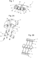
- the two connecting rods and their shoulder are arranged within the recesses of the central link so as to curve the bracelet in a direction towards the inside of the bracelet as illustrated in Figure 6A .
- the two connecting rods are positioned angularly in different ways in the two through holes. In the flat position, the shoulder 5 for the two connecting rods 4 rests on the inner wall 6b of the recess 6 ( Figure 4A ).
- the recess 6 hollowed out at the end of the through hole also flares out in an arc of a circle with the arc of a circle 6a of the recess 6 having a length greater than that of the arc of a circle 5a of the shoulder 5 to allow the latter to pivot within the recess.
- the length of the arc of a circle of the recess relative to that of the arc of a circle of the shoulder makes it possible to define the range of angular displacement of the central link relative to the connecting rod.
- the amplitude of rotation of the central link relative to the connecting rod is less than or equal to 150°, preferably less than or equal to 60°.
- each central link 2 has a rotation amplitude of 60°, which allows, after rotation of two adjacent central links by 60°, to have a pivot of 120° between two adjacent lateral links 3 as shown diagrammatically in Figures 5C and 6C .
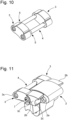
- the side links 3 have two circular ears 3c which are positioned in a circular recess 2c formed in a protruding part 2b of the central link 3 arranged between the two through holes 2a ( 5D figures And 11 ).
- the protruding part 2b of the central link 2 is inserted between two side links 3 to form respectively the second row 9 and the third row 10 with the side links 3 ( figure 1 ).
- the protruding portion 2b of the central link 2 has a thickness substantially equal to that of the lateral link 3.
- the ears 3c of the lateral links 3 are housed without contact within the circular hollow 2c of the protruding portion 2b of the central links.
- the ears 3c of the lateral link are surmounted by a recessed portion 3d relative to the latter ( Figure 5D ).
- This recessed portion 3d is positioned without contact opposite the summit 2d of the protruding part 2b which overhangs the hollow 2c.
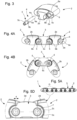
- the assembly of the different elements of the bracelet is done as follows. It can be done as in the Figure 2A with all the recesses of the central links which are hollowed out on the same face of the link, with therefore all the connecting rods provided with the shoulder which are introduced via this face. It can also be made as on the Figure 2B with a recess hollowed out alternately on one face and on the other face of the central link, the connecting rod being introduced with this same alternation.
- the assembly principle is substantially the same in both cases and described in relation to the Figures 2A And 8 has 11 .
- There figure 10 presents a simplified view where the central link is absent.
- the two connecting rods 4, and more specifically the part with the flats 4a, are mounted in the respective holes 3a of the side link 3 with the shoulder 5 of the connecting rod 4 which is positioned with an axial clearance opposite the side link 3.
- the fixing between the connecting rods 4 and the side link 3 is carried out using the screws 7 which are introduced into one end of the through hole 3a of the side link into the hollow of the connecting rod.
- the fixing can be carried out by gluing.
- a central link 2 is threaded onto one of the connecting rods 4 with the shoulder 5 which is housed with an axial clearance in the recess 6 of the central link 2 and rests on the inner wall 6b of the recess.
Landscapes
- Pivots And Pivotal Connections (AREA)
- Adornments (AREA)
- Toys (AREA)
- Prostheses (AREA)
Claims (16)
- Armband (1), umfassend:- eine erste Reihe (8) mit mindestens einem zentralen Kettenglied (2), das mit zwei Durchgangslöchern (2a), Löcher (2a) des zentralen Kettenglieds (2) genannt, versehen ist,- eine zweite Reihe (9) und eine dritte Reihe (10), die jeweils beiderseits der ersten Reihe (8) angeordnet sind, wobei die zweite Reihe (9) und die dritte Reihe (10) jeweils mindestens ein seitliches Kettenglied (3) umfassen, wobei das seitliche Kettenglied (3) mit zwei Löchern (3a), Löcher (3a) des seitlichen Kettenglieds (3) genannt, versehen ist, wobei ein Loch (3a) des seitlichen Kettenglieds (3) der zweiten Reihe (9) zu einem Loch (2a) des zentralen Kettenglieds (2) der ersten Reihe (8) und zu einem Loch (3a) des seitlichen Kettenglieds (3) der dritten Reihe (10) ausgerichtet ist, um eine Einheit mit drei ausgerichteten Löchern zu bilden,- eine Verbindungswelle (4), die in den drei ausgerichteten Löchern positioniert ist, wobei die Verbindungswelle (4) in Bezug auf das seitliche Kettenglied (3) der zweiten Reihe (9) und der dritten Reihe (10) festmontiert ist und eine Achse bildet, um die herum das zentrale Kettenglied (2) schwenkbar montiert ist,wobei das Armband (1) dadurch gekennzeichnet ist, dass die Verbindungswelle (4) eine Schulter (5) umfasst, und dadurch, dass jedes Loch (2a) des zentralen Kettenglieds (2) an einem seiner Enden in eine in dem zentralen Kettenglied (2) ausgehölte Aussparung (6) mündet, wobei die Aussparung (6) durch eine erste, Innenwand genannte Wand (6b), da sie dem Zentrum des zentralen Kettenglieds (2) am nächsten liegt, und durch eine zweite, Außenwand genannte Wand (6c), da sie vom Zentrum des zentralen Kettenglieds (2) am weitesten entfernt ist, begrenzt ist, wobei die erste Wand (6b) und die zweite Wand (6c) als erster Anschlag und als zweiter Anschlag für die Schulter (5) dienen, wenn das zentrale Kettenglied (2) um die Verbindungswelle (4) schwenkt, um die Amplitude der Drehung des zentralen Kettenglieds (2) um die Verbindungswelle (4) herum zu begrenzen.
- Armband (1) nach Anspruch 1, dadurch gekennzeichnet, dass sich die Schulter (5) der Verbindungswelle (4) radial in einen Kreisbogen (5a) von der Verbindungswelle (4) aus aufweitet, wobei der Kreisbogen (5a) über eine erste Flanke (5b) und eine zweite Flanke (5c) mit der Verbindungswelle (4) verbunden ist, und dadurch, dass die Aussparung (6) auch eine in einen Kreisbogen (6a) aufgeweitete Form aufweist, wobei die Länge des Kreisbogens (6a) größer ist als die des Kreisbogens (5a) der Schulter (5), um das Schwenken der Schulter (5) innerhalb der Aussparung (6) zu ermöglichen.
- Armband (1) nach einem der vorstehenden Ansprüche, dadurch gekennzeichnet, dass die Amplitude der Drehung des zentralen Kettenglieds (2) um die Verbindungswelle (4) herum kleiner oder gleich 150°, vorzugsweise kleiner oder gleich 60° ist.
- Armband (1) nach einem der vorstehenden Ansprüche, dadurch gekennzeichnet, dass, wenn das zentrale Kettenglied (2) eine Drehamplitude von Null aufweist, das heißt, wenn die durch das zentrale Kettenglied (2) der ersten Reihe (8) und das mindestens eine seitliche Kettenglied (3) der zweiten Reihe (9) und der dritten Reihe (10) gebildete Einheit in derselben Ebene liegt, sich die Schulter (5) an der Innenwand (6b) der Aussparung (6) anlegt, und dadurch, dass, wenn das zentrale Kettenglied (2) seine maximale Drehamplitude erreicht hat, sich die Schulter (5) an der Außenwand (6c) der Aussparung (6) anlegt.
- Armband (1) nach einem der vorstehenden Ansprüche, dadurch gekennzeichnet, dass die Verbindungswelle (4) an jedem ihrer Enden einen Abschnitt mit einem nicht kreisförmigen Querschnitt aufweist, und dadurch, dass jedes Loch (3a) des seitlichen Kettenglieds (3) auch einen Abschnitt mit einem nicht kreisförmigen Querschnitt aufweist, wobei sich der Abschnitt mit einem nicht kreisförmigen Querschnitt der Verbindungswelle (4) in den Abschnitt mit einem nicht kreisförmigen Querschnitt des Lochs (3a) des seitlichen Kettenglieds (3) einlegt, sodass die Verbindungswelle (4) in Bezug auf das Seitenglied (3) festmontiert ist.
- Armband (1) nach dem vorstehenden Anspruch, dadurch gekennzeichnet, dass der Abschnitt mit einem nicht kreisförmigen Querschnitt der Verbindungswelle (4) mindestens eine Abflachung (4a) beinhaltet, die sich an eine Ebene (3b) des Abschnitts mit einem nicht kreisförmigen Querschnitt des seitlichen Kettenglieds (3) anlegt.
- Armband (1) nach einem der vorstehenden Ansprüche, dadurch gekennzeichnet, dass das zentrale Kettenglied (2) an jedem seiner Enden zwischen den beiden Durchgangslöchern (2a) einen vorspringenden Teil (2b) beinhaltet, der sich in der zweiten Reihe (9) und in der dritten Reihe (10) neben dem seitlichen Kettenglied (3) erstreckt.
- Armband (1) nach dem vorstehenden Anspruch, dadurch gekennzeichnet, dass der vorspringende Teil (2b) des zentralen Kettenglieds (2) eine Dicke aufweist, die im Wesentlichen gleich jener des seitlichen Kettenglieds (3) ist.
- Armband (1) nach Anspruch 7 oder 8, dadurch gekennzeichnet, dass das seitliche Kettenglied (3) zwei kreisförmige Ohren (3c) beinhaltet, wobei sich ein kreisförmiges Ohr (3c) berührungslos in eine kreisförmige Vertiefung (2c) einlegt, die in dem vorspringenden Teil (2b) des zentralen Kettenglieds (2) gebildet ist.
- Armband (1) nach einem der vorstehenden Ansprüche, dadurch gekennzeichnet, dass die beiden Löcher (3a) des seitlichen Kettenglieds (3) durchgängig sind und dadurch, dass die Befestigung zwischen dem seitlichen Kettenglied (3) und der Verbindungswelle (4) mit einer Schraube (7) erfolgt, die sich am Ende des Durchgangsloches (3a) auf der dem zentralen Kettenglied (2) gegenüberliegenden Seite positioniert.
- Armband (1) nach einem der Ansprüche 1 bis 9, dadurch gekennzeichnet, dass die beiden Löcher (3a) des seitlichen Kettenglieds (3) Durchgangs- oder Sacklöcher sind, und dadurch, dass die Befestigung zwischen dem seitlichen Kettenglied (3) und der Verbindungswelle (4) mit Klebstoff erfolgt.
- Armband (1) nach einem der vorstehenden Ansprüche, dadurch gekennzeichnet, dass das zentrale Kettenglied (2) und/oder das seitliche Kettenglied (3) zumindest teilweise aus einem Werkstoff bestehen/besteht, dessen Härte gleich oder größer als 1.200 HV ist.
- Armband (1) nach einem der vorstehenden Ansprüche, dadurch gekennzeichnet, dass die Verbindungswelle (4) eine Härte von weniger als 1.200 HV aufweist.
- Armband (1) nach einem der vorstehenden Ansprüche, dadurch gekennzeichnet, dass die Aussparung (6) des zentralen Kettenglieds (2) für die beiden Durchgangslöcher (2a) auf derselben Seite des zentralen Kettenglieds (2) ausgehöhlt ist.
- Armband (1) nach einem der Ansprüche 1 bis 13, dadurch gekennzeichnet, dass die Aussparung (6) des zentralen Kettenglieds (2) für die beiden Durchgangslöcher (2a) jeweils auf einer Seite des zentralen Kettenglieds (2) für ein Durchgangsloch (2a) und auf einer gegenüberliegenden Seite des zentralen Kettenglieds (2) für das andere Durchgangsloch (2a) ausgehöhlt ist.
- Teil, insbesondere ein Uhrmachereiteil, welches das Armband (1) nach einem der vorstehenden Ansprüche umfasst.
Priority Applications (4)
| Application Number | Priority Date | Filing Date | Title |
|---|---|---|---|
| EP22182358.6A EP4298948B1 (de) | 2022-06-30 | 2022-06-30 | Armband mit kettengliedern aus hartem material |
| US18/163,985 US12178297B2 (en) | 2022-06-30 | 2023-02-03 | Wristlet with links made of a hard material |
| JP2023019725A JP7620037B2 (ja) | 2022-06-30 | 2023-02-13 | 硬質材料で作られたリンク付きリストレット |
| CN202310800223.5A CN117322709A (zh) | 2022-06-30 | 2023-06-30 | 具有由硬质材料制成的节的腕带 |
Applications Claiming Priority (1)
| Application Number | Priority Date | Filing Date | Title |
|---|---|---|---|
| EP22182358.6A EP4298948B1 (de) | 2022-06-30 | 2022-06-30 | Armband mit kettengliedern aus hartem material |
Publications (2)
| Publication Number | Publication Date |
|---|---|
| EP4298948A1 EP4298948A1 (de) | 2024-01-03 |
| EP4298948B1 true EP4298948B1 (de) | 2025-02-26 |
Family
ID=82493869
Family Applications (1)
| Application Number | Title | Priority Date | Filing Date |
|---|---|---|---|
| EP22182358.6A Active EP4298948B1 (de) | 2022-06-30 | 2022-06-30 | Armband mit kettengliedern aus hartem material |
Country Status (4)
| Country | Link |
|---|---|
| US (1) | US12178297B2 (de) |
| EP (1) | EP4298948B1 (de) |
| JP (1) | JP7620037B2 (de) |
| CN (1) | CN117322709A (de) |
Families Citing this family (1)
| Publication number | Priority date | Publication date | Assignee | Title |
|---|---|---|---|---|
| EP4018874B1 (de) * | 2020-12-22 | 2024-03-27 | Comadur S.A. | Zusammenbau von elementen wie den kettengliedern eines armbands |
Family Cites Families (20)
| Publication number | Priority date | Publication date | Assignee | Title |
|---|---|---|---|---|
| US421136A (en) * | 1890-02-11 | Hoffs | ||
| US1445564A (en) * | 1920-08-09 | 1923-02-13 | Frank R Stafford | Bracelet coupling |
| US1995517A (en) * | 1933-11-04 | 1935-03-26 | Edwin A Neugass | Bracelet catch |
| JPS5235731Y2 (de) * | 1972-04-14 | 1977-08-15 | ||
| JPS5931911U (ja) * | 1982-08-26 | 1984-02-28 | シチズン時計株式会社 | 時計バンドの中留構造 |
| CH661184A5 (en) * | 1984-12-19 | 1987-07-15 | Finger H Fa | Bracelet, particularly a watch bracelet, and method for manufacturing this bracelet |
| JP2536491Y2 (ja) * | 1990-05-14 | 1997-05-21 | シチズン時計株式会社 | 時計バンドの構造 |
| JPH0715449Y2 (ja) * | 1992-06-26 | 1995-04-12 | 株式会社原製作所 | リング連結式時計バンドにおけるアジャスト部の構造 |
| JPH0613519U (ja) * | 1992-07-31 | 1994-02-22 | 上尾精密株式会社 | バンドの構造 |
| JPH0767707A (ja) * | 1993-09-06 | 1995-03-14 | Seiko Epson Corp | 時計バンドの駒 |
| DK0921742T3 (da) * | 1996-08-29 | 2001-10-01 | Tag Heuer Sa | Urarmbånd med hængslede led og ur med et sådant armbånd |
| JP2014236781A (ja) * | 2013-06-06 | 2014-12-18 | カシオ計算機株式会社 | 部材連結構造、バンド取付構造、および時計 |
| KR102014445B1 (ko) * | 2013-09-27 | 2019-08-29 | 삼성전자주식회사 | 착용형 기기 |
| KR20160103072A (ko) * | 2013-12-24 | 2016-08-31 | 폴리에라 코퍼레이션 | 가요성 전자 부품용 지지 구조체 |
| EP2915445B1 (de) * | 2014-03-04 | 2016-12-14 | Rolex Sa | Vorrichtung und Verfahren zum drehbaren Zusammenbau von mindestens zwei Teilen, und Einheit aus den zwei zusammengebauten Teilen |
| EP3488769B1 (de) * | 2016-07-19 | 2020-08-19 | Shenzhen Royole Technologies Co., Ltd. | Flexible vorrichtung |
| WO2020000420A1 (zh) * | 2018-06-29 | 2020-01-02 | 谭博闻 | 一种接口式戒指 |
| CN208523938U (zh) * | 2018-06-29 | 2019-02-22 | 北京小米移动软件有限公司 | 销钉组件及可穿戴设备 |
| CN212139610U (zh) * | 2020-04-23 | 2020-12-15 | 广东小天才科技有限公司 | 一种表带及手表 |
| EP4018874B1 (de) * | 2020-12-22 | 2024-03-27 | Comadur S.A. | Zusammenbau von elementen wie den kettengliedern eines armbands |
-
2022
- 2022-06-30 EP EP22182358.6A patent/EP4298948B1/de active Active
-
2023
- 2023-02-03 US US18/163,985 patent/US12178297B2/en active Active
- 2023-02-13 JP JP2023019725A patent/JP7620037B2/ja active Active
- 2023-06-30 CN CN202310800223.5A patent/CN117322709A/zh active Pending
Also Published As
| Publication number | Publication date |
|---|---|
| US12178297B2 (en) | 2024-12-31 |
| JP2024006930A (ja) | 2024-01-17 |
| US20240000201A1 (en) | 2024-01-04 |
| JP7620037B2 (ja) | 2025-01-22 |
| EP4298948A1 (de) | 2024-01-03 |
| CN117322709A (zh) | 2024-01-02 |
Similar Documents
| Publication | Publication Date | Title |
|---|---|---|
| EP1738229B1 (de) | Krone für eine uhr mit einer entriegelungseinrichtung | |
| EP2440085B1 (de) | Armband mit Gelenkgliedern | |
| EP3220211B1 (de) | Stosssicherungssystem mit rotationssperre | |
| EP4298948B1 (de) | Armband mit kettengliedern aus hartem material | |
| EP3176650B1 (de) | Schutz einer uhrkomponente aus mikro-bearbeitbarem material | |
| EP4298949B1 (de) | Armband mit kettengliedern aus hartem material | |
| EP2394074A1 (de) | Rotierender linearaktuator mit optimierten walzen | |
| CH719850A2 (fr) | Bracelet avec maillons en matériau dur. | |
| BE1016129A3 (fr) | Anneau a double articulation pour le levage de charge. | |
| EP0949426B1 (de) | Einheit aus zwei mit zwei Freiheitsgraden miteinander angelenkten Elementen | |
| EP3786720B1 (de) | Uhrkomponente zur aufnahme eines organs durch einpressen | |
| EP3653074B1 (de) | Zusammenbau von elementen, wie die kettenglieder eines armbands | |
| EP3023844A1 (de) | Flexible Spiralrolle | |
| CH719851A2 (fr) | Bracelet avec maillons en matériau dur. | |
| EP3519902B1 (de) | Achsträgerlager mit reduziertem abrieb | |
| EP3671364A1 (de) | Elastisches halterungsorgan für die befestigung einer uhrenkomponente auf einem halteelement | |
| EP3711622A1 (de) | Armband mit kettengliedern | |
| EP4407382A1 (de) | Spiralfeder für uhrwerk | |
| EP0167799A1 (de) | Gliederarmband | |
| EP3822708B1 (de) | Uhrwerkmechanismus, der eine antriebsvorrichtung zum drehen eines organs durch ein anderes umfasst | |
| EP4609746A1 (de) | Dehnbarer dekorativer artikel | |
| CH717059A2 (fr) | Masselotte de réglage. | |
| EP0509222B1 (de) | Gliederarmband, insbesonders für Uhren | |
| EP0625453A1 (de) | Gelenk für Schwenkbügel eines Scheibenwischers | |
| CH719189A2 (fr) | Chaton de sertissage et procédé de sertissage d'un ensemble décoratif. |
Legal Events
| Date | Code | Title | Description |
|---|---|---|---|
| PUAI | Public reference made under article 153(3) epc to a published international application that has entered the european phase |
Free format text: ORIGINAL CODE: 0009012 |
|
| STAA | Information on the status of an ep patent application or granted ep patent |
Free format text: STATUS: THE APPLICATION HAS BEEN PUBLISHED |
|
| AK | Designated contracting states |
Kind code of ref document: A1 Designated state(s): AL AT BE BG CH CY CZ DE DK EE ES FI FR GB GR HR HU IE IS IT LI LT LU LV MC MK MT NL NO PL PT RO RS SE SI SK SM TR |
|
| P01 | Opt-out of the competence of the unified patent court (upc) registered |
Effective date: 20240319 |
|
| STAA | Information on the status of an ep patent application or granted ep patent |
Free format text: STATUS: REQUEST FOR EXAMINATION WAS MADE |
|
| 17P | Request for examination filed |
Effective date: 20240703 |
|
| RBV | Designated contracting states (corrected) |
Designated state(s): AL AT BE BG CH CY CZ DE DK EE ES FI FR GB GR HR HU IE IS IT LI LT LU LV MC MK MT NL NO PL PT RO RS SE SI SK SM TR |
|
| GRAP | Despatch of communication of intention to grant a patent |
Free format text: ORIGINAL CODE: EPIDOSNIGR1 |
|
| STAA | Information on the status of an ep patent application or granted ep patent |
Free format text: STATUS: GRANT OF PATENT IS INTENDED |
|
| RIC1 | Information provided on ipc code assigned before grant |
Ipc: A44C 5/10 20060101AFI20240930BHEP |
|
| INTG | Intention to grant announced |
Effective date: 20241031 |
|
| GRAS | Grant fee paid |
Free format text: ORIGINAL CODE: EPIDOSNIGR3 |
|
| GRAA | (expected) grant |
Free format text: ORIGINAL CODE: 0009210 |
|
| STAA | Information on the status of an ep patent application or granted ep patent |
Free format text: STATUS: THE PATENT HAS BEEN GRANTED |
|
| AK | Designated contracting states |
Kind code of ref document: B1 Designated state(s): AL AT BE BG CH CY CZ DE DK EE ES FI FR GB GR HR HU IE IS IT LI LT LU LV MC MK MT NL NO PL PT RO RS SE SI SK SM TR |
|
| REG | Reference to a national code |
Ref country code: GB Ref legal event code: FG4D Free format text: NOT ENGLISH |
|
| REG | Reference to a national code |
Ref country code: CH Ref legal event code: EP |
|
| REG | Reference to a national code |
Ref country code: DE Ref legal event code: R096 Ref document number: 602022011013 Country of ref document: DE |
|
| REG | Reference to a national code |
Ref country code: IE Ref legal event code: FG4D Free format text: LANGUAGE OF EP DOCUMENT: FRENCH |
|
| REG | Reference to a national code |
Ref country code: NL Ref legal event code: MP Effective date: 20250226 |
|
| PG25 | Lapsed in a contracting state [announced via postgrant information from national office to epo] |
Ref country code: RS Free format text: LAPSE BECAUSE OF FAILURE TO SUBMIT A TRANSLATION OF THE DESCRIPTION OR TO PAY THE FEE WITHIN THE PRESCRIBED TIME-LIMIT Effective date: 20250526 |
|
| PG25 | Lapsed in a contracting state [announced via postgrant information from national office to epo] |
Ref country code: FI Free format text: LAPSE BECAUSE OF FAILURE TO SUBMIT A TRANSLATION OF THE DESCRIPTION OR TO PAY THE FEE WITHIN THE PRESCRIBED TIME-LIMIT Effective date: 20250226 |
|
| PG25 | Lapsed in a contracting state [announced via postgrant information from national office to epo] |
Ref country code: PL Free format text: LAPSE BECAUSE OF FAILURE TO SUBMIT A TRANSLATION OF THE DESCRIPTION OR TO PAY THE FEE WITHIN THE PRESCRIBED TIME-LIMIT Effective date: 20250226 |
|
| PGFP | Annual fee paid to national office [announced via postgrant information from national office to epo] |
Ref country code: DE Payment date: 20250520 Year of fee payment: 4 |
|
| PG25 | Lapsed in a contracting state [announced via postgrant information from national office to epo] |
Ref country code: ES Free format text: LAPSE BECAUSE OF FAILURE TO SUBMIT A TRANSLATION OF THE DESCRIPTION OR TO PAY THE FEE WITHIN THE PRESCRIBED TIME-LIMIT Effective date: 20250226 |
|
| REG | Reference to a national code |
Ref country code: LT Ref legal event code: MG9D |
|
| PG25 | Lapsed in a contracting state [announced via postgrant information from national office to epo] |
Ref country code: IS Free format text: LAPSE BECAUSE OF FAILURE TO SUBMIT A TRANSLATION OF THE DESCRIPTION OR TO PAY THE FEE WITHIN THE PRESCRIBED TIME-LIMIT Effective date: 20250626 Ref country code: NO Free format text: LAPSE BECAUSE OF FAILURE TO SUBMIT A TRANSLATION OF THE DESCRIPTION OR TO PAY THE FEE WITHIN THE PRESCRIBED TIME-LIMIT Effective date: 20250526 |
|
| PG25 | Lapsed in a contracting state [announced via postgrant information from national office to epo] |
Ref country code: NL Free format text: LAPSE BECAUSE OF FAILURE TO SUBMIT A TRANSLATION OF THE DESCRIPTION OR TO PAY THE FEE WITHIN THE PRESCRIBED TIME-LIMIT Effective date: 20250226 |
|
| PG25 | Lapsed in a contracting state [announced via postgrant information from national office to epo] |
Ref country code: HR Free format text: LAPSE BECAUSE OF FAILURE TO SUBMIT A TRANSLATION OF THE DESCRIPTION OR TO PAY THE FEE WITHIN THE PRESCRIBED TIME-LIMIT Effective date: 20250226 |
|
| PG25 | Lapsed in a contracting state [announced via postgrant information from national office to epo] |
Ref country code: PT Free format text: LAPSE BECAUSE OF FAILURE TO SUBMIT A TRANSLATION OF THE DESCRIPTION OR TO PAY THE FEE WITHIN THE PRESCRIBED TIME-LIMIT Effective date: 20250626 Ref country code: LV Free format text: LAPSE BECAUSE OF FAILURE TO SUBMIT A TRANSLATION OF THE DESCRIPTION OR TO PAY THE FEE WITHIN THE PRESCRIBED TIME-LIMIT Effective date: 20250226 |
|
| PGFP | Annual fee paid to national office [announced via postgrant information from national office to epo] |
Ref country code: FR Payment date: 20250520 Year of fee payment: 4 |
|
| PG25 | Lapsed in a contracting state [announced via postgrant information from national office to epo] |
Ref country code: GR Free format text: LAPSE BECAUSE OF FAILURE TO SUBMIT A TRANSLATION OF THE DESCRIPTION OR TO PAY THE FEE WITHIN THE PRESCRIBED TIME-LIMIT Effective date: 20250527 Ref country code: BG Free format text: LAPSE BECAUSE OF FAILURE TO SUBMIT A TRANSLATION OF THE DESCRIPTION OR TO PAY THE FEE WITHIN THE PRESCRIBED TIME-LIMIT Effective date: 20250226 |
|
| REG | Reference to a national code |
Ref country code: AT Ref legal event code: MK05 Ref document number: 1769759 Country of ref document: AT Kind code of ref document: T Effective date: 20250226 |
|
| PG25 | Lapsed in a contracting state [announced via postgrant information from national office to epo] |
Ref country code: SE Free format text: LAPSE BECAUSE OF FAILURE TO SUBMIT A TRANSLATION OF THE DESCRIPTION OR TO PAY THE FEE WITHIN THE PRESCRIBED TIME-LIMIT Effective date: 20250226 |
|
| PG25 | Lapsed in a contracting state [announced via postgrant information from national office to epo] |
Ref country code: SM Free format text: LAPSE BECAUSE OF FAILURE TO SUBMIT A TRANSLATION OF THE DESCRIPTION OR TO PAY THE FEE WITHIN THE PRESCRIBED TIME-LIMIT Effective date: 20250226 |
|
| PG25 | Lapsed in a contracting state [announced via postgrant information from national office to epo] |
Ref country code: DK Free format text: LAPSE BECAUSE OF FAILURE TO SUBMIT A TRANSLATION OF THE DESCRIPTION OR TO PAY THE FEE WITHIN THE PRESCRIBED TIME-LIMIT Effective date: 20250226 |
|
| PGFP | Annual fee paid to national office [announced via postgrant information from national office to epo] |
Ref country code: IT Payment date: 20250630 Year of fee payment: 4 |
|
| PG25 | Lapsed in a contracting state [announced via postgrant information from national office to epo] |
Ref country code: AT Free format text: LAPSE BECAUSE OF FAILURE TO SUBMIT A TRANSLATION OF THE DESCRIPTION OR TO PAY THE FEE WITHIN THE PRESCRIBED TIME-LIMIT Effective date: 20250226 |
|
| PGFP | Annual fee paid to national office [announced via postgrant information from national office to epo] |
Ref country code: CH Payment date: 20250701 Year of fee payment: 4 |
|
| PG25 | Lapsed in a contracting state [announced via postgrant information from national office to epo] |
Ref country code: EE Free format text: LAPSE BECAUSE OF FAILURE TO SUBMIT A TRANSLATION OF THE DESCRIPTION OR TO PAY THE FEE WITHIN THE PRESCRIBED TIME-LIMIT Effective date: 20250226 Ref country code: CZ Free format text: LAPSE BECAUSE OF FAILURE TO SUBMIT A TRANSLATION OF THE DESCRIPTION OR TO PAY THE FEE WITHIN THE PRESCRIBED TIME-LIMIT Effective date: 20250226 |
|
| PG25 | Lapsed in a contracting state [announced via postgrant information from national office to epo] |
Ref country code: RO Free format text: LAPSE BECAUSE OF FAILURE TO SUBMIT A TRANSLATION OF THE DESCRIPTION OR TO PAY THE FEE WITHIN THE PRESCRIBED TIME-LIMIT Effective date: 20250226 |
|
| PG25 | Lapsed in a contracting state [announced via postgrant information from national office to epo] |
Ref country code: SK Free format text: LAPSE BECAUSE OF FAILURE TO SUBMIT A TRANSLATION OF THE DESCRIPTION OR TO PAY THE FEE WITHIN THE PRESCRIBED TIME-LIMIT Effective date: 20250226 |
|
| REG | Reference to a national code |
Ref country code: DE Ref legal event code: R097 Ref document number: 602022011013 Country of ref document: DE |
|
| PLBE | No opposition filed within time limit |
Free format text: ORIGINAL CODE: 0009261 |
|
| STAA | Information on the status of an ep patent application or granted ep patent |
Free format text: STATUS: NO OPPOSITION FILED WITHIN TIME LIMIT |
|
| PG25 | Lapsed in a contracting state [announced via postgrant information from national office to epo] |
Ref country code: MC Free format text: LAPSE BECAUSE OF FAILURE TO SUBMIT A TRANSLATION OF THE DESCRIPTION OR TO PAY THE FEE WITHIN THE PRESCRIBED TIME-LIMIT Effective date: 20250226 |
|
| 26N | No opposition filed |
Effective date: 20251127 |