EP4298046B1 - Anordnung eines krans an einer schwimmenden windenergieanlage - Google Patents
Anordnung eines krans an einer schwimmenden windenergieanlage Download PDFInfo
- Publication number
- EP4298046B1 EP4298046B1 EP22772510.8A EP22772510A EP4298046B1 EP 4298046 B1 EP4298046 B1 EP 4298046B1 EP 22772510 A EP22772510 A EP 22772510A EP 4298046 B1 EP4298046 B1 EP 4298046B1
- Authority
- EP
- European Patent Office
- Prior art keywords
- crane
- base structure
- boom
- rotatable
- crane base
- Prior art date
- Legal status (The legal status is an assumption and is not a legal conclusion. Google has not performed a legal analysis and makes no representation as to the accuracy of the status listed.)
- Active
Links
Images


Classifications
-
- B—PERFORMING OPERATIONS; TRANSPORTING
- B66—HOISTING; LIFTING; HAULING
- B66C—CRANES; LOAD-ENGAGING ELEMENTS OR DEVICES FOR CRANES, CAPSTANS, WINCHES, OR TACKLES
- B66C23/00—Cranes comprising essentially a beam, boom, or triangular structure acting as a cantilever and mounted for translatory of swinging movements in vertical or horizontal planes or a combination of such movements, e.g. jib-cranes, derricks, tower cranes
- B66C23/18—Cranes comprising essentially a beam, boom, or triangular structure acting as a cantilever and mounted for translatory of swinging movements in vertical or horizontal planes or a combination of such movements, e.g. jib-cranes, derricks, tower cranes specially adapted for use in particular purposes
- B66C23/36—Cranes comprising essentially a beam, boom, or triangular structure acting as a cantilever and mounted for translatory of swinging movements in vertical or horizontal planes or a combination of such movements, e.g. jib-cranes, derricks, tower cranes specially adapted for use in particular purposes mounted on road or rail vehicles; Manually-movable jib-cranes for use in workshops; Floating cranes
- B66C23/52—Floating cranes
-
- B—PERFORMING OPERATIONS; TRANSPORTING
- B66—HOISTING; LIFTING; HAULING
- B66C—CRANES; LOAD-ENGAGING ELEMENTS OR DEVICES FOR CRANES, CAPSTANS, WINCHES, OR TACKLES
- B66C23/00—Cranes comprising essentially a beam, boom, or triangular structure acting as a cantilever and mounted for translatory of swinging movements in vertical or horizontal planes or a combination of such movements, e.g. jib-cranes, derricks, tower cranes
- B66C23/18—Cranes comprising essentially a beam, boom, or triangular structure acting as a cantilever and mounted for translatory of swinging movements in vertical or horizontal planes or a combination of such movements, e.g. jib-cranes, derricks, tower cranes specially adapted for use in particular purposes
- B66C23/26—Cranes comprising essentially a beam, boom, or triangular structure acting as a cantilever and mounted for translatory of swinging movements in vertical or horizontal planes or a combination of such movements, e.g. jib-cranes, derricks, tower cranes specially adapted for use in particular purposes for use on building sites; constructed, e.g. with separable parts, to facilitate rapid assembly or dismantling, for operation at successively higher levels, for transport by road or rail
- B66C23/34—Self-erecting cranes, i.e. with hoisting gear adapted for crane erection purposes
- B66C23/344—Self-erecting cranes, i.e. with hoisting gear adapted for crane erection purposes adapted for transport purposes
-
- B—PERFORMING OPERATIONS; TRANSPORTING
- B66—HOISTING; LIFTING; HAULING
- B66C—CRANES; LOAD-ENGAGING ELEMENTS OR DEVICES FOR CRANES, CAPSTANS, WINCHES, OR TACKLES
- B66C23/00—Cranes comprising essentially a beam, boom, or triangular structure acting as a cantilever and mounted for translatory of swinging movements in vertical or horizontal planes or a combination of such movements, e.g. jib-cranes, derricks, tower cranes
- B66C23/18—Cranes comprising essentially a beam, boom, or triangular structure acting as a cantilever and mounted for translatory of swinging movements in vertical or horizontal planes or a combination of such movements, e.g. jib-cranes, derricks, tower cranes specially adapted for use in particular purposes
- B66C23/185—Cranes comprising essentially a beam, boom, or triangular structure acting as a cantilever and mounted for translatory of swinging movements in vertical or horizontal planes or a combination of such movements, e.g. jib-cranes, derricks, tower cranes specially adapted for use in particular purposes for use erecting wind turbines
-
- F—MECHANICAL ENGINEERING; LIGHTING; HEATING; WEAPONS; BLASTING
- F03—MACHINES OR ENGINES FOR LIQUIDS; WIND, SPRING, OR WEIGHT MOTORS; PRODUCING MECHANICAL POWER OR A REACTIVE PROPULSIVE THRUST, NOT OTHERWISE PROVIDED FOR
- F03D—WIND MOTORS
- F03D13/00—Assembly, mounting or commissioning of wind motors; Arrangements specially adapted for transporting wind motor components
- F03D13/20—Arrangements for mounting or supporting wind motors; Masts or towers for wind motors
- F03D13/25—Arrangements for mounting or supporting wind motors; Masts or towers for wind motors specially adapted for offshore installation
- F03D13/256—Arrangements for mounting or supporting wind motors; Masts or towers for wind motors specially adapted for offshore installation on a floating support, i.e. floating wind motors
-
- F—MECHANICAL ENGINEERING; LIGHTING; HEATING; WEAPONS; BLASTING
- F05—INDEXING SCHEMES RELATING TO ENGINES OR PUMPS IN VARIOUS SUBCLASSES OF CLASSES F01-F04
- F05B—INDEXING SCHEME RELATING TO WIND, SPRING, WEIGHT, INERTIA OR LIKE MOTORS, TO MACHINES OR ENGINES FOR LIQUIDS COVERED BY SUBCLASSES F03B, F03D AND F03G
- F05B2240/00—Components
- F05B2240/90—Mounting on supporting structures or systems
- F05B2240/95—Mounting on supporting structures or systems offshore
-
- Y—GENERAL TAGGING OF NEW TECHNOLOGICAL DEVELOPMENTS; GENERAL TAGGING OF CROSS-SECTIONAL TECHNOLOGIES SPANNING OVER SEVERAL SECTIONS OF THE IPC; TECHNICAL SUBJECTS COVERED BY FORMER USPC CROSS-REFERENCE ART COLLECTIONS [XRACs] AND DIGESTS
- Y02—TECHNOLOGIES OR APPLICATIONS FOR MITIGATION OR ADAPTATION AGAINST CLIMATE CHANGE
- Y02E—REDUCTION OF GREENHOUSE GAS [GHG] EMISSIONS, RELATED TO ENERGY GENERATION, TRANSMISSION OR DISTRIBUTION
- Y02E10/00—Energy generation through renewable energy sources
- Y02E10/70—Wind energy
- Y02E10/72—Wind turbines with rotation axis in wind direction
-
- Y—GENERAL TAGGING OF NEW TECHNOLOGICAL DEVELOPMENTS; GENERAL TAGGING OF CROSS-SECTIONAL TECHNOLOGIES SPANNING OVER SEVERAL SECTIONS OF THE IPC; TECHNICAL SUBJECTS COVERED BY FORMER USPC CROSS-REFERENCE ART COLLECTIONS [XRACs] AND DIGESTS
- Y02—TECHNOLOGIES OR APPLICATIONS FOR MITIGATION OR ADAPTATION AGAINST CLIMATE CHANGE
- Y02E—REDUCTION OF GREENHOUSE GAS [GHG] EMISSIONS, RELATED TO ENERGY GENERATION, TRANSMISSION OR DISTRIBUTION
- Y02E10/00—Energy generation through renewable energy sources
- Y02E10/70—Wind energy
- Y02E10/727—Offshore wind turbines
Definitions
- This invention relates to a method for arranging a crane machine on a wind power station that floats in open water.
- the invention also relates to a wind power station adapted for such a crane arrangement.
- Such a wind turbine may have a fixed underwater foundation or, in particular at water depths larger than around 50-60 m, may be floating anchored to the bottom.
- the turbine tower may extend up to, say, 150 m above sea level and each turbine blade may be more than 100 m long.
- a jack-up vessel provided with a sufficiently large crane for handling e.g. dismounting and remounting of a damaged and repaired turbine blade.
- Such vessels can stand on the bottom and lift itself above the sea level and can thus work in a stable way unaffected by the waves. Since both the turbine tower and the crane in such a case are fixed in relation to each other, maintenance and repair can be carried in principally the same way as for land-based wind turbines.
- Document US 2019/218075 describes such a crane and its use, mounted on a jack-up vessel and able to carry out at maintenance works on wind turbines. It comprises at least a rotatable crane base structure, a main boom and hoist components for lifting and lowering materials.
- the crane is configured to lift/lower heavy wind turbine elements to/from an upper part of a wind turbine.
- the crane can be transported to the jack-up vessel in a partly disassembled state.
- Non-fixed crane vessels such as heavy lift vessels (HLVs) may give rise to an even larger relative movement but may possibly be used in sheltered water.
- a proposed solution to the problem related to maintenance and repair of floating wind power turbines is to disconnect the turbine platform from its anchoring and electrical systems, tow it to the shore and carry out the service in a harbour where e.g. a land-based crane may be used.
- An advantage of doing the service onshore is that complicated offshore work is avoided. However, this requires, for instance, efficient and safe procedures for disconnecting and connecting the turbine platform. Further, suitable harbours with crane capacity must be available, the towing distance should not be unreasonably long, etc.
- An object of this invention is to simplify and reduce costs for maintenance and repair of floating wind power turbines. This object is achieved by the method and wind power station defined by the features contained in the corresponding independent claims.
- the dependent claims contain advantageous embodiments, further developments and variants of the invention.
- the wind power station comprises a buoyant platform provided with a wind turbine extending upwards from the buoyant platform.
- the buoyant platform comprises at least a first and a second support point located horizontally spaced apart in relation to each other and at a substantially similar level above a surface of the open water.
- the buoyant platform may be a semi-submersible platform comprising three or more stabilizing buoyant columns connected by buoyant pontoons or other connectors, or it may have another configuration, such as having a rectangular buoyant structure.
- the wind turbine typically comprises a tower and, arranged in an upper part thereof, one or more (typically three) blades operatively connected to an electric generator.
- the first and second support points are used for supporting the crane machine during assembling (and dissembling, and partly during operation). These support points may be the upper sides of two horizontally separated platform columns or may be two spaced apart points on a horizontally extending deck of the buoyant platform.
- the distance between the first and second support point may be at least 30 m but may be more than 50 m.
- the distance between the most remote supporting points may be more than 50 m.
- the height of the turbine tower above the support points may be at least 1.5 times the horizontal distance between the support points.
- the crane machine is of the type comprising at least a rotatable crane base structure, a main boom, and hoist components, such as a hook, hoist wires, winches and motors for driving the winches, for lifting and lowering materials.
- the rotatable crane base structure is a rotatable superstructure that allows the crane as a whole to rotate and is typically provided with a derrick/A-frame, winches and winch motors, an operator's cab, etc., and may be referred to as a slewing platform.
- the crane base structure/slewing platform is normally rotatably supported on an undercarriage.
- the main boom which, in the applications discussed here, typically is at least 30 m long (and is preferably telescopic and thus even longer in its extended state), is connected to the rotatable crane base structure when the crane machine is fully assembled.
- the crane machine preferably contains also a derrick boom that, when the crane machine is assembled, is connected to the crane base structure and is arranged to guide supporting wires from the top of the main boom to the crane base structure at an angle in relation to the main boom so as to reduce or eliminate bending forces in the main boom during lifting.
- the crane machine when arranged on the wind power station with the main boom connected to the rotatable crane base structure and extending in an upwards direction and with the hoist components installed, is configured to lift/lower heavy wind turbine components to/from an upper part of the wind turbine.
- the method comprises the steps of:
- the above method provides for arranging a crane machine suitable for maintenance and repair of a wind power turbine onto a floating wind power station. Accordingly, it is not necessary to disconnect the power station from its anchoring and electrical systems, tow it to the shore and carry out the service onshore.
- the crane machine can be dissembled and moved/lifted back to the same (or other) vessels in principally the same, but opposite, way as it was assembled and arranged onto the buoyant platform.
- the main boom When the crane is assembled, the main boom can be (lowered and) placed with its upper, remote end onto the second support point, for instance if strong winds make it necessary to postpone the maintenance.
- the vessels used may be provided with relatively small cranes that can move and lift the separate crane parts from the vessel(s) to the buoyant platform. At least these small cranes should be capable of moving and lifting crane parts smaller and lighter than the main boom, such as the rotatable crane base structure, an undercarriage for the crane base structure and the derrick boom.
- the derrick boom in combination with the crane base structure and, for instance, an additional, temporary and smaller derrick boom or an A-frame, can be used to form a temporary crane on the buoyant platform that is capable of lifting/moving the main boom from the vessel onto the buoyant platform.
- its first (lower) end portion may be positioned onto the rotatable crane base structure (which is supported by the first support point).
- the buoyant platform is preferably equipped with a controllable ballast system.
- the crane machine further comprises an undercarriage onto which the rotatable crane base structure is rotatably supported when the crane machine is assembled, wherein the method comprises: positioning and securing the undercarriage at the first support point before positioning the rotatable crane base structure onto the undercarriage at the first support point.
- the undercarriage which might include roller bearings etc., forms part of the dissembled crane machine loaded onto the vessel(s) and is lifted onto the floating platform together with the other crane parts.
- the first support point may, however, be provided with a connection element for securing the undercarriage to the buoyant platform.
- the connection element may be a bracket or other fixation element adapted to secure the undercarriage to the platform.
- the connection element may be seen as a part of the undercarriage.
- the crane machine further comprises a derrick boom configured to be connected via a lower end thereof to the rotatable crane base structure and extend upwards at an angle in relation to the main boom so as to support the main boom when arranging wires between an upper part of the main boom to the rotatable crane base structure via an upper part of the derrick boom, wherein the method comprises: positioning the derrick boom with its lower end at or onto the first support point and connecting the derrick boom to the rotatable crane base structure.
- the crane machine further comprises an additional boom or frame structure that is shorter than the derrick boom, wherein the additional boom or frame structure is connected or configured to be connected via a lower end thereof to the rotatable crane base structure and extend upwards, wherein the method comprises: arranging the additional boom or frame structure at the rotatable crane base structure so that the lower end of the additional boom or frame structure is connected to the rotatable crane base structure.
- the additional boom or frame structure may, for instance, be in the form of a so-called A-frame that commonly forms part of crane machines or an additional (derrick) boom that may be of a temporary type used only for forming a temporary crane machine (see below).
- the additional boom or frame structure may be connected to the rotatable crane base structure already before being lifted on board the buoyant platform. If not already connected, positioning and connecting of the additional boom or frame structure may be carried out as an integrated method step or as two separate steps, similar to the derrick boom.
- the crane machine further comprises a counter weight configured to be connected to the rotatable crane base structure via a connection arrangement so as to be located at a distance from the rotatable crane base structure in the horizontal direction, wherein the method comprises: connecting the counter weight to the rotatable crane base structure via the connection arrangement.
- the counter weight may be in the form of a tank arranged for being filled with water.
- a tank can be empty and thus light during transport on the vessels, during lifting onto the buoyant platform and during connection to the crane base structure.
- Pumps, pipes and similar may be used to regulate the amount of water in the tank (i.e. the weight of the tank) during assembly and operation of the crane machine.
- the crane machine is preferably configured to allow adjustment of the horizontal distance between the counter weight and the rotatable crane base structure to adjust a momentum of the counter weight without changing the weight.
- the connection arrangement may be configured so as to allow for adjustment of its length, for instance by providing the connection arrangement with a hinge.
- the method comprises: forming a temporary crane machine comprising the derrick boom, the additional boom or frame structure, the counter weight and the rotatable crane base structure, wherein the derrick boom forms a main crane boom and the additional boom or frame structure forms a derrick element for the crane boom; and moving/lifting the main boom from the one or more vessels onto the buoyant platform using the temporary crane machine.
- the main boom is likely to be the largest and heaviest part of the crane machine and is much more difficult to lift on board the buoyant platform from a vessel crane than smaller and lighter parts, such as the rotatable crane base structure and the derrick boom. Lifting and moving the main boom from the vessel can instead be carried out by the temporary crane machine formed on the buoyant platform.
- the main boom can be connected to the rotatable crane base machine after having positioned the main crane properly using the temporary crane machine.
- the method comprises: raising the main boom so as to extend upwards from the rotatable crane base structure using the derrick boom, the counter weight, the rotatable crane base structure and the hoist components.
- the step of raising the main boom may be preceded by steps including disconnecting the counter weight from the crane base structure, rotating the crane base structure 180°, and reconnecting the counter weight to the crane base structure but on the opposite side compared to when forming the temporary crane machine, if this is needed to get the derrick boom and the main boom located properly in relation to each other. If the main boom is of the telescopic type it may be extended after the raising step (or before, or during, if desired).
- the counter weight comprises a tank configured to be filled with water, wherein the method comprises: regulating the amount of water in the counter weight tank.
- the buoyant platform is a semi-submersible platform comprising at least two horizontally separated buoyant columns, wherein said columns, typically the upper sides of these columns, form the first and second support points. Actual supports may be arranged onto or close to the support points. Additional supports or support points may be arranged between the first and second support points.
- the wind turbine may be arranged on a third column. Further columns may be included in the platform.
- the columns may be connected by buoyant pontoons and/or connections/bracings, and the columns may be arranged in different ways in relation to each other.
- Other types of buoyant platforms can be used, such as barge-like platforms. If a deck of the platform extends over a relatively long distance including the first and second support points it is typically easy to arrange additional supports along the deck.
- the first support point is provided with a connection element configured to be connected to an undercarriage for support of the rotatable crane base structure.
- the wind turbine comprises a tower and, arranged in an upper part of the tower, one or more blades operatively connected to an electric generator.
- the wind turbine is arranged on a buoyant column forming part of the buoyant platform.
- the first and second support points are located at least 30 m from each other in a horizontal direction.
- each of the first and second support points is located at a distance from the wind turbine in the horizontal direction so that the wind turbine and the first and second support points form a triangle in the horizontal plane, such as an isosceles triangle.
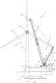
- Figures 1 and 2 show a side view and top view, respectively, of an example of a wind power station 1 that floats in open water, wherein a crane machine 10 has been arranged onto the wind power station 1.
- the wind power station 1 comprises a buoyant platform 2 provided with a wind turbine 33 extending upwards from the buoyant platform 2.
- the buoyant platform 2 is in this example a semi-submersible platform comprising first, second and third horizontally separated buoyant columns 3, 4, 5 connected by buoyant pontoons 21 and upper bracings 22 and provided with heave plates 3a, 4a, 5a.
- the wind turbine 33 is arranged on the third column 5 and comprises a turbine tower 6 and, arranged in an upper part of the tower 6, three blades 7 operatively connected to an electric generator 8 via a gearbox.
- the horizontal distance between the columns 3, 4, 5 is around 50 m and the height of the tower 6 is around 150 m.
- the first and second columns 3, 4 form first and second support points 13, 14 used when arranging the crane on the platform 2.
- the wind turbine 33 and the first and second support points form a triangle in the horizontal plane.
- the first support point 13, i.e. an upper side of the first column 3, is provided with a connection element (not shown in figures) configured to be connected to an undercarriage 17 for support of a rotatable crane base structure 11.
- the first and second support points 13, 14, i.e. the upper parts of the first and second columns 3, 4, are located horizontally spaced apart in relation to each other and at a substantially similar level above a surface of the open water (indicated by a wavy line in figure 1 ).
- the crane machine 10 comprises a rotatable crane base structure 11, a main boom 12, which in this case is telescopic, and hoist components, such as a hook 40, hoist wires, winches and motors for driving of winches, for lifting and lowering materials.
- hoist components such as a hook 40, hoist wires, winches and motors for driving of winches, for lifting and lowering materials.
- the crane machine 10 further comprises an undercarriage 17 onto which the rotatable crane base structure 11 is rotatably supported when the crane machine is assembled.
- the undercarriage 17 is secured to the first support point/first column 3 by means of the (not shown) connection element.
- a preinstalled connection element is not necessary but simplifies arrangement of the undercarriage 17.
- the crane machine 10 further comprises a derrick boom 25 configured to be connected via a lower end 25a thereof to the rotatable crane base structure 11 and extend upwards at an angle in relation to the main boom 12 so as to support the main boom 12 when arranging wires 27 between an upper part of the main boom 12 to the rotatable crane base structure 11 via an upper part 25b of the derrick boom.
- a derrick boom 25 configured to be connected via a lower end 25a thereof to the rotatable crane base structure 11 and extend upwards at an angle in relation to the main boom 12 so as to support the main boom 12 when arranging wires 27 between an upper part of the main boom 12 to the rotatable crane base structure 11 via an upper part 25b of the derrick boom.
- the crane machine 10 further comprises an additional boom or frame structure 16, in this example an additional temporary derrick-type boom that is shorter than the derrick boom 25 and used for forming a temporary crane machine 30 as described below.
- the additional boom or frame structure 16 is here configured to be connected via a lower end thereof 16a to the rotatable crane base structure 11 and extend upwards.
- the crane machine 10 further comprises a counter weight 15 configured to be connected to the rotatable crane base structure 11 via a connection arrangement 36 so as to be located at a distance from the rotatable crane base structure 11 in the horizontal direction.
- the connection arrangement 36 is hinged and provides for adjusting the horizontal position of the counter weight 15 in relation to the crane base structure 11.
- the counter weight 15 is in the form of a tank that can be filled with water, and the amount of water contained in the tank can be regulated.
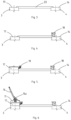
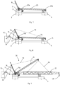
- FIG. 3-13 An example of how to arrange the crane machine 10 on the platform 2 is shown in figures 3-13 .
- the method comprises the steps of:
- the moving/lifting-step comprises:
- the amount of water in the counter weight tank 15 may also be regulated before, during or after certain method steps.
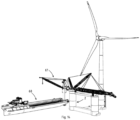
- Figure 4 shows an example of a floating wind power station and a vessel 60 carrying a dissembled crane machine where arranging of the crane machine onto the wind power station, i.e. onto the floating platform 2, is in progress.
- the vessel 60 is provided with a crane 61. Most parts of the dissembled crane machine are lifted and moved from the vessel 60 to the platform 2 using the vessel crane 61. However, the main boom is too large and heavy and has been lifted to the platform 2 using a temporary crane machine arranged onto the platform 2 as described in figure 8 .
- Figure 4 corresponds to the method step shown in figure 9 .
Landscapes
- Engineering & Computer Science (AREA)
- Mechanical Engineering (AREA)
- Transportation (AREA)
- Sustainable Energy (AREA)
- Life Sciences & Earth Sciences (AREA)
- Sustainable Development (AREA)
- Structural Engineering (AREA)
- Chemical & Material Sciences (AREA)
- Combustion & Propulsion (AREA)
- General Engineering & Computer Science (AREA)
- Jib Cranes (AREA)
- Wind Motors (AREA)
- Control And Safety Of Cranes (AREA)
Claims (15)
- Verfahren zum Anordnen einer Kranmaschine (10) an einer Windenergieanlage (1), die auf einem offenen Gewässer schwimmt, wobei die Windenergieanlage (1) eine schwimmfähige Plattform (2) umfasst, die mit einer Windturbine (33) bereitgestellt ist, die sich von der schwimmfähigen Plattform (2) empor erstreckt, wobei die schwimmfähige Plattform (2) mindestens einen ersten und einen zweiten Stützpunkt (3, 4, 13, 14) umfasst, die sich horizontal zueinander beabstandet und auf einer im Wesentlichen ähnlichen Ebene über einer Oberfläche des offenen Gewässers befinden,wobei die Kranmaschine (10) mindestens eine drehbare Kranbasisstruktur (11), einen Hauptausleger (12) und Hubkomponenten (40) zum Hochziehen und Absenken von Materialien umfasst,wobei die Kranmaschine (10), wenn sie an der Windenergieanlage (1) angeordnet ist, während der Hauptausleger (12) mit der drehbaren Kranbasisstruktur (11) verbunden ist und sich in einer Emporrichtung erstreckt und während die Hubkomponenten (40) installiert sind, dazu konfiguriert ist, schwere Windturbinenkomponenten (7, 8) zu/von einem oberen Teil der Windturbine (33) hochzuziehen/abzusenken,wobei das Verfahren die folgenden Schritte umfasst:- Bereitstellen der Kranmaschine (10) in einem mindestens teilweise zerlegten Zustand auf ein oder mehrere Schiffe (60) und Anordnen des einen oder der mehreren Schiffe (60) in Zuordnung zu der schwimmfähigen Plattform (2),- Verlegen/Hochziehen der mindestens teilweise zerlegten Kranmaschine (10) von dem einen oder den mehreren Schiffen (60) auf die schwimmfähige Plattform (2), wobei die drehbare Kranbasisstruktur (11) und der Hauptausleger (12) während des Verlegens/Hochziehens voneinander gelöst sind,- Zusammenbauen der Kranmaschine (10), wenn sie auf der schwimmfähigen Plattform (2) positioniert ist,wobei der Schritt des Verlegens/Hochziehens Folgendes umfasst:- Positionieren der drehbaren Kranbasisstruktur (11) an den ersten Stützpunkt (3, 13);- im Wesentlichen horizontales Positionieren des Hauptauslegers (13), wobei sich ein erster Endabschnitt (12a) an dem ersten Stützpunkt (3, 13) befindet, und- Positionieren des Hauptauslegers (12), um durch den zweiten Stützpunkt (4, 14) wie auch durch den ersten Stützpunkt (3, 13) und/oder einen weiteren Stützpunkt, der zwischen dem ersten und dem zweiten Stützpunkt (3, 13, 4, 14) angeordnet ist, abgestützt zu werden,wobei der Schritt des Zusammenbauens Folgendes umfasst:- Verbinden des ersten Endabschnitts (12a) des Hauptauslegers (12) mit der drehbaren Kranbasisstruktur (11), wenn der Hauptausleger (12) und die drehbare Kranbasisstruktur (11) auf der schwimmfähigen Plattform (2) positioniert sind.
- Verfahren nach Anspruch 1, wobei die Kranmaschine (10) ferner ein Fahrwerk (17) umfasst, auf das die drehbare Kranbasisstruktur (11) drehbar abgestützt wird, wenn die Kranmaschine (10) zusammengebaut wird, wobei das Verfahren Folgendes umfasst:- Positionieren und Sichern des Fahrwerks (17) an dem ersten Stützpunkt (3, 13) vor Positionieren der drehbaren Kranbasisstruktur (11) auf das Fahrwerk (17) an dem ersten Stützpunkt (3, 13).
- Verfahren nach Anspruch 1 oder 2, wobei die Kranmaschine (10) ferner einen Derrickausleger (25) umfasst, der dazu konfiguriert ist, über ein unteres Ende (25a) davon mit der drehbaren Kranbasisstruktur (11) verbunden zu sein und sich in einem Winkel in Bezug auf den Hauptausleger (12) empor zu erstrecken, um den Hauptausleger (12) beim Anordnen von Seilen (27) zwischen einem oberen Teil des Hauptauslegers (12) über einen oberen Teil (25b) des Derrickauslegers (25) auf die drehbare Kranbasisstruktur (11) abzustützen, wobei das Verfahren Folgendes umfasst:- Positionieren des Derrickauslegers (25) mit seinem unteren Ende (25a) an oder auf den ersten Stützpunkt (3, 13) und Verbinden des Derrickauslegers (25) mit der drehbaren Kranbasisstruktur (11).
- Verfahren nach Anspruch 3, wobei die Kranmaschine (10) ferner einen zusätzlichen Ausleger oder eine zusätzliche Gerüststruktur (16) umfasst, der/die kürzer als der Derrickausleger (25) ist, wobei der zusätzliche Ausleger oder die zusätzliche Gerüststruktur (16) über ein unteres Ende davon (16a) mit der drehbaren Kranbasisstruktur (11) verbunden oder dazu konfiguriert ist, mit ihr verbunden zu werden und sich empor zu erstrecken, wobei das Verfahren Folgendes umfasst:- Anordnen des zusätzlichen Auslegers oder der zusätzlichen Gerüststruktur (16) an der drehbaren Kranbasisstruktur (11), sodass das untere Ende (16a) des zusätzlichen Auslegers oder der zusätzlichen Gerüststruktur (16) mit der drehbaren Kranbasisstruktur (11) verbunden ist.
- Verfahren nach einem der vorhergehenden Ansprüche, wobei die Kranmaschine (10) ferner ein Gegengewicht (15) umfasst, das dazu konfiguriert ist, über eine Verbindungsanordnung (36) mit der drehbaren Kranbasisstruktur (11) verbunden zu werden, um sich in einem Abstand zu der drehbaren Kranbasisstruktur (11) in der horizontalen Richtung zu befinden, wobei das Verfahren Folgendes umfasst:- Verbinden des Gegengewichts (15) mit der drehbaren Kranbasisstruktur (11) über die Verbindungsanordnung (36).
- Verfahren nach Anspruch 3-5, wobei das Verfahren Folgendes umfasst:- Bilden einer vorübergehenden Kranmaschine (30), die den Derrickausleger (25), den zusätzlichen Ausleger oder die zusätzliche Gerüststruktur (16), das Gegengewicht (15) und die drehbare Kranbasisstruktur (11) umfasst, wobei der Derrickausleger (25) einen Hauptkranausleger für die vorübergehende Kranmaschine (30) bildet und wobei der zusätzliche Ausleger oder die zusätzliche Gerüststruktur (16) ein Derrickelement für den Hauptkranausleger der vorübergehenden Kranmaschine (30) bildet, und- Verlegen/Hochziehen des Hauptauslegers (12) von dem einen oder den mehreren Schiffen auf die schwimmfähige Plattform (2) unter Verwendung der vorübergehenden Kranmaschine (30).
- Verfahren nach Anspruch 3 und 5, wobei das Verfahren Folgendes umfasst:- Anheben des Hauptauslegers (12), um sich von der drehbaren Kranbasisstruktur (11) empor zu erstrecken, unter Verwendung des Derrickauslegers (25), des Gegengewichts (15) und der drehbaren Kranbasisstruktur (11).
- Verfahren nach Anspruch 5, wobei das Gegengewicht (15) einen Tank umfasst, der dazu konfiguriert ist, mit Wasser gefüllt zu werden, wobei das Verfahren Folgendes umfasst:- Regeln der Wassermenge in dem Gegengewichtstank (15).
- Verfahren nach einem der vorhergehenden Ansprüche, wobei die schwimmfähige Plattform (2) eine Halbtaucherplattform ist, die mindestens zwei horizontal getrennte schwimmfähige Säulen (3, 4, 5) umfasst, wobei die Säulen (3, 4, 5) den ersten und den zweiten Stützpunkt (13, 14) bilden.
- Verfahren nach einem der vorhergehenden Ansprüche, wobei der erste Stützpunkt (13) mit einem Verbindungselement bereitgestellt ist, das dazu konfiguriert ist, zur Abstützung der drehbaren Kranbasisstruktur (11) mit einem Fahrwerk (17) verbunden zu werden.
- Verfahren nach einem der vorhergehenden Ansprüche, wobei die Windturbine (33) einen Turm (6) und, in einem oberen Teil des Turmes (6) angeordnet, eine oder mehrere Laufschaufeln (7) umfasst, die betriebswirksam mit einem Elektrogenerator (8) verbunden sind.
- Verfahren nach einem der vorhergehenden Ansprüche, wobei die Windturbine (33) an einer schwimmfähigen Säule (5) angeordnet ist, die Teil der schwimmfähigen Plattform (2) ist.
- Verfahren nach einem der vorhergehenden Ansprüche, wobei sich der erste und der zweite Stützpunkt (13, 14) mindestens 30 m voneinander in einer horizontalen Richtung befinden.
- Verfahren nach einem der vorhergehenden Ansprüche, wobei sich jeder des ersten und des zweiten Stützpunkts (13, 14) in einem Abstand zu der Windturbine (33) in der horizontalen Richtung befindet, sodass die Windturbine (33) und der erste und der zweite Stützpunkt (13, 14) ein Dreieck auf der horizontalen Ebene bilden.
- Windenergieanlage (1), umfassend eine schwimmfähige Plattform (2), die mit einer Windturbine (33) bereitgestellt ist, die sich von der schwimmfähigen Plattform (2) empor erstreckt,wobei die schwimmfähige Plattform (2) mindestens einen ersten und einen zweiten Stützpunkt (3, 4, 13, 14) umfasst, die sich horizontal zueinander beabstandet und auf einer im Wesentlichen ähnlichen Ebene über einer Oberfläche eines offenen Gewässers befinden, auf der die Windenergieanlage (1) schwimmt,wobei die Windenergieanlage (1) eine Kranmaschine (10) umfasst, die mindestens eine drehbare Kranbasisstruktur (11), einen Hauptausleger (12) und Hubkomponenten (40) zum Hochziehen und Absenken von Materialien umfasst,wobei die Kranmaschine (10), wenn sie an der Windenergieanlage (1) angeordnet ist, während der Hauptausleger (12) mit der drehbaren Kranbasisstruktur (11) verbunden ist und sich in einer Emporrichtung erstreckt und während die Hubkomponenten (40) installiert sind, dazu konfiguriert ist, schwere Windturbinenkomponenten (7, 8) zu/von einem oberen Teil der Windturbine (33) hochzuziehen/abzusenken,wobei der erste Stützpunkt (3, 13) mit einem Verbindungselement bereitgestellt ist, das dazu konfiguriert ist, zur Abstützung der drehbaren Kranbasisstruktur (11) mit einem Fahrwerk (17) verbunden zu werden.
Applications Claiming Priority (2)
| Application Number | Priority Date | Filing Date | Title |
|---|---|---|---|
| SE2151104A SE545505C2 (en) | 2021-09-03 | 2021-09-03 | Method for arranging a crane machine on a wind power station |
| PCT/EP2022/074387 WO2023031360A1 (en) | 2021-09-03 | 2022-09-01 | Arrangement of a crane on a floating wind power station |
Publications (3)
| Publication Number | Publication Date |
|---|---|
| EP4298046A1 EP4298046A1 (de) | 2024-01-03 |
| EP4298046C0 EP4298046C0 (de) | 2024-08-14 |
| EP4298046B1 true EP4298046B1 (de) | 2024-08-14 |
Family
ID=83355086
Family Applications (1)
| Application Number | Title | Priority Date | Filing Date |
|---|---|---|---|
| EP22772510.8A Active EP4298046B1 (de) | 2021-09-03 | 2022-09-01 | Anordnung eines krans an einer schwimmenden windenergieanlage |
Country Status (4)
| Country | Link |
|---|---|
| EP (1) | EP4298046B1 (de) |
| CN (1) | CN118679117A (de) |
| SE (1) | SE545505C2 (de) |
| WO (1) | WO2023031360A1 (de) |
Families Citing this family (1)
| Publication number | Priority date | Publication date | Assignee | Title |
|---|---|---|---|---|
| NL2034923B1 (en) * | 2023-05-26 | 2024-12-05 | Itrec Bv | Crane with luffable boom |
Citations (1)
| Publication number | Priority date | Publication date | Assignee | Title |
|---|---|---|---|---|
| WO2020167137A1 (en) * | 2019-02-12 | 2020-08-20 | Aker Solutions As | Wind energy power plant and method of construction |
Family Cites Families (6)
| Publication number | Priority date | Publication date | Assignee | Title |
|---|---|---|---|---|
| GB2142312B (en) * | 1983-06-29 | 1986-06-18 | Fmc Corp | Modularised pedestal mount crane and method of disassembly |
| US4582205A (en) * | 1983-06-29 | 1986-04-15 | Fmc Corporation | Modularized pedestal-mount crane and method of disassembly |
| WO2007009464A1 (en) * | 2005-07-19 | 2007-01-25 | Pp Energy Aps | Plant for exploiting wind energy at sea |
| EP2275340B1 (de) * | 2009-05-22 | 2017-10-11 | Keppel Fels Ltd | Offshore-Windturbineninstallation |
| EP3515851B1 (de) * | 2016-09-19 | 2023-06-07 | GustoMSC B.V. | Ausziehbarer ausleger mit verriegelungssystem und verfahren zum betrieb eines ausziehbaren auslegers eines krans |
| DK4088023T3 (da) * | 2020-01-07 | 2024-04-29 | Seatrium Sg Pte Ltd | Indretning og fremgangsmåde til justering af et vindmøllesystem, og mast af et vindmøllesystem |
-
2021
- 2021-09-03 SE SE2151104A patent/SE545505C2/en unknown
-
2022
- 2022-09-01 EP EP22772510.8A patent/EP4298046B1/de active Active
- 2022-09-01 CN CN202280059712.3A patent/CN118679117A/zh active Pending
- 2022-09-01 WO PCT/EP2022/074387 patent/WO2023031360A1/en not_active Ceased
Patent Citations (1)
| Publication number | Priority date | Publication date | Assignee | Title |
|---|---|---|---|---|
| WO2020167137A1 (en) * | 2019-02-12 | 2020-08-20 | Aker Solutions As | Wind energy power plant and method of construction |
Also Published As
| Publication number | Publication date |
|---|---|
| CN118679117A (zh) | 2024-09-20 |
| WO2023031360A1 (en) | 2023-03-09 |
| SE2151104A1 (en) | 2023-03-04 |
| EP4298046C0 (de) | 2024-08-14 |
| SE545505C2 (en) | 2023-10-03 |
| EP4298046A1 (de) | 2024-01-03 |
Similar Documents
| Publication | Publication Date | Title |
|---|---|---|
| US11970370B2 (en) | Motion compensating crane for use on an offshore vessel | |
| EP2231469B1 (de) | Verfahren zur installation einer offshore-windturbine und kahnsystem | |
| EP1101935B1 (de) | Methode und schiff zur installation von windkraftanlagen auf see | |
| US10941023B2 (en) | Wave-induced motion compensating crane for use on an offshore vessel, vessel and load transferring method | |
| EP2585712B1 (de) | Hebevorrichtung und verfahren zum positionieren eines sperrigen objects | |
| US20230392584A1 (en) | Installation of a wind turbine on a floating foundation | |
| US20140212288A1 (en) | High capacity elevator for wind turbine maintenance | |
| KR101401985B1 (ko) | 수상구조물 설치용 잭업식 플로팅 크레인 | |
| KR20130059397A (ko) | 부체 구조물 작업 시스템, 부체 구조물, 작업선 및 부체 구조물 작업 방법 | |
| US12187585B2 (en) | Crane vessel for hoisting of an offshore wind turbine or component thereof | |
| WO2009041812A1 (en) | Method and structure for lifting and attaching a composite structure to a vertical support | |
| US20120027523A1 (en) | Device and method for assembling a structure at sea | |
| EP4402365B1 (de) | Installation und/oder entfernung einer windturbinenkomponente für eine schwimmende fundamentwindturbine | |
| US20230399206A1 (en) | Offshore wind turbine assembly vessel | |
| EP2256079B1 (de) | Vorrichtung und Verfahren zur Montage einer Struktur auf See | |
| US20240217782A1 (en) | Upend crane and installation vessel | |
| US20240301869A1 (en) | Offshore wind turbine assembly vessel | |
| EP4298046B1 (de) | Anordnung eines krans an einer schwimmenden windenergieanlage | |
| WO2010120186A1 (en) | Floating windmill and method of installation, intervention or decommissioning | |
| NL2028741B1 (en) | upend crane and installation vessel | |
| JP2025166523A (ja) | 浮体式洋上風力発電施設の施工方法 | |
| CN117769524A (zh) | 竖立起重机和安装船舶 | |
| CN116648421A (zh) | 海上风力涡轮机组装船舶 |
Legal Events
| Date | Code | Title | Description |
|---|---|---|---|
| STAA | Information on the status of an ep patent application or granted ep patent |
Free format text: STATUS: UNKNOWN |
|
| STAA | Information on the status of an ep patent application or granted ep patent |
Free format text: STATUS: THE INTERNATIONAL PUBLICATION HAS BEEN MADE |
|
| PUAI | Public reference made under article 153(3) epc to a published international application that has entered the european phase |
Free format text: ORIGINAL CODE: 0009012 |
|
| STAA | Information on the status of an ep patent application or granted ep patent |
Free format text: STATUS: REQUEST FOR EXAMINATION WAS MADE |
|
| 17P | Request for examination filed |
Effective date: 20230929 |
|
| AK | Designated contracting states |
Kind code of ref document: A1 Designated state(s): AL AT BE BG CH CY CZ DE DK EE ES FI FR GB GR HR HU IE IS IT LI LT LU LV MC MK MT NL NO PL PT RO RS SE SI SK SM TR |
|
| TPAC | Observations filed by third parties |
Free format text: ORIGINAL CODE: EPIDOSNTIPA |
|
| GRAP | Despatch of communication of intention to grant a patent |
Free format text: ORIGINAL CODE: EPIDOSNIGR1 |
|
| STAA | Information on the status of an ep patent application or granted ep patent |
Free format text: STATUS: GRANT OF PATENT IS INTENDED |
|
| INTG | Intention to grant announced |
Effective date: 20240422 |
|
| GRAS | Grant fee paid |
Free format text: ORIGINAL CODE: EPIDOSNIGR3 |
|
| GRAA | (expected) grant |
Free format text: ORIGINAL CODE: 0009210 |
|
| STAA | Information on the status of an ep patent application or granted ep patent |
Free format text: STATUS: THE PATENT HAS BEEN GRANTED |
|
| AK | Designated contracting states |
Kind code of ref document: B1 Designated state(s): AL AT BE BG CH CY CZ DE DK EE ES FI FR GB GR HR HU IE IS IT LI LT LU LV MC MK MT NL NO PL PT RO RS SE SI SK SM TR |
|
| DAV | Request for validation of the european patent (deleted) | ||
| DAX | Request for extension of the european patent (deleted) | ||
| REG | Reference to a national code |
Ref country code: GB Ref legal event code: FG4D |
|
| REG | Reference to a national code |
Ref country code: CH Ref legal event code: EP |
|
| REG | Reference to a national code |
Ref country code: DE Ref legal event code: R096 Ref document number: 602022005361 Country of ref document: DE |
|
| REG | Reference to a national code |
Ref country code: IE Ref legal event code: FG4D |
|
| U01 | Request for unitary effect filed |
Effective date: 20240906 |
|
| U07 | Unitary effect registered |
Designated state(s): AT BE BG DE DK EE FI FR IT LT LU LV MT NL PT RO SE SI Effective date: 20240923 |
|
| U20 | Renewal fee for the european patent with unitary effect paid |
Year of fee payment: 3 Effective date: 20241003 |
|
| PG25 | Lapsed in a contracting state [announced via postgrant information from national office to epo] |
Ref country code: GR Free format text: LAPSE BECAUSE OF FAILURE TO SUBMIT A TRANSLATION OF THE DESCRIPTION OR TO PAY THE FEE WITHIN THE PRESCRIBED TIME-LIMIT Effective date: 20241115 Ref country code: PL Free format text: LAPSE BECAUSE OF FAILURE TO SUBMIT A TRANSLATION OF THE DESCRIPTION OR TO PAY THE FEE WITHIN THE PRESCRIBED TIME-LIMIT Effective date: 20240814 |
|
| PG25 | Lapsed in a contracting state [announced via postgrant information from national office to epo] |
Ref country code: IS Free format text: LAPSE BECAUSE OF FAILURE TO SUBMIT A TRANSLATION OF THE DESCRIPTION OR TO PAY THE FEE WITHIN THE PRESCRIBED TIME-LIMIT Effective date: 20241214 |
|
| PG25 | Lapsed in a contracting state [announced via postgrant information from national office to epo] |
Ref country code: HR Free format text: LAPSE BECAUSE OF FAILURE TO SUBMIT A TRANSLATION OF THE DESCRIPTION OR TO PAY THE FEE WITHIN THE PRESCRIBED TIME-LIMIT Effective date: 20240814 |
|
| PG25 | Lapsed in a contracting state [announced via postgrant information from national office to epo] |
Ref country code: RS Free format text: LAPSE BECAUSE OF FAILURE TO SUBMIT A TRANSLATION OF THE DESCRIPTION OR TO PAY THE FEE WITHIN THE PRESCRIBED TIME-LIMIT Effective date: 20241114 Ref country code: ES Free format text: LAPSE BECAUSE OF FAILURE TO SUBMIT A TRANSLATION OF THE DESCRIPTION OR TO PAY THE FEE WITHIN THE PRESCRIBED TIME-LIMIT Effective date: 20240814 |
|
| PG25 | Lapsed in a contracting state [announced via postgrant information from national office to epo] |
Ref country code: RS Free format text: LAPSE BECAUSE OF FAILURE TO SUBMIT A TRANSLATION OF THE DESCRIPTION OR TO PAY THE FEE WITHIN THE PRESCRIBED TIME-LIMIT Effective date: 20241114 Ref country code: PL Free format text: LAPSE BECAUSE OF FAILURE TO SUBMIT A TRANSLATION OF THE DESCRIPTION OR TO PAY THE FEE WITHIN THE PRESCRIBED TIME-LIMIT Effective date: 20240814 Ref country code: IS Free format text: LAPSE BECAUSE OF FAILURE TO SUBMIT A TRANSLATION OF THE DESCRIPTION OR TO PAY THE FEE WITHIN THE PRESCRIBED TIME-LIMIT Effective date: 20241214 Ref country code: HR Free format text: LAPSE BECAUSE OF FAILURE TO SUBMIT A TRANSLATION OF THE DESCRIPTION OR TO PAY THE FEE WITHIN THE PRESCRIBED TIME-LIMIT Effective date: 20240814 Ref country code: GR Free format text: LAPSE BECAUSE OF FAILURE TO SUBMIT A TRANSLATION OF THE DESCRIPTION OR TO PAY THE FEE WITHIN THE PRESCRIBED TIME-LIMIT Effective date: 20241115 Ref country code: ES Free format text: LAPSE BECAUSE OF FAILURE TO SUBMIT A TRANSLATION OF THE DESCRIPTION OR TO PAY THE FEE WITHIN THE PRESCRIBED TIME-LIMIT Effective date: 20240814 |
|
| PG25 | Lapsed in a contracting state [announced via postgrant information from national office to epo] |
Ref country code: SM Free format text: LAPSE BECAUSE OF FAILURE TO SUBMIT A TRANSLATION OF THE DESCRIPTION OR TO PAY THE FEE WITHIN THE PRESCRIBED TIME-LIMIT Effective date: 20240814 |
|
| PG25 | Lapsed in a contracting state [announced via postgrant information from national office to epo] |
Ref country code: CZ Free format text: LAPSE BECAUSE OF FAILURE TO SUBMIT A TRANSLATION OF THE DESCRIPTION OR TO PAY THE FEE WITHIN THE PRESCRIBED TIME-LIMIT Effective date: 20240814 |
|
| PG25 | Lapsed in a contracting state [announced via postgrant information from national office to epo] |
Ref country code: SK Free format text: LAPSE BECAUSE OF FAILURE TO SUBMIT A TRANSLATION OF THE DESCRIPTION OR TO PAY THE FEE WITHIN THE PRESCRIBED TIME-LIMIT Effective date: 20240814 |
|
| PLBE | No opposition filed within time limit |
Free format text: ORIGINAL CODE: 0009261 |
|
| STAA | Information on the status of an ep patent application or granted ep patent |
Free format text: STATUS: NO OPPOSITION FILED WITHIN TIME LIMIT |
|
| PG25 | Lapsed in a contracting state [announced via postgrant information from national office to epo] |
Ref country code: MC Free format text: LAPSE BECAUSE OF FAILURE TO SUBMIT A TRANSLATION OF THE DESCRIPTION OR TO PAY THE FEE WITHIN THE PRESCRIBED TIME-LIMIT Effective date: 20240814 |
|
| 26N | No opposition filed |
Effective date: 20250515 |
|
| PG25 | Lapsed in a contracting state [announced via postgrant information from national office to epo] |
Ref country code: IE Free format text: LAPSE BECAUSE OF NON-PAYMENT OF DUE FEES Effective date: 20240901 |
|
| U20 | Renewal fee for the european patent with unitary effect paid |
Year of fee payment: 4 Effective date: 20250721 |
|
| PGFP | Annual fee paid to national office [announced via postgrant information from national office to epo] |
Ref country code: NO Payment date: 20250828 Year of fee payment: 4 |