EP4297960B1 - Verfahren zur herstellung eines verbundteils und vorform zur herstellung davon - Google Patents
Verfahren zur herstellung eines verbundteils und vorform zur herstellung davon Download PDFInfo
- Publication number
- EP4297960B1 EP4297960B1 EP22707101.6A EP22707101A EP4297960B1 EP 4297960 B1 EP4297960 B1 EP 4297960B1 EP 22707101 A EP22707101 A EP 22707101A EP 4297960 B1 EP4297960 B1 EP 4297960B1
- Authority
- EP
- European Patent Office
- Prior art keywords
- discrete
- impregnated
- segmented
- continuous
- layer
- Prior art date
- Legal status (The legal status is an assumption and is not a legal conclusion. Google has not performed a legal analysis and makes no representation as to the accuracy of the status listed.)
- Active
Links
Images


Classifications
-
- B—PERFORMING OPERATIONS; TRANSPORTING
- B29—WORKING OF PLASTICS; WORKING OF SUBSTANCES IN A PLASTIC STATE IN GENERAL
- B29C—SHAPING OR JOINING OF PLASTICS; SHAPING OF MATERIAL IN A PLASTIC STATE, NOT OTHERWISE PROVIDED FOR; AFTER-TREATMENT OF THE SHAPED PRODUCTS, e.g. REPAIRING
- B29C70/00—Shaping composites, i.e. plastics material comprising reinforcements, fillers or preformed parts, e.g. inserts
- B29C70/04—Shaping composites, i.e. plastics material comprising reinforcements, fillers or preformed parts, e.g. inserts comprising reinforcements only, e.g. self-reinforcing plastics
- B29C70/06—Fibrous reinforcements only
- B29C70/10—Fibrous reinforcements only characterised by the structure of fibrous reinforcements, e.g. hollow fibres
- B29C70/16—Fibrous reinforcements only characterised by the structure of fibrous reinforcements, e.g. hollow fibres using fibres of substantial or continuous length
- B29C70/22—Fibrous reinforcements only characterised by the structure of fibrous reinforcements, e.g. hollow fibres using fibres of substantial or continuous length oriented in at least two directions forming a two dimensional structure
- B29C70/228—Fibrous reinforcements only characterised by the structure of fibrous reinforcements, e.g. hollow fibres using fibres of substantial or continuous length oriented in at least two directions forming a two dimensional structure the structure being stacked in parallel layers with fibres of adjacent layers crossing at substantial angles
-
- B—PERFORMING OPERATIONS; TRANSPORTING
- B29—WORKING OF PLASTICS; WORKING OF SUBSTANCES IN A PLASTIC STATE IN GENERAL
- B29B—PREPARATION OR PRETREATMENT OF THE MATERIAL TO BE SHAPED; MAKING GRANULES OR PREFORMS; RECOVERY OF PLASTICS OR OTHER CONSTITUENTS OF WASTE MATERIAL CONTAINING PLASTICS
- B29B11/00—Making preforms
- B29B11/14—Making preforms characterised by structure or composition
- B29B11/16—Making preforms characterised by structure or composition comprising fillers or reinforcement
-
- B—PERFORMING OPERATIONS; TRANSPORTING
- B29—WORKING OF PLASTICS; WORKING OF SUBSTANCES IN A PLASTIC STATE IN GENERAL
- B29C—SHAPING OR JOINING OF PLASTICS; SHAPING OF MATERIAL IN A PLASTIC STATE, NOT OTHERWISE PROVIDED FOR; AFTER-TREATMENT OF THE SHAPED PRODUCTS, e.g. REPAIRING
- B29C70/00—Shaping composites, i.e. plastics material comprising reinforcements, fillers or preformed parts, e.g. inserts
- B29C70/04—Shaping composites, i.e. plastics material comprising reinforcements, fillers or preformed parts, e.g. inserts comprising reinforcements only, e.g. self-reinforcing plastics
- B29C70/06—Fibrous reinforcements only
- B29C70/10—Fibrous reinforcements only characterised by the structure of fibrous reinforcements, e.g. hollow fibres
- B29C70/16—Fibrous reinforcements only characterised by the structure of fibrous reinforcements, e.g. hollow fibres using fibres of substantial or continuous length
- B29C70/20—Fibrous reinforcements only characterised by the structure of fibrous reinforcements, e.g. hollow fibres using fibres of substantial or continuous length oriented in a single direction, e.g. roofing or other parallel fibres
- B29C70/205—Fibrous reinforcements only characterised by the structure of fibrous reinforcements, e.g. hollow fibres using fibres of substantial or continuous length oriented in a single direction, e.g. roofing or other parallel fibres the structure being shaped to form a three-dimensional configuration
- B29C70/207—Fibrous reinforcements only characterised by the structure of fibrous reinforcements, e.g. hollow fibres using fibres of substantial or continuous length oriented in a single direction, e.g. roofing or other parallel fibres the structure being shaped to form a three-dimensional configuration arranged in parallel planes of fibres crossing at substantial angles
-
- B—PERFORMING OPERATIONS; TRANSPORTING
- B29—WORKING OF PLASTICS; WORKING OF SUBSTANCES IN A PLASTIC STATE IN GENERAL
- B29C—SHAPING OR JOINING OF PLASTICS; SHAPING OF MATERIAL IN A PLASTIC STATE, NOT OTHERWISE PROVIDED FOR; AFTER-TREATMENT OF THE SHAPED PRODUCTS, e.g. REPAIRING
- B29C70/00—Shaping composites, i.e. plastics material comprising reinforcements, fillers or preformed parts, e.g. inserts
- B29C70/04—Shaping composites, i.e. plastics material comprising reinforcements, fillers or preformed parts, e.g. inserts comprising reinforcements only, e.g. self-reinforcing plastics
- B29C70/28—Shaping operations therefor
- B29C70/30—Shaping by lay-up, i.e. applying fibres, tape or broadsheet on a mould, former or core; Shaping by spray-up, i.e. spraying of fibres on a mould, former or core
-
- B—PERFORMING OPERATIONS; TRANSPORTING
- B29—WORKING OF PLASTICS; WORKING OF SUBSTANCES IN A PLASTIC STATE IN GENERAL
- B29C—SHAPING OR JOINING OF PLASTICS; SHAPING OF MATERIAL IN A PLASTIC STATE, NOT OTHERWISE PROVIDED FOR; AFTER-TREATMENT OF THE SHAPED PRODUCTS, e.g. REPAIRING
- B29C70/00—Shaping composites, i.e. plastics material comprising reinforcements, fillers or preformed parts, e.g. inserts
- B29C70/04—Shaping composites, i.e. plastics material comprising reinforcements, fillers or preformed parts, e.g. inserts comprising reinforcements only, e.g. self-reinforcing plastics
- B29C70/28—Shaping operations therefor
- B29C70/40—Shaping or impregnating by compression not applied
- B29C70/50—Shaping or impregnating by compression not applied for producing articles of indefinite length, e.g. prepregs, sheet moulding compounds [SMC] or cross moulding compounds [XMC]
-
- B—PERFORMING OPERATIONS; TRANSPORTING
- B29—WORKING OF PLASTICS; WORKING OF SUBSTANCES IN A PLASTIC STATE IN GENERAL
- B29C—SHAPING OR JOINING OF PLASTICS; SHAPING OF MATERIAL IN A PLASTIC STATE, NOT OTHERWISE PROVIDED FOR; AFTER-TREATMENT OF THE SHAPED PRODUCTS, e.g. REPAIRING
- B29C70/00—Shaping composites, i.e. plastics material comprising reinforcements, fillers or preformed parts, e.g. inserts
- B29C70/04—Shaping composites, i.e. plastics material comprising reinforcements, fillers or preformed parts, e.g. inserts comprising reinforcements only, e.g. self-reinforcing plastics
- B29C70/28—Shaping operations therefor
- B29C70/54—Component parts, details or accessories; Auxiliary operations, e.g. feeding or storage of prepregs or SMC after impregnation or during ageing
- B29C70/545—Perforating, cutting or machining during or after moulding
-
- B—PERFORMING OPERATIONS; TRANSPORTING
- B32—LAYERED PRODUCTS
- B32B—LAYERED PRODUCTS, i.e. PRODUCTS BUILT-UP OF STRATA OF FLAT OR NON-FLAT, e.g. CELLULAR OR HONEYCOMB, FORM
- B32B5/00—Layered products characterised by the non- homogeneity or physical structure, i.e. comprising a fibrous, filamentary, particulate or foam layer; Layered products characterised by having a layer differing constitutionally or physically in different parts
- B32B5/02—Layered products characterised by the non- homogeneity or physical structure, i.e. comprising a fibrous, filamentary, particulate or foam layer; Layered products characterised by having a layer differing constitutionally or physically in different parts characterised by structural features of a fibrous or filamentary layer
- B32B5/12—Layered products characterised by the non- homogeneity or physical structure, i.e. comprising a fibrous, filamentary, particulate or foam layer; Layered products characterised by having a layer differing constitutionally or physically in different parts characterised by structural features of a fibrous or filamentary layer characterised by the relative arrangement of fibres or filaments of different layers, e.g. the fibres or filaments being parallel or perpendicular to each other
-
- B—PERFORMING OPERATIONS; TRANSPORTING
- B32—LAYERED PRODUCTS
- B32B—LAYERED PRODUCTS, i.e. PRODUCTS BUILT-UP OF STRATA OF FLAT OR NON-FLAT, e.g. CELLULAR OR HONEYCOMB, FORM
- B32B5/00—Layered products characterised by the non- homogeneity or physical structure, i.e. comprising a fibrous, filamentary, particulate or foam layer; Layered products characterised by having a layer differing constitutionally or physically in different parts
- B32B5/22—Layered products characterised by the non- homogeneity or physical structure, i.e. comprising a fibrous, filamentary, particulate or foam layer; Layered products characterised by having a layer differing constitutionally or physically in different parts characterised by the presence of two or more layers which are next to each other and are fibrous, filamentary, formed of particles or foamed
- B32B5/24—Layered products characterised by the non- homogeneity or physical structure, i.e. comprising a fibrous, filamentary, particulate or foam layer; Layered products characterised by having a layer differing constitutionally or physically in different parts characterised by the presence of two or more layers which are next to each other and are fibrous, filamentary, formed of particles or foamed one layer being a fibrous or filamentary layer
- B32B5/28—Layered products characterised by the non- homogeneity or physical structure, i.e. comprising a fibrous, filamentary, particulate or foam layer; Layered products characterised by having a layer differing constitutionally or physically in different parts characterised by the presence of two or more layers which are next to each other and are fibrous, filamentary, formed of particles or foamed one layer being a fibrous or filamentary layer impregnated with or embedded in a plastic substance
-
- B—PERFORMING OPERATIONS; TRANSPORTING
- B29—WORKING OF PLASTICS; WORKING OF SUBSTANCES IN A PLASTIC STATE IN GENERAL
- B29C—SHAPING OR JOINING OF PLASTICS; SHAPING OF MATERIAL IN A PLASTIC STATE, NOT OTHERWISE PROVIDED FOR; AFTER-TREATMENT OF THE SHAPED PRODUCTS, e.g. REPAIRING
- B29C70/00—Shaping composites, i.e. plastics material comprising reinforcements, fillers or preformed parts, e.g. inserts
- B29C70/04—Shaping composites, i.e. plastics material comprising reinforcements, fillers or preformed parts, e.g. inserts comprising reinforcements only, e.g. self-reinforcing plastics
- B29C70/28—Shaping operations therefor
- B29C70/30—Shaping by lay-up, i.e. applying fibres, tape or broadsheet on a mould, former or core; Shaping by spray-up, i.e. spraying of fibres on a mould, former or core
- B29C70/38—Automated lay-up, e.g. using robots, laying filaments according to predetermined patterns
- B29C70/386—Automated tape laying [ATL]
-
- B—PERFORMING OPERATIONS; TRANSPORTING
- B29—WORKING OF PLASTICS; WORKING OF SUBSTANCES IN A PLASTIC STATE IN GENERAL
- B29K—INDEXING SCHEME ASSOCIATED WITH SUBCLASSES B29B, B29C OR B29D, RELATING TO MOULDING MATERIALS OR TO MATERIALS FOR MOULDS, REINFORCEMENTS, FILLERS OR PREFORMED PARTS, e.g. INSERTS
- B29K2105/00—Condition, form or state of moulded material or of the material to be shaped
- B29K2105/06—Condition, form or state of moulded material or of the material to be shaped containing reinforcements, fillers or inserts
- B29K2105/08—Condition, form or state of moulded material or of the material to be shaped containing reinforcements, fillers or inserts of continuous length, e.g. cords, rovings, mats, fabrics, strands or yarns
- B29K2105/0872—Prepregs
- B29K2105/0881—Prepregs unidirectional
-
- Y—GENERAL TAGGING OF NEW TECHNOLOGICAL DEVELOPMENTS; GENERAL TAGGING OF CROSS-SECTIONAL TECHNOLOGIES SPANNING OVER SEVERAL SECTIONS OF THE IPC; TECHNICAL SUBJECTS COVERED BY FORMER USPC CROSS-REFERENCE ART COLLECTIONS [XRACs] AND DIGESTS
- Y10—TECHNICAL SUBJECTS COVERED BY FORMER USPC
- Y10T—TECHNICAL SUBJECTS COVERED BY FORMER US CLASSIFICATION
- Y10T428/00—Stock material or miscellaneous articles
- Y10T428/16—Two dimensionally sectional layer
- Y10T428/163—Next to unitary web or sheet of equal or greater extent
-
- Y—GENERAL TAGGING OF NEW TECHNOLOGICAL DEVELOPMENTS; GENERAL TAGGING OF CROSS-SECTIONAL TECHNOLOGIES SPANNING OVER SEVERAL SECTIONS OF THE IPC; TECHNICAL SUBJECTS COVERED BY FORMER USPC CROSS-REFERENCE ART COLLECTIONS [XRACs] AND DIGESTS
- Y10—TECHNICAL SUBJECTS COVERED BY FORMER USPC
- Y10T—TECHNICAL SUBJECTS COVERED BY FORMER US CLASSIFICATION
- Y10T428/00—Stock material or miscellaneous articles
- Y10T428/18—Longitudinally sectional layer of three or more sections
- Y10T428/183—Next to unitary sheet of equal or greater extent
- Y10T428/187—Continuous sectional layer
Definitions
- the invention relates to the field of high-performance composite parts.
- the invention relates more particularly to a semi-finished composite product based on segments of long fibers embedded in a resin matrix.
- Composite materials are increasingly present in sectors where we find moving parts.
- the most concerned sectors are for example aeronautics, space, medical, automotive and mobility in general because these materials allow to produce parts with performances equivalent to the usual metal parts but with lower masses.
- the density of titanium is 4.40 kg/dm 3
- that of aluminum is 2.70 kg/dm 3
- that of epoxy carbon is 1.60 kg/dm 3 .
- This optimization of mass allows, for example, aircraft manufacturers to lighten aircraft structures and therefore reduce the power of the engines on board said aircraft.
- This provision allows airlines to reduce fuel consumption, reduce their carbon footprint and increase the number of passengers as well as the ranges of aircraft. All of these advantages make it possible to reduce flight costs per passenger.
- New aircraft incorporate composite materials for more than 50% of their mass. These composite materials are composed partly of a network of generally woven or unidirectional fibers and partly of resin, usually thermosetting or thermoplastic.
- Reinforcing fibers typically carbon or glass fibers, but also aramid or natural (e.g., vegetable), have high orthotropic properties in the length direction.
- a stress applied to the part is transmitted by the resin to the fibers through the interface between the fibers and the resins.
- the longer the fibers the longer and more effective the interface through which the transmission of a stress can take place between the resin and a fiber.
- a distinction is thus made between high-performance long-fiber composites and lower-performance short-fiber composites.
- long fibers are referred to as fibers with a length of at least 2 mm, because beyond these lengths it becomes very difficult or even impossible to injection mold such a composite.
- long fibers are defined as fibers having a length of at least 10 mm, preferably at least 50 mm or even at least 100 mm.
- Continuous fibers are of course considered long fibers. This criterion is chosen not with respect to the possibility or not of injection molding, but rather on the basis of a matrix-fiber interface length sufficient to obtain sufficient load transfer from the matrix to the fibers when a composite part is subjected to external stresses.
- Short-fiber composites therefore have lower mechanical properties than long-fiber composites, but allow the manufacture of parts with complex geometries, for example by injection molding.
- long-fiber composites oriented in a targeted manner in order to take advantage of the orthotropic properties of the fibers offer very high performance, they generally do not allow the manufacture of parts with complex geometries. It has been a long-standing objective in the field of composite materials to be able to increase the complexity of the geometry of parts while maintaining high mechanical properties specific to long-fiber composites.
- the present invention provides a solution to this historical and still current problem.
- the document US 2010/0233423 A1 describes the production of a molding material that has cuts made transversely to an extension direction defined by the direction of the fiber reinforcement chain on the textile reinforcement.
- This document describes partial cuts and therefore do not allow the fiber bundles to be completely separated from each other.
- This document also does not describe the cutting of the resin system and in the case where these partial cuts allow the textile to be deformed in the direction of the chain, they do not allow the segments to be preserved in their entirety during their relative movement.
- the unit segment can move without causing tearing or curling of the fiber reinforcements and this without involving separation between the fibers and the resin.
- the solutions to the technical problems mentioned above are not mentioned.
- the cuts in the direction of the chain are geometrically aligned, which causes a path of weakness on the final part. Said path of weakness is detrimental to the final mechanical characteristics of the part.
- High-performance SMC Sheet Molding Compound
- BMC Bulk Molding Compound
- Many BMC or SMC type molding products allow for cost optimization because they reduce production times, however, due to their uncontrolled and non-repetitive fiber organization, these types of moldings are difficult to apply to parts subject to high mechanical stresses.
- the SMC type allows for greater industrialization, but without achieving the performance or reproducibility of manual processes applicable to pre-impregnated composite materials.
- the technical problem with the SMC type lies in the fact that the reinforcing fibers are cut while they are still dry and unimpregnated, then distributed by gravity on a resin film. This distribution being random, the final fiber volume fraction of the composite varies significantly. The random distribution also gives uncontrolled and non-reproducible fiber directions, making these materials difficult to use for applications where mechanical constraints are significant.
- the document US 6,838,148 B1 describes an improved SMC material consisting of a stack of pre-impregnated unidirectional fibers and randomly distributed chopped fibers. The fibers are superimposed in successive layers, each having a different direction. While this product may represent an advance over a traditional SMC, it does not address two major technical issues, the first being the material's ability to deform in order to meet the different shape constraints of a wide variety of parts and the second being its relatively poor mechanical properties due to the random distribution of the fibers.
- EP1134314 A1 describes a composite intermediate product that is in the form of layers of pre-impregnated fiber segments. These segments are randomly arranged in the plane (2 Dimensions), however, even if their average distribution is almost isotropic, their precise distribution in the plane is random and there is significant embuvage between the bundles, therefore, their mechanical characteristics will be low and cannot be finely controlled nor give rise to the production of parts with reproducible characteristics.
- EP 3140104 A1 describes the production of a preform using narrow strips using an automatic carbon strip depositing machine.
- a major problem with using such a machine is the cost associated with its purchase, which remains difficult to amortize.
- This document does not address the possibility of producing a standard SMC-type base material with this machine.
- a reinforcement angle ( ⁇ ) is defined here in this document with a tolerance of ⁇ 5°.
- the invention therefore aims to propose a method for manufacturing high-performance composite parts with complex geometries, using an innovative discrete segmented multilayer mat obtained from discrete segmented plies that can use as starting material directly and without prior handling pre-impregnated single-layer sheets available on the market or from offcuts from another process for large-sized composite parts.
- the present invention also relates to methods for manufacturing discrete pre-impregnated plies and discrete segmented multilayer mats.
- a continuous sheet is defined as a sheet having a geometry inscribed in a rectangle of length (L) and width (l) with a length to width ratio (L / l) greater than 20 (i.e., L / l > 20).
- a discrete fold is defined as a fold having a geometry inscribed in a rectangle of length (L) and width (l) with a length to width ratio (L / l) less than or equal to 20 (i.e., L / l ⁇ 20).
- the discrete segmented ply of the present invention is formed by cutting the continuous segmented web over its entire width and thickness, including the release liner, along two cutting lines parallel to cutting directions oriented obliquely to the longitudinal direction (D), the cutting lines forming a cutting angle ( ⁇ ) with the longitudinal direction (D).
- the cutting angle ( ⁇ ) may be, for example, 90°, +45°, -45°, +60°, -60°, +30°, or -30°, to within ⁇ 5°.
- the segments preferably have a geometry comprising two opposite sides parallel to the longitudinal direction (D) having identical dimensions within the pre-impregnated discrete segmented ply.
- the geometry of the segments is preferably inscribed in a rectangle with a length measured along the longitudinal direction (D) preferably between 10 mm and 200 mm, preferably between 50 and 150 mm, more preferably between 70 and 130 mm or substantially equal to 100 mm, and a width preferably between 5 mm and 50 mm, preferably substantially equal to 8 mm.
- the discrete segmented multi-layer mattress can be produced in two ways.
- a series of stacks of discrete prepreg layers are formed on a continuous tape.
- the continuous tape can then be cut between two stacks to obtain a discrete segmented multi-layer mattress.
- discrete prepreg plies can be stacked on top of each other, removing the discrete release liner when necessary, to directly form the discrete segmented multi-layer mattress.
- a continuous ribbon consisting of a continuous single-ply web, a continuous segmented web, or a continuous release liner, as defined above, is provided to form a first layer of the discrete segmented multi-ply mattress.
- the first layer is formed by a continuous ribbon
- a series of stacks as described above are deposited side by side. This gives a continuous ribbon comprising a series of stacks of N layers, which can be separated by cutting the continuous ribbon between two adjacent stacks.
- the two variants of methods for manufacturing a discrete segmented mattress are each distinguished from the prior art in that at least one discrete prepreg ply, preferably all of the discrete prepreg plies are discrete segmented plies as described above, wherein the discrete prepreg layer is formed by the discrete segmented prepreg layer,
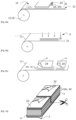
- an installation materializing a first step of a method for forming a discrete segmented fold 8 according to the invention During this first step, a continuous single-layer sheet 1 of fibers wound in the form of a reel 11 is directed to a cutting station 12 within which it undergoes a cutting operation aimed at producing segments 4.
- the continuous release liner 2 may advantageously consist of a paper support covered with a silicone-based layer.
- the continuous release liner 2 will in particular have the capacity to be easily separated from the layer of fibers 3, without causing migration of the fibers onto the continuous release liner 2.
- the fibers of fiber layer 3 may consist of carbon fibers, glass fibers, aramid fibers, or even ceramic or natural fibers.
- the fibers of the continuous prepreg layer 3 may be embedded in a thermosetting resin, such as an epoxy, polyester, vinylester, bismaelimide, polymide, phenolic resin, or in a thermoplastic resin, such as a polyetherimide (PEI), polyphenylensulfide (PPS), polyetheretherketone (PEEK) and polyamide (PA) resin.
- a thermosetting resin such as an epoxy, polyester, vinylester, bismaelimide, polymide, phenolic resin
- a thermoplastic resin such as a polyetherimide (PEI), polyphenylensulfide (PPS), polyetheretherketone (PEEK) and polyamide (PA) resin.
- PEI polyetherimide
- PPS polyphenylensulfide
- PEEK polyetheretherketone
- PA polyamide
- An advantage of the present invention is that any continuous single-layer sheet 1 as described that is commercially available or from scraps from a process for manufacturing another large composite part can be used in the process of the present invention.
- This is a considerable advantage, since continuous single-layer sheets 1 already qualified in other processes can be used in applications in the fields of aeronautics, medicine or automobiles, thereby facilitating the procedures for qualifying a new product, which can be very long and costly in these fields.
- the reuse of scraps of material from other processes for manufacturing large high-performance composite parts, in particular in the field of aeronautics, in a process for manufacturing high-performance composite parts with complex geometries represents a considerable saving in the production of composite parts used in the manufacture of an aircraft.
- the cutting station 12 may be a cutting head, as illustrated in the figure 1 , or a cutting roller having a series of raised cutting lines defining a cutting pattern.
- the cutting station 12 is particularly configured to cut only the continuous prepreg layer 3, thereby forming a continuous segmented prepreg layer 3s while leaving the continuous release liner 2 intact. In this way, the segments 4 formed in the continuous segmented prepreg layer 3s are held together at the by means of the continuous release liner 2.
- This partial cutting of the continuous single-layer sheet 1 thus prevents segments 4 from no longer being connected to the rest of the continuous single-layer sheet 1 due to the absence of connection zones. Handling of the segmented continuous sheet 5 obtained following the partial cutting operation is therefore facilitated.
- the segments 4 are advantageously oriented in a single direction.
- “in a single direction” means “in a single direction to within 5°”.
- Such unidirectional segments provide good mechanical characteristics, such as high tensile and bending strengths for example.
- the segments 4 comprise two opposite sides parallel to the longitudinal direction D, thus limiting the number of unnecessary cuts of the reinforcing fibers, thus maximizing their length in the segmented continuous sheet 5.
- the segments 4 may have an identical shape, in particular a rectangular shape.
- they will have a length preferably parallel to the longitudinal direction D, which is between 10 mm and 100 mm, preferably substantially equal to 50 mm, and a width between 5 mm and 50 mm, preferably substantially equal to 8 mm.
- the segments 4 are advantageously positioned in a staggered manner. This staggered positioning of the segments 4 in fact provides improved mechanical characteristics in the part to be formed.
- the segmented continuous sheet 5 thus produced can then be packaged in the form of a reel 13 before being transferred to a reworking machine at which a transverse cutting operation of the segmented continuous sheet 5 is carried out so as to form one or more series of discrete segmented folds 8 as illustrated in the Figures 2 to 4 .
- the segmented continuous web 5 is cut along two cutting lines 6, 7 parallel to a cutting direction (d1, d2, d3), oriented obliquely relative to the longitudinal direction (D).
- the segmented continuous web 5 is cut over its entire width and thickness, including the release liner, thus forming a discrete segmented preimpregnated ply 8 formed by a discrete segmented preimpregnated layer 3ds and a discrete release liner 2d.
- the cutting lines 6, 7 form a cutting angle ( ⁇ ) with the longitudinal direction (D); Since the fibers of a segmented continuous web 5 are parallel to the longitudinal direction (D), they form with the cut sides of the discrete segmented ply 8 thus obtained the cutting angle ( ⁇ ).
- a structure such as a ply or a laminate, is considered to be discrete if it has a geometry inscribed in a rectangle of length (L) and width (w) with a length-to-width ratio (L/w) less than or equal to 20 (i.e., L/w ⁇ 20).
- a structure, such as a sheet or ribbon, is considered to be continuous if it has a geometry inscribed in a rectangle of length (L) and width (w) with a length-to-width ratio (L/w) greater than 20 (i.e., L/w > 20).
- the segmented continuous sheet 5 is unwound from a reel 13 to a cutting station 14 in which it is in particular cut over its entire width and thickness, including the continuous non-stick liner 2, along two cutting lines 6, 7 parallel and oriented obliquely relative to the longitudinal direction D.
- the cutting lines 6, 7 thus form a discrete segmented fold 8 in the shape of a parallelogram and, preferably, in the shape of a diamond.
- This discrete segmented fold 8 is in particular defined by a main direction d1 which, at Figures 2 and 2a , is parallel to the cutting lines 6, 7.
- This cutting direction d1 makes an angle of 45° with the longitudinal direction D of the segmented continuous sheet 5.
- the fibers are oriented at an angle ⁇ equal to +45° relative to the sides of the ply which have been cut according to the cutting direction d1.
- the cutting station 14 for cutting the segmented continuous web 5 into a series of discrete segmented folds 8 may comprise a table on the plane (X, Y) of which a cutting head moves, which may be a rotating blade, a laser, a water jet or any other cutting head available on the market for cutting the segmented continuous web 5 into discrete segmented folds 8 precisely and cleanly.
- the segmented continuous sheet 5 is cut over its entire width and thickness, including the continuous release liner 2, along two cutting lines 6, 7 that are parallel and oriented obliquely relative to the longitudinal direction D.
- the cutting lines 6', 7 thus form a discrete segmented fold in the shape of a parallelogram.
- This discrete segmented fold 8 is notably defined by a cutting direction d2, which is parallel to the cutting lines 6, 7.
- This main direction d2 makes an angle of +45° with the longitudinal direction D of the segmented continuous sheet 5.
- the fibers are oriented at an angle ⁇ equal to +135° with the cutting direction d2.
- the segmented continuous sheet 5 is cut over its entire width and thickness, including the continuous release liner 2, along two cutting lines 6', 7' that are parallel and oriented in a cutting direction d3 perpendicular to the longitudinal direction D.
- the cutting lines 6", 7" thus form a discrete segmented ply 8 in the shape of a rectangle.
- This discrete segmented ply 8 is notably defined by a cutting direction d3, which is parallel to the cutting lines 6, 7.
- This cutting direction d3 makes an angle of 90° with the longitudinal direction D of the segmented continuous sheet 5.
- the fibers are oriented at an angle ⁇ equal to 90° with the main direction d3.
- the cutting lines 6, 7 are not necessarily parallel to each other, thus also being able to form discrete segmented plies 8 in the shape of triangles or trapezoids.
- the transverse cutting lines may be oriented relative to the longitudinal direction D such that, in each of the preimpregnated unit plies, the fibers will be oriented at +60°, or at -60°, at +30°, or at -30°, or even at 90° relative to a main direction defined by the cut sides of the discrete segmented ply 8.
- the discrete segmented folds 8 formed by transverse cutting of the continuous segmented sheet 5 may be called “treated folds”, the two expressions being considered synonymous.
- the discrete segmented prepreg layer 3ds - and not the discrete release liner 2d - comprises segments 4 cut over its entire thickness and arranged in a staggered pattern.
- the segments thus cut give the discrete segmented ply 8 a flexibility and drapability superior to most unidirectional prepreg plies of long fibers available on the market.
- the segments have a geometry comprising two opposite sides parallel to the longitudinal direction (D) having identical dimensions within the discrete segmented ply.
- the geometry of the segments is inscribed in a rectangle with a length measured along the longitudinal direction (D) and a width measured in a direction perpendicular to the longitudinal direction.
- the length measured along the longitudinal direction (D) of the rectangle in which each segment 4 is inscribed may be between 10 mm and 200 mm, preferably between 50 and 150 mm, more preferably between 70 and 130 mm or substantially equal to 100 mm.
- the width of the rectangle in which each segment is inscribed may be less than or equal to the length and may be between 5 mm and 100 mm, preferably between 8 and 50 mm or substantially equal to 10 mm. The smaller the width, the more flexible the treated ply is in the direction normal to the longitudinal direction (D).
- the segments (4) may have a rectangular or trapezoidal shape.
- the segments have a rectangular shape, with the 'short sides' defining the width of the rectangle being curved, preferably semi-circular, forming a concave short side at one end of the segment and a convex short side at the other end, the convex short side matching the geometry of the concave short side.
- This geometry gives the segmented discrete fold greater flexibility in the plane of the fold, allowing the segments to be bent like a chain, the links formed by the segments being connected to each other by hinges formed by the concave short sides matching the convex short sides.
- the discrete release liner (2d) sufficiently adheres to the discrete segmented prepreg layer (3ds) to ensure that the segments of the discrete segmented prepreg layer 3ds do not shift or fall off during handling of the treated ply.
- the discrete release liner (2d) must, however, be easily removed when stacking treated plies 8 to form a discrete segmented multilayer mat 80 composed of a stack of discrete prepreg layers 3d including at least one discrete segmented prepreg layer 3ds.
- the discrete segmented multilayer mat 80 of the present invention is distinguished from prior art discrete multilayer mats in that at least one of the (N+1) discrete 3d prepreg layers, preferably all of the (N+1) discrete 3d prepreg layers are discrete segmented 3ds prepreg layers as defined above with reference to the discrete segmented prepreg plies 8. They are also distinguished in that at least one discrete segmented 3ds prepreg layer has a triangle, trapezoid or parallelogram geometry, preferably a rhombus. A rectangle is a parallelogram with four right angles and a square is a rhombus with four right angles.
- the geometry of the discrete segmented 3ds prepreg layer may be a trapezoid or parallelogram having at least two angles different from 90°.
- Such fold geometries are obtained when manufacturing discrete segmented folds 8 by cutting the continuous segmented web 5 along two cutting lines 6, 7 parallel to cutting directions (d1, d2, d3), each of the cutting directions forming a cutting angle ( ⁇ ) with the longitudinal direction (D).
- This is advantageous, since the side of the discrete segmented ply cut along the cutting direction (d1) forming an angle ( ⁇ ) defines a reference allowing when stacking a discrete segmented ply 8 on a discrete prepreg layer 3d, to define exactly a desired reinforcement angle ( ⁇ ) with respect to the direction of the fibers in the adjacent layers, by aligning the corresponding sides of the discrete segmented ply 8 and the discrete prepreg layer 3d.
- the reinforcement angle ( ⁇ ) is not necessarily equal to the cutting angle ( ⁇ ) because, as illustrated in Figure 6a , the segmented discrete ply 8 can be rotated before placing it on the discrete 3d prepreg layer with one side aligned with the corresponding side of the latter.
- An automatic fiber placement machine is optimized to manufacture large parts and is poorly suited to place fibers or tapes on small strips, as is often necessary for use with parts with complex geometry. Since it is difficult to automate on an industrial scale the formation of sub-preforms and final preforms for parts with complex geometry and generally too small for an AFP machine to be effective, the present invention has moved the automation step further upstream of the formation of the sub-preform or final preform. This is how the step of cutting segments 4 on a continuous single-layer sheet (1) fed continuously along the longitudinal direction (D) whatever the desired reinforcement angle ( ⁇ ).
- the discrete segmented ply 8 can easily be stacked with a reinforcement angle ( ⁇ ) of 0° or 90°, simply by aligning a cut side or an uncut side with the longitudinal direction (D), for example by aligning it with the discrete prepreg layer on which the discrete segmented ply 8 is placed, by rotating it or not by 90°.
- a discrete segmented multi-layer mattress 80 may be produced from a continuous ribbon of discrete stacks as illustrated in FIG. Figure 10 , by depositing a series of stacks of N discrete prepreg layers on a continuous ribbon 15, as illustrated in Figures 5 to 10 . At least one of the N discrete 3d prepreg layers, preferably all of the N discrete 3d prepreg layers are discrete segmented 3ds prepreg layers.
- the method of this variant comprises the following steps.
- a continuous tape (15) is provided, consisting of a continuous single-ply web 1 or a segmented continuous web 5, or a continuous release liner (2) as defined in relation to the method of manufacturing a segmented discrete ply 8, supra.
- a series of stacks each composed of N discrete 3d prepreg layers stacked on top of each other are deposited on one side of the continuous tape 15 not comprising the continuous release liner 2 or on the continuous release liner (2) if the continuous tape (15) is formed by a continuous release liner (2), where N ⁇ N and N ⁇ 1, to form the continuous ribbon of discrete stacks.
- Each stack is deposited on the continuous ribbon by the following steps
- At least one discrete prepreg ply, preferably all discrete prepreg plies are segmented discrete plies 8 obtained by the method described above, in which the discrete prepreg layer 3d is formed by the discrete segmented prepreg layer 3ds.
- a series of discrete segmented multi-layer mattresses 80 each comprising (N + 1) discrete 3d prepreg layers can be obtained simply by cutting the continuous ribbon 15 of the continuous ribbon of discrete stacks between two adjacent discrete stacks, as illustrated in Figure 10 .
- a continuous ribbon 15 is unwound from a reel 13 to a station (not shown) for depositing discrete pre-impregnated plies.
- the continuous ribbon 15 is a segmented continuous sheet 5 comprising segments 4 formed by cutting the continuous pre-impregnated layer 3 (but not the continuous release liner 2).
- the idea of this method of the present invention is to deposit on one face of the continuous tape 15 not comprising the continuous release liner 2 a series of stacks of N discrete prepreg plies laid side by side on the continuous tape 15 to form a continuous tape 15 of discrete stacks which can be wound to form a reel which is easy to store and transport.
- the continuous tape 15 can be cut between two adjacent discrete stacks to obtain discrete segmented multilayer mattresses 80.
- Each discrete stack is formed of N discrete prepreg layers stacked on top of each other, at least one of which, preferably all of the N discrete 3d prepreg layers of each stack is a discrete segmented 3ds prepreg layer.
- the number N of discrete prepreg layers may vary from stack to stack, but in general, it is preferred that all discrete stacks of a single continuous ribbon 15 of discrete stacks are formed of the same number N of discrete 3d,3ds prepreg layers.
- a series of treated folds 8, conforming to those represented on the figure 2 are deposited on the continuous tape 15.
- each of the treated plies 8 is oriented such that its fiber layer comes into contact with the fiber layer of the continuous tape 15. It is preferred to deposit the face of the discrete prepreg ply not having a discrete release liner 2d of the discrete prepreg ply in contact with the face of the continuous tape 15 and to remove the discrete release liner 2d only after the ply has been deposited. If this is not possible, the discrete release liner 2d must be removed before depositing the discrete prepreg ply on the continuous tape 15, taking care that the segments 4 remain in place if it is a treated ply 8.
- This removal can be carried out according to the operating procedure shown in the Figures 9a to 9c .
- a first discrete prepreg ply to be deposited is oriented such that its discrete release liner 2d is positioned above, its discrete prepreg layer 2d, 2ds resting on the continuous prepreg layer of the continuous tape 15.
- a second operation shown in the figure 9b the complex formed by the continuous ribbon 15 covered with the first discrete pre-impregnated ply is compacted under the effect of a mechanical pressure (P) exerted on the upper surface of the discrete pre-impregnated ply.
- P mechanical pressure
- This compaction may also be carried out by means of a vacuum created above the first discrete pre-impregnated ply.
- the discrete 2d release liner of the first discrete prepreg ply is removed, leaving the discrete prepreg layer of the first discrete prepreg ply exposed on the top of the forming stack.
- a series of discrete prepreg plies comprising at least one treated ply, preferably all discrete prepreg plies including the first discrete prepreg ply are treated plies 8 (i.e., segmented discrete plies 8), for example, as shown in the figure 4 , are deposited either directly on the continuous tape 15, or on the first discrete pre-impregnated ply previously deposited on the continuous tape 15.
- treated plies 8 i.e., segmented discrete plies 8
- each of the discrete pre-impregnated plies is oriented in such a way that that its discrete prepreg layer 3d, 3ds contacts the discrete prepreg layer 3d, 3ds of the continuous tape 15 or with the discrete prepreg layer 3d, 3ds of the first discrete prepreg layer.
- the sequence of reinforcement angles ( ⁇ ) of the fibers of each ply can be varied.
- a reinforcement angle ( ⁇ ) can be easily obtained with the fibers of an adjacent discrete (segmented) prepreg layer 3d, 3ds by aligning one side of the discrete segmented ply 8 cut along the cutting direction (d1, d2, d3) with one side of the adjacent discrete (segmented) prepreg layer (3d, 3ds).
- the cutting angle, ⁇ 90° between the longitudinal direction (D) and each of the two cutting lines 6, 7 of the discrete segmented prepreg ply 8, forming a rectangle (or square).
- a unidirectional stack can be formed, with the fibers of all discrete prepreg plies oriented at 0°, suitable for the production of a part with complex geometry that will be stressed mainly in the longitudinal direction (D).
- a quasi-isotropic stack can also be formed with reinforcement angle sequences of (+45° / 0° / -45° / 90°) and its mirror per discrete stack unit, each consisting of 4 discrete prepreg layers. Any other reinforcement angle sequence ( ⁇ ) is possible depending on the geometry and specifications of the part to be produced.
- a series of treated folds 8, conforming to those represented on the figure 3 are deposited either directly on the continuous tape 15, or on the discrete pre-impregnated (segmented) layers previously deposited on the continuous tape 15.
- each of the treated plies 8 is oriented such that its discrete pre-impregnated (segmented) layer 3d, 3ds comes into contact with the discrete pre-impregnated (segmented) layer 3d, 3ds of the continuous tape 15 or with the layer discrete 3d prepreg (segmented), 3ds of the last treated ply 8 or not of a stack in formation.
- each discrete segmented multilayer mattress thus obtained is therefore formed of (N + 1) discrete preimpregnated layers, of which N discrete preimpregnated layers are formed by the N discrete preimpregnated plies of each discrete stack + one discrete preimpregnated layer is formed by the continuous ribbon 15 which has been cut (cf. Figure 10 ).
- the method of manufacturing a discrete segmented multilayer mattress 90 of the present invention is distinguished from prior art methods in that at least one discrete prepreg ply, preferably all discrete prepreg plies are segmented discrete plies 8 as described above of which the discrete prepreg layer 3d is formed by the discrete segmented prepreg layer 3ds.
- each discrete segmented prepreg layer 3ds can be controlled during its stacking, by aligning the corresponding sides of the discrete segmented ply 8 and the discrete segmented prepreg layer 3ds on which the discrete segmented ply 8 is placed.
- the discrete segmented multi-layer mat 80 of the present invention makes it possible to produce high-performance composite parts having complex geometries.
- the segments 4 cut from the discrete segmented prepreg layers 3ds the discrete segmented multi-layer mat 80 can adapt to and conform to complex mold shapes, while maintaining good alignment of the reinforcing fibers along their respective reinforcement angles ( ⁇ ).
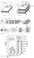
- FIG. 12 illustrates a process for manufacturing a high-performance composite part with complex geometry.
- the steps in the top line of the Figure 12 illustrate the manufacture of a discrete segmented multilayer mattress 80 according to the present invention and already widely discussed above. From a discrete segmented multilayer mattress 80 having the desired sequence of reinforcement angles ( ⁇ ), it can be cut to form a sub-preform 80p whose geometry is adapted to a geometry of the composite part 90. If necessary, different sub-preforms 80p can be assembled to form a final preform 90p of the composite part. This step is optional and can be used, for example, if particular extra thicknesses or reinforcement angles ( ⁇ ) are locally necessary.
- the sub-preform 80p or the final preform 90p is then deposited in a mold 100 heated to the processing temperature (T). Pressure is applied while maintaining the processing temperature in order to consolidate the sub-preform 80p or the final preform 90p and thus form the composite part 90.
- the mold can be maintained at the processing temperature, ready to receive a new sub-preform 80p or final preform 90p, after cleaning the mold, if necessary. If the matrix is a thermoplastic polymer, the mold temperature must be lowered below the solidification temperature of the matrix, for example below the crystallization temperature for semi-crystalline polymers, such as PEEK, PEKK, PA, PEI, PBS, etc.
- a quasi-isotropic composite part can be produced with a discrete segmented multilayer mat 80 or a final preform 90p whose reinforcement angles ( ⁇ ) vary between the discrete 3d prepreg layers between 0°, ⁇ 45°, and 90°.
- a quasi-orthotropic composite part can be produced with a discrete segmented multilayer mat 80 or a final preform 90p whose all fibers are oriented at a same reinforcement angle ( ⁇ ) of 0°, thus forming a unidirectional (UD) composite.
- any mixed configuration can be obtained with a discrete segmented multilayer mat 80 or a final preform 90p whose reinforcement angles ( ⁇ ) vary between the discrete 3d prepreg layers according to the locally desired mechanical properties.
- Discrete segmented multi-layer mats 80 were produced from continuous single-ply webs 1 of aerospace grade unidirectional carbon fiber reinforced epoxy available from Hexcel.
- Discrete segmented plies 8 of prepregs according to the present invention were produced by cutting segments 4 from the continuous prepreg layer 1. The segments are rectangular with dimensions 50 ⁇ 8 mm arranged in a staggered pattern.
- Quasi-isotropic 80 discrete segmented multilayer mattresses were produced with four resulting discrete 8 segmented prepreg plies, with a reinforcement angle sequence ( ⁇ ) of 0° / +45° / 90° / -45°.
- Quasi-isotropic composite plates were produced by compression molding. The samples are referred to in the Figure 13 as “INV-Quasi-iso”.
- Unidirectional discrete segmented 80 multilayer mattresses were produced with four discrete segmented 8 prepreg plies obtained in this way, with all fibers oriented in the same direction with a reinforcement angle ( ⁇ ) of 0°.
- Composite plates were produced by compression molding with SMC sheets available from HEXCEL as HexMC Aero, 8552. Samples are referenced in the Figure 13 as “CEx-SMC”.
- the samples are referred to in the Figure 13 as “CEx-UD”.
- FIG. 14 schematically positions on a graph showing the mechanical performance of a composite part as a function of the complexity of the geometry of the processable parts from the different preforms represented.
- UD unidirectional
- Such sequences allow to improve the mechanical properties in directions other than 0°, but reduce the properties in the longitudinal direction depending on the proportion of fibres which is not oriented with a reinforcement angle of 0°.
- the change of fibre orientation sequences of the prepreg preforms has no significant influence on the flexibility of the preform.
- Such preforms therefore have a very low potential to form parts with complex geometries.
Landscapes
- Engineering & Computer Science (AREA)
- Mechanical Engineering (AREA)
- Chemical & Material Sciences (AREA)
- Composite Materials (AREA)
- Textile Engineering (AREA)
- Reinforced Plastic Materials (AREA)
- Moulding By Coating Moulds (AREA)
- Processing And Handling Of Plastics And Other Materials For Molding In General (AREA)
Claims (16)
- Verfahren zur Herstellung einer segmentierten diskreten Lage (8) zur Bildung einer diskreten segmentierten Mehrschichtmatte, wobei das Verfahren die folgenden Schritte umfasst:a) Bereitstellen einer durchgehenden einschichtigen Bahn (1), die Folgendes umfasst,• eine durchgehende vorimprägnierte Schicht (3), die aus unidirektionalen Fasern gebildet ist, die parallel zu einer Längsrichtung (D) angeordnet sind, wobei die Fasern in eine Harzmatrix eingebettet sind,• einen durchgehenden Antihaftliner (2), der auf eine Seite der durchgehenden vorimprägnierten Schicht aufgebracht ist,b) Zuschneiden der durchgehenden einschichtigen Bahn (1), die in Schritt a) bereitgestellt wird, um in der durchgehenden vorimprägnierten Schicht (3) Segmente (4) zu bilden, die versetzt angeordnet sind, und so eine segmentierte durchgehende Bahn (5) zu bilden, wobei der Zuschnitt so durchgeführt wird, dass der durchgehende Antihaftliner (2) intakt gelassen wird;c) Zuschneiden in Querrichtung der segmentierten durchgehenden Bahn (5), die in Schritt b) erhalten wird, gemäß zweier Zuschnittlinien (6, 7), die parallel zu Zuschnittrichtungen (d1, d2, d3) verlaufen, die schräg zu Längsrichtung (D) orientiert sind, wobei die segmentierte durchgehende Bahn (5) über ihre gesamte Breite und Dicke zugeschnitten wird, einschließlich des Antihaftliners, wobei auf diese Weise eine segmentierte diskrete Lage (8) gebildet wird, die von einer diskreten segmentierten vorimprägnierten Schicht (3ds) und dem Antihaftliner gebildet ist, und wobei die Zuschnittlinien (6, 7) einen Zuschnittwinkel (α) mit der Längsrichtung (D) bilden;wobei eine durchgehende Bahn eine Bahn mit einer Geometrie ist, die in einem Rechteck mit einer Länge (L) und einer Breite (1) mit einem Verhältnis der Länge zur Breite (L/l) über 20 (d.h. L /l > 20) eingeschrieben ist, und eine diskrete Lage eine Lage mit einer Geometrie ist, die in einem Rechteck mit einer Länge (L) und einer Breite (1) mit einem Verhältnis der Länge zur Breite (L/l) kleiner als oder gleich 20 (d.h. L /1 ≤ 20) eingeschrieben ist.
- Verfahren nach einem der vorhergehenden Ansprüche, wobei der Zuschnittwinkel (α) aus den folgenden Werten gewählt wird, 90°, +45°, -45°, +60°, -60°, +30°, -30°, auf ± 5° genau.
- Verfahren nach Anspruch 1 oder 2, wobei der durchgehende Antihaftliner (2) von einem Träger aus Papier gebildet ist, der mit einer Schicht aus Silikon bedeckt ist.
- Verfahren nach einem der Ansprüche 1 bis 3, wobei die Fasern der durchgehenden vorimprägnierten Schicht von Karbon-, Glas-, Aramid-, Keramik- oder Naturfasern gebildet sind und entweder• in einem wärmehärtenden Harz, das vorzugsweise ein Epoxidharz umfasst, oder• in einem thermoplastischen Polymer eingebettet sind.
- Verfahren nach einem der vorhergehenden Ansprüche, wobei in ein und derselben segmentierten diskreten Lage (8) die Segmente (4) eine Geometrie aufweisen, die zwei gegenüberliegende Seiten umfasst, die parallel zur Längsrichtung (D) verlaufen, mit gleichen Abmessungen innerhalb der segmentierten diskreten Lage, wobei die Geometrie der Segmente in einem Rechteck mit einer Länge, die entlang der Längsrichtung (D) gemessen wird, die vorzugsweise zwischen 10 mm und 200 mm, vorzugsweise zwischen 50 und 150 mm, weiter bevorzugt zwischen 70 und 130 mm liegt oder im Wesentlichen gleich 100 mm ist, und einer Breite, die vorzugsweise zwischen 5 mm und 50 mm liegt, vorzugsweise im Wesentlichen gleich 8 mm ist, eingeschrieben ist.
- Verfahren nach einem der vorhergehenden Ansprüche, wobei die durchgehende einschichtige Bahn (1) aus Abfällen stammt, die in einem vorherigen Verfahren zur Herstellung von Verbundteilen nicht verwendet wurden.
- Verfahren zur Herstellung eines durchgehenden Bands aus diskreten Stapeln, umfassend die folgenden Schritte:a) Bereitstellen eines durchgehenden Bands (15), das aus einer durchgehenden einschichtigen Bahn (1) nach Anspruch 1a) oder einer segmentierten durchgehenden Bahn (5) nach Anspruch 1b) oder einem durchgehenden Antihaftliner (2) gebildet ist,b) Auflegen, auf eine Seite des durchgehenden Bands (15), die nicht den durchgehenden Antihaftliner (2) umfasst, oder auf den durchgehenden Antihaftliner (2), wenn das durchgehende Band (15) von einem durchgehenden Antihaftliner (2) gebildet ist, einer Reihe von Stapeln, die jeweils aus N diskreten vorimprägnierten Schichten (3d) zusammengesetzt sind, die aufeinander gestapelt sind, wobeidadurch gekennzeichnet, dass wenigstens eine diskrete vorimprägnierte Lage, vorzugsweise alle diskreten vorimprägnierten Lagen, segmentierte diskrete Lagen (8) sind, die durch das Verfahren nach einem der Ansprüche 1 bis 6 erhalten werden, wobei die diskrete vorimprägnierte Schicht (3d) von der diskreten segmentierten vorimprägnierten Schicht (3ds) nach Anspruch 1c) gebildet ist,
 • Bereitstellen von N diskreten vorimprägnierten Lagen, umfassend einerseits,∘ die diskrete vorimprägnierte Schicht (3d), die unidirektionale Fasern umfasst, die in eine Harzmatrix eingebettet sind, und∘ einen diskreten Antihaftliner (2d), der auf eine Seite der diskreten vorimprägnierten Schicht (3d) aufgebracht ist,• sequentielles Auflegen der N diskreten vorimprägnierten Lagen auf das durchgehende Band (15) durch Entfernen des diskreten Antihaftliners (2d) von jeder diskreten vorimprägnierten Lage, bevor eine neue diskrete vorimprägnierte Lage darauf gelegt wird, und, wahlweise, Kompaktieren der so gestapelten diskreten vorimprägnierten Lagen, so dass,∘ die diskrete vorimprägnierte Schicht (3d) einer ersten diskreten vorimprägnierten Lage (3d) mit der durchgehenden vorimprägnierten Schicht (3) des durchgehenden Bands (15) in Kontakt steht, auf das die erste diskrete vorimprägnierte Schicht gelegt ist,∘ die diskrete vorimprägnierte Schicht (3d) der zweiten bis zur N-ten diskreten vorimprägnierten Lage mit der diskreten vorimprägnierten Schicht (3d) der angrenzenden diskreten vorimprägnierten Lagen in Kontakt stehen, mit denen sie in Kontakt stehen,∘ die N-te diskrete vorimprägnierte Schicht (3d) eine freie Seite aufweist, auf der der diskrete Antihaftliner (2d) aufgelegt ist, wodurch die N-te diskrete vorimprägnierte Lage gebildet wird,
 - Verfahren nach Anspruch 7, umfassend den Schritt des Zuschneidens des durchgehenden Bands (15) des durchgehenden Bands aus diskreten Stapeln zwischen zwei aneinandergrenzenden diskreten Stapeln, um eine Reihe von diskreten segmentierten Mehrschichtmatten (80) zu erhalten, die jeweils (N + 1) diskrete vorimprägnierte Schichten (3d) umfassen.
- Verfahren zur Herstellung einer diskreten segmentierten Mehrschichtmatte (80), die (N + 1) diskrete vorimprägnierte Schichten (3d) umfasst, umfassend die folgenden Schritte,• Bereitstellen von (N+1) diskreten vorimprägnierten Lagen, jeweils umfassend, einerseits,∘ eine diskrete vorimprägnierte Schicht (3d), die unidirektionale Fasern umfasst, die in eine Harzmatrix eingebettet sind, und∘ einen diskreten Antihaftliner (2d), der auf eine Seite der diskreten vorimprägnierten Schicht (3d) aufgebracht ist,• Legen einer ersten diskreten vorimprägnierten Lage (3d) auf den Antihaftliner, wodurch die diskrete vorimprägnierte Schicht (3d) freigelegt wird,• sequentielles Auflegen, auf die erste diskrete vorimprägnierte Lage (3d), von N diskreten vorimprägnierten Lagen durch Entfernen des diskreten Antihaftliners (2d) von jeder diskreten vorimprägnierten Lage, bevor eine neue diskrete vorimprägnierte Lage darauf gelegt wird, und wahlweise, Kompaktieren der so gestapelten diskreten vorimprägnierten Lagen, so dass,dadurch gekennzeichnet, dass wenigstens eine diskrete vorimprägnierte Lage, vorzugsweise alle diskreten vorimprägnierten Lagen, segmentierte diskrete Lagen (8) nach einem der Ansprüche 1 bis 6 sind, wobei die diskrete vorimprägnierte Schicht (3d) von der diskreten segmentierten vorimprägnierten Schicht (3ds) nach Anspruch 1c) gebildet ist,∘ die diskrete vorimprägnierte Schicht (3d) jeder diskreten vorimprägnierten Lage (3d) mit der diskreten vorimprägnierten Schicht (3d) der angrenzenden diskreten vorimprägnierten Lagen in Kontakt steht, mit denen sie in Kontakt stehen,∘ eine (N+1)-te diskrete vorimprägnierte Schicht (3d) eine freie Seite aufweist, auf der der diskrete Antihaftliner (2d) aufgelegt ist, wodurch die (N+1)-te diskrete vorimprägnierte Lage gebildet wird,
- Verfahren nach einem der Ansprüche 7 bis 9, wobei die Fasern einer bestimmten diskreten vorimprägnierten Schicht (3d) einen Verstärkungswinkel (β) zwischen 0 und 180° (d.h. β = 0 bis 180°) mit den Fasern der diskreten vorimprägnierten Schichten (3d) desselben diskreten Stapels bilden, die an die bestimmte diskrete vorimprägnierte Schicht (3d) angrenzen und mit ihr in Kontakt stehen, wobei vorzugsweise alle diskreten vorimprägnierten Schichten (3d) eines diskreten Stapels diskrete segmentierte vorimprägnierte Schichten (3ds) sind, deren Zuschnittwinkel 90° oder +45° betragen und deren Verstärkungswinkel (β) gleich dem Zuschnittwinkel (α) sind, dem ein Vielfaches (n) von 45° hinzuaddiert ist, mit n = 0 bis 4 (d.h. β = α + n 45°, mit n = 0 bis 4) .
- Segmentierte durchgehende Bahn (5), die durch den Schritt b) des Verfahrens nach Anspruch 1 erhalten wurde und Folgendes umfasst,• eine durchgehende segmentierte vorimprägnierte Schicht (3s), die eine Dicke aufweist und aus unidirektionalen Fasern gebildet ist, die parallel zur Längsrichtung (D) angeordnet sind, wobei die Fasern in eine Harzmatrix eingebettet sind, und• einen durchgehenden Antihaftliner (2), der auf eine Seite der durchgehenden segmentierten vorimprägnierten Schicht (3s) aufgebracht ist,dadurch gekennzeichnet, dass nur die durchgehende segmentierte Schicht (3s) Segmente (4) umfasst, die über ihre gesamte Dicke zugeschnitten sind und versetzt angeordnet sind.
- Imprägnierte segmentierte diskrete Lage (8), die durch ein Verfahren nach einem der Ansprüche 1 bis 6 erhalten wurde, mit einer diskreten Geometrie, die in einem Rechteck mit einer Länge (L) und einer Breite (1) mit einem Verhältnis der Länge zur Breite (L/l) kleiner als oder gleich 20 (d.h. L /l ≤ 20) eingeschrieben ist und Folgendes umfasst,• eine diskrete segmentierte vorimprägnierte Schicht (3ds), die eine Dicke aufweist und aus unidirektionalen Fasern gebildet ist, die parallel zur Längsrichtung (D) angeordnet sind, wobei die Fasern in eine Harzmatrix eingebettet sind, und• einen diskreten Antihaftliner (2d), der auf eine Seite der diskreten segmentierten vorimprägnierten Schicht (3ds) aufgebracht ist,dadurch gekennzeichnet, dass nur die diskrete segmentierte Schicht (3ds) Segmente (4) umfasst, die über ihre gesamte Dicke zugeschnitten sind und versetzt angeordnet sind.
- Diskrete segmentierte Mehrschichtmatte (80), die durch ein Verfahren nach einem der Ansprüche 8 bis 10 erhalten wurde und aus einem Stapel diskreter vorimprägnierter Schichten (3d) zusammengesetzt ist, umfassend, einerseits,• (N+1) diskrete vorimprägnierte Schichten (3d) aus unidirektionalen Fasern, die in eine Harzmatrix eingebettet sind, wobei die (N+1) diskreten vorimprägnierten Schichten aufeinander gestapelt sind und• einen diskreten Antihaftliner (2d), der auf eine freie Seite von jeder einer ersten und einer (N+1)-ten diskreten vorimprägnierten Schicht aufgebracht ist, der die (N+1) diskreten vorimprägnierten Schichten sandwichartig einschließt,dadurch gekennzeichnet, dass wenigstens eine der (N+1) diskreten vorimprägnierten Schichten (3d), vorzugsweise alle (N+1) diskreten vorimprägnierten Schichten (3d), diskrete segmentierte vorimprägnierte Schichten (3ds) nach Anspruch 11 sind, und dadurch, dass wenigstens eine diskrete segmentierte vorimprägnierte Schicht (3ds) eine Dreiecks-, Trapez- oder Parallelogrammgeometrie aufweist, vorzugsweise mit wenigstens zwei Winkeln, die sich von 90° unterscheiden.
- Diskrete segmentierte Mehrschichtmatte (80) nach Anspruch 12, wobei die Fasern einer bestimmten diskreten vorimprägnierten Schicht (3d) einen Verstärkungswinkel (β) zwischen 0 und 180° (d.h. β = 0 bis 180°) mit den Fasern der diskreten vorimprägnierten Schichten (3d) desselben diskreten Stapels bilden, die an die bestimmte diskrete vorimprägnierte Schicht (3d) angrenzen und mit ihr in Kontakt stehen, wobei vorzugsweise alle diskreten vorimprägnierten Schichten (3d) eines diskreten Stapels diskrete segmentierte vorimprägnierte Schichten (3ds) sind, deren Zuschnittwinkel 90° oder +45° betragen und deren Verstärkungswinkel (β) gleich dem Zuschnittwinkel (α) sind, dem ein Vielfaches (n) von 45° hinzuaddiert ist, mit n = 0 bis 4 (d.h. β = α + n × 45°, mit n = 0 bis 4).
- Verfahren zur Herstellung eines Verbundteils (90) umfassend,• Bereitstellen einer diskreten segmentierten Mehrschichtmatte (80), die durch ein Verfahren nach Anspruch 9 oder 10 erhalten wurde,• Zuschneiden der diskreten segmentierten Mehrschichtmatte (80), um einen Teilvorformling (80p) zu bilden, dessen Geometrie an eine Geometrie des Verbundteils (90) angepasst ist,• wahlweise, Zusammensetzen verschiedener Teilvorformlinge (80p), um einen finalen Vorformling (90p) des Verbundteils (90) zu bilden,• Einlegen des Teilvorformlings (80p) oder des finalen Vorformlings (90p) in eine Form (100),• Anwenden von Druck und Hitze, um den Teilvorformling (80p) oder den finalen Vorformling (90p) zu verfestigen und so das Verbundteil (90) zu bilden, und• Entnehmen des Verbundteils (90) aus der Form.
- Verfahren nach Anspruch 15, wobei wenigstens ein Abschnitt des Verbundteils (90) entweder• quasi-isotrop mit einer diskreten segmentierten Mehrschichtmatte (80) oder einem finalen Vorformling (90p) hergestellt wird, deren Verstärkungswinkel (β) zwischen den diskreten vorimprägnierten Schichten (3d) zwischen 0°, ±45° und 90° variieren, oder• quasi-orthotrop mit einer diskreten segmentierten Mehrschichtmatte (80) oder einem finalen Vorformling (90p) hergestellt wird, von denen alle Fasern gemäß ein und demselben Verstärkungswinkel (β) von 0° orientiert sind, oder• gemischt mit einer diskreten segmentierten Mehrschichtmatte (80) oder einem finalen Vorformling (90p) hergestellt wird, deren Verstärkungswinkel (β) zwischen den diskreten vorimprägnierten Schichten (3d) je nach den lokal gewünschten mechanischen Eigenschaften variieren.
Applications Claiming Priority (2)
| Application Number | Priority Date | Filing Date | Title |
|---|---|---|---|
| FR2101805A FR3120007B1 (fr) | 2021-02-24 | 2021-02-24 | Procédé de fabrication d’un matériau composite |
| PCT/EP2022/054131 WO2022179956A1 (fr) | 2021-02-24 | 2022-02-18 | Procede de fabrication d'une piece composite et preforme pour sa fabrication |
Publications (3)
| Publication Number | Publication Date |
|---|---|
| EP4297960A1 EP4297960A1 (de) | 2024-01-03 |
| EP4297960B1 true EP4297960B1 (de) | 2024-12-04 |
| EP4297960C0 EP4297960C0 (de) | 2024-12-04 |
Family
ID=77021378
Family Applications (1)
| Application Number | Title | Priority Date | Filing Date |
|---|---|---|---|
| EP22707101.6A Active EP4297960B1 (de) | 2021-02-24 | 2022-02-18 | Verfahren zur herstellung eines verbundteils und vorform zur herstellung davon |
Country Status (6)
| Country | Link |
|---|---|
| US (1) | US20240227320A9 (de) |
| EP (1) | EP4297960B1 (de) |
| CA (1) | CA3208804A1 (de) |
| ES (1) | ES3013904T3 (de) |
| FR (1) | FR3120007B1 (de) |
| WO (1) | WO2022179956A1 (de) |
Families Citing this family (3)
| Publication number | Priority date | Publication date | Assignee | Title |
|---|---|---|---|---|
| EP4630227A1 (de) * | 2022-12-08 | 2025-10-15 | Ossur Iceland Ehf | Verfahren zur herstellung und verwendung von prepreg-schichtsegmenten zur generativen fertigung und daraus hergestellte produkte |
| EP4520512A1 (de) | 2023-09-05 | 2025-03-12 | Composites Busch | Eingeschnittene schichten mit gekrümmten einschnitten |
| FR3157255A1 (fr) * | 2023-12-22 | 2025-06-27 | Airbus Atlantic | Procédé de fabrication d’un cadre aéronautique en matériau composite pour un fuselage d’aéronef |
Family Cites Families (11)
| Publication number | Priority date | Publication date | Assignee | Title |
|---|---|---|---|---|
| DE4130269C2 (de) * | 1990-09-13 | 1996-05-23 | Toshiba Machine Co Ltd | Verfahren und Vorrichtung zum Herstellen laminierter Prepreg-Teile |
| US5954917A (en) * | 1997-06-02 | 1999-09-21 | Boeing North American, Inc. | Automated material delivery system |
| FR2770802B1 (fr) | 1997-11-13 | 2000-02-11 | Duqueine | Procede de moulage d'une piece composite, structure composite employee dans ce procede et manivelle obtenue selon ce procede |
| MXPA02002506A (es) | 1999-09-11 | 2002-07-30 | Menzolit Fibron Gmbh | Compuesto para moldear hojas, reforzado con fibras de vidrio, para componentes reforzados multi-axialmente. |
| FR2806425B1 (fr) | 2000-03-16 | 2002-07-12 | Hexcel Composites | Produit intermediaire composite, procede de production d'un tel produit et utilisation a titre de materiau de moulage |
| CN101489767B (zh) | 2006-05-22 | 2015-04-29 | 尤米柯结构材料(德比)有限公司 | 模塑材料 |
| BRPI0716402A2 (pt) * | 2006-08-18 | 2013-09-17 | Fukui Prefectural Government | moldes laminados reforÇados multiaxialmente e processo para sua produÇço |
| KR101435967B1 (ko) * | 2007-02-02 | 2014-08-29 | 도레이 카부시키가이샤 | 프리프레그 기재, 적층 기재, 섬유강화 플라스틱, 프리프레그 기재의 제조 방법, 및 섬유강화 플라스틱의 제조 방법 |
| FR2928293B1 (fr) * | 2008-03-07 | 2016-09-23 | Duqueine Rhone Alpes | Procede de fabrication d'un produit composite multi axial plan et produit obtenu par ce procede |
| FR3020779B1 (fr) | 2014-05-09 | 2016-06-03 | Coriolis Composites | Procede de realisation de preformes par application et formage de fibres orientees |
| FR3078010B1 (fr) | 2018-02-16 | 2021-10-08 | Jerome Aubry | Materiau composite et procede de realisation de ce materiau |
-
2021
- 2021-02-24 FR FR2101805A patent/FR3120007B1/fr active Active
-
2022
- 2022-02-18 US US18/277,646 patent/US20240227320A9/en active Pending
- 2022-02-18 WO PCT/EP2022/054131 patent/WO2022179956A1/fr not_active Ceased
- 2022-02-18 CA CA3208804A patent/CA3208804A1/en active Pending
- 2022-02-18 EP EP22707101.6A patent/EP4297960B1/de active Active
- 2022-02-18 ES ES22707101T patent/ES3013904T3/es active Active
Also Published As
| Publication number | Publication date |
|---|---|
| ES3013904T3 (en) | 2025-04-15 |
| US20240131807A1 (en) | 2024-04-25 |
| EP4297960C0 (de) | 2024-12-04 |
| US20240227320A9 (en) | 2024-07-11 |
| WO2022179956A1 (fr) | 2022-09-01 |
| EP4297960A1 (de) | 2024-01-03 |
| FR3120007B1 (fr) | 2023-11-03 |
| FR3120007A1 (fr) | 2022-08-26 |
| CA3208804A1 (en) | 2022-09-01 |
Similar Documents
| Publication | Publication Date | Title |
|---|---|---|
| EP4297960B1 (de) | Verfahren zur herstellung eines verbundteils und vorform zur herstellung davon | |
| EP1134314B2 (de) | Zwischen-Verbundstoff, dessen Herstellungsverfahren und dessen Verwendung als Formmaterial | |
| EP1373621B1 (de) | Verfahren und vorrichtung zur herstellung einer verbundplatte mit multiaxialer faserverstärkung | |
| EP2595795B1 (de) | Neues zwischenverstärkungsmaterial mit einem array aus in abständen angeordneten garnen/netzen, verfahren zur verwendung des materials und durch das verfahren erhaltenes faserverbundteil | |
| EP2919969B1 (de) | Verfahren zum aufbringen eines zwischenmaterials unter gewährleistung deren kohäsion und zwischenmaterial | |
| FR2928293A1 (fr) | Procede de fabrication d'un produit composite multi axial plan et produit obtenu par ce procede | |
| CA2862686C (fr) | Procede de formage par estampage d'un materiau composite thermoplastique a renfort fibreux continu | |
| EP1726678B1 (de) | Verfahren zur Herstellung eines rohrförmigen Körpers mit einem Metall-Matrix-Verbundeinsatz | |
| WO2014191667A1 (fr) | Elément multicouche comprenant un matériau de renfort associé à une couche support par liaison électrostatique | |
| EP2525964A1 (de) | Verfahren zur herstellung von verbundstoffteilen mit geflochtenen fasern | |
| FR3078010A1 (fr) | Materiau composite et procede de realisation de ce materiau | |
| EP2227384B1 (de) | Verfahren zur herstellung einer zellenförmigen faserstruktur | |
| FR3028448A1 (fr) | Procede et installation pour fabriquer automatiquement un assemblage de mise sous vide | |
| FR3064523A1 (fr) | Procede de realisation de pieces en materiau composite a partir de preformes aiguilletees | |
| WO2017174945A1 (fr) | Préforme pour matériaux composites comportant des angles resserrés après conformation | |
| EP3418046B1 (de) | Mehrschichtband für die herstellung von teilen aus verbundmaterial, und sein herstellungsverfahren | |
| FR3053622A1 (fr) | Procede de fabrication d'une piece en materiau composite, et bielle fabriquee selon ce procede | |
| EP4304847B1 (de) | Neue verstärkungsmaterialien auf der basis von s- und z-verdrillten garnen zur herstellung von verbundteilen, verfahren und verwendung | |
| FR2965747A1 (fr) | Procede de fabrication d'un raidisseur en materiau composite | |
| FR3061070A1 (fr) | Procede de realisation d’un panneau auto raidi en materiaux composites et panneau obtenu par ledit procede | |
| EP4463314B1 (de) | Drapieren einer haut aus thermoplastischem material auf einem mehrzelligen körper | |
| FR3036996A1 (fr) | Procede de preparation d'un fragment en materiau composite comprenant un film de protection | |
| WO2004067264A1 (fr) | Procede de depose sur un support de couches fibreuses inclinees | |
| EP3411220A1 (de) | Verfahren zur herstellung von dreidimensionalen vorformen mittels formen von anfänglichen gespannten vorformen | |
| FR3148929A1 (fr) | Installation pour la fabrication d’une piece composite et procede associe |
Legal Events
| Date | Code | Title | Description |
|---|---|---|---|
| STAA | Information on the status of an ep patent application or granted ep patent |
Free format text: STATUS: UNKNOWN |
|
| STAA | Information on the status of an ep patent application or granted ep patent |
Free format text: STATUS: THE INTERNATIONAL PUBLICATION HAS BEEN MADE |
|
| PUAI | Public reference made under article 153(3) epc to a published international application that has entered the european phase |
Free format text: ORIGINAL CODE: 0009012 |
|
| STAA | Information on the status of an ep patent application or granted ep patent |
Free format text: STATUS: REQUEST FOR EXAMINATION WAS MADE |
|
| 17P | Request for examination filed |
Effective date: 20230712 |
|
| AK | Designated contracting states |
Kind code of ref document: A1 Designated state(s): AL AT BE BG CH CY CZ DE DK EE ES FI FR GB GR HR HU IE IS IT LI LT LU LV MC MK MT NL NO PL PT RO RS SE SI SK SM TR |
|
| DAV | Request for validation of the european patent (deleted) | ||
| DAX | Request for extension of the european patent (deleted) | ||
| GRAP | Despatch of communication of intention to grant a patent |
Free format text: ORIGINAL CODE: EPIDOSNIGR1 |
|
| STAA | Information on the status of an ep patent application or granted ep patent |
Free format text: STATUS: GRANT OF PATENT IS INTENDED |
|
| INTG | Intention to grant announced |
Effective date: 20240701 |
|
| GRAS | Grant fee paid |
Free format text: ORIGINAL CODE: EPIDOSNIGR3 |
|
| GRAA | (expected) grant |
Free format text: ORIGINAL CODE: 0009210 |
|
| STAA | Information on the status of an ep patent application or granted ep patent |
Free format text: STATUS: THE PATENT HAS BEEN GRANTED |
|
| AK | Designated contracting states |
Kind code of ref document: B1 Designated state(s): AL AT BE BG CH CY CZ DE DK EE ES FI FR GB GR HR HU IE IS IT LI LT LU LV MC MK MT NL NO PL PT RO RS SE SI SK SM TR |
|
| REG | Reference to a national code |
Ref country code: CH Ref legal event code: EP |
|
| REG | Reference to a national code |
Ref country code: DE Ref legal event code: R096 Ref document number: 602022008420 Country of ref document: DE |
|
| REG | Reference to a national code |
Ref country code: IE Ref legal event code: FG4D Free format text: LANGUAGE OF EP DOCUMENT: FRENCH |
|
| U01 | Request for unitary effect filed |
Effective date: 20241211 |
|
| U07 | Unitary effect registered |
Designated state(s): AT BE BG DE DK EE FI FR IT LT LU LV MT NL PT RO SE SI Effective date: 20250113 |
|
| U20 | Renewal fee for the european patent with unitary effect paid |
Year of fee payment: 4 Effective date: 20250127 |
|
| PG25 | Lapsed in a contracting state [announced via postgrant information from national office to epo] |
Ref country code: HR Free format text: LAPSE BECAUSE OF FAILURE TO SUBMIT A TRANSLATION OF THE DESCRIPTION OR TO PAY THE FEE WITHIN THE PRESCRIBED TIME-LIMIT Effective date: 20241204 |
|
| REG | Reference to a national code |
Ref country code: ES Ref legal event code: FG2A Ref document number: 3013904 Country of ref document: ES Kind code of ref document: T3 Effective date: 20250415 |
|
| PG25 | Lapsed in a contracting state [announced via postgrant information from national office to epo] |
Ref country code: NO Free format text: LAPSE BECAUSE OF FAILURE TO SUBMIT A TRANSLATION OF THE DESCRIPTION OR TO PAY THE FEE WITHIN THE PRESCRIBED TIME-LIMIT Effective date: 20250304 |
|
| PG25 | Lapsed in a contracting state [announced via postgrant information from national office to epo] |
Ref country code: GR Free format text: LAPSE BECAUSE OF FAILURE TO SUBMIT A TRANSLATION OF THE DESCRIPTION OR TO PAY THE FEE WITHIN THE PRESCRIBED TIME-LIMIT Effective date: 20250305 |
|
| PGFP | Annual fee paid to national office [announced via postgrant information from national office to epo] |
Ref country code: CH Payment date: 20250301 Year of fee payment: 4 |
|
| PG25 | Lapsed in a contracting state [announced via postgrant information from national office to epo] |
Ref country code: RS Free format text: LAPSE BECAUSE OF FAILURE TO SUBMIT A TRANSLATION OF THE DESCRIPTION OR TO PAY THE FEE WITHIN THE PRESCRIBED TIME-LIMIT Effective date: 20250304 |
|
| PG25 | Lapsed in a contracting state [announced via postgrant information from national office to epo] |
Ref country code: SM Free format text: LAPSE BECAUSE OF FAILURE TO SUBMIT A TRANSLATION OF THE DESCRIPTION OR TO PAY THE FEE WITHIN THE PRESCRIBED TIME-LIMIT Effective date: 20241204 |
|
| PG25 | Lapsed in a contracting state [announced via postgrant information from national office to epo] |
Ref country code: PL Free format text: LAPSE BECAUSE OF FAILURE TO SUBMIT A TRANSLATION OF THE DESCRIPTION OR TO PAY THE FEE WITHIN THE PRESCRIBED TIME-LIMIT Effective date: 20241204 |
|
| PGFP | Annual fee paid to national office [announced via postgrant information from national office to epo] |
Ref country code: ES Payment date: 20250331 Year of fee payment: 4 |
|
| PG25 | Lapsed in a contracting state [announced via postgrant information from national office to epo] |
Ref country code: IS Free format text: LAPSE BECAUSE OF FAILURE TO SUBMIT A TRANSLATION OF THE DESCRIPTION OR TO PAY THE FEE WITHIN THE PRESCRIBED TIME-LIMIT Effective date: 20250404 |
|
| PG25 | Lapsed in a contracting state [announced via postgrant information from national office to epo] |
Ref country code: SK Free format text: LAPSE BECAUSE OF FAILURE TO SUBMIT A TRANSLATION OF THE DESCRIPTION OR TO PAY THE FEE WITHIN THE PRESCRIBED TIME-LIMIT Effective date: 20241204 |
|
| PG25 | Lapsed in a contracting state [announced via postgrant information from national office to epo] |
Ref country code: CZ Free format text: LAPSE BECAUSE OF FAILURE TO SUBMIT A TRANSLATION OF THE DESCRIPTION OR TO PAY THE FEE WITHIN THE PRESCRIBED TIME-LIMIT Effective date: 20241204 |
|
| PG25 | Lapsed in a contracting state [announced via postgrant information from national office to epo] |
Ref country code: MC Free format text: LAPSE BECAUSE OF FAILURE TO SUBMIT A TRANSLATION OF THE DESCRIPTION OR TO PAY THE FEE WITHIN THE PRESCRIBED TIME-LIMIT Effective date: 20241204 |
|
| PLBE | No opposition filed within time limit |
Free format text: ORIGINAL CODE: 0009261 |
|
| STAA | Information on the status of an ep patent application or granted ep patent |
Free format text: STATUS: NO OPPOSITION FILED WITHIN TIME LIMIT |
|
| 26N | No opposition filed |
Effective date: 20250905 |