EP4297702B1 - Perkutanes kathetersystem zur implantateinführung - Google Patents
Perkutanes kathetersystem zur implantateinführung Download PDFInfo
- Publication number
- EP4297702B1 EP4297702B1 EP22735759.7A EP22735759A EP4297702B1 EP 4297702 B1 EP4297702 B1 EP 4297702B1 EP 22735759 A EP22735759 A EP 22735759A EP 4297702 B1 EP4297702 B1 EP 4297702B1
- Authority
- EP
- European Patent Office
- Prior art keywords
- implant delivery
- implant
- rotary knob
- shaft
- percutaneous catheter
- Prior art date
- Legal status (The legal status is an assumption and is not a legal conclusion. Google has not performed a legal analysis and makes no representation as to the accuracy of the status listed.)
- Active
Links
Images


Classifications
-
- A—HUMAN NECESSITIES
- A61—MEDICAL OR VETERINARY SCIENCE; HYGIENE
- A61B—DIAGNOSIS; SURGERY; IDENTIFICATION
- A61B17/00—Surgical instruments, devices or methods
- A61B17/34—Trocars; Puncturing needles
- A61B17/3468—Trocars; Puncturing needles for implanting or removing devices, e.g. prostheses, implants, seeds, wires
-
- A—HUMAN NECESSITIES
- A61—MEDICAL OR VETERINARY SCIENCE; HYGIENE
- A61F—FILTERS IMPLANTABLE INTO BLOOD VESSELS; PROSTHESES; DEVICES PROVIDING PATENCY TO, OR PREVENTING COLLAPSING OF, TUBULAR STRUCTURES OF THE BODY, e.g. STENTS; ORTHOPAEDIC, NURSING OR CONTRACEPTIVE DEVICES; FOMENTATION; TREATMENT OR PROTECTION OF EYES OR EARS; BANDAGES, DRESSINGS OR ABSORBENT PADS; FIRST-AID KITS
- A61F2/00—Filters implantable into blood vessels; Prostheses, i.e. artificial substitutes or replacements for parts of the body; Appliances for connecting them with the body; Devices providing patency to, or preventing collapsing of, tubular structures of the body, e.g. stents
- A61F2/95—Instruments specially adapted for placement or removal of stents or stent-grafts
- A61F2/9517—Instruments specially adapted for placement or removal of stents or stent-grafts handle assemblies therefor
-
- A—HUMAN NECESSITIES
- A61—MEDICAL OR VETERINARY SCIENCE; HYGIENE
- A61F—FILTERS IMPLANTABLE INTO BLOOD VESSELS; PROSTHESES; DEVICES PROVIDING PATENCY TO, OR PREVENTING COLLAPSING OF, TUBULAR STRUCTURES OF THE BODY, e.g. STENTS; ORTHOPAEDIC, NURSING OR CONTRACEPTIVE DEVICES; FOMENTATION; TREATMENT OR PROTECTION OF EYES OR EARS; BANDAGES, DRESSINGS OR ABSORBENT PADS; FIRST-AID KITS
- A61F2/00—Filters implantable into blood vessels; Prostheses, i.e. artificial substitutes or replacements for parts of the body; Appliances for connecting them with the body; Devices providing patency to, or preventing collapsing of, tubular structures of the body, e.g. stents
- A61F2/02—Prostheses implantable into the body
- A61F2/24—Heart valves ; Vascular valves, e.g. venous valves; Heart implants, e.g. passive devices for improving the function of the native valve or the heart muscle; Transmyocardial revascularisation [TMR] devices; Valves implantable in the body
- A61F2/2427—Devices for manipulating or deploying heart valves during implantation
- A61F2/2436—Deployment by retracting a sheath
-
- A—HUMAN NECESSITIES
- A61—MEDICAL OR VETERINARY SCIENCE; HYGIENE
- A61F—FILTERS IMPLANTABLE INTO BLOOD VESSELS; PROSTHESES; DEVICES PROVIDING PATENCY TO, OR PREVENTING COLLAPSING OF, TUBULAR STRUCTURES OF THE BODY, e.g. STENTS; ORTHOPAEDIC, NURSING OR CONTRACEPTIVE DEVICES; FOMENTATION; TREATMENT OR PROTECTION OF EYES OR EARS; BANDAGES, DRESSINGS OR ABSORBENT PADS; FIRST-AID KITS
- A61F2/00—Filters implantable into blood vessels; Prostheses, i.e. artificial substitutes or replacements for parts of the body; Appliances for connecting them with the body; Devices providing patency to, or preventing collapsing of, tubular structures of the body, e.g. stents
- A61F2/95—Instruments specially adapted for placement or removal of stents or stent-grafts
- A61F2/962—Instruments specially adapted for placement or removal of stents or stent-grafts having an outer sleeve
- A61F2/966—Instruments specially adapted for placement or removal of stents or stent-grafts having an outer sleeve with relative longitudinal movement between outer sleeve and prosthesis, e.g. using a push rod
-
- A—HUMAN NECESSITIES
- A61—MEDICAL OR VETERINARY SCIENCE; HYGIENE
- A61B—DIAGNOSIS; SURGERY; IDENTIFICATION
- A61B17/00—Surgical instruments, devices or methods
- A61B17/00234—Surgical instruments, devices or methods for minimally invasive surgery
- A61B2017/00292—Surgical instruments, devices or methods for minimally invasive surgery mounted on or guided by flexible, e.g. catheter-like, means
-
- A—HUMAN NECESSITIES
- A61—MEDICAL OR VETERINARY SCIENCE; HYGIENE
- A61M—DEVICES FOR INTRODUCING MEDIA INTO, OR ONTO, THE BODY; DEVICES FOR TRANSDUCING BODY MEDIA OR FOR TAKING MEDIA FROM THE BODY; DEVICES FOR PRODUCING OR ENDING SLEEP OR STUPOR
- A61M25/00—Catheters; Hollow probes
- A61M2025/0004—Catheters; Hollow probes having two or more concentrically arranged tubes for forming a concentric catheter system
-
- A—HUMAN NECESSITIES
- A61—MEDICAL OR VETERINARY SCIENCE; HYGIENE
- A61M—DEVICES FOR INTRODUCING MEDIA INTO, OR ONTO, THE BODY; DEVICES FOR TRANSDUCING BODY MEDIA OR FOR TAKING MEDIA FROM THE BODY; DEVICES FOR PRODUCING OR ENDING SLEEP OR STUPOR
- A61M25/00—Catheters; Hollow probes
- A61M25/01—Introducing, guiding, advancing, emplacing or holding catheters
- A61M25/0105—Steering means as part of the catheter or advancing means; Markers for positioning
- A61M25/0108—Steering means as part of the catheter or advancing means; Markers for positioning using radio-opaque or ultrasound markers
-
- A—HUMAN NECESSITIES
- A61—MEDICAL OR VETERINARY SCIENCE; HYGIENE
- A61M—DEVICES FOR INTRODUCING MEDIA INTO, OR ONTO, THE BODY; DEVICES FOR TRANSDUCING BODY MEDIA OR FOR TAKING MEDIA FROM THE BODY; DEVICES FOR PRODUCING OR ENDING SLEEP OR STUPOR
- A61M25/00—Catheters; Hollow probes
- A61M25/01—Introducing, guiding, advancing, emplacing or holding catheters
- A61M25/0105—Steering means as part of the catheter or advancing means; Markers for positioning
- A61M25/0133—Tip steering devices
- A61M25/0136—Handles therefor
-
- A—HUMAN NECESSITIES
- A61—MEDICAL OR VETERINARY SCIENCE; HYGIENE
- A61M—DEVICES FOR INTRODUCING MEDIA INTO, OR ONTO, THE BODY; DEVICES FOR TRANSDUCING BODY MEDIA OR FOR TAKING MEDIA FROM THE BODY; DEVICES FOR PRODUCING OR ENDING SLEEP OR STUPOR
- A61M25/00—Catheters; Hollow probes
- A61M25/01—Introducing, guiding, advancing, emplacing or holding catheters
- A61M25/09—Guide wires
Definitions
- the present invention relates to a percutaneous catheter for implant delivery.
- the working efficiency of the cardiovascular system reduces significantly and that is a severe and potentially life-threatening condition.
- surgery was one main option to address the severely diseased organ or its part e.g., replacing the diseased organ or its part by a mechanical implant or by bypassing the diseased organ or its part or by removing the diseased organ or its part using a harvested organ or its part.
- an alternative less invasive transcatheter approach that delivers an implant using a percutaneous catheter that can be navigated to the targeted location transvascularly through variety of access points in a vascular network e.g., through femoral artery, transapically, transaortic, trans-axillary etc.
- These implants may be, but not limited to, a stent, a valve, a mesh, a balloon, a patch, a drug-containing matrix, a shunt, or a combination thereof.
- a catheter system for implant delivery plays a vital role as the operator's maneuvering actions at proximal end (handle) of the delivery system directly impacts the positioning, movement of the distal section (tip and capsule), and performance of the implant after the deployment.
- the effect of maneuvering actions transfers through a catheter shaft from the proximal end to the distal end.
- the catheter shaft is situated between the proximal end and the distal end.
- the implant doesn't get detached from the delivery system quickly and requires additional maneuvering that increases time required for completing the medical procedure and, often, reduces accuracy in positioning of the implant.
- US2017056169 A1 discloses a delivery system that includes a tether connected to a single directional handle knob for release of the prosthesis within the lumen or body cavity and retraction of the tether towards the handle.
- a catheter system for implant delivery for transvascularly delivering implants to avoid the shortcomings known in the art and specifically to provide a catheter system for implant delivery that provides improved positioning of the implant and ensures detachment of the implant.
- the catheter system for implant delivery should be ergonomic in use and has sturdy structural design.
- Another objective of this invention is to provide an catheter system for implant delivery that has better implant detachment by providing a movable implant holder.
- the invention is defined by claim 1.
- a percutaneous catheter for delivery of an implant comprises a primary rotary knob connected with a catheter shaft to cause longitudinal movement of the catheter shaft.
- a secondary rotary knob connected with an inner shaft to cause longitudinal movement of the inner shaft wherein the secondary rotary knob is connected to a threaded wheel and the threaded wheel is engaged with the secondary rotary knob through threads.
- An eccentric luer having a guidewire port connected to a guidewire shaft. At least one luer arm connected to the eccentric luer and situated at a distance in radial direction wherein the luer arm is parallel to the longitudinal axis passes through the center of the guidewire port and the guidewire shaft.
- the luer arm passes through the groove in the thread wheel and the threaded wheel moves in longitudinal direction over the luer arm on rotary motion of the secondary rotary knob.
- a catheter system for implant delivery specifically a catheter for transvascularly delivering and deploying an implant in a living entity e.g. human body or animal body.
- the catheter comprises a distal section, a middle section, and a proximal section.
- the proximal section remains outside the living entity and comprises a handle that encompasses mechanisms to control the movements at the distal section of the catheter.
- the distal section comprises, an implant holder, a tip and a capsule assembly wherein, in a loaded state, the capsule assembly comprises an implant on a guidewire shaft.
- the middle section is connected proximally with the handle and distally it connects to the distal section.
- the middle section is situated between the handle and the capsule assembly.
- the middle section comprises a plurality of concentric shafts where all the shafts are at least present over one fourth of the total length of the middle section.
- the middle section at least has the guidewire shaft, an inner shaft, and a catheter shaft.
- the guidewire shaft is the innermost shaft and goes through the inner shaft concentrically.
- the guidewire shaft start from a proximal-most side of the proximal section and goes till a distal-most side of the distal section.
- the inner shaft starts from a proximal-most side of the proximal section and goes till start of the distal section or where the capsule starts in complete forwarded state.
- the inner shaft goes through the catheter shaft concentrically.
- the order of the shafts is the guidewire shaft, the inner shaft and the catheter shaft where all the shafts have a common center point.
- the proximal section comprises the handle that comprises a primary rotary knob, a secondary rotary knob wherein the secondary rotary knob is connected to a threaded wheel and the threaded wheel is engaged with an eccentric luer.
- the primary rotary knob is connected to a screw-based mechanism for causing movement at the distal section and specifically for moving the capsule that is distal part of the catheter shaft.
- Rotary movement of the secondary rotary knob causes movement of the inner shaft in longitudinal direction whereas the guidewire shaft is fixed to the eccentric luer and remains stationary.
- Both, the primary rotary knob and the secondary rotary knob are situated in a handle housing.
- the handle housing is also part of the handle and provides protection to the mechanisms causing movement and also provides grip to the user.
- the secondary rotary knob is fixed in the handle housing and cannot move longitudinally.
- the secondary rotary knob is a cylindrical structure that has threads on its inner periphery. Through these inner threads, the secondary rotary knob is engaged with the threaded wheel.
- the threaded wheel is also of cylindrical structure with threads on its outer periphery.
- the threaded wheel also has a narrow hole in its center. The diameter of the narrow hole is larger than the outer diameter of the inner shaft.
- the proximal end of the inner shaft is connected with the narrow hole.
- the threaded wheel moves in longitudinal direction either towards the tip or in opposite direction depending on the direction of the rotation of the secondary rotary knob.
- the inner shaft is connected with the threaded wheel.
- the inner shaft also moves accordingly in longitudinal direction.
- the threaded wheel has at least one groove cut in longitudinal direction.
- the groove is accessible from at least one cross-sectional surface of the threaded wheel.
- the width of the groove in circumferential direction, is variable and at the upper limit, the width can be wide enough till the threaded wheel does not lose its ability to move in longitudinal direction due to rotary movement of the secondary rotary knob.
- the threaded wheel is engaged to the eccentric luer through the groove.
- the eccentric luer has at least one guidewire port and at least one luer arm wherein the guidewire port is aligned to the center of the threaded wheel.
- the luer arm is attached to the luer in such a way so that the longitudinal axis of the luer arm is parallel to the longitudinal axis going through the center of the guidewire port and the narrow hole but the longitudinal axis of the luer arm is situated at a distance in radial direction from the longitudinal axis going through the center of narrow hole.
- the eccentric luer is engaged to the groove through the luer arm.
- the luer arm also functions as a guiderail for the threaded wheel and the length of the luer arm is sufficient to provide support to the threaded wheel while it moves in longitudinal direction.
- the eccentric luer does not move and the engagement of the luer arm with the grove restricts the rotational movement of the threaded wheel.
- the threaded wheel only moves in longitudinal direction.
- the guidewire port of the eccentric luer is connected with the guidewire shaft.
- the guidewire shaft is also hollow and as explained above, extends from the guidewire port situated at the proximal-most side of the proximal section till a distal-most part of the tip.
- the hollow guidewire shaft provides an access path for a guidewire during the medical procedure.
- the guidewire shaft is fixed to the catheter system for implant delivery and does not move longitudinally.
- a safety mechanism to lock the movement of the secondary rotary knob.
- the safety mechanism comprises a safety pin and a safety slot, when engaged, lock the movement of the secondary rotary knob.
- the safety slot can be designed on the peripheral surface or on the cross-sectional of the secondary rotary knob or the safety slot can also be present as a protrusion on any surface of the secondary rotary knob.
- the safety pin can be removable from the handle or can be attached to the handle and communicable with the safety slot in either engaged state or in disengaged state.
- the safety pin is a removable pin and the safety slot is a hole on the cross-sectional surface of the secondary rotary knob.
- the safety pin On inserting the safety pin in the safety slot, the rotational movement of the secondary rotary knob restricts and that results in restricted longitudinal movement of the inner shaft.
- the catheter system for implant delivery as per an embodiment of the present disclosure utilizes two movement mechanisms for loading, positioning, and deployment of the prosthetic heart valve.
- the catheter shaft is connected to the primary rotary knob and on rotating the primary rotary knob, the catheter shaft moves in on its longitudinal axis.
- the catheter shaft's backward or forward movement depends on the direction of the rotation of the primary rotary knob.
- the distal end of the catheter shaft has the capsule where the implant is loaded on the guidewire shaft in compressed form.
- Backward movement of the catheter shaft causes backward movement of the capsule that releases the implant for deployment.
- the inner shaft is attached to the implant holder and the implant holder is engaged with the implant during loading of the implant in the capsule and it remains engaged until backward movement of the capsule releases the implant for deployment.
- the inner shaft moves in longitudinal axis on rotating the secondary rotary knob.
- the longitudinal movement of the inner shaft causes longitudinal movement of the implant holder.
- the movement of the implant holder ensures detachment of the implant from the catheter system for implant delivery.
- the implant may be, but not limited to, a stent, a valve, a mesh, a balloon, a patch, a drug-containing matrix, a shunt, or a combination thereof.
- the inner shaft is connected to the narrow hole through adhesive, sealant, glue, threads, welding or other mechanical, chemical or combination of both type of connecting measures known in the art.
- At least an additional element can be placed between the guidewire shaft and the inner periphery of the guidewire port to strengthen the connection between the guidewire port and the guidewire shaft. Similar elements can also be placed between the inner shaft and the inner periphery of the narrow hole to strengthen the connection between them.
- the additional element may be made of a metal, non-metal, alloy, polymer, wood, natural fiber, synthetic fiber or a combination thereof.
- Physical form of the additional element is selected from a hollow circular ring, a hollow cylinder, a ring whose periphery, inner or outer, has at least one angle, a ring whose periphery, inner or outer, has threads, a ring whose periphery, inner or outer, has at least one barb or a combination thereof.
- the safety mechanism can be of various configurations, specifically selected from, but not limited to, threaded type, hook type, lock-pin type, switch type (on/off type), Velcro-based, magnetic type or a combination thereof.
- the catheter system for implant delivery comprises an indicating mechanism to show the extent of the implant delivery, during the implant delivery procedure.
- the catheter system for implant delivery comprises at least a radiopaque marker on its distal section including the tip, the guidewire shaft, the capsule and the inner shaft to indicate the location of the particular element of the loaded implant once the implant is inside the human or animal body.
- the implant is used in treating any abnormality or in any medical procedure related to heart, kidney, lever, brain, pancreas, lungs, digestive system, endovascular system, any tract, duct or any conduit in animal or human body. More specifically, the implant can be deployed in an artery, vein, heart valves, esophageal duct, bile duct, urinary tract, alimentary tract, tracheobronchial tree, cerebral aqueduct or genitourinary system of an animal or human body.
- the catheter system for implant delivery comprises a distal section (400), a middle section (300), and a proximal section (200).
- the proximal end (200) remains outside the body of the living entity and comprises a handle (110) that encompasses mechanisms to control the movements at the distal end of the catheter inside a handle housing (112).
- the distal end (400) comprises a tip (101), a capsule (102) which is distal part of a catheter shaft (106), an implant holder (109) which connected at the distal end of the inner shaft (104) and a portion of the guidewire shaft (103) where an implant (not shown in figures) houses.
- the middle section (300) is situated between the handle (110) and an implant holder (109).
- the middle section comprises at least an inner shaft (104), a guidewire shaft (103) and the catheter shaft (106). All the shafts are arranged concentrically i.e., over the length of the middle section at a point where all shafts are present, cross sectionally and from the center; the order of the shafts is the guidewire shaft (103), the inner shaft (104) and the catheter shaft (106).
- the proximal section (200) comprises the handle (110) that comprises a primary rotary knob (116) and a secondary rotary knob (118). Both the knobs are fixed longitudinally but both the knobs are rotatable on their axis. Rotary movement of the primary rotary knob (116) causes longitudinal movement of the catheter shaft (106) from the implant holder (109) till the tip (101) thus loads or unloads the implant that houses on a portion of the guidewire (103) and between the implant holder (109) and the tip (101). Both, the primary rotary knob (116) and the secondary rotary knob (118), are situated in a handle housing (112).
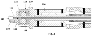
- the secondary rotary knob (118) has inner threads (122) which are engaged with the threaded wheel (120) through threads on its outer periphery.
- the threaded wheel (120) has two grooves (124) cut in longitudinal direction and engaged to the eccentric luer (126) through the groove (124).
- Two luer arms (128) of the eccentric luer (126) goes through the grooves (124).
- the threaded wheel (120) also has a narrow hole (121), on its cross-sectional surface (120) and the proximal end of the inner shaft (104) is connected with this narrow hole (121). Further, the eccentric luer (126) also has a guidewire port (114) that is connected with the guidewire shaft (103).
- the luer arms (128) functions as a guiderail for the threaded wheel (120) for its movement over the luer arms (128) in longitudinal direction.
- Rotary movement of the secondary rotary knob (118) causes movement of the threaded wheel (120) in longitudinal direction and the inner shaft (104) also moves accordingly in longitudinal direction.
- the guidewire shaft (103) is fixed to the eccentric luer (126) and remains stationary.
- Rotation of the secondary rotary knob (118) causes micro movement that better positioning of the implant and ensures detachment of the implant from the implant holder due to movement of the implant holder in longitudinal direction.
- the secondary rotary knob (118) comprises a safety pin (130) that engages with a safety slot (132) present on the cross-sectional of the secondary rotary knob (11) to restrict the unwanted movement of the secondary rotary knob (118).
- Numeral Reference Element Name 100 Catheter system for implant delivery 102 Capsule 101 Tip 104 Inner shaft 106 Catheter Shaft 103 Guidewire shaft 109 Implant holder 110 Handle 112 Handle housing 114 Guidewire Port 116 Primary rotary knob 118 Secondary rotary knob 120 Threaded wheel 121 Narrow hole 122 Internal threads 124 Groove 126 Eccentric luer 128 Luer arm 130 Safety pin 132 Safety slot 200 Proximal section 300 Middle section 400 Distal section
Landscapes
- Health & Medical Sciences (AREA)
- Engineering & Computer Science (AREA)
- Biomedical Technology (AREA)
- Life Sciences & Earth Sciences (AREA)
- Veterinary Medicine (AREA)
- Public Health (AREA)
- Heart & Thoracic Surgery (AREA)
- Cardiology (AREA)
- Animal Behavior & Ethology (AREA)
- General Health & Medical Sciences (AREA)
- Surgery (AREA)
- Oral & Maxillofacial Surgery (AREA)
- Transplantation (AREA)
- Vascular Medicine (AREA)
- Pathology (AREA)
- Nuclear Medicine, Radiotherapy & Molecular Imaging (AREA)
- Medical Informatics (AREA)
- Molecular Biology (AREA)
- Media Introduction/Drainage Providing Device (AREA)
Claims (13)
- Perkutaner Katheter zur Einbringung eines Implantats, umfassend:einen primären Drehknopf (116), der mit einem Katheterschaft (106) verbunden ist, um die Längsbewegung des Katheterschafts zu erleichtern;einen sekundären Drehknopf (118), der mit einem Innenschaft (104) verbunden ist, um die Längsbewegung des Innenschafts zu erleichtern, wobei der sekundäre Drehknopf mit einem Gewinderad (120) verbunden ist, und wobei das Gewinderad mit dem sekundären Drehknopf über ein Gewinde (122) in Eingriff steht;einen exzentrischen Luer (126) mit einer Führungsdrahtöffnung (114), die mit einem Führungsdrahtschaft (103) verbunden ist;mindestens einen Luer-Arm (128), der mit dem exzentrischen Luer (126) verbunden ist und in einem Abstand in radialer Richtung angeordnet ist, wobei der Luer-Arm parallel zur Längsachse durch die Mitte der Führungsdrahtöffnung (114) und den Führungsdrahtschaft (103) verläuft; undmindestens eine Nut (124), die in Längsrichtung in das Gewinderad (120) geschnitten ist und von mindestens einer Querschnittsfläche des Gewinderads zugänglich ist;wobei der Luer-Arm (128) durch die Nut (124) im Gewinderad (120) verläuft, und wobei sich das Gewinderad (120) bei einer Drehbewegung des sekundären Drehknopfes (118) in Längsrichtung über den Luer-Arm bewegt.
- Perkutaner Katheter zur Implantateinbringung nach Anspruch 1, wobei das Gewinderad (120) ein enges Loch (121) aufweist, das mit dem Innenschaft (104) verbunden ist.
- Perkutaner Katheter zur Einbringung von Implantaten nach Anspruch 2, wobei ein zusätzliches Element zwischen dem inneren Umfang des engen Lochs (121) und dem äußeren Umfang des Innenschafts (104) vorhanden ist.
- Perkutaner Katheter zur Einbringung von Implantaten nach Anspruch 1, wobei ein zusätzliches Element zwischen dem Innenumfang der Führungsdrahtöffnung (114) und dem Außenumfang des Führungsdrahtschafts (103) vorhanden ist.
- Perkutaner Katheter zur Implantateinbringung nach Anspruch 3 oder 4, wobei das zusätzliche Element mit verschiedenen Elementen durch Klebstoff, Dichtungsmittel, Leim, Gewinde, Schweißen oder eine Kombination davon verbunden ist.
- Perkutaner Katheter zur Implantateinbringung nach einem der Ansprüche 3 bis 5, wobei das Material des zusätzlichen Elements ausgewählt ist aus Metall, Nichtmetall, Legierung, Polymer, Holz, Naturfaser, Kunstfaser oder einer Kombination davon.
- Perkutaner Katheter zur Implantateinbringung nach einem der Ansprüche 3 bis 6, wobei die physikalische Form des zusätzlichen Elements ausgewählt ist aus einem hohlen kreisförmigen Ring, einem hohlen Zylinder, einem Ring, dessen innerer oder äußerer Umfang mindestens einen Winkel aufweist, einem Ring, dessen innerer oder äußerer Umfang ein Gewinde aufweist, einem Ring, dessen innerer oder äußerer Umfang mindestens einen Widerhaken aufweist, oder einer Kombination davon.
- Perkutaner Katheter zur Einbringung von Implantaten nach Anspruch 1, mit einem Sicherheitsmechanismus zum Sperren der Bewegung des sekundären Drehknopfes (118).
- Perkutaner Katheter zur Implantateinbringung nach Anspruch 9, wobei der Sicherheitsmechanismus einen Sicherheitsstift (130) und einen Sicherheitsschlitz (132) umfasst, und wobei der Sicherheitsstift und der Sicherheitsschlitz, wenn sie in Eingriff sind, die Bewegung des sekundären Drehknopfes (118) blockieren.
- Perkutaner Katheter zur Implantateinbringung nach Anspruch 8, wobei der Sicherheitsmechanismus ausgewählt ist aus dem Gewindetyp, dem Hakentyp, dem Sperrstifttyp, dem Schaltertyp (Ein/Aus-Typ), dem Klettverschlusstyp, dem magnetischen Typ oder einer Kombination davon.
- Perkutaner Katheter zur Implantateinbringung nach Anspruch 1, wobei das Implantat ausgewählt ist aus einem Stent, einer Klappe, einem Netz, einem Ballon, einem Pflaster, einer arzneimittelhaltigen Matrix, einem Shunt, einem Vena-Cava-Filter, einem Gefäßgraft, einem Stentgraft oder einer Kombination davon.
- Der perkutane Katheter zur Implantateinbringung nach Anspruch 1 umfasst einen Anzeigemechanismus, der das Ausmaß der Implantateinbringung anzeigt.
- Der perkutane Katheter zur Implantateinbringung nach Anspruch 1 umfasst mindestens eine röntgendichte Markierung auf der peripheren Oberfläche der Komponenten, ausgewählt aus einer Spitze, einer Kapsel, dem Führungsdrahtschaft (103) oder einer Kombination davon.
Applications Claiming Priority (2)
| Application Number | Priority Date | Filing Date | Title |
|---|---|---|---|
| IN202221028378 | 2022-05-17 | ||
| PCT/IN2022/050607 WO2023223333A1 (en) | 2022-05-17 | 2022-07-01 | Percutaneous catheter system for implant delivery |
Publications (2)
| Publication Number | Publication Date |
|---|---|
| EP4297702A1 EP4297702A1 (de) | 2024-01-03 |
| EP4297702B1 true EP4297702B1 (de) | 2024-05-29 |
Family
ID=88757683
Family Applications (1)
| Application Number | Title | Priority Date | Filing Date |
|---|---|---|---|
| EP22735759.7A Active EP4297702B1 (de) | 2022-05-17 | 2022-07-01 | Perkutanes kathetersystem zur implantateinführung |
Country Status (9)
| Country | Link |
|---|---|
| US (1) | US12268416B2 (de) |
| EP (1) | EP4297702B1 (de) |
| JP (1) | JP2025517585A (de) |
| KR (1) | KR20250052925A (de) |
| CN (1) | CN117425454A (de) |
| AU (1) | AU2022331909A1 (de) |
| BR (1) | BR112023004762A2 (de) |
| CA (1) | CA3192288A1 (de) |
| PL (1) | PL4297702T3 (de) |
Family Cites Families (2)
| Publication number | Priority date | Publication date | Assignee | Title |
|---|---|---|---|---|
| US8579963B2 (en) * | 2010-04-13 | 2013-11-12 | Medtronic, Inc. | Transcatheter prosthetic heart valve delivery device with stability tube and method |
| US10575951B2 (en) | 2015-08-26 | 2020-03-03 | Edwards Lifesciences Cardiaq Llc | Delivery device and methods of use for transapical delivery of replacement mitral valve |
-
2022
- 2022-07-01 AU AU2022331909A patent/AU2022331909A1/en active Pending
- 2022-07-01 EP EP22735759.7A patent/EP4297702B1/de active Active
- 2022-07-01 KR KR1020237007153A patent/KR20250052925A/ko active Pending
- 2022-07-01 PL PL22735759.7T patent/PL4297702T3/pl unknown
- 2022-07-01 CA CA3192288A patent/CA3192288A1/en active Pending
- 2022-07-01 JP JP2023514497A patent/JP2025517585A/ja active Pending
- 2022-07-01 BR BR112023004762A patent/BR112023004762A2/pt unknown
- 2022-07-01 CN CN202280005888.0A patent/CN117425454A/zh active Pending
- 2022-08-01 US US17/816,664 patent/US12268416B2/en active Active
Also Published As
| Publication number | Publication date |
|---|---|
| US12268416B2 (en) | 2025-04-08 |
| AU2022331909A1 (en) | 2023-12-07 |
| BR112023004762A2 (pt) | 2024-02-15 |
| CN117425454A (zh) | 2024-01-19 |
| EP4297702A1 (de) | 2024-01-03 |
| PL4297702T3 (pl) | 2024-09-23 |
| US20230371980A1 (en) | 2023-11-23 |
| CA3192288A1 (en) | 2023-11-17 |
| JP2025517585A (ja) | 2025-06-10 |
| KR20250052925A (ko) | 2025-04-21 |
Similar Documents
| Publication | Publication Date | Title |
|---|---|---|
| JP6829692B2 (ja) | 心臓弁プロテーゼ送出システム及び導入体シースにより心臓弁プロテーゼを送出するための方法 | |
| CA2598931C (en) | Multiple in vivo implant delivery device | |
| ES2983342T3 (es) | Implante para el tratamiento y/o la sustitución de una válvula cardíaca inflamada, trombosada o degenerada | |
| JP6470470B2 (ja) | 枢動運動によって反転するリーフレット送達システム | |
| JP6899452B2 (ja) | ステント送達システム | |
| US8403977B2 (en) | Self-orienting delivery system | |
| US20160000561A1 (en) | Transapical passive articulation delivery system design | |
| CN109475419A (zh) | 用于通过引导鞘和装载系统来递送心脏瓣膜假体的心脏瓣膜假体递送系统和方法 | |
| KR20150091336A (ko) | 심장 판막 대체용 인공 보철 시스템 | |
| JP6800155B2 (ja) | 慢性完全閉塞を有する身体血管における再進入のためのカテーテルシステムおよび方法 | |
| EP4297702B1 (de) | Perkutanes kathetersystem zur implantateinführung | |
| JP7490167B2 (ja) | 低速から高速の引き込みのための変換可能リビングヒンジを有するステント送達カテーテル | |
| WO2023223333A1 (en) | Percutaneous catheter system for implant delivery | |
| JP2022543988A (ja) | インプラント、送達装置、およびインプラントの送達方法 | |
| US12485028B2 (en) | Percutaneous implant delivery system | |
| CN119300789A (zh) | 具有带有可压缩区域的稳定管的递送装置 | |
| WO2023152755A1 (en) | Percutaneous implant delivery system | |
| RU2802268C2 (ru) | Имплантат, устройство доставки и способ доставки имплантата | |
| US20210282952A1 (en) | Endovascular catheter with delivery system separately assembled to stent graft system | |
| JP2025509004A (ja) | インプラント取り外し機構 | |
| HK40064814A (en) | Implant, delivery device and method of delivering an implant | |
| JP2022140037A (ja) | 展開物デリバリーシステム |
Legal Events
| Date | Code | Title | Description |
|---|---|---|---|
| STAA | Information on the status of an ep patent application or granted ep patent |
Free format text: STATUS: UNKNOWN |
|
| STAA | Information on the status of an ep patent application or granted ep patent |
Free format text: STATUS: THE INTERNATIONAL PUBLICATION HAS BEEN MADE |
|
| PUAI | Public reference made under article 153(3) epc to a published international application that has entered the european phase |
Free format text: ORIGINAL CODE: 0009012 |
|
| STAA | Information on the status of an ep patent application or granted ep patent |
Free format text: STATUS: REQUEST FOR EXAMINATION WAS MADE |
|
| GRAP | Despatch of communication of intention to grant a patent |
Free format text: ORIGINAL CODE: EPIDOSNIGR1 |
|
| STAA | Information on the status of an ep patent application or granted ep patent |
Free format text: STATUS: GRANT OF PATENT IS INTENDED |
|
| 17P | Request for examination filed |
Effective date: 20220714 |
|
| AK | Designated contracting states |
Kind code of ref document: A1 Designated state(s): AL AT BE BG CH CY CZ DE DK EE ES FI FR GB GR HR HU IE IS IT LI LT LU LV MC MK MT NL NO PL PT RO RS SE SI SK SM TR |
|
| DAV | Request for validation of the european patent (deleted) | ||
| DAX | Request for extension of the european patent (deleted) | ||
| INTG | Intention to grant announced |
Effective date: 20240103 |
|
| GRAS | Grant fee paid |
Free format text: ORIGINAL CODE: EPIDOSNIGR3 |
|
| GRAA | (expected) grant |
Free format text: ORIGINAL CODE: 0009210 |
|
| STAA | Information on the status of an ep patent application or granted ep patent |
Free format text: STATUS: THE PATENT HAS BEEN GRANTED |
|
| P01 | Opt-out of the competence of the unified patent court (upc) registered |
Effective date: 20240405 |
|
| AK | Designated contracting states |
Kind code of ref document: B1 Designated state(s): AL AT BE BG CH CY CZ DE DK EE ES FI FR GB GR HR HU IE IS IT LI LT LU LV MC MK MT NL NO PL PT RO RS SE SI SK SM TR |
|
| REG | Reference to a national code |
Ref country code: CH Ref legal event code: EP |
|
| REG | Reference to a national code |
Ref country code: IE Ref legal event code: FG4D |
|
| REG | Reference to a national code |
Ref country code: DE Ref legal event code: R096 Ref document number: 602022003709 Country of ref document: DE |
|
| REG | Reference to a national code |
Ref country code: NL Ref legal event code: FP |
|
| REG | Reference to a national code |
Ref country code: LT Ref legal event code: MG9D |
|
| PG25 | Lapsed in a contracting state [announced via postgrant information from national office to epo] |
Ref country code: IS Free format text: LAPSE BECAUSE OF FAILURE TO SUBMIT A TRANSLATION OF THE DESCRIPTION OR TO PAY THE FEE WITHIN THE PRESCRIBED TIME-LIMIT Effective date: 20240929 |
|
| PG25 | Lapsed in a contracting state [announced via postgrant information from national office to epo] |
Ref country code: BG Free format text: LAPSE BECAUSE OF FAILURE TO SUBMIT A TRANSLATION OF THE DESCRIPTION OR TO PAY THE FEE WITHIN THE PRESCRIBED TIME-LIMIT Effective date: 20240529 |
|
| PG25 | Lapsed in a contracting state [announced via postgrant information from national office to epo] |
Ref country code: HR Free format text: LAPSE BECAUSE OF FAILURE TO SUBMIT A TRANSLATION OF THE DESCRIPTION OR TO PAY THE FEE WITHIN THE PRESCRIBED TIME-LIMIT Effective date: 20240529 Ref country code: FI Free format text: LAPSE BECAUSE OF FAILURE TO SUBMIT A TRANSLATION OF THE DESCRIPTION OR TO PAY THE FEE WITHIN THE PRESCRIBED TIME-LIMIT Effective date: 20240529 |
|
| PG25 | Lapsed in a contracting state [announced via postgrant information from national office to epo] |
Ref country code: GR Free format text: LAPSE BECAUSE OF FAILURE TO SUBMIT A TRANSLATION OF THE DESCRIPTION OR TO PAY THE FEE WITHIN THE PRESCRIBED TIME-LIMIT Effective date: 20240830 |
|
| PG25 | Lapsed in a contracting state [announced via postgrant information from national office to epo] |
Ref country code: ES Free format text: LAPSE BECAUSE OF FAILURE TO SUBMIT A TRANSLATION OF THE DESCRIPTION OR TO PAY THE FEE WITHIN THE PRESCRIBED TIME-LIMIT Effective date: 20240529 |
|
| PG25 | Lapsed in a contracting state [announced via postgrant information from national office to epo] |
Ref country code: LV Free format text: LAPSE BECAUSE OF FAILURE TO SUBMIT A TRANSLATION OF THE DESCRIPTION OR TO PAY THE FEE WITHIN THE PRESCRIBED TIME-LIMIT Effective date: 20240529 |
|
| PG25 | Lapsed in a contracting state [announced via postgrant information from national office to epo] |
Ref country code: NO Free format text: LAPSE BECAUSE OF FAILURE TO SUBMIT A TRANSLATION OF THE DESCRIPTION OR TO PAY THE FEE WITHIN THE PRESCRIBED TIME-LIMIT Effective date: 20240829 Ref country code: LV Free format text: LAPSE BECAUSE OF FAILURE TO SUBMIT A TRANSLATION OF THE DESCRIPTION OR TO PAY THE FEE WITHIN THE PRESCRIBED TIME-LIMIT Effective date: 20240529 Ref country code: IS Free format text: LAPSE BECAUSE OF FAILURE TO SUBMIT A TRANSLATION OF THE DESCRIPTION OR TO PAY THE FEE WITHIN THE PRESCRIBED TIME-LIMIT Effective date: 20240929 Ref country code: HR Free format text: LAPSE BECAUSE OF FAILURE TO SUBMIT A TRANSLATION OF THE DESCRIPTION OR TO PAY THE FEE WITHIN THE PRESCRIBED TIME-LIMIT Effective date: 20240529 Ref country code: GR Free format text: LAPSE BECAUSE OF FAILURE TO SUBMIT A TRANSLATION OF THE DESCRIPTION OR TO PAY THE FEE WITHIN THE PRESCRIBED TIME-LIMIT Effective date: 20240830 Ref country code: FI Free format text: LAPSE BECAUSE OF FAILURE TO SUBMIT A TRANSLATION OF THE DESCRIPTION OR TO PAY THE FEE WITHIN THE PRESCRIBED TIME-LIMIT Effective date: 20240529 Ref country code: ES Free format text: LAPSE BECAUSE OF FAILURE TO SUBMIT A TRANSLATION OF THE DESCRIPTION OR TO PAY THE FEE WITHIN THE PRESCRIBED TIME-LIMIT Effective date: 20240529 Ref country code: BG Free format text: LAPSE BECAUSE OF FAILURE TO SUBMIT A TRANSLATION OF THE DESCRIPTION OR TO PAY THE FEE WITHIN THE PRESCRIBED TIME-LIMIT Effective date: 20240529 Ref country code: RS Free format text: LAPSE BECAUSE OF FAILURE TO SUBMIT A TRANSLATION OF THE DESCRIPTION OR TO PAY THE FEE WITHIN THE PRESCRIBED TIME-LIMIT Effective date: 20240829 |
|
| REG | Reference to a national code |
Ref country code: AT Ref legal event code: UEP Ref document number: 1690023 Country of ref document: AT Kind code of ref document: T Effective date: 20240529 |
|
| PG25 | Lapsed in a contracting state [announced via postgrant information from national office to epo] |
Ref country code: DK Free format text: LAPSE BECAUSE OF FAILURE TO SUBMIT A TRANSLATION OF THE DESCRIPTION OR TO PAY THE FEE WITHIN THE PRESCRIBED TIME-LIMIT Effective date: 20240529 |
|
| PG25 | Lapsed in a contracting state [announced via postgrant information from national office to epo] |
Ref country code: EE Free format text: LAPSE BECAUSE OF FAILURE TO SUBMIT A TRANSLATION OF THE DESCRIPTION OR TO PAY THE FEE WITHIN THE PRESCRIBED TIME-LIMIT Effective date: 20240529 |
|
| PG25 | Lapsed in a contracting state [announced via postgrant information from national office to epo] |
Ref country code: SK Free format text: LAPSE BECAUSE OF FAILURE TO SUBMIT A TRANSLATION OF THE DESCRIPTION OR TO PAY THE FEE WITHIN THE PRESCRIBED TIME-LIMIT Effective date: 20240529 Ref country code: RO Free format text: LAPSE BECAUSE OF FAILURE TO SUBMIT A TRANSLATION OF THE DESCRIPTION OR TO PAY THE FEE WITHIN THE PRESCRIBED TIME-LIMIT Effective date: 20240529 |
|
| PG25 | Lapsed in a contracting state [announced via postgrant information from national office to epo] |
Ref country code: SM Free format text: LAPSE BECAUSE OF FAILURE TO SUBMIT A TRANSLATION OF THE DESCRIPTION OR TO PAY THE FEE WITHIN THE PRESCRIBED TIME-LIMIT Effective date: 20240529 |
|
| PG25 | Lapsed in a contracting state [announced via postgrant information from national office to epo] |
Ref country code: SM Free format text: LAPSE BECAUSE OF FAILURE TO SUBMIT A TRANSLATION OF THE DESCRIPTION OR TO PAY THE FEE WITHIN THE PRESCRIBED TIME-LIMIT Effective date: 20240529 Ref country code: SK Free format text: LAPSE BECAUSE OF FAILURE TO SUBMIT A TRANSLATION OF THE DESCRIPTION OR TO PAY THE FEE WITHIN THE PRESCRIBED TIME-LIMIT Effective date: 20240529 Ref country code: RO Free format text: LAPSE BECAUSE OF FAILURE TO SUBMIT A TRANSLATION OF THE DESCRIPTION OR TO PAY THE FEE WITHIN THE PRESCRIBED TIME-LIMIT Effective date: 20240529 Ref country code: EE Free format text: LAPSE BECAUSE OF FAILURE TO SUBMIT A TRANSLATION OF THE DESCRIPTION OR TO PAY THE FEE WITHIN THE PRESCRIBED TIME-LIMIT Effective date: 20240529 Ref country code: DK Free format text: LAPSE BECAUSE OF FAILURE TO SUBMIT A TRANSLATION OF THE DESCRIPTION OR TO PAY THE FEE WITHIN THE PRESCRIBED TIME-LIMIT Effective date: 20240529 |
|
| PG25 | Lapsed in a contracting state [announced via postgrant information from national office to epo] |
Ref country code: MC Free format text: LAPSE BECAUSE OF FAILURE TO SUBMIT A TRANSLATION OF THE DESCRIPTION OR TO PAY THE FEE WITHIN THE PRESCRIBED TIME-LIMIT Effective date: 20240529 |
|
| REG | Reference to a national code |
Ref country code: DE Ref legal event code: R097 Ref document number: 602022003709 Country of ref document: DE |
|
| PG25 | Lapsed in a contracting state [announced via postgrant information from national office to epo] |
Ref country code: LU Free format text: LAPSE BECAUSE OF NON-PAYMENT OF DUE FEES Effective date: 20240701 |
|
| PG25 | Lapsed in a contracting state [announced via postgrant information from national office to epo] |
Ref country code: LU Free format text: LAPSE BECAUSE OF NON-PAYMENT OF DUE FEES Effective date: 20240701 |
|
| PLBE | No opposition filed within time limit |
Free format text: ORIGINAL CODE: 0009261 |
|
| STAA | Information on the status of an ep patent application or granted ep patent |
Free format text: STATUS: NO OPPOSITION FILED WITHIN TIME LIMIT |
|
| PG25 | Lapsed in a contracting state [announced via postgrant information from national office to epo] |
Ref country code: SI Free format text: LAPSE BECAUSE OF FAILURE TO SUBMIT A TRANSLATION OF THE DESCRIPTION OR TO PAY THE FEE WITHIN THE PRESCRIBED TIME-LIMIT Effective date: 20240529 Ref country code: BE Free format text: LAPSE BECAUSE OF NON-PAYMENT OF DUE FEES Effective date: 20240731 |
|
| 26N | No opposition filed |
Effective date: 20250303 |
|
| REG | Reference to a national code |
Ref country code: BE Ref legal event code: MM Effective date: 20240731 |
|
| PGFP | Annual fee paid to national office [announced via postgrant information from national office to epo] |
Ref country code: PL Payment date: 20250624 Year of fee payment: 4 |
|
| PGFP | Annual fee paid to national office [announced via postgrant information from national office to epo] |
Ref country code: NL Payment date: 20250630 Year of fee payment: 4 |
|
| PGFP | Annual fee paid to national office [announced via postgrant information from national office to epo] |
Ref country code: FR Payment date: 20250616 Year of fee payment: 4 |
|
| PGFP | Annual fee paid to national office [announced via postgrant information from national office to epo] |
Ref country code: TR Payment date: 20250627 Year of fee payment: 4 |
|
| PGFP | Annual fee paid to national office [announced via postgrant information from national office to epo] |
Ref country code: IE Payment date: 20250620 Year of fee payment: 4 |
|
| PG25 | Lapsed in a contracting state [announced via postgrant information from national office to epo] |
Ref country code: SE Free format text: LAPSE BECAUSE OF FAILURE TO SUBMIT A TRANSLATION OF THE DESCRIPTION OR TO PAY THE FEE WITHIN THE PRESCRIBED TIME-LIMIT Effective date: 20240529 |
|
| PGFP | Annual fee paid to national office [announced via postgrant information from national office to epo] |
Ref country code: DE Payment date: 20250711 Year of fee payment: 4 |
|
| PGFP | Annual fee paid to national office [announced via postgrant information from national office to epo] |
Ref country code: IT Payment date: 20250731 Year of fee payment: 4 |
|
| PGFP | Annual fee paid to national office [announced via postgrant information from national office to epo] |
Ref country code: AT Payment date: 20251020 Year of fee payment: 4 |
|
| PGFP | Annual fee paid to national office [announced via postgrant information from national office to epo] |
Ref country code: CH Payment date: 20250801 Year of fee payment: 4 |
|
| PGFP | Annual fee paid to national office [announced via postgrant information from national office to epo] |
Ref country code: CZ Payment date: 20250630 Year of fee payment: 4 |
|
| PG25 | Lapsed in a contracting state [announced via postgrant information from national office to epo] |
Ref country code: CY Free format text: LAPSE BECAUSE OF FAILURE TO SUBMIT A TRANSLATION OF THE DESCRIPTION OR TO PAY THE FEE WITHIN THE PRESCRIBED TIME-LIMIT; INVALID AB INITIO Effective date: 20220701 |
|
| REG | Reference to a national code |
Ref country code: CH Ref legal event code: R18 Free format text: ST27 STATUS EVENT CODE: U-0-0-R10-R18 (AS PROVIDED BY THE NATIONAL OFFICE) Effective date: 20260106 |