EP4297489A2 - Verfahren zur übertragung von ap-fehlercodes über ble-werbung - Google Patents
Verfahren zur übertragung von ap-fehlercodes über ble-werbung Download PDFInfo
- Publication number
- EP4297489A2 EP4297489A2 EP23205320.7A EP23205320A EP4297489A2 EP 4297489 A2 EP4297489 A2 EP 4297489A2 EP 23205320 A EP23205320 A EP 23205320A EP 4297489 A2 EP4297489 A2 EP 4297489A2
- Authority
- EP
- European Patent Office
- Prior art keywords
- network
- message
- access point
- isolated
- communication channel
- Prior art date
- Legal status (The legal status is an assumption and is not a legal conclusion. Google has not performed a legal analysis and makes no representation as to the accuracy of the status listed.)
- Pending
Links
Images


Classifications
-
- H—ELECTRICITY
- H04—ELECTRIC COMMUNICATION TECHNIQUE
- H04W—WIRELESS COMMUNICATION NETWORKS
- H04W4/00—Services specially adapted for wireless communication networks; Facilities therefor
- H04W4/06—Selective distribution of broadcast services, e.g. multimedia broadcast multicast service [MBMS]; Services to user groups; One-way selective calling services
-
- H—ELECTRICITY
- H04—ELECTRIC COMMUNICATION TECHNIQUE
- H04L—TRANSMISSION OF DIGITAL INFORMATION, e.g. TELEGRAPHIC COMMUNICATION
- H04L41/00—Arrangements for maintenance, administration or management of data switching networks, e.g. of packet switching networks
- H04L41/06—Management of faults, events, alarms or notifications
- H04L41/0677—Localisation of faults
-
- H—ELECTRICITY
- H04—ELECTRIC COMMUNICATION TECHNIQUE
- H04L—TRANSMISSION OF DIGITAL INFORMATION, e.g. TELEGRAPHIC COMMUNICATION
- H04L41/00—Arrangements for maintenance, administration or management of data switching networks, e.g. of packet switching networks
- H04L41/06—Management of faults, events, alarms or notifications
- H04L41/0631—Management of faults, events, alarms or notifications using root cause analysis; using analysis of correlation between notifications, alarms or events based on decision criteria, e.g. hierarchy, tree or time analysis
-
- H—ELECTRICITY
- H04—ELECTRIC COMMUNICATION TECHNIQUE
- H04L—TRANSMISSION OF DIGITAL INFORMATION, e.g. TELEGRAPHIC COMMUNICATION
- H04L41/00—Arrangements for maintenance, administration or management of data switching networks, e.g. of packet switching networks
- H04L41/06—Management of faults, events, alarms or notifications
- H04L41/0654—Management of faults, events, alarms or notifications using network fault recovery
-
- H—ELECTRICITY
- H04—ELECTRIC COMMUNICATION TECHNIQUE
- H04L—TRANSMISSION OF DIGITAL INFORMATION, e.g. TELEGRAPHIC COMMUNICATION
- H04L41/00—Arrangements for maintenance, administration or management of data switching networks, e.g. of packet switching networks
- H04L41/06—Management of faults, events, alarms or notifications
- H04L41/069—Management of faults, events, alarms or notifications using logs of notifications; Post-processing of notifications
-
- H—ELECTRICITY
- H04—ELECTRIC COMMUNICATION TECHNIQUE
- H04L—TRANSMISSION OF DIGITAL INFORMATION, e.g. TELEGRAPHIC COMMUNICATION
- H04L43/00—Arrangements for monitoring or testing data switching networks
- H04L43/08—Monitoring or testing based on specific metrics, e.g. QoS, energy consumption or environmental parameters
- H04L43/0805—Monitoring or testing based on specific metrics, e.g. QoS, energy consumption or environmental parameters by checking availability
- H04L43/0811—Monitoring or testing based on specific metrics, e.g. QoS, energy consumption or environmental parameters by checking availability by checking connectivity
-
- H—ELECTRICITY
- H04—ELECTRIC COMMUNICATION TECHNIQUE
- H04L—TRANSMISSION OF DIGITAL INFORMATION, e.g. TELEGRAPHIC COMMUNICATION
- H04L67/00—Network arrangements or protocols for supporting network services or applications
- H04L67/01—Protocols
- H04L67/10—Protocols in which an application is distributed across nodes in the network
-
- H—ELECTRICITY
- H04—ELECTRIC COMMUNICATION TECHNIQUE
- H04L—TRANSMISSION OF DIGITAL INFORMATION, e.g. TELEGRAPHIC COMMUNICATION
- H04L69/00—Network arrangements, protocols or services independent of the application payload and not provided for in the other groups of this subclass
- H04L69/40—Network arrangements, protocols or services independent of the application payload and not provided for in the other groups of this subclass for recovering from a failure of a protocol instance or entity, e.g. service redundancy protocols, protocol state redundancy or protocol service redirection
-
- H—ELECTRICITY
- H04—ELECTRIC COMMUNICATION TECHNIQUE
- H04W—WIRELESS COMMUNICATION NETWORKS
- H04W24/00—Supervisory, monitoring or testing arrangements
- H04W24/04—Arrangements for maintaining operational condition
-
- H—ELECTRICITY
- H04—ELECTRIC COMMUNICATION TECHNIQUE
- H04W—WIRELESS COMMUNICATION NETWORKS
- H04W4/00—Services specially adapted for wireless communication networks; Facilities therefor
- H04W4/50—Service provisioning or reconfiguring
-
- H—ELECTRICITY
- H04—ELECTRIC COMMUNICATION TECHNIQUE
- H04W—WIRELESS COMMUNICATION NETWORKS
- H04W4/00—Services specially adapted for wireless communication networks; Facilities therefor
- H04W4/80—Services using short range communication, e.g. near-field communication [NFC], radio-frequency identification [RFID] or low energy communication
-
- H—ELECTRICITY
- H04—ELECTRIC COMMUNICATION TECHNIQUE
- H04W—WIRELESS COMMUNICATION NETWORKS
- H04W40/00—Communication routing or communication path finding
- H04W40/24—Connectivity information management, e.g. connectivity discovery or connectivity update
- H04W40/244—Connectivity information management, e.g. connectivity discovery or connectivity update using a network of reference devices, e.g. beaconing
-
- H—ELECTRICITY
- H04—ELECTRIC COMMUNICATION TECHNIQUE
- H04W—WIRELESS COMMUNICATION NETWORKS
- H04W48/00—Access restriction; Network selection; Access point selection
- H04W48/08—Access restriction or access information delivery, e.g. discovery data delivery
- H04W48/12—Access restriction or access information delivery, e.g. discovery data delivery using downlink control channel
-
- H—ELECTRICITY
- H04—ELECTRIC COMMUNICATION TECHNIQUE
- H04L—TRANSMISSION OF DIGITAL INFORMATION, e.g. TELEGRAPHIC COMMUNICATION
- H04L41/00—Arrangements for maintenance, administration or management of data switching networks, e.g. of packet switching networks
- H04L41/06—Management of faults, events, alarms or notifications
- H04L41/0686—Additional information in the notification, e.g. enhancement of specific meta-data
Definitions
- the present disclosure relates to monitoring wireless communications systems and, more particularly but not exclusively, to methods and/or apparatus for determining a root cause of a network node, such as an access point (AP), not being able to connect to the backhaul network.
- a network node such as an access point (AP)
- AP access point
- Such a network node may be referred to as an isolated node.
- An Access Point is a networking hardware device that allows a Wi-Fi device to connect to a wireless and/or wired network via Wi-Fi.
- the AP usually connects to a router (via a wired network) and is typically a standalone device, but the AP can also be an integral component of the router itself. While examples will be discussed in relation to the isolated node being an AP, it is to be appreciated that the technology described herein can be used with any networking device(s).
- an AP When for any reason an AP fails to connect to a wired network, all clients that rely on that AP for their communications lose their ability to communicate with devices attached to the wired network. Because of the criticality of the connectivity between the AP and the wired network, most network management/monitoring systems monitor the connectivity of the AP using keep-alive messages, or other similar techniques. If a network monitoring system detects a loss of connectivity between an AP and the wired network, an IT technician is informed via, for example, an alert message and is tasked with debugging and repairing the issue. Similarly, the loss of connectivity of an AP to the wired network affects all mobile device wireless terminals (WT) associated with the specific AP. As such, the loss of connectivity may be detected by the WT and reported to an IT technician by any of the WT users.
- WT mobile device wireless terminals
- Connectivity of an AP to a wired network relies on multiple functions/services that the wired network facilitates. These services include, but are not limited to, authentication, authorization, accounting, IP address resolution, etc. Failure of an AP to connect to a wired network could be a result of a failure in any one of these services/functions. Often the abovementioned services are provided by equipment from different vendors or from a vendor different than the manufacturer of the Wi-Fi AP. To accelerate the debugging process, it can be beneficial to obtain information about the failure from the point of view of the isolated AP.
- the Network Management System cannot probe the isolated AP and request the AP to send debugging information the AP may have such as: error logs, message logs, connectivity logs, etc., and in general any information related to its operation (and/or failures).
- Debugging information can be, and usually is, collected from the isolated AP by connecting a data collection device, such as a PC/laptop, and downloading the debugging information from the AP to the data collection device.
- a data collection device such as a PC/laptop
- Many companies consolidated their field support operations, and consequently, the field support centers may be located in a remote site other than the site where the isolated AP is located.
- companies devised a simple LED based method for obtaining rudimentary debugging information from an AP.
- an isolated AP When an isolated AP detects failure such as inability to connect to the backhaul network (the cloud), it analyzes the internal debugging information (including finding pattern of abnormal message flows, timer expiration when awaiting a reply message from another server, etc.), formats a message to facilitate the debugging process and conveys the debugging information to nearby observers by blinking a specific sequence of LEDs.
- the sequence may, and often does, use LEDs with different colors, change the duration of the LED blinking, change the frequency of the blinking, etc.
- Similar status messages may be conveyed to a nearby observer about normal operation of the AP. For example, a blue LED always on may convey a message that at least one WT is associated with the AP, a green LED always on may convey a message that no error was detected, etc.
- debugging requires as onsite observer available to spend time with a remote technician in support of the debugging process.
- the present approaches may provide a system that can facilitate conveying debugging information from an isolated AP, that cannot connect with the network/cloud, to IT personnel without requiring any onsite support.
- beacons were installed in an area of interest. Mobile devices, in the vicinity of the beacons, measure the (Received Signal Strength Indicator) RSSI of signals from each beacon and report it to a location engine over a Wi-Fi network. The location engine then uses the RSSI measurements from each terminal to determine the location of each mobile wireless terminal.
- Received Signal Strength Indicator Received Signal Strength Indicator
- the beacon signal is a Bluetooth ® Low Energy (BLE) signal, however, those skilled in the art will recognize that other beacons at other frequencies and/or power and/or protocols are covered by the described technology.
- BLE Bluetooth ® Low Energy
- this combined AP device utilizes a first frequency to establish a Wi-Fi communication with a WT and second frequency, e.g., BLE, to enable the WT location estimations.
- a mobile device e.g., a WT, receives the beacon signal from a plurality of beacons. Each beacon signal is broadcast periodically, e.g., once per second, and carries the ID of the specific beacon. The mobile device measures the RSSI received from each beacon and reports the RSSI back to the location engine. Reporting of the RSSI can be, and often is, done over the Wi-Fi network. In accordance with some aspects, the RSSI reporting can be done over BLE, or any other available network connectivity.
- a network monitoring server may, and often do, send a periodic status and/or keep-alive message to the monitoring server(s).
- the component sends an error message to the monitoring service informing the monitoring service of the issue(s).
- the error message may contain additional information, e.g., internal log information, which can help a technician in the process of determining the root cause of the fault.
- the monitoring server can still detect the fault by detecting the absence of the keep-alive message. However, in this scenario, the monitoring server cannot access the logging information or any other status information in the isolated AP.
- an IT technician may need to be dispatched to the site where the fault occurred. Once on-site, the technician may connect to the AP via a local wireless connection, or via a wired connection, and download the information logged at the isolated AP. For companies that do not have a technician onsite, the process of collecting the logged information from a faulty isolated AP may be a costly proposition.
- equipment manufacturers use a simple LED based method for obtaining rudimentary debugging information from an AP.
- the AP can analyze the internal debugging information, format a message to facilitate the debugging process and convey or communicate the debugging information to nearby observers by blinking a specific sequence of LED(s).
- the sequence may, and often does, use LEDs with different colors, change the duration of the LED blinking, change the frequency of the blinking, etc.
- status messages may be conveyed to a nearby observer about normal operation of the AP.
- the observer may, and often does, record the LED blinking sequence and convey it to the IT maintenance team. For example, the observer may capture the LED blinking sequence by recording a short video clip of the blinking LED(s) and attach it to an IT fault reporting ticket, or just send it to the IT technician.
- the LED blinking sequence can, and often does, utilize a single LED.
- An example blinking message can, and often does, start with a single blink followed by a short pause and a sequence of consecutive blinks.
- the single blink marks the start of a message and the number of consecutive blinks denotes an error code number. For example, 1 blink followed by 2 blinks corresponds to error code 2 which signifies that the AP cannot reach the cloud.
- One blink followed by a pause and consecutive six blinks corresponds to error code 6 which signifies that mutual authentication between the AP and the cloud is failing.
- the LED sequence may, and often does, utilize multiple LEDs with different colors, or a single LED capable of emitting different colors.
- the specifics of the encoding the error code into a sequence of blinking LED(s) is not essential for the disclosed technology.
- the error reporting module examines the internal log and creates a message that could facilitate identifying the root cause of the fault.
- the message contains the error code that the LED(s) are blinking.
- the ERM creates a comprehensive message which would have been more difficult to capture by simply observing the LED.
- the ERM may create a message that includes the sequence of messages between the AP and the backhaul network (the cloud) leading to denial of associating the AP with the backhaul network.
- the specifics of the message are not essential for this disclosure and the technology discussed herein can work with any message that automatically notifies the monitoring server that the AP cannot perform some function, such as associate with the network, and provide information that facilitates determining the root cause of the fault.
- the monitoring service may, and often does, automatically initiate a recovery mechanism.
- the ERM forms a message (or selects one of multiple canned messages) to be sent to the monitoring server. Since the isolated AP cannot associate with the network, the message cannot be sent via the normal backhaul link, which usually utilizes a wired connection to a gateway, a switch, or to a router.
- the backhaul link may be a wireless link such as a radio-based link, a fiber optic link, or any other communications means.
- an example aspect utilizes the beacon signal.
- this beacon signal can be part of the location system.
- the message that the ERM formed is passed to the broadcast beacon, e.g., the BLE location beacon.
- the beacon transmitter broadcasts the message from the ERM.
- the beacon system of each AP includes a transmitter and a receiver capable of listening for beacon messages from neighboring APs.
- an AP receives a normal location beacon message from a neighboring AP, which includes the ID of the beacon, the receiver ignores this message.
- the receiving AP first determines if the AP has connectivity to the cloud. If the AP does, then the AP utilizes its backhaul connectivity and forwards the received message from the isolated AP to the monitoring server on behalf of the isolated AP.
- the receiving AP If the receiving AP cannot connect to the cloud or network, it cannot forward directly the received message to the monitoring server. In accordance with one aspect, the receiving AP simply ignores the received message from the neighboring AP in this scenario. However, since the receiving AP does not have a backhaul communication link, its ERM can, and often does, form its own error message and broadcast the error message using its own location beacon.
- the ERM of the receiving AP forms a message that includes the ID(s) of the respective neighboring isolated AP(s) which also cannot connect to the cloud/network.
- This enhanced status message is then transmitted using the location beacon of the receiving AP and helps the monitoring server assess the scope of the issue.
- the neighboring AP forwards the error and/or debugging information to the network monitoring server to which it usually sends its own status and/or keep alive.
- the receiving device may be a mobile device such as a mobile phone whose location is tracked using the location server.
- the mobile device is configured to send RSSI information from neighboring beacons to a location server.
- the mobile device may, and often does, forward the error message to the IP address of the location server the mobile device knows, and the location server in turn recognizes the message as an error message and forwards it to the network management server and more specifically to the network monitoring system which is part of the broader network management system.
- an isolated device e.g., BLE broadcast
- the mobile device may, and often does, forward the error message to the IP address of the location server the mobile device knows, and the location server in turn recognizes the message as an error message and forwards it to the network management server and more specifically to the network monitoring system which is part of the broader network management system.
- APs utilize different backhaul channels and employ different servers to attach to the network.
- the system assumes that at least one of the APs is still able to establish a connection to the cloud and facilitate the forwarding of error broadcast messages from an isolated neighboring APs to the monitoring server.
- other devices such as mobile devices, WTs, etc., that receive the broadcast error message may be used to convey the error message to the network monitoring server.
- the monitoring server When the monitoring server receives an error and/or debugging message from the ERM of an isolated AP that cannot connect to the cloud, the monitoring server analyzes the message and invokes a corrective action.
- Illustrative corrective actions include, but are not limited to, alerting an IT technician about the issue, displaying detailed information about the root cause of the issue on a screen of an IT technician, restarting a Dynamic Host Control Protocol (DHCP) server, restarting an AP, restarting a router, restarting a switch, restarting a gateway (GW), restarting an authentication, authorization, and accounting (AAA) server, etc.
- DHCP Dynamic Host Control Protocol
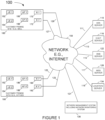
- Example system 100 includes a plurality of access points (AP1 166, ..., AP X 168, AP 1' 186, ..., AP X' 188), a plurality of Authentication, Authorization and Accounting (AAA) servers (only one AAA server 110 is shown), a plurality of Dynamic Host Configuration Protocol (DHCP) servers (only one DHCP server 116 is shown), a plurality of Domain Name System (DNS) severs (only one DNS server 122 is shown), a plurality of Web servers (only one Web server 128 is shown), a plurality of Location servers (only one Location server 134 is shown), and a network management system (NMS) 136, e.g., an access point management system, which are coupled together via network 150, e.g., the Internet and/or an enterprise intranet and/or a LAN and/or WAN.
- AAA Authentication, Authorization and Accounting
- AAA Authentication, Authorization and Accounting
- DHCP Dynamic Hos
- Network communications links (127, 129,123, and 125,) couple the access points (AP1 166, AP X 168, AP 1' 186, AP X' 188), respectively, to network 150 using gateways or routers (R1 170, RY 172, R1' 190, and RY' 192) respectively.
- Network communications link 111 couples the AAA servers (only one AAA server 110 is shown) to network 150.
- Network communications link 113 couples the DHCP servers (only one DHCP server 116 is shown) to network 150.
- Network communications link 115 couple the DNS servers (only one DNS server 122 is shown) to network 150.
- Network communications link 117 couple the Web servers (only one Web server 128 is shown) to network 150.
- Network communications link 119 couple the Location servers (only one Location server 134 is shown) to network 150.
- the example system 100 further includes a plurality of user equipment devices (UE 1 162, ..., UE Z 164, UE 1' 182, ..., UE Z' 184). At least some of the UEs (162, 164, 182, 184) are wireless mobile devices (such as a smartphone) which may move throughout system 100.
- UE 1 162, ..., UE Z 164, UE 1' 182, ..., UE Z' 184 are wireless mobile devices (such as a smartphone) which may move throughout system 100.
- sets of access points are located at different customer premise sites.
- Customer premise site 1 160 e.g., a mall, includes access points (AP 1 166, ..., AP X 168).
- Customer premise site 2 180 e.g., an office, includes access points (AP 1' 186, ..., AP X' 188).
- UEs UE 1 162, ..., UE Z 164 are currently located at customer premise site 1 160;
- UEs (UE 1' 182, ..., UE Z' 184) are currently located at customer premise site 2 180.
- access points AP1, AP X, AP1', and AP X' also broadcast beacon signals.
- Wireless terminals UE 1, UE Z, UE 1', and UE Z' receive the beacon signals, measure the RSSI and report the RSSI via the Wi-Fi link and routers R1, RY, R1', and RY', to the location server 134. The measured RSSIs are then used by the location servers to calculate the location of the respective wireless mobile terminals. Beacon signals from any AP are often received by a neighboring AP and ignored.
- Figure 2 illustrates an example access point 200 (e.g., access points AP 1 166, ..., APX 168, AP 1' 186, ..., APX' 188).
- access point 200 e.g., access points AP 1 166, ..., APX 168, AP 1' 186, ..., APX' 188.
- Access point 200 includes wired interfaces 230, wireless interfaces 236, 242, a processor 206, e.g., a CPU, a memory 212, and an assembly of modules 208, e.g., assembly of hardware modules, e.g., assembly of circuits, coupled together via a bus 209 over which the various elements may interchange data and information.
- Wired interface 230 includes receiver 232 and transmitter 234. The wired interface couples the access point 200 to a network and/or the Internet such as 150 of Figure 1 via routers such as R1, RY, R1', and RY'.
- First wireless interfaces 236 may support a Wi-Fi interface, e.g.
- IEEE 802.11 interface includes receiver 238 coupled to receive antenna 239, via which the access point may receive wireless signals from communications devices, e.g., wireless terminals, and transmitter 240 coupled to transmit antenna 241 via which the access point may transmit wireless signals to communications devices, e.g., wireless terminals.
- Second wireless interface 242 may support Bluetooth ® communications which includes receiver 244 coupled to receive antenna 245, via which the access point may receive wireless signals from neighboring communications devices (e.g., other access points, wireless terminals, etc.) and transmitter 246 coupled to transmit antenna 247 via which the access point may transmit wireless signals (e.g., beacon signals, broadcast messages, etc.) to communications devices, (e.g., other access points, wireless terminals, etc.).
- neighboring communications devices e.g., other access points, wireless terminals, etc.
- transmitter 246 coupled to transmit antenna 247 via which the access point may transmit wireless signals (e.g., beacon signals, broadcast messages, etc.) to communications devices, (e.g., other access points, wireless terminals, etc.).
- Memory 212 includes routines 214 and data/information 216.
- Routines 214 include assembly of modules 218, e.g., an assembly of software modules, and Application Programming Interfaces (APIs) 220.
- Data/information 216 includes software configured to store and/or obtain configuration information 222, log information 224 and manage error reporting for the ERM 226 which monitors connectivity of the AP to the cloud 150.
- the AP Upon detecting that the AP cannot connect to the cloud, the AP, and in particular the ERM 226, formulates a message to be sent to the monitoring system 136 of Figure 1 . The message is then conveyed to a beacon and broadcast via beacon transmitter 246 to neighboring APs.
- the broadcast error message from an isolated AP, which was disconnected from the network 150, is received by a wireless receiver 244 in a neighboring AP(s). Assuming that the neighboring AP has connectivity to the cloud 150, this neighboring AP conveys the received error message to the network management system 136 of Figure 1 .
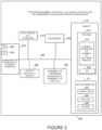
- Figure 3 illustrates an example network management and monitoring system 300, e.g., a wireless system monitoring server, an access point management node, or the like,.
- the network monitoring system 300 of Figure 3 is network management system (NMS) 136 of Figure 1 .
- Network management system 300 includes a communications interface 330, e.g., an Ethernet interface, a processor 306, an output device 308, e.g., display, printer, etc., an input device 310, e.g., keyboard, keypad, touch screen, mouse, etc., a memory 312 and an assembly of modules 340, e.g., assembly of hardware modules, e.g., assembly of circuits, coupled together via a bus 309 over which the various elements may interchange data and information.
- a communications interface 330 e.g., an Ethernet interface
- a processor 306 an output device 308, e.g., display, printer, etc.
- an input device 310 e.g., keyboard, keypad, touch screen, mouse, etc
- Communications interface 330 couples the network monitoring system 300 to a network and/or the Internet 150 of Figure 1 .
- Communications interface 330 includes a receiver 332 via which the network monitoring system can receive data and information, e.g., including service related information, (e.g., keep alive messages from various APs, error messages from various network components of network 100, etc.), and a transmitter 334, via which the network monitoring system 300 can send data and information, e.g., including configuration information and instructions, e.g., instructions to access points to restart, change transmission power, add an SSID, instruction to cloud servers (e.g., AAA server, DHCP server, DNS server, etc.) instructing them to take corrective actions such as update their software, restart the server, etc.
- the network management system can use the output module 308 to display status of various network components, error messages, debugging related information, etc.
- Memory 312 includes routines 314 and data/information 317.
- Routines 314 include assembly of modules 318, e.g., an assembly of software modules and/or instructions and Application Programming Interfaces (APIs) 320.
- Data/information 317 includes configuration information 322 as well as software for the operation of the component status and error message analyzer 324 and collection of remedial actions 326 to be taken when the network management system determines that an AP cannot connect to the cloud 150.
- the remedial actions may be configured by the system administrator based on past experience(s).
- the remedial actions can be automatically invoked as soon as the network management server determines the root cause of the network fault. This root cause can be determined by detecting a loss of keep alive message from a specific AP and/or by analyzing error message(s) from another AP which was broadcast using the beacon signal.
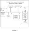
- Figure 4 illustrates an example node 400, e.g., AAA server, DHCP server, DNS server, Web server, Location server, etc.
- node 400 of Figure 4 is server 110, 116, 122, 128, 134, of Figure 1 .
- Node 400 includes a communications interface 402, e.g., an Ethernet interface, a processor 406, an output device 408, e.g., display, printer, etc., an input device 410, e.g., keyboard, keypad, touch screen, mouse, etc., a memory 412 and an assembly of modules 416, e.g., assembly of hardware modules, e.g., assembly of circuits, coupled together via a bus 409 over which the various elements may interchange data and information.
- a communications interface 402 e.g., an Ethernet interface
- a processor 406 an output device 408, e.g., display, printer, etc.
- an input device 410 e.g., keyboard, keypad, touch screen, mouse, etc.
- Communications interface 402 couples the network node 400 to a network and/or the Internet.
- Communications interface 402 includes a receiver 420 via which the node can receive data and information, (e.g., including operation related information, e.g., registration request, AAA services, DHCP requests, RSSI information, Simple Notification Service (SNS) look-ups, and Web page requests, etc.), and a transmitter 422, via which the node server 400 can send data and information, (e.g., including configuration information, authentication information, web page data, etc.).
- data and information e.g., including operation related information, e.g., registration request, AAA services, DHCP requests, RSSI information, Simple Notification Service (SNS) look-ups, and Web page requests, etc.
- SNS Simple Notification Service
- Memory 412 includes routines 428 and data/information 430.
- Routines 428 include assembly of modules 432, e.g., an assembly of software modules and data/information 430.
- Figure 5 illustrates an example client such as UE 500 (e.g., user equipment UE 1 162, ..., UE Z 164, UE 1' 182, ..., UE Z' 184).
- UE 500 e.g., user equipment UE 1 162, ..., UE Z 164, UE 1' 182, ..., UE Z' 184.
- LTE 500 includes optional wired interfaces 502, wireless interfaces 504, a processor 506, e.g., a CPU, a memory 512, and an assembly of modules 516, e.g., assembly of hardware modules, e.g., assembly of circuits, coupled together via a bus 509 over which the various elements may interchange data and information.
- Wired interface 502 includes receiver 520 and transmitter 522. The wired interface couples the LTE 500 to a network and/or the Internet 150 of Figure 1 .
- the wireless interface 504 includes cellular interface 524, first wireless interface 526, e.g., 802.11 WiFi interface, and a second wireless interface 528, e.g., Bluetooth ® interface.
- the cellular interface 524 includes a receiver 532 coupled to receiver antenna 533 via which the access point may receive wireless signals from access points, e.g., AP 1 166, ..., APX 168, AP 1' 186, ..., APX' 188, and transmitter 534 coupled to transmit antenna 535 via which the access point may transmit wireless signals to APs, e.g., AP 1 166, ..., APX 168, AP 1' 186, ..., APX' 188.
- access points e.g., AP 1 166, ..., APX 168, AP 1' 186, ..., APX' 188.
- First wireless interface 526 may support a Wi-Fi interface, e.g. 802.11 interface, and includes receiver 536 coupled to receive antenna 537, via which the UE may receive wireless signals from communications devices, e.g., APs, and transmitter 538 coupled to transmit antenna 539 via which the UE may transmit wireless signals to communications devices, e.g., APs.
- Second wireless interface 528 may support Bluetooth ® which includes receiver 540 coupled to receive antenna 541, via which the LTE may receive wireless signals such as broadcasted beacon signals from communications devices, e.g., APs, and transmitter 542 coupled to transmit antenna 543 via which the UE may transmit wireless signals to communications devices, e.g., APs, smart watch, etc.
- Memory 512 includes routines 528 and data/information 517.
- Routines 528 include assembly of modules 515, e.g., an assembly of software modules/instructions.
- Data/information 517 may include configuration information as well as any additional information required for normal operations of UE 500.
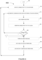
- FIG. 6 is a flowchart illustrating an example process 600 used by an AP.
- the process starts in step 605 and proceeds to step 610 where the AP initiates connection to the network 150 such as the enterprise intranet, the internet or in general to the cloud.
- the AP monitors the message exchange with the various servers that control and facilitate the association of the AP with the cloud 150.
- the process proceeds to step 620 where the message exchange and/or the internal status of the AP is stored in a log.
- the process proceeds to step 625 where the connectivity of the AP with the cloud 150 is monitored.
- AP may fail to connect to the cloud or otherwise, it may lose connectivity after initial connectivity has been achieved.
- the AP may, and often does, send keep-alive messages to the NMS 136 and monitor the reply acknowledgement messages from the NMS.
- step 630 the AP determines if the AP is still connected to the network. If the method detects that the AP is still connected to the network, the process loops back to 615 where the process continues to monitor the communication between the AP and the network including communication with other servers attached to the cloud 150.
- step 630 determines at step 630 that the AP cannot connect to the network or has lost connectivity to the network
- step 635 the ERM module of the isolated AP forms, generates, assembles or selects an error message(s).
- step 640 the error message is optionally displayed by the LED(s) informing observers in the vicinity of the isolated AP about the nature of the failure.
- step 645 the error message is conveyed to the transmitter for the location beacon such as transmitter e.g., module 246 of Figure 2 , and broadcast over the wireless channel, e.g., over a BLE radio frequency.
- the process then loops back to step 610 where the process retries to establish connectivity to the network.
- the process of retrying to connect to the network/cloud may be a single event, a few attempts before stopping the attempt, or repeated periodically optionally after rebooting, or the like.
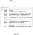
- Figure 7 is an illustrative example of error codes and corresponding LED sequences 700 shown in table form.
- Column 710 illustrates various error codes that facilitate an example way to convey information about specific issues that an isolated AP may encounter.
- Column 720 provides an example of a sequence of blinking that may visually convey an error code to an observer near the AP.
- the sequence of LED blinking to convey an error code 1 is a blink, short pause (denoted by the + sign) followed by a single blink, long pause, and then repeat this sequence.
- the LED follows the following sequence: a blink, short pause followed by 2 blinks, long pause, and then repeat this sequence.
- n In general, to convey error code n the LED follows the following sequence: a blink, short pause followed by a n blinks, long pause, and then repeat this sequence.
- Column 730 provides verbal explanations about the nature of the error and column 710 provides the serial number of each error code.
- Figure 8 is a flowchart illustrating an example process 800 used by a neighboring device, e.g., an AP, WT, etc., that receives the broadcast error message from an isolated AP which is not being able to connect to the network/cloud.
- a neighboring device e.g., an AP, WT, etc.
- the isolated device broadcasts a message which includes its device ID as well as a trouble code, such as the codes described in Figure 7 , column 710.
- the receiving device takes the ID of the isolated device and trouble code (which it has received over the broadcast BLE channel) and forms a message to be sent over a normal e.g., IP LAN/WAN connected to the network management server.
- the payload in this message includes the ID of the isolated AP and the trouble code received from that AP.
- step 805 The process starts step 805 and proceeds to step 810 where the method monitors broadcast beacon messages, e.g., BLE beacon messages.
- step 815 the received beacon message is analyzed and a determination made whether the received broadcast message is a normal beacon message such as beacon messages that are used to facilitate identifying the location of mobile terminals.
- the method at step 815 determines that the received beacon message is a normal broadcast beacon message, the method loops back to step 810 and continues to monitor the airways for additional broadcast beacon messages.
- some devices may utilize the normal beacon message for other applications such as to facilitate determining the location of the device. For example, if the system determines that the beacon message is a normal beacon message used for location determination, a mobile device forms a location application specific message which includes the ID of the beacon and the RSSI of the beacon message and forwards it to the location server such as the location server 134 of Figure 1 .
- the disclosed technology addresses the treatment of specific beacon messages such as broadcasted error message, treatment of normal, non-error messages can optionally be ignored.
- step 815 it is determined that the received broadcast beacon message is an error message from an isolated AP, the method proceeds to step 820.
- step 820 it is checked whether the device that received the error message is connected to the network/cloud. If it is determined that the device that received the error message is not connected to the network/cloud, the process continues to step 635 of Figure 6 where the device that received the error message may, and often does, also broadcast an error beacon message.
- step 820 it is determined that the device that received the error message is connected to the network/cloud, the process continues to step 825 where an appropriate message is formed.
- This message may, and often does, include the error code received from the isolated AP which was not able to connect to the cloud.
- the message may include also any additional information about the root cause of the issues experienced by the AP prior to its inability to connect to the cloud.
- step 830 the message from step 825 is transmitted via the cloud/network to the network monitoring server.
- the receiving device is one that has the IP address of the network management, the device may, and often does, send the message directly to the network management system.
- the receiving device is a mobile device that is tuned to receive the BLE beacon and forward the RSSI from different beacons to the location server, such as server 134 of figure 1 , the mobile device may, and often does, send the formatted error message to the IP address of the location server which would in turn recognize this message and forward it to the network management server 136.
- the process then loops back to step 810.
- Figure 9A is a flowchart illustrating an example process 900a used by an application server such as location server 134.
- the process starts in step 905 and proceeds to step 910 where the messages are received, such as messages received via internet receiver e.g., receiver 420 of figure 4 .
- the received messages are analyzed in step 915 for whether they are messages from a neighboring device reporting about an isolated AP which cannot connect to the network/cloud.
- step 915 If in step 915 it is determined that the received message is a normal application related message, e.g., a location related message from a mobile device reporting RSSI from a broadcasted beacon, and not a message from a neighboring device reporting about an isolated AP which does not have connectivity to the cloud, control loops back to step 910 and the system waits for a next received message.
- This normal application specific message such as RSSI message for location processing, is highlighted in step 917.
- step 915 it is determined that the received message is a message from a neighboring device such as e.g., mobile device reporting about an isolated AP which cannot connect to the network/cloud
- the process continues to step 920 where the method forwards the message with the ID of the isolated AP, the error code, and optionally any additional debugging information to the network monitoring server such as server 136 of Figure 1 .
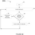
- FIGB is a flowchart illustrating an example process 900b used by a network management server 136.
- the process starts in step 950 and proceeds to step 960 where the messages are received, such as messages received via internet receiver e.g., receiver 332 of figure 3 .
- the received messages are analyzed in step 965 for whether they are messages from a neighboring device reporting about an isolated AP which cannot connect to the network/cloud.
- these messages may be sent directly by the neighboring device to the network monitoring device, or alternatively, these messages may be sent by the receiving device to an application server such as the location server, which in turn forwards the message error message from the isolated AP to the network monitoring server 136.
- step 965 If in step 965 it is determined that the received message is not a message from a neighboring device reporting about an isolated AP which does not have connectivity to the cloud, the method proceeds to step 967 where the network management system processes the messages in accordance with its normal operations (which are note detailed herein in the interests of brevity). The method then loops back to step 960 and the network monitoring system waits for a next received message.
- step 965 it is determined that the received message is a message from a neighboring device reporting about an isolated AP which cannot connect to the network/cloud
- the process continues to step 970 where the method invokes a corrective measure.
- the simplest corrective measure involves alerting an IT technician via a message on a screen such as module 308 of Figure 3 or sending an alert message via a text message, an e-mail, or an outbound call.
- the network management system invokes an automated corrective measure e.g., one or more of restarting a DHCP server, restarting AAA server, restarting a router, restarting a switch, reconfiguring a firewall, reconfiguring a server, etc.
- the specific remedial measure that the system should take in response to receiving a specific effort message can be, and often are, configured by an IT technician, or simply programmed into the system.
- Figure 10 is an illustration of an example table 1000 which provides examples of automated corrective measures associated with error codes.
- Column 1010 of Figure 10 which is the same as column 710 of figure 7 , illustrates various error codes that facilitate an example of a way to convey information about specific issues that an AP may encounter.
- These error codes originate at an isolated AP that cannot connect to the network/cloud, received by a neighboring device via a broadcast beacon message such as via Bluetooth ® or BLE (or comparable communication protocol), and conveyed by the neighboring device connected to the network/cloud via a Wi-Fi link or a cellular link.
- the network monitoring server which is a part of the network management system, receives and analyzes the message, uses column 1020 of table 1000 to identify an appropriate remedial action. Examples of such remedial messages are provided in column 1020.
- Various embodiments may be implemented using software, hardware and/or a combination of software and hardware.
- Various embodiments are directed to apparatus, e.g., mobile nodes, mobile wireless terminals, base stations, e.g., access points, communications system.
- Various embodiments are also directed to methods, e.g., method of controlling and/or operating a communications device, e.g., wireless terminals (UEs), base stations, control nodes, access points and/or communications systems.
- UEs wireless terminals
- Various embodiments are also directed to machine readable media, e.g., computer, readable medium, e.g., ROM, RAM, CDs, hard discs, carrier waves, transmission signals, etc., which include machine readable instructions for controlling a machine to implement one or more steps of a method.
- machine readable media e.g., computer, readable medium, e.g., ROM, RAM, CDs, hard discs, carrier waves, transmission signals, etc.
- devices and nodes described herein are implemented using one or more modules to perform the steps corresponding to one or more methods, for example, signal generation, transmitting, processing, and/or receiving steps.
- various features are implemented using modules.
- modules may be implemented using software, hardware or a combination of software and hardware.
- each module is implemented as an individual circuit with the device or system including a separate circuit for implementing the function corresponding to each described module.
- machine executable instructions such as software, included in a machine-readable medium such as a memory device, e.g., RAM, floppy disk, etc.
- various embodiments are directed to a machine-readable medium e.g., a non-transitory computer readable storage medium, including machine executable instructions for causing a machine, e.g., processor and associated hardware, to perform one or more of the steps of the above-described method(s).
- a machine readable medium e.g., a non-transitory computer readable storage medium
- transient transmission medium which convey between or within computer systems such machine executable instructions for causing a machine, e.g., processor and associated hardware, to perform one or more of the steps of the above-described method(s).
- Some embodiments are directed to a device including a processor configured to implement one, multiple or all of the steps of one or more methods of the presently taught approaches.
- the processor or processors e.g., CPUs, of one or more devices, e.g., communications devices such as wireless terminals (WT), user equipment (UEs), and/or access nodes, are configured to perform the steps of the methods described as being performed by the devices.
- the configuration of the processor may be achieved by using one or more modules, e.g., software modules, to control processor configuration and/or by including hardware in the processor, e.g., hardware modules, to perform the recited steps and/or control processor configuration.
- some but not all embodiments are directed to a communications device, e.g., user equipment, with a processor which includes a module corresponding to each of the steps of the various described methods performed by the device in which the processor is included.
- a communications device includes a module corresponding to each of the steps of the various described methods performed by the device in which the processor is included.
- the modules may be implemented purely in hardware, e.g., as circuits, or may be implemented using software and/or hardware or a combination of software and hardware.
- Some embodiments are directed to a computer program product comprising a computer-readable medium comprising code for causing a computer, or multiple computers, to implement various functions, steps, acts and/or operations, e.g. one or more steps described above.
- the computer program product can, and sometimes does, include different code for each step to be performed.
- the computer program product may, and sometimes does, include code for each individual step of a method, e.g., a method of operating a communications device, e.g., a wireless terminal or node.
- the code may be in the form of machine, e.g., computer, executable instructions stored on a computer-readable medium such as a RAM (Random Access Memory), ROM (Read Only Memory) or other type of storage device.
- some embodiments are directed to a processor configured to implement one or more of the various functions, steps, acts and/or operations of one or more methods described above. Accordingly, some embodiments are directed to a processor, e.g., CPU, graphical processing unit (GPU), digital signal processing (DSP) unit, etc., configured to implement some or all of the steps of the methods described herein.
- the processor may be for use in, e.g., a communications device or other device described in the present application.
- the methods and apparatus may be, and in various embodiments are, used with BLE, LTE, CDMA, orthogonal frequency division multiplexing (OFDM), and/or various other types of communications techniques which may be used to provide wireless communications links between access nodes and mobile nodes.
- the access nodes are implemented as base stations which establish communications links with user equipment devices, e.g., mobile nodes, using OFDM and/or CDMA.
- the mobile nodes are implemented as notebook computers, personal data assistants (PDAs), or other portable devices including receiver/transmitter circuits and logic and/or routines, for implementing the methods.
- Some embodiments may be used in conjunction with various devices and systems, for example, a User Equipment (LTE), a Mobile Device (MD), a wireless station (STA), a wireless terminal (WT), a Personal Computer (PC), a desktop computer, a mobile computer, a laptop computer, a notebook computer, a tablet computer, a server computer, a handheld computer, a handheld device, a Personal Digital Assistant (PDA) device, a handheld PDA device, an on-board device, an off-board device, a hybrid device, a vehicular device, a nonvehicular device, a mobile or portable device, a consumer device, a non-mobile or non-portable device, a wireless communication station, a wireless communication device, a wireless Access Point (AP), a wired or wireless router, a wired or wireless switch, a wired or wireless modem, a video device, an audio device, an audio-video (A/V) device, a wired or wireless network, a wireless area network, a Wireless Video Area Network
- Some embodiments may be used in conjunction with devices and/or networks operating in accordance with existing Wireless-Gigabit-Alliance (WGA) specifications (Wireless Gigabit Alliance, Inc. WiGig MAC and PHY Specification Version 1.1, April 2011, Final specification) and/or future versions and/or derivatives thereof, devices and/or networks operating in accordance with existing IEEE 802.11 standards (IEEE 802.11-2012, IEEE Standard for Information technology--Telecommunications and information exchange between systems Local and metropolitan area networks--Specific requirements Part 11: Wireless LAN Medium Access Control (MAC) and Physical Layer (PHY) Specifications, March 29, 2012; IEEE802.11ac-2013 ("IEEE P802.11ac-2013, IEEE Standard for Information Technology - Telecommunications and Information Exchange Between Systems - Local and Metropolitan Area Networks - Specific Requirements - Part 11: Wireless LAN Medium Access Control (MAC) and Physical Layer (PHY) Specifications - Amendment 4: Enhancements for Very High Throughput for Operation in Bands below 6GHz", December, 2013); IEEE 802.
- Some embodiments may be used in conjunction with one way and/or two-way radio communication systems, cellular radio-telephone communication systems, a mobile phone, a cellular telephone, a wireless telephone, a Personal Communication Systems (PCS) device, a PDA device which incorporates a wireless communication device, a mobile or portable Global Positioning System (GPS) device, a device which incorporates a GPS receiver or transceiver or chip, a device which incorporates an RFID element or chip, a Multiple Input Multiple Output (MIMO) transceiver or device, a Single Input Multiple Output (SIMO) transceiver or device, a Multiple Input Single Output (MISO) transceiver or device, a device having one or more internal antennas and/or external antennas, Digital Video Broadcast (DVB) devices or systems, multistandard radio devices or systems, a wired or wireless handheld device, e.g., a Smartphone, a Wireless Application Protocol (WAP) device, or the like.
- WAP Wireless Application Protocol
- Some embodiments may be used in conjunction with one or more types of wireless communication signals and/or systems, for example, Radio Frequency (RF), Infra-Red (IR), Frequency-Division Multiplexing (FDM), Orthogonal FDM (OFDM), Orthogonal Frequency-Division Multiple Access (OFDMA), FDM Time-Division Multiplexing (TDM), Time-Division Multiple Access (TDMA), Multi-User MIMO (MU-MIMO), Spatial Division Multiple Access (SDMA), Extended TDMA (E-TDMA), General Packet Radio Service (GPRS), extended GPRS, Code-Division Multiple Access (CDMA), Wideband CDMA (WCDMA), CDMA 2000, singlecarrier CDMA, multi-carrier CDMA, Multi-Carrier Modulation (MDM), Discrete Multi-Tone (DMT), Bluetooth , Global Positioning System (GPS), Wi-Fi, Wi-Max, ZigBeeTM, Ultra-Wideband (UWB), Global System for Mobile communication (
- Some demonstrative embodiments may be used in conjunction with a WLAN (Wireless Local Area Network), e.g., a Wi-Fi network.
- a WLAN Wireless Local Area Network
- Other embodiments may be used in conjunction with any other suitable wireless communication network, for example, a wireless area network, a "piconet", a WPAN, a WVAN, and the like.
- Some demonstrative embodiments may be used in conjunction with a wireless communication network communicating over a frequency band of 2.4Ghz, 5 GHz and/or 60 GHz.
- other embodiments may be implemented utilizing any other suitable wireless communication frequency band(s), for example, an Extremely High Frequency (EHF) band (the millimeter wave (mmWave) frequency band), e.g., a frequency band within the frequency band of between 20GhH and 300GHz, a WLAN frequency band, a WPAN frequency band, a frequency band according to the WGA specification, and the like.
- EHF Extremely High Frequency
- mmWave millimeter wave
- the terms “plurality” and “a plurality” as used herein may include, for example, “multiple” or “two or more”.
- the terms “plurality” or “a plurality” may be used throughout the specification to describe two or more components, devices, elements, units, parameters, circuits, or the like.
- a plurality of stations may include two or more stations.
- a Domain Master can also be used to refer to any device, system or module that manages and/or configures or communicates with any one or more aspects of the network or communications environment and/or transceiver(s) and/or stations and/or access point(s) described herein.
- the components of the system can be combined into one or more devices, or split between devices, such as a transceiver, an access point, a station, a Domain Master, a network operation or management device, a node or collocated on a particular node of a distributed network, such as a communications network.
- the components of the system can be arranged at any location within a distributed network without affecting the operation thereof.
- the various components can be located in a Domain Master, a node, a domain management device, such as a MIB, a network operation or management device, a transceiver(s), a station, an access point(s), or some combination thereof.
- one or more of the functional portions of the system could be distributed between a transceiver and an associated computing device/system.
- the various links including any communications channel(s)/elements/lines connecting the elements, can be wired or wireless links or any combination thereof, or any other known or later developed element(s) capable of supplying and/or communicating data to and from the connected elements.
- module as used herein can refer to any known or later developed hardware, circuitry, software, firmware, or combination thereof, that is capable of performing the functionality associated with that element.
- determine, calculate, and compute and variations thereof, as used herein are used interchangeable and include any type of methodology, process, technique, mathematical operational or protocol.
- a method for mitigating, by a network monitoring server, the root cause of an AP not having a first communication channel with the cloud comprising:
- forming a status message comprises:
- any of the above aspects, wherein using a beacon signal over a second communication channel to broadcast the formed message comprises one or more of:
- first communication channel is a Wi-Fi or wireless communication channel.
- the second channel is a BLE broadcast communication channel.
- the third communication channel is one of: a wired internet backhaul connectivity, a wireless Wi-Fi connectivity, and a cellular connectivity.
- invoking a correction measures comprises one or more of: restarting a network attached device,
- the network attached server is one of:
- Additional example aspects are directed toward: A method to mitigate a root cause of an access point not having connectivity with a network comprising:
- first communication channel is a wired communication channel.
- the second channel is a Bluetooth broadcast communication channel.
- the third communication channel is one of: a wired communication channel, an Ethernet communication channel, a wired internet backhaul communication channel, a Wi-Fi communication channel, and a cellular communication channel.
- the network attached device is one of: a DHCP server, an AAA server, a DNS server, a router, a proxy server, and a firewall.
- communication from the isolated access point includes communication over one or more wireless transceivers to a mobile device.
- a system to mitigate a root cause of an access point not having connectivity with a network comprising:
- first communication channel is a wired communication channel.
- the second channel is a Bluetooth broadcast communication channel.
- the third communication channel is one of: a wired communication channel, an Ethernet communication channel, a wired internet backhaul communication channel, a Wi-Fi communication channel, and a cellular communication channel.
- network monitoring server further:
- the network attached device is one of: a DHCP server, an AAA server, a DNS server, a router, a switch, a proxy server, and a firewall.
- communication from the isolated access point includes communication over one or more wireless transceivers to a mobile device.
- a system to mitigate a root cause of an access point not having connectivity with a network comprising:
- first communication channel is a wired communication channel.
- the second channel is a Bluetooth broadcast communication channel.
- the third communication channel is one of: a wired communication channel, an Ethernet communication channel, a wired internet backhaul communication channel, a Wi-Fi communication channel, and a cellular communication channel.
- the network attached device is one of: a DHCP server, an AAA server, a DNS server, a router, a switch, a proxy server, and a firewall.
- communication from the isolated access point includes communication over one or more wireless transceivers to a mobile device.
- a computer readable information medium having thereon instructions that when executed perform any one or more of the above aspects.
- SoC system on a chip
- One or more means for performing any one or more of the above aspects are provided.
- the above-described system can be implemented on a wireless telecommunications device(s)/system, such an IEEE 802.11 transceiver, or the like.
- wireless protocols that can be used with this technology include IEEE 802.11a, IEEE 802.11b, IEEE 802.11g, IEEE 802.11n, IEEE 802.11ac, IEEE 802.11ad, IEEE 802.11af, IEEE 802.11ah, IEEE 802.11ai, IEEE 802.11aj, IEEE 802.11aq, IEEE 802.11ax, Wi-Fi, LTE, 4G, Bluetooth ® , WirelessHD, WiGig, WiGi, 3GPP, Wireless LAN, WiMAX, DensiFi SIG, Unifi SIG, 3GPP LAA (licensed-assisted access), and the like.
- the systems, methods and protocols can be implemented to improve one or more of a special purpose computer, a programmed microprocessor or microcontroller and peripheral integrated circuit element(s), an ASIC or other integrated circuit, a digital signal processor, a hard-wired electronic or logic circuit such as discrete element circuit, a programmable logic device such as PLD, PLA, FPGA, PAL, a modem, a transmitter/receiver, any comparable means, or the like.
- any device capable of implementing a state machine that is in turn capable of implementing the methodology illustrated herein can benefit from the various communication methods, protocols and techniques according to the disclosure provided herein.
- Examples of the processors as described herein may include, but are not limited to, at least one of Qualcomm ® Qualcomm ® Qualcomm ® Qualcomm ® Qualcomm ® Qualcomm ® Qualcomm ® 610 and 615 with 4G LTE Integration and 64-bit computing, Apple ® A7 processor with 64-bit architecture, Apple ® M7 motion coprocessors, Samsung ® Exynos ® series, the Intel ® Core TM family of processors, the Intel ® Xeon ® family of processors, the Intel ® Atom TM family of processors, the Intel Itanium ® family of processors, Intel ® Core ® i5-4670K and i7-4770K 22nm Haswell, Intel ® Core ® i5-3570K 22nm Ivy Bridge, the AMD ® FX TM family of processors, AMD ® FX-4300, FX-6300, and FX-8350 32nm Vishera, AMD ® Kaveri processors, Texas Instruments ® Jacinto C6000 TM automotive infota
- the disclosed methods may be readily implemented in software using object or object-oriented software development environments that provide portable source code that can be used on a variety of computer or workstation platforms.
- the disclosed system may be implemented partially or fully in hardware using standard logic circuits or VLSI design. Whether software or hardware is used to implement the systems in accordance with the embodiments is dependent on the speed and/or efficiency requirements of the system, the particular function, and the particular software or hardware systems or microprocessor or microcomputer systems being utilized.
- the communication systems, methods and protocols illustrated herein can be readily implemented in hardware and/or software using any known or later developed systems or structures, devices and/or software by those of ordinary skill in the applicable art from the functional description provided herein and with a general basic knowledge of the computer and telecommunications arts.
- the disclosed methods may be readily implemented in software and/or firmware that can be stored on a storage medium to improve the performance of: a programmed general-purpose computer with the cooperation of a controller and memory, a special purpose computer, a microprocessor, or the like.
- the systems and methods can be implemented as program embedded on personal computer such as an applet, JAVA.RTM. or CGI script, as a resource residing on a server or computer workstation, as a routine embedded in a dedicated communication system or system component, or the like.
- the system can also be implemented by physically incorporating the system and/or method into a software and/or hardware system, such as the hardware and software systems of a communications transceiver.
- Methods and apparatus for automatically obtaining status from an isolated AP that cannot connect to the cloud are then used to automatically mitigate the issue and accelerate connecting the isolated AP back to the cloud.
- the methods are well suited for use in a system with a variety of access points, e.g., wireless and/or wired access points, which can be used to obtain access to the Internet or another network such as "the cloud”.
- Network management system has been configured to monitor the network and use preconfigured data to determine a remedial action to be automatically taken when an AP loses connectivity with the cloud.
- a method to mitigate a root cause of an access point not having connectivity with a network comprising: detecting, by an isolated access point, that connectivity to the network over a first communication channel has failed; automatically generating or acquiring, by a processor and memory, a status message related to the connectivity failure; automatically broadcasting, using a beacon signal, and over a second communication channel different than the first communication channel, the status message; receiving, by a neighboring device, the status message from the isolated access point over the second communication channel; forwarding via transmitting, by the neighboring device, the status message to a network monitoring server over a third communication channel, the third communication channel being different than the first and second communications channels; receiving, at the network monitoring server, the status message; and automatically invoking a mitigating action for the isolated access point.
- Clause 2 The method of clause 1, further comprising: logging messages exchanged between the isolated access point and other servers; analyzing the message exchange; and determining abnormal messages or an absence of reply messages from the other servers.
- Clause 3 The method of clause 1 or 2, further comprising: determining by the isolated access point an abnormal message flow; mapping the abnormal message flow to an error code; forming an error message comprising one or more of: the error code, messages from the isolated access point to one or more other devices, messages received by the isolated access point from one or more other devices, and/or timeout events detected by the isolated access point.
- the third communication channel is one of: a wired communication channel, an Ethernet communication channel, a wired internet backhaul communication channel, a Wi-Fi communication channel, and a cellular communication channel.
- Clause 8 The method of any preceding clause, further comprising one or more of: restarting a network attached device; configuring a network attached device; displaying an error message; and/or providing error message information to a technician.
- the network attached device is one of: a DHCP server, an AAA server, a DNS server, a router, a switch, a proxy server, and a firewall.
- Clause 10 The method of any preceding clause, wherein communication from the isolated access point includes communication over one or more wireless transceivers to one or more of an access point and a mobile device.
- a system to mitigate a root cause of an access point not having connectivity with a network comprising: an isolated access point including an error reporting module, processor and memory that detect that connectivity to the network over a first communication channel has failed; the processor and memory automatically generating or acquiring a status message related to the connectivity failure; a transceiver that automatically broadcasts, with a beacon signal, and over a second communication channel different than the first communication channel, the status message; a second transceiver in a neighboring device that receives the status message from the isolated access point over the second communication channel; the second transceiver forwarding via transmission the status message to a network monitoring server over a third communication channel, the third communication channel being different than the first and second communications channels; the network monitoring server receiving the status message and automatically invoking a mitigating action for the isolated access point.
- Clause 12 The system of clause 11, further comprising: storage that logs messages exchanged between the isolated access point and other servers; the processor further analyses the message exchange and determines abnormal messages or an absence of reply messages from the other servers.
- Clause 13 The system of clause 11 or 12, further comprising: instructions that determine in the isolated access point an abnormal message flow; instructions that maps the abnormal message flow to an error code; instructions that form an error message comprising one or more of: the error code, messages from the isolated access point to one or more other devices, messages received by the isolated access point from one or more other devices, and/or timeout events detected by the isolated access point.
- Clause 15 The system of any of clauses 11 to 14, wherein first communication channel is a wired communication channel.
- Clause 16 The system of any of clauses 11 to 15, wherein the second channel is a Bluetooth broadcast communication channel.
- Clause 17 The system of any of clauses 11 to 16, wherein the third communication channel is one of: a wired communication channel, an Ethernet communication channel, a wired internet backhaul communication channel, a Wi-Fi communication channel, and a cellular communication channel.
- Clause 18 The system of any of clauses 11 to 17, wherein the network monitoring server further: automatically restarts a network attached device; automatically configures a network attached device; automatically displays an error message; and/or automatically provides error message information to a technician.
- the network attached device is one of: a DHCP server, an AAA server, a DNS server, a router, a switch, a proxy server, and a firewall.
- Clause 20 The system of any of clauses 11 to 19, wherein communication from the isolated access point includes communication over one or more wireless transceivers to one or more of an access point and a mobile device.
Landscapes
- Engineering & Computer Science (AREA)
- Computer Networks & Wireless Communication (AREA)
- Signal Processing (AREA)
- Computer Security & Cryptography (AREA)
- Multimedia (AREA)
- Environmental & Geological Engineering (AREA)
- Mobile Radio Communication Systems (AREA)
- Information Transfer Between Computers (AREA)
- Management, Administration, Business Operations System, And Electronic Commerce (AREA)
Applications Claiming Priority (2)
| Application Number | Priority Date | Filing Date | Title |
|---|---|---|---|
| US16/296,902 US10862742B2 (en) | 2019-03-08 | 2019-03-08 | Method for conveying AP error codes over BLE advertisements |
| EP20161634.9A EP3706370B1 (de) | 2019-03-08 | 2020-03-06 | Verfahren zur übertragung von ap-fehlercodes über ble-werbung |
Related Parent Applications (1)
| Application Number | Title | Priority Date | Filing Date |
|---|---|---|---|
| EP20161634.9A Division EP3706370B1 (de) | 2019-03-08 | 2020-03-06 | Verfahren zur übertragung von ap-fehlercodes über ble-werbung |
Publications (2)
| Publication Number | Publication Date |
|---|---|
| EP4297489A2 true EP4297489A2 (de) | 2023-12-27 |
| EP4297489A3 EP4297489A3 (de) | 2024-02-28 |
Family
ID=69780097
Family Applications (2)
| Application Number | Title | Priority Date | Filing Date |
|---|---|---|---|
| EP20161634.9A Active EP3706370B1 (de) | 2019-03-08 | 2020-03-06 | Verfahren zur übertragung von ap-fehlercodes über ble-werbung |
| EP23205320.7A Pending EP4297489A3 (de) | 2019-03-08 | 2020-03-06 | Verfahren zur übertragung von ap-fehlercodes über ble-werbung |
Family Applications Before (1)
| Application Number | Title | Priority Date | Filing Date |
|---|---|---|---|
| EP20161634.9A Active EP3706370B1 (de) | 2019-03-08 | 2020-03-06 | Verfahren zur übertragung von ap-fehlercodes über ble-werbung |
Country Status (6)
| Country | Link |
|---|---|
| US (3) | US10862742B2 (de) |
| EP (2) | EP3706370B1 (de) |
| JP (1) | JP2020145675A (de) |
| CN (2) | CN113727284B (de) |
| AU (1) | AU2020201459A1 (de) |
| CA (1) | CA3070840A1 (de) |
Families Citing this family (62)
| Publication number | Priority date | Publication date | Assignee | Title |
|---|---|---|---|---|
| US10985969B2 (en) | 2019-02-19 | 2021-04-20 | Juniper Networks, Inc. | Systems and methods for a virtual network assistant |
| US10862742B2 (en) | 2019-03-08 | 2020-12-08 | Juniper Networks, Inc. | Method for conveying AP error codes over BLE advertisements |
| US11129027B2 (en) | 2019-09-30 | 2021-09-21 | Juniper Networks, Inc. | Intelligent radio band reconfiguration of access points in a wireless network |
| US11570038B2 (en) | 2020-03-31 | 2023-01-31 | Juniper Networks, Inc. | Network system fault resolution via a machine learning model |
| US12004045B2 (en) | 2020-12-15 | 2024-06-04 | Juniper Networks, Inc. | Determining location based on dynamic path loss exponent (PLE) and intercept (Int) estimation |
| US11496373B2 (en) | 2021-01-26 | 2022-11-08 | Juniper Networks, Inc. | Enhanced conversation interface for network management |
| US11843957B2 (en) | 2021-04-06 | 2023-12-12 | Juniper Networks, Inc. | Detection of insufficient RF coverage areas in a wireless network |
| WO2022221036A1 (en) * | 2021-04-13 | 2022-10-20 | Arris Enterprises Llc | Notifying service provider of wi-fi gateway issues |
| US11743151B2 (en) | 2021-04-20 | 2023-08-29 | Juniper Networks, Inc. | Virtual network assistant having proactive analytics and correlation engine using unsupervised ML model |
| US12112177B2 (en) | 2021-06-16 | 2024-10-08 | Juniper Networks, Inc. | Policy driven zero touch provisioning of network devices |
| EP4364018A4 (de) | 2021-06-29 | 2025-04-23 | Juniper Networks, Inc. | Erkennung und abschwächung von netzwerkzugangsanomalien |
| US11973640B1 (en) | 2021-07-14 | 2024-04-30 | Juniper Networks, Inc. | Physical layer issue detection based on client-side behavior assessments |
| CN117203943A (zh) | 2021-08-06 | 2023-12-08 | 瞻博网络公司 | 基于端点和用户属性应用安全策略 |
| US11770290B2 (en) | 2021-08-13 | 2023-09-26 | Juniper Networks, Inc. | Network management actions based on access point classification |
| US12382368B2 (en) | 2021-08-13 | 2025-08-05 | Juniper Networks, Inc. | Wireless access point proximity zones |
| US12284626B2 (en) | 2021-08-24 | 2025-04-22 | Juniper Networks, Inc. | WiFi location enhancement |
| US11838172B2 (en) | 2021-08-31 | 2023-12-05 | Juniper Networks, Inc. | Identifying root cause of failures through detection of network scope failures |
| US12484012B2 (en) | 2021-09-13 | 2025-11-25 | Juniper Networks, Inc. | Determining locations of deployed access points |
| US11831519B2 (en) | 2021-09-13 | 2023-11-28 | Juniper Networks, Inc. | Configuration of EVPN topologies using a user interface |
| US11451449B1 (en) | 2021-09-13 | 2022-09-20 | Juniper Networks, Inc. | Configuration of EVPN topologies using a user interface |
| US12041510B2 (en) | 2021-10-22 | 2024-07-16 | Juniper Networks, Inc. | Location metrics for monitoring or control of wireless networks |
| US12082296B2 (en) | 2021-11-09 | 2024-09-03 | Juniper Networks, Inc. | Control of roaming in a wireless network using a variable mobility threshold |
| US12170935B2 (en) | 2021-11-30 | 2024-12-17 | Juniper Networks, Inc. | Determining orientation of deployed access points |
| US12040934B1 (en) | 2021-12-17 | 2024-07-16 | Juniper Networks, Inc. | Conversational assistant for obtaining network information |
| WO2023137374A1 (en) | 2022-01-14 | 2023-07-20 | Juniper Networks, Inc. | Conversational assistant dialog design |
| US11968075B2 (en) | 2022-01-14 | 2024-04-23 | Juniper Networks, Inc. | Application session-specific network topology generation for troubleshooting the application session |
| US11991046B2 (en) | 2022-01-17 | 2024-05-21 | Juniper Networks, Inc. | Determining an organizational level network topology |
| US20230275820A1 (en) * | 2022-02-28 | 2023-08-31 | Juniper Networks, Inc. | Successful connects metrics for monitoring and control of wireless or wired networks |
| US12003363B2 (en) * | 2022-03-04 | 2024-06-04 | Juniper Networks, Inc. | Automatically troubleshooting and remediating network issues via connected neighbors |
| US12232013B2 (en) | 2022-03-11 | 2025-02-18 | Juniper Networks, Inc. | Associating sets of data corresponding to a client device |
| US12166758B2 (en) | 2022-03-14 | 2024-12-10 | Juniper Networks, Inc. | Closed-loop network provisioning based on network access control fingerprinting |
| US12021722B2 (en) | 2022-03-22 | 2024-06-25 | Juniper Networks, Inc. | Detecting network events having adverse user impact |
| US12238565B2 (en) | 2022-03-24 | 2025-02-25 | Juniper Networks, Inc. | Cloud-based management of hardware compliance data for access point devices |
| US12302133B2 (en) | 2022-05-31 | 2025-05-13 | Juniper Networks, Inc. | Automatic upgrade planning |
| US12368712B2 (en) | 2022-06-14 | 2025-07-22 | Juniper Networks, Inc. | Organization identification of network access server devices into a multi-tenant cloud network access control service |
| US12192241B2 (en) | 2022-06-14 | 2025-01-07 | Juniper Networks, Inc. | Network access control intent-based policy configuration |
| US12289220B1 (en) | 2022-06-22 | 2025-04-29 | Juniper Networks, Inc. | Logical path down scope analysis |
| CN119497827A (zh) | 2022-06-30 | 2025-02-21 | 瞻博网络公司 | 对用于距离测量的无线信号的校正 |
| US12069498B2 (en) * | 2022-07-12 | 2024-08-20 | Dish Wireless L.L.C. | Group monitoring and management of network functions of public cloud-based 5G network |
| US12368717B1 (en) | 2022-09-16 | 2025-07-22 | Juniper Networks, Inc. | High availability multi-tenant cloud based network access control system |
| US20240235955A9 (en) | 2022-10-20 | 2024-07-11 | Juniper Networks, Inc. | Conversational assistant for troubleshooting a site |
| US12088453B2 (en) | 2022-12-01 | 2024-09-10 | Juniper Networks, Inc. | Network anomaly detection and mitigation |
| US20240223434A1 (en) | 2022-12-29 | 2024-07-04 | Juniper Networks, Inc. | Detecting wired client stuck |
| US12034588B1 (en) | 2022-12-30 | 2024-07-09 | Juniper Networks, Inc. | Diagnostics reporting for wide area network assurance system |
| US20240224075A1 (en) | 2022-12-30 | 2024-07-04 | Juniper Networks, Inc. | Automated wireless radio configuration |
| US12362987B1 (en) | 2022-12-30 | 2025-07-15 | Juniper Networks, Inc. | Access point health metrics |
| US20240224165A1 (en) | 2022-12-30 | 2024-07-04 | Juniper Networks, Inc. | Automatic grouping of deployed access points |
| US20240223489A1 (en) | 2022-12-30 | 2024-07-04 | Juniper Networks, Inc. | Synthetic testing |
| US20240334190A1 (en) | 2023-03-31 | 2024-10-03 | Juniper Networks, Inc. | Dynamic load balancing of radius requests from network access server device |
| US20240364581A1 (en) | 2023-04-28 | 2024-10-31 | Juniper Networks, Inc. | Feature identification of an issue of an application session |
| US12452712B2 (en) | 2023-05-15 | 2025-10-21 | Cisco Technology, Inc. | Resource-conserving telemetry for constrained devices |
| US20250007775A1 (en) * | 2023-06-29 | 2025-01-02 | Shasta Cloud, Inc. | Dynamic feedback information about a network error |
| WO2025038412A1 (en) | 2023-08-11 | 2025-02-20 | Juniper Networks, Inc. | Distributed link failure resilient low latency network access control with authentication offload |
| WO2025043167A1 (en) | 2023-08-24 | 2025-02-27 | Juniper Networks, Inc. | Autodetection and remediation of high processor usage at network devices |
| US20250112930A1 (en) | 2023-09-28 | 2025-04-03 | Juniper Networks, Inc. | Location based access control |
| EP4550740A1 (de) | 2023-10-31 | 2025-05-07 | Juniper Networks, Inc. | Erkennung von portfehlkonfiguration |
| US20250158894A1 (en) | 2023-11-13 | 2025-05-15 | Juniper Networks, Inc. | Wide area network issue prediction based on detection of service provider connection swapping |
| EP4580145A1 (de) | 2023-12-29 | 2025-07-02 | Juniper Networks, Inc. | Zugangspunkt, schalter und standortdefinierte redundanz |
| US20250267618A1 (en) | 2024-02-16 | 2025-08-21 | Juniper Networks, Inc. | Location determination of a device based on directional information of signals |
| US20250274787A1 (en) | 2024-02-28 | 2025-08-28 | Juniper Networks, Inc. | Network device testing with virtual client functions |
| US20250358170A1 (en) | 2024-05-14 | 2025-11-20 | Juniper Networks, Inc. | Access point loop detection |
| US20250358171A1 (en) | 2024-05-14 | 2025-11-20 | Juniper Networks, Inc. | Dynamic spectrum capture |
Citations (1)
| Publication number | Priority date | Publication date | Assignee | Title |
|---|---|---|---|---|
| US9743254B2 (en) | 2015-04-30 | 2017-08-22 | Mist Systems, Inc. | Methods and apparatus relating to the use of received signals to determine wireless terminal location and/or refine location determination models |
Family Cites Families (25)
| Publication number | Priority date | Publication date | Assignee | Title |
|---|---|---|---|---|
| US8576855B2 (en) * | 2006-05-17 | 2013-11-05 | Alcatel Lucent | System and method of interface association for interface operational status event monitoring |
| JP2008271126A (ja) * | 2007-04-19 | 2008-11-06 | Ntt Docomo Inc | 移動端末装置、移動端末装置の診断方法 |
| US20110032816A1 (en) * | 2007-11-28 | 2011-02-10 | Telefonaktiebolaget L M Ericsson (Publ) | Connection Failure Notification Method And Apparatus |
| CN101459926B (zh) * | 2007-12-14 | 2011-02-16 | 华为技术有限公司 | 保证业务数据传输的方法、网元设备及网络系统 |
| US9521055B2 (en) * | 2009-11-13 | 2016-12-13 | Verizon Patent And Licensing Inc. | Network connectivity management |
| EP2388947A1 (de) * | 2010-05-20 | 2011-11-23 | Thomson Licensing | Verfahren zur Bestimmung der Übertragungsqualität einer Kommunikationsverbindung sowie zugehörige Vorrichtung |
| ES2488396T3 (es) * | 2011-03-25 | 2014-08-27 | Airbus Ds Sas | Autenticación en un sistema de comunicaciones |
| US10116709B1 (en) * | 2011-08-22 | 2018-10-30 | Star2Star Communications, LLC | Systems and methods for optimizing application data delivery over third party networks |
| US9155027B1 (en) * | 2011-11-23 | 2015-10-06 | Marvell International Ltd. | 802.11 enhanced distributed channel access |
| KR20140116156A (ko) * | 2012-01-20 | 2014-10-01 | 후지쯔 가부시끼가이샤 | 링크 실패의 원인을 분석하는 방법, 및 네트워크 최적화 방법 및 장치 |
| EP2911440B1 (de) * | 2012-11-14 | 2017-01-11 | Huawei Technologies Co., Ltd. | Verfahren, vorrichtung und system zur aufrechterhaltung einer basisstation |
| US20150045022A1 (en) * | 2013-08-06 | 2015-02-12 | Gaby Prechner | Access points and methods for access point selection using an information data structure |
| WO2015030483A1 (en) * | 2013-08-27 | 2015-03-05 | Samsung Electronics Co., Ltd. | Method and system for random access procedure and radio link failure in inter-enb carrier aggregation |
| CN106105308B (zh) * | 2014-03-20 | 2019-12-20 | 富士通株式会社 | 无线通信装置及无线通信方法 |
| EP3253173B1 (de) * | 2015-01-26 | 2019-07-17 | Fujitsu Limited | Drahtloskommunikationssystem, basisstation und endgerät |
| JP2017532810A (ja) * | 2015-02-09 | 2017-11-02 | 株式会社東芝 | ワイヤレス通信方法および装置 |
| CN104935466B (zh) | 2015-06-17 | 2019-05-07 | 新华三技术有限公司 | 一种故障处理方法和装置 |
| US10270903B2 (en) * | 2015-08-21 | 2019-04-23 | Avaya Inc. | Failover announcements |
| EP3433809A4 (de) * | 2016-03-23 | 2019-10-02 | Fedex Corporate Services, Inc. | Systeme, vorrichtung und verfahren zur selbstanpassung einer rundfunkeinstellung eines knotens in einem drahtlosknotennetzwerk |
| US10390182B2 (en) * | 2016-05-31 | 2019-08-20 | Infinite Leap Holdings, Llc | Real-time location system (RTLS) having tags, beacons and bridges, that uses a combination of motion detection and RSSI measurements to determine room-location of the tags |
| CN113543031B (zh) | 2016-09-12 | 2024-04-26 | 工业科技有限公司 | 具有相关范围的信标广播的系统和方法 |
| US10257750B2 (en) | 2016-11-15 | 2019-04-09 | Mist Systems, Inc. | Methods and apparatus for capturing and/or using packets to facilitate fault detection |
| EP3422637A1 (de) | 2017-06-28 | 2019-01-02 | Thomson Licensing | Verfahren zur kommunikation einer fehlermeldung und zugehörige vorrichtung |
| US10862742B2 (en) | 2019-03-08 | 2020-12-08 | Juniper Networks, Inc. | Method for conveying AP error codes over BLE advertisements |
| US12003363B2 (en) | 2022-03-04 | 2024-06-04 | Juniper Networks, Inc. | Automatically troubleshooting and remediating network issues via connected neighbors |
-
2019
- 2019-03-08 US US16/296,902 patent/US10862742B2/en active Active
-
2020
- 2020-02-03 CA CA3070840A patent/CA3070840A1/en not_active Abandoned
- 2020-02-28 AU AU2020201459A patent/AU2020201459A1/en not_active Abandoned
- 2020-03-04 JP JP2020036568A patent/JP2020145675A/ja not_active Withdrawn
- 2020-03-06 CN CN202111003073.2A patent/CN113727284B/zh active Active
- 2020-03-06 CN CN202010153011.9A patent/CN111669713B/zh active Active
- 2020-03-06 EP EP20161634.9A patent/EP3706370B1/de active Active
- 2020-03-06 EP EP23205320.7A patent/EP4297489A3/de active Pending
- 2020-10-27 US US17/081,331 patent/US11575562B2/en active Active
-
2023
- 2023-02-01 US US18/163,180 patent/US12470456B2/en active Active
Patent Citations (1)
| Publication number | Priority date | Publication date | Assignee | Title |
|---|---|---|---|---|
| US9743254B2 (en) | 2015-04-30 | 2017-08-22 | Mist Systems, Inc. | Methods and apparatus relating to the use of received signals to determine wireless terminal location and/or refine location determination models |
Also Published As
| Publication number | Publication date |
|---|---|
| JP2020145675A (ja) | 2020-09-10 |
| CN111669713B (zh) | 2021-09-10 |
| CN113727284A (zh) | 2021-11-30 |
| EP3706370A1 (de) | 2020-09-09 |
| CA3070840A1 (en) | 2020-09-08 |
| US20230179472A1 (en) | 2023-06-08 |
| AU2020201459A1 (en) | 2020-09-24 |
| US20200287782A1 (en) | 2020-09-10 |
| US11575562B2 (en) | 2023-02-07 |
| CN111669713A (zh) | 2020-09-15 |
| CN113727284B (zh) | 2023-07-25 |
| EP4297489A3 (de) | 2024-02-28 |
| US12470456B2 (en) | 2025-11-11 |
| EP3706370B1 (de) | 2023-10-25 |
| US10862742B2 (en) | 2020-12-08 |
| US20210044477A1 (en) | 2021-02-11 |
Similar Documents
| Publication | Publication Date | Title |
|---|---|---|
| US12470456B2 (en) | Method for conveying AP error codes over BLE advertisements | |
| US12289194B2 (en) | Systems and methods for a virtual network assistant | |
| US12003363B2 (en) | Automatically troubleshooting and remediating network issues via connected neighbors | |
| EP4072188A1 (de) | Detektion von unzureichenden hf-abdeckungsbereichen in einem drahtlosen netzwerk | |
| EP4171106A1 (de) | Ortsmetriken zur überwachung oder steuerung von drahtlosen netzwerken | |
| US12284626B2 (en) | WiFi location enhancement | |
| EP4178261A1 (de) | Roaming-steuerung in einem drahtlosen netzwerk unter verwendung einer variablen mobilitätsschwelle | |
| US20250365647A1 (en) | Wireless access point proximity zones | |
| EP4236235A1 (de) | Erfolgreiche verbindung von metriken zur überwachung und steuerung von drahtlosen oder verdrahteten netzwerken | |
| EP4651454A1 (de) | Zugangspunktschleifenerkennung |
Legal Events
| Date | Code | Title | Description |
|---|---|---|---|
| PUAI | Public reference made under article 153(3) epc to a published international application that has entered the european phase |
Free format text: ORIGINAL CODE: 0009012 |
|
| STAA | Information on the status of an ep patent application or granted ep patent |
Free format text: STATUS: THE APPLICATION HAS BEEN PUBLISHED |
|
| AC | Divisional application: reference to earlier application |
Ref document number: 3706370 Country of ref document: EP Kind code of ref document: P |
|
| AK | Designated contracting states |
Kind code of ref document: A2 Designated state(s): AL AT BE BG CH CY CZ DE DK EE ES FI FR GB GR HR HU IE IS IT LI LT LU LV MC MK MT NL NO PL PT RO RS SE SI SK SM TR |
|
| REG | Reference to a national code |
Ref country code: DE Ref legal event code: R079 Free format text: PREVIOUS MAIN CLASS: H04W0048120000 Ipc: H04L0041063100 |
|
| PUAL | Search report despatched |
Free format text: ORIGINAL CODE: 0009013 |
|
| AK | Designated contracting states |
Kind code of ref document: A3 Designated state(s): AL AT BE BG CH CY CZ DE DK EE ES FI FR GB GR HR HU IE IS IT LI LT LU LV MC MK MT NL NO PL PT RO RS SE SI SK SM TR |
|
| RIC1 | Information provided on ipc code assigned before grant |
Ipc: H04L 41/0686 20220101ALN20240122BHEP Ipc: H04W 48/12 20090101ALI20240122BHEP Ipc: H04W 24/04 20090101ALI20240122BHEP Ipc: H04W 4/80 20180101ALI20240122BHEP Ipc: H04W 4/50 20180101ALI20240122BHEP Ipc: H04L 69/40 20220101ALI20240122BHEP Ipc: H04L 67/10 20220101ALI20240122BHEP Ipc: H04L 43/0811 20220101ALI20240122BHEP Ipc: H04L 41/0654 20220101ALI20240122BHEP Ipc: H04L 41/0631 20220101AFI20240122BHEP |
|
| STAA | Information on the status of an ep patent application or granted ep patent |
Free format text: STATUS: REQUEST FOR EXAMINATION WAS MADE |
|
| 17P | Request for examination filed |
Effective date: 20240816 |
|
| RBV | Designated contracting states (corrected) |
Designated state(s): AL AT BE BG CH CY CZ DE DK EE ES FI FR GB GR HR HU IE IS IT LI LT LU LV MC MK MT NL NO PL PT RO RS SE SI SK SM TR |