EP4297348A1 - Kollisionsvermeidung auf phy-ebene mit qos mit niedrigerer latenzzeit - Google Patents
Kollisionsvermeidung auf phy-ebene mit qos mit niedrigerer latenzzeit Download PDFInfo
- Publication number
- EP4297348A1 EP4297348A1 EP22180845.4A EP22180845A EP4297348A1 EP 4297348 A1 EP4297348 A1 EP 4297348A1 EP 22180845 A EP22180845 A EP 22180845A EP 4297348 A1 EP4297348 A1 EP 4297348A1
- Authority
- EP
- European Patent Office
- Prior art keywords
- shared media
- node
- priority
- frame
- communications
- Prior art date
- Legal status (The legal status is an assumption and is not a legal conclusion. Google has not performed a legal analysis and makes no representation as to the accuracy of the status listed.)
- Pending
Links
- 238000004891 communication Methods 0.000 claims abstract description 122
- 238000000034 method Methods 0.000 claims abstract description 53
- 230000005540 biological transmission Effects 0.000 claims abstract description 49
- 230000008901 benefit Effects 0.000 description 13
- 238000013459 approach Methods 0.000 description 12
- 230000007246 mechanism Effects 0.000 description 12
- 101100172132 Mus musculus Eif3a gene Proteins 0.000 description 7
- 230000006872 improvement Effects 0.000 description 7
- 230000006399 behavior Effects 0.000 description 5
- 239000000872 buffer Substances 0.000 description 5
- 230000006870 function Effects 0.000 description 5
- 230000003278 mimic effect Effects 0.000 description 4
- 238000011867 re-evaluation Methods 0.000 description 4
- 230000009467 reduction Effects 0.000 description 4
- 230000001419 dependent effect Effects 0.000 description 3
- 241001522296 Erithacus rubecula Species 0.000 description 2
- 238000001514 detection method Methods 0.000 description 2
- 238000005516 engineering process Methods 0.000 description 2
- 230000002093 peripheral effect Effects 0.000 description 2
- 230000001174 ascending effect Effects 0.000 description 1
- 230000009286 beneficial effect Effects 0.000 description 1
- 230000008859 change Effects 0.000 description 1
- 230000004069 differentiation Effects 0.000 description 1
- RXOIEVSUURELPG-UHFFFAOYSA-N fenozolone Chemical compound O1C(NCC)=NC(=O)C1C1=CC=CC=C1 RXOIEVSUURELPG-UHFFFAOYSA-N 0.000 description 1
- 235000003642 hunger Nutrition 0.000 description 1
- 230000000977 initiatory effect Effects 0.000 description 1
- 230000006855 networking Effects 0.000 description 1
- 238000000819 phase cycle Methods 0.000 description 1
- 230000008569 process Effects 0.000 description 1
- 238000012545 processing Methods 0.000 description 1
- 230000037351 starvation Effects 0.000 description 1
Images


Classifications
-
- H—ELECTRICITY
- H04—ELECTRIC COMMUNICATION TECHNIQUE
- H04L—TRANSMISSION OF DIGITAL INFORMATION, e.g. TELEGRAPHIC COMMUNICATION
- H04L12/00—Data switching networks
- H04L12/28—Data switching networks characterised by path configuration, e.g. LAN [Local Area Networks] or WAN [Wide Area Networks]
- H04L12/40—Bus networks
- H04L12/407—Bus networks with decentralised control
- H04L12/413—Bus networks with decentralised control with random access, e.g. carrier-sense multiple-access with collision detection [CSMA-CD]
-
- H—ELECTRICITY
- H04—ELECTRIC COMMUNICATION TECHNIQUE
- H04L—TRANSMISSION OF DIGITAL INFORMATION, e.g. TELEGRAPHIC COMMUNICATION
- H04L12/00—Data switching networks
- H04L12/28—Data switching networks characterised by path configuration, e.g. LAN [Local Area Networks] or WAN [Wide Area Networks]
- H04L12/40—Bus networks
- H04L12/40143—Bus networks involving priority mechanisms
- H04L12/4015—Bus networks involving priority mechanisms by scheduling the transmission of messages at the communication node
-
- H—ELECTRICITY
- H04—ELECTRIC COMMUNICATION TECHNIQUE
- H04L—TRANSMISSION OF DIGITAL INFORMATION, e.g. TELEGRAPHIC COMMUNICATION
- H04L12/00—Data switching networks
- H04L12/28—Data switching networks characterised by path configuration, e.g. LAN [Local Area Networks] or WAN [Wide Area Networks]
- H04L12/40—Bus networks
- H04L2012/40267—Bus for use in transportation systems
- H04L2012/40273—Bus for use in transportation systems the transportation system being a vehicle
Definitions
- the present disclosure relates to physical layer (PHY) devices.
- PHY physical layer
- the present disclosure relates to a method of operating a plurality of communications nodes each comprising a physical layer (PHY) device and coupled to a shared media, a communications node comprising a physical layer (PHY) device and coupled to a shared media, and a communications network comprising a shared media, herein the shared media may be a twisted-pair wire and a plurality of communications nodes coupled to the shared media.
- the present disclosure relates in particular to a method which compared to previous PLCA techniques lowers the worst-case latency for higher priority frames.
- Modern automobiles include various electronic control units (ECUs) that implement, for example, engine control, power train control, airbag systems, antilock brake systems, cruise control, electric power steering, audio systems, window control systems, door control systems, mirror adjustment systems, and battery and recharging systems for hybrid/electric cars.
- ECUs electronice control units
- the ECUs communicate with each other in an automobile via in-vehicle network (IVN) technologies such as Ethernet.
- IVN in-vehicle network
- Ethernet is a well-known technology and the Institute of Electrical and Electronic Engineers (IEEE) 802.3 Working Group is a collection of standards that define physical layer and data link layer media access control (MAC) for wired Ethernet.
- IEEE 802.3cg An emerging IEEE standard that may be particularly applicable to in-vehicle networks is IEEE 802.3cg, which is a protocol for 10 Mb/s single twisted-pair Ethernet that enables multiple nodes to connect to the same twisted-pair wire, also referred to as a "shared media.”
- the IEEE 802.3cg physical layer (PHY) utilizes CSMA/CD (Carrier Sense Multiple Access, Collision Detection) for media access control.
- CSMA/CD Carrier Sense Multiple Access, Collision Detection
- the 10 Mb/sec single-pair PHY project in IEEE defined a multi-drop mode of operation where multiple end-nodes or bridges are connected to a single twisted-pair wire network segment. In Ethernet terms, this network would be called a half-duplex network segment.
- the project did not define a new Ethernet MAC so the IEEE 802.3 standard Clause 4 MAC is used in half-duplex mode (CSMA/CD). This however causes a problem with the target application of Automotive since the CSMA/CD MAC is not deterministic.
- PHY Level Collision Avoidance PLCA
- PLCA is a protocol that can be applied in conjunction with IEEE 802.3cg to provide deterministic performance in in-vehicle networks.
- IEEE 802.3cg IEEE 802.3cg network
- applications such as in-vehicle networks may present additional challenges.
- the original proposed PLCA is fair in terms of equal framerate. Enhancements have been made to change this to equal data-rate fairness.
- the present disclosure provides an enhancement to PLCA which more closely mimics the well understood behaviour of a QoS Ethernet switch resulting in a lower latency for higher priority frames.
- a method of operating a plurality of communications nodes coupled to a shared media may comprise the following steps.
- Performing a first advertising phase comprising: identifying, at each of the plurality of communications nodes, a priority level of a next frame for transmission to the shared media by that communications node; transmitting, by each of the plurality of PHY devices, an indication of the priority level of the next frame of that communications node for transmission onto the shared media; receiving, at a Coordinator and/or each of the plurality communications nodes, the indications of priority levels of the next frames to be transmitted to the shared media from the plurality of communications nodes coupled to the shared media.
- the method may further comprise determining one next frame of the plurality of next frames to be a next transmitted frame to the shared media based on the received indications of priority levels of the plurality of next frames.
- Performing the first data phase may comprise transmitting the determined one next frame to the shared media.
- a second said advertising phase may be performed directly after the first data phase.
- the second advertising phase may take place after each transmitted frame on the media.
- the second advertising phase may be the same as the first advertising phase.
- the communication nodes each comprise a physical layer (PHY) device.
- the method according to the above steps lowers the worst-case scenario for higher priority frames compared to previous methods by performing a second advertising phase directly after the first data phase.
- Minimal bandwidth overhead is added by increasing advertising opportunities for the communications nodes to indicate that they have higher priority frames to transmit with the benefit of being able to transmit these higher priority frames more quickly compared to fewer advertising opportunities that occur only per full cycle of all transmit opportunities of each of the plurality of communications nodes.
- applications can choose for lower latency at the cost of slightly lower available bandwidth when QoS is needed on the shared media.
- the method may further comprise determining state information, wherein state information indicates which of the plurality of communications nodes transmitted a previous frame to the shared media in a previous data phase. Determining state information further mimics the behaviour of an Ethernet switch.
- the state information can be determined by the Coordinator.
- One of the plurality of communications nodes may be responsible for determining the state information and sharing information, such as a winning node of the plurality of nodes, with the other communications nodes.
- each communications node may determine the state information. For example, at each of the plurality of communications nodes.
- the method may further comprise indicating the priority level of the next frame by transmitting the indication in a media access priority beacon.
- determining which frame of the received next frames to be the next transmitted frame comprises determining that a priority level of one of the received next frames is higher than the priority levels of the other received next frames.
- determining which next frame to transmit may comprise determining which communications node transmitted the previous frame at that priority level; and determining which communications node is a next communications node in a predetermined sequence.
- the predetermined sequence may relate to Node number, for example in an ascending order (or a round robin approach).
- the method may further comprise a coordinator data beacon for synchronizing the plurality of communications nodes for the data phase.
- the method may further comprise transmit opportunities for a communications node that was not chosen to transmit the next frame to the shared media.
- the method may further comprise timeouts for idle nodes.
- the method may further comprise learning the priority level of the frames through an MII interface, a serial peripheral interface (SPI) or through information in a header of the second frame.
- MII magnetic resonance imaging
- SPI serial peripheral interface
- the method may further comprise indicating the priority level of the next frame by transmitting an indication of priority in a media access priority beacon.
- a communications node coupled to a shared media.
- the communications node may comprise a media access priority manager which may be configured to perform the following steps.
- the media access priority manager may: identify a priority level of a next frame for transmission to the shared media by the communications node; transmit an indication of the priority level of the next frame for transmission onto the shared media; receive either information concerning whether the communications node is a winning node or receiving indications of priority levels of other next frames for transmission onto the shared media from other Communications nodes coupled to the shared media.
- the media access priority manager may determine whether the next frame of the communications node is a one next frame to be transmitted to the shared media based on the received winning node information or the received indications of priority levels of the plurality of next frames from the other communications nodes coupled to the shared media. If the next frame is the one next frame, the media access priority manager may be configured to, in a first data phase, transmit the one next frame to the shared media. The media access priority manager may be configured to perform a second advertising phase directly after the first data phase.
- each communication node may comprise a physical layer (PHY) device.
- the media access priority manager may be configured to determine state information, wherein state information indicates which of the plurality of communications nodes transmitted a previous frame (e.g. at each priority level) to the shared media in a previous data phase.
- the state information may be determined by a Coordinator.
- Winning node information may be shared with the communications node by the Coordinator.
- the communications node may determine the state information.
- the media access manager can be configured to initiate transmission of the one next frame if the priority level of the one next frame is higher than the priority levels of the other next frames to be transmitted from the other communications nodes.
- next frame and one or more other next frames have the highest priority level, transmitting the next frame if the communications node is next in a predetermined sequence.
- a communications network Preferably wherein the communications network comprises: a shared media, wherein the shared media is a twisted-pair wire; and a plurality of communications nodes coupled to the shared media.
- Each communications node may comprise a media access priority manager configured to perform the following steps.
- the media access priority manager may be configured to identify a priority level of a next frame for transmission to the shared media by the communications node; transmit an indication of the priority level of the next frame for transmission onto the shared media; and receive either information concerning whether the communications node is a winning node or receiving indications of priority levels of other next frames for transmission onto the shared media from other communications nodes coupled to the shared media.
- the media access priority manager may be configured to determine whether the next frame of the communications node is a one next frame to be transmitted to the shared media based on the received winning node information or the received indications of priority levels of the plurality of next frames from the other communications nodes coupled to the shared media. If the next frame is the one next frame, the media access priority manager may, in a first data phase, transmit the one next frame to the shared media. The media access priority manager may further be configured to perform a second advertising phase after the first data phase.
- the media access manager may be configured to determine the one next frame by selecting the next frame with a highest priority level; or if two or more next frames have the highest priority level, select the one next frame from the communications node which is next in a predetermined sequence.
- the enhancements presented by the present disclosure compared to previous PLCA techniques lowers the worst-case latency for higher priority frames by adding minimal additional bandwidth overhead and local state information, to mimic the behaviour of Ethernet switches more closely.
- the enhancements may be described as Lower Latency QoS. Applications can choose lower latency over slightly lower bandwidth when QoS is needed on the PLCA reconciliation sublayer.
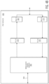
- FIG. 1 depicts a communications network 100 that includes multiple communications nodes 104 - 1 , 104 - 2 , ... , 104 -N (where N is an integer greater than one) that communicate through a shared media 102 , such as twisted-pair wires.
- each communications node includes a corresponding physical layer (PHY) device 106 - 1 , 106 - 2 ,..., or 106 -N (also referred to as a transceiver) and a corresponding media access control (MAC) unit 108 - 1 , 108 - 2 , ..., or 108 -N, the communications network configured to perform media access arbitration to orchestrate access to the shared media.
- PHY physical layer
- MAC media access control
- the MAC unit supports collision detection (CSMA/CD) and the PLCA (with and without QoS) is in the reconciliation sublayer, which is typically part of the PHY device.
- the communication nodes may be end nodes that include, for example, various electronic control units (ECUs) for engine control, power train control, airbags, antilock brakes, cruise control, electric power steering, audio systems, windows, doors, mirror adjustment, battery and recharging systems for hybrid/electric cars, and many more.
- the communications nodes may also be a node such as an Ethernet bridge. Although the illustrated communications nodes are shown with certain components and described with certain functionality herein, other embodiments of the communications nodes may include fewer or more components to implement the same, less, or more functionality.
- the communications network 100 is an Ethernet network that utilizes CSMA/CD for media access control and that is compatible with the emerging IEEE 802.3cg protocol, which currently specifies the physical layer for 10 Mb/s over a single twisted-pair cable.
- the PHY devices 106 - 1 , 106 - 2 ,..., 106 -N are configured to manage physical layer communications functions according to the IEEE 802.3cg specification. For example, the PHY devices transmit analog signals onto the shared media and receive analog signals from the shared media. The PHY devices may also protect other components in the node from extreme electrical conditions, e.g., electrical surges, which may occur on the shared media.
- the MAC units 108 - 1, 108 - 2 ,..., 108 -N are configured to perform media access control for the corresponding communications nodes 104 - 1 , 104 - 2 ,..., 104 -N.
- the MAC units may be implemented within a processor, such as a microcontroller, a host processor, a host, a digital signal processor (DSP), or a central processing unit (CPU).
- DSP digital signal processor
- CPU central processing unit
- at least one of the MAC units is included within the PHY layer module of an IEEE 802.3cg compatible Ethernet communications device.
- the illustrated MAC units are shown in FIG. 1 as included in the corresponding communications nodes, in some embodiments, the MAC units may be separated from the corresponding communications nodes.
- FIG. 2 illustrates an Ethernet communication network that includes two nodes, node A 204 - 1 and node B 204 - 2 , in an Ethernet based in-vehicle network that is, for example, compatible with IEEE 802.3cg.
- FIG. 2 also depicts the layers of the OSI reference model 240 as well as an expanded view of the physical layer and the data link layer. As shown in FIG.
- the OSI reference model includes the physical layer (also referred to as layer 1 or L1), the data link layer (also referred to as layer 2 or L2), the network layer (also referred to as layer 3 or L3), the transport layer (also referred to as layer 4 or L4), the session layer (also referred to as layer 5 or L5), the presentation layer (also referred to as layer 6 or L6), and the application layer (also referred to as layer 7 or L7).
- the physical layer also referred to as layer 1 or L1
- the data link layer also referred to as layer 2 or L2
- the network layer also referred to as layer 3 or L3
- the transport layer also referred to as layer 4 or L4
- the session layer also referred to as layer 5 or L5
- the presentation layer also referred to as layer 6 or L6
- the application layer also referred to as layer 7 or L7.
- Elements in the expanded view of the physical layer include media-dependent sublayers of the transmission medium 206 , a media-dependent interface (MDI) 242 , an auto-negotiation layer (AN2) 244 , a physical medium attachment (PMA) 246 , and the physical coding sublayer (PCS) 248 , and media-independent sublayers of a media-independent interface (Mil) 250 , and a reconciliation sublayer 252.
- the reconciliation sublayer 252 may comprise 10BASE-T1S PLCA.
- the 10BASE-T1S specification was developed as part of the IEEE 802.3cg standard, which was published in February 2020.
- 10BASE-T1S provides the missing link in the automotive Ethernet ecosystem, enabling true Ethernet-to-the-edge connectivity and addressing the needs of zonal architectures.
- the auto-negotiation may not be used.
- the AN2 layer may be replaced with a physical medium dependent (PMD) layer in such cases.
- PMD physical medium dependent
- the present disclosure may be used in 10BASE-T1S in multidrop mode.
- a PMD transceiver may be specified.
- elements of the PCS, PMA, and AN2 are included in a physical layer chip, often referred to as a "PHY chip" and or simply as a "PHY” as indicated in FIG. 2 .
- the PHY chip may also include the reconciliation layer.
- Elements in the expanded view of the data link layer include the media access control (MAC) layer 254 , the MAC control layer (optional) 256 , and the logical link control (LLC) 258 , or other MAC client layer.
- MAC media access control
- LLC logical link control
- Higher layers 260 may be implemented above the data link layer.
- FIG. 3 depicts an expanded view of a communications network 300 that includes three communications nodes 304 - 1 , 304 - 2 , and 304 - 3 that communicate over a shared media 302 according to the IEEE 802.3cg standard.
- each communications node includes a PHY device 306, a receive component of a MAC unit (referred to as an RX MAC 312), a receive FIFO 314, an end node function 316, transmit Quality of Service (QoS) queues 318, a frame selector 320, and a transmit component of a MAC unit (referred to as a TX MAC 322).
- the PHY devices 306 of the communications network implement PLCA on the IEEE 802.3cg 10BASE-T1S network in multidrop mode.
- PLCA is implemented at the physical layer and may be integrated with the reconciliation sublayer 252 ( FIG. 2 ).
- An operational principle of PLCA, when PLCA is optionally chosen to be used, is that each PHY device is assigned an identifier (ID) that is unique across the shared media and the PHY devices can only transmit data during specific ordered slots that correspond to their respective ID.
- ID identifier
- each communications node 304 - 1 , 304 - 2 , and 304 - 3 supports the QoS queues 318 in the respective transmit path.
- the four QoS queues are configured to queue frames that are to be transmitted from the corresponding communications node and each QoS queue corresponds to a different priority, e.g., high priority, medium priority, normal priority, and low priority, where the priorities are listed in descending priority order.
- the four QoS queues allow the differentiation of frame priority based upon the QoS queue in which a frame is placed.
- the frame selector 320 implements strict priority scheduling to select frames from the QoS queues.
- strict priority scheduling dictates that the highest priority queue is always emptied first and only when the highest priority queue is empty will a next lower priority queue be serviced. The next priority queue is serviced until that queue is emptied or until a higher priority queue receives a frame.
- strict priority schedulers are generally used because of their simplicity. To prevent starvation of the lower priority queues, the output of each queue on each node can be rate limited to ensure that the respective queues do not transmit more data than they should.
- each frame selector 320 can ensure a particular latency of frame delivery into its own TX MAC 322, a conventional PHY device that is compatible with IEEE 802.3cg (including PHY devices that implement Physical Layer Collision Avoidance, also referred to simply as "PLCA") cannot deliver such a differentiated service over the shared media. It may be desirable to be able to achieve a strict priority type of operation (other scheduling algorithms may be possible as well, but strict priority is particularly useful in in-vehicle networks) in an IEEE 802.3cg compliant communications network, including, for example, an IEEE 802.3cg compliant communications network that utilizes PLCA.
- IEEE 802.3cg compliant communications network including, for example, an IEEE 802.3cg compliant communications network that utilizes PLCA.
- fragmenting queued frames to prevent smaller higher priority frames from getting stuck behind larger (e.g., maximum sized) lower priority frames. Although this approach may work well to prevent smaller higher priority frames from getting stuck behind larger (e.g., maximum sized) lower priority frames, fragmenting queued frames may not provide the desired latency when, for example, on-the-wire priority is not considered. Additionally, fragmenting queued frames in each PHY device requires re-assembly buffers, e.g., one re-assembly buffer for each communications node on the shared media.
- the size of the buffers would have to be at least the size of two maximum size frames since a frame cannot be sent to a communications node until a previous transmission is complete and the transmissions could all complete at the same time.
- a second frame buffer may also be needed to receive the frames that may be received while transmitting the frames that were just received. Such an approach not only needs more memory, but it may also not solve the latency to the target communications node problem.
- Another approach according to the present disclosure comprises operating a PHY device 306 for media access control to a shared media and involves identifying a priority of a frame that is to be transmitted onto the shared media 302 from the PHY layer device 306 and transmitting an indication of the priority of the frame onto the shared media 302 from the PHY device 306 after every transmission of a frame onto the shared media 302.
- the PHY device 306 is optionally compatible with the IEEE 802.3 standard and utilizes CSMA/CD.
- the one or more other PHY devices 306 on the shared media 302 are able to know the priorities of pending frames of the respective PHY devices 306 connected to the shared media 302 and can transmit frames in a priority order (e.g., based on PHY level frame priority arbitration) that ensures that the highest priority frames waiting for access to the shared media 302 are transmitted onto the shared media 302 before lower priority frames.
- a priority order e.g., based on PHY level frame priority arbitration
- operating a PHY device 306 in an IEEE 802.3cg compliant communications network 300 also involves receiving priorities of frames to be transmitted onto the shared media 302 from other PHY devices 306 that are connected to the shared media 302 and determining, at the PHY level, whether or not to transmit its frame onto the shared media 302 based on the priority of its frame relative to the priorities of the frames that are waiting to be transmitted from the other PHY devices 306.
- the technique may further involve, at a particular PHY device 306, initiating transmission of its frame if the priority of its frame is higher than the priorities of all the other frames that are waiting to be transmitted from the other PHY devices 306 on the shared media 302.
- the indication of priority may be transmitted from a PHY device 306 in a media access priority beacon.
- the PHY device 306 may learn the priority of its frame from the MAC unit 322 through an MII interface. By sharing frame priorities at the PHY layer, an IEEE 802.3cg compliant communications network can implement a strict priority scheme at the physical layer, thus providing low latency for the highest priority frames.
- the mechanism can be further extended to improve coordination between all of the communications nodes 304 which are connected to the shared media 302.
- the coordination can be enhanced to mimic Ethernet switch mechanisms by re-evaluating the priority of the next frame that all of the End Nodes 316 want to transmit to the shared media 302 after each frame is transmitted over the network 300. Whilst this may increase the overhead due to additional advertising bandwidth required, overall latency for the highest priority frames can be reduced by not having to wait for a next "data" phase.
- State information concerns which End Node 316 transmitted the most recently transmitted frame and may, for example, further comprise information about the most recently transmitted frame at its priority level.
- the state information is handled in the PLCA. This results in "fairness" between the End Nodes. In some examples the state information may not be known by each of the End Nodes.
- the above-described technique is implemented at the physical layer (Layer 1) as specified in the OSI reference model (see OSI reference model layers 240 at FIG. 2 ).
- FIG. 4A depicts a media access priority manager 486 that is implemented at the physical layer (Layer 1) to achieve physical layer quality of service functionality.
- Layer 1 the physical layer
- the media access priority manager does not have to be implemented in Layer 1 and that other configurations are also possible.
- the media access priority manager implements functions to support the sharing of priority information at the physical layer and the priority arbitration, at the physical layer, amongst priorities received from other nodes on the communications network.
- the media access priority manager may also implement functions at the physical layer related to learning the priority of frames that are ready for transmission.
- the media access priority manager 486 operates in the reconciliation layer 452 between the PCS 448 of the physical layer and below the MAC layer 454 of the data link layer.
- FIG. 4B depicts components of a PHY device 406 that is configured to operate in compliance with IEEE 802.3cg.
- the PHY device includes a physical medium attachment receiver (PMA-RX) 474 , a physical coding sublayer receiver (PCS-RX) 476 , a physical coding sublayer transmitter (PCS-TX) 478 , a physical medium attachment transmitter (PMA-TX) 480 , and a media access priority manager 486 .
- the media access priority manager 486 is part of the PLCA.
- the PHY device is a standalone PHY chip that is connected to the shared media (e.g., twisted-pair wire) via the PMA-TX and PMA-RX and to another device in the communications node via an interface 488 such as an MII (e.g., reduced media-independent interface (RMII) referred to collectively as "xMII").
- MII reduced media-independent interface
- xMII reduced media-independent interface
- the media access priority manager is connected to another device in the communications node by another interface, such as a serial peripheral interface (SPI).
- SPI serial peripheral interface
- the media access priority manager 486 is configured to coordinate the transmission of priority identifiers onto the shared media and to arbitrate among the priorities of the pending frames of the different PHY devices on the shared media based on received priority identifiers.
- each PHY device transmits an indication of the priority of the frame (e.g., a "priority advertisement") that the PHY device intends to transmit next onto the shared media. For example, during a current transmission cycle, each PHY device transmits an indication of the priority of the frame that the PHY device intends to transmit in a subsequent (e.g., next) transmission cycle, where a transmission cycle includes a transmission of one frame from each node on the shared media (or at least provides each node an opportunity to transmit one frame per transmission cycle).
- Each PHY device in the PLCA station order (e.g., as indicated by the node ID), transmits an indication of the priority of the frame that the device intends to transmit next onto the shared media.
- each PHY device transmits the priority of the frame that the corresponding PHY device intends to transmit in an order dictated by the PHY IDs and after the master PHY issues an "advertise beacon."
- the priority information indicates one of four priorities, high, medium, normal, and low, although other priority conventions and number of different priorities can be used.
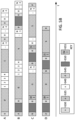
- FIG. 5A illustrates a worst-case latency scenario for a high priority frame according to a previously described method 505 of US 2019/0261420 A1 vs the present disclosure 510.
- low priority long frames 515, PLCA Beacon priority advertisement 520, and high priority short frames 525 are illustrated for a first method 505 and a second method 510.
- the previously described first method 505 allows the PHY device to advertise priorities of its frames once during a transmission cycle wherein the transmission cycle comprises transmission of a frame from each node in the network.
- Node 7 is a node that transmits high priority short frames. Node 7 realizes it needs to transmit a minimum sized high priority frame 525 one clock cycle after it advertised it currently had no frame to transmit but has to wait until the next opportunity to advertise as illustrated by ⁇ L and reference sign 503. In this case all the maximum sized low priority frames 515 from End Nodes 0 to 6 will be transmitted ahead of Node 7's high priority frame 525 because each normal PLCA Beacon starts transmission from Node 0 to Node N-1. After this long latency period, if Node 7 has accumulated more high priority frames 525 (e.g. two or more as illustrated FIG.
- One way to decrease the latency for high priority frames 525 is to reduce the transmission cycle to a single frame. This could also be described as increasing the number of advertising phases such that high priority frames get more opportunities to transmit.
- the PLCA network is replaced with an Ethernet switch in the above example of a first method 505, the highest priority frames would start transmitting after only one maximum sized Ethernet frame instead of N-1.
- the present disclosure aims to achieve the same behaviour/performance with PLCA, where 510 shows the worst-case latency improvement vs. 505 for a previously disclosed network example (of US 2019/0261420 A1 ).
- the presently disclosed method 510 provides the opportunity for Node 7 to advertise its high priority frame after transmission from Node 0 (at time 501), which is earlier than waiting for the full transmission cycle from Node 0 to Node N-1 (at time 503) according to the previous method 505.
- the method of the present disclosure 510 is an enhancement of the previous method 505.
- FIG. 5B illustrates PLCA cycles A, B, C and D.
- A is a regular PLCA cycle example
- B is PLCA with QoS ( US 2019/0261420 A1 )
- C is PLCA with lower latency QoS as described herein where the Coordinator keeps track of a single winning node that wins the advertisement and announces it to all Nodes
- D illustrates a PLCA with lower latency QoS according to an embodiment of the present disclosure where the wining node is also advertised as in C with the variation that the empty transmit opportunities that do not belong to the winning node are not part of the data phase cycle.
- PLCA cycle A comprises a first coordinator beacon 530 from Node 0 followed by transmission of data 535 from Node 0.
- Nodes 1 to 4 are silent 540 so do not make a transmission.
- Data is then transmitted 535 from Node 5. Note that in this example, the data 535 have the same and highest priority in this example.
- the remaining nodes up to Node N-1 are silent 540.
- the cycle then starts again with a coordinator beacon 530.
- PLCA cycle B comprises the addition of a priority advertisement beacon 545 followed by a priority advertisement 550 prior to the coordinator beacon 530. The remainder of the cycle follows the cycle as illustrated in PLCA cycle A.
- PLCA cycle C comprises the priority advertisement beacon 545 and priority advertisement 550 of PLCA cycle B, followed by a coordinator data beacon 530 (from Node 0) and further comprises winner information 555, which indicates that Node w won the advertisement.
- PLCA cycle D shows an embodiment of PLCA cycle C that does not spend any time during the cycle on silent nodes 540.
- a PLCA cycle method as illustrated by A in FIG. 5B is defined where each node transmits its next Ethernet frame in a round robin approach.
- the first PLCA cycle A illustrates the IEEE 802.3cg standardized PLCA method
- B illustrates the PLCA cycle as described in US 2019/0261420 A1 .
- FIG. 5B illustrates an N node network, with node IDs ranging from 0 to N-1.
- the indicated priority advertisement phase occurs in conjunction with the PLCA Beacon operation. In this way, each node knows the priority of all frames that the other nodes want to transmit such that only the highest advertised priority frames (and the priorities above it, if they just appeared in an End Nodes queues) are allowed to be transmitted during that PLCA Beacon cycle.
- Ethernet switches deliver (i.e., a worst-case latency of one maximum sized lower priority frame)
- the PLCA mechanism and its coordination with all the End Nodes needs to be enhanced to mimic what Ethernet switches do.
- the PLCA "network” can re-evaluate the priority of the next frame that all of the End Nodes want to transmit after every single frame is transmitted over the "network" (see FIG. 5B PLCA cycles C and D).
- State information can be kept so that fairness at each priority level is maintained between the End Nodes.
- the mechanism can be further enhanced to be robust against bit errors and the powering down and up of End Nodes.
- FIG. 5A shows the benefit of this mechanism, the magnitude of the reduced latency ( ⁇ L) for the high priority frame 525, and it shows the cost to attain this in terms of additional overhead ( ⁇ t) used on the networks segment.
- PLCA cycles C and D after every frame transmission from any node, mimics what each node's internal Tx path QoS Queues do (as shown in FIG. 3 ) and what Ethernet switches do as they use the same mechanism in their Tx path.
- One mechanism to maintain fairness between the PLCA End Nodes is to maintain state information about which End Node last transmitted a frame for each of the supported PLCA media priority levels ( US 2020/0067727 A1 defined support for more than eight priority levels). With this information, the next time a given priority level is determined to be the highest, the winning Node that gets to transmit is the next higher Node number than the last Node number that transmitted a frame at that priority level. The next higher Node number is calculated with wrapping such that an eight-node network where Node 6 was the last to transmit, the search order for the next winning Node number would be 7, 0, 1, 2, 3, 4, 5 and 6. In some examples, this order may be a predetermined sequence.
- Node 6 can be the next winner if no other Nodes want to transmit a frame at the winning priority level. Maintaining state information can also be used to determine which Node gets to transmit the next frame to the shared media in the case that there are two or more Nodes having a given priority frame to transmit (where "given" is the highest priority for all advertised frames). For example, if the most recent Node to transmit a frame to the shared media is Node 3, the next Node in the sequence would be Node 4 (if Node 4 has a frame to transmit that is of the given priority).
- Nodes 1 and 5 both have frames to transmit having a given priority
- the Node that would be chosen to transmit the next frame would be Node 5 (in the example that Node 3 was the last Node to transmit a frame to the shared media at the given priority), because Node 5 comes first according to the predetermined sequence comprising a round-robin approach.
- the transmit opportunities of the nodes that lost the arbitration could be omitted as another embodiment of this disclosure, as there can only be a single winner and all other TOs will just time out. This would remove the time-out durations.
- the PLCA Beacon "advertisement" phase (described in US 2019/0261420 A1 ) has each node, in Node number order starting from 0, advertise on the wire the priority of its next frame to transmit.
- each station gets a transmit opportunity, starting from Node 0 to Node N-1, where nodes that are not transmitting can sit idle such that after a silent time-out period, the next higher numbered node gets its opportunity (in US 2019/0261420 A1 , nodes that don't have a frame to transmit at the winning priority stay silent). In this way each node can know what Node number was the last one to transmit a frame at the winning priority and both pieces of information can be acquired by watching what occurs on the wire.
- the PLCA Beacon "advertisement" phase (described in US 2019/0261420 A1 ) is also used here but in this case only the Beacon generator node processes the received information from all the other nodes.
- the Beacon node determines a winning priority and the winning Node number by examining its local copy of the last winning Node number (for the winning priority).
- the Beacon generator then transmits a "winner" Beacon with the number of the Node that gets to transmit.
- the winning node transmits its frame and the Beacon generator updates its local copy of the last winning Node number and then starts a new Beacon "advertisement" phase.
- PLCA requires one and only one Beacon generator node
- this is the preferred node to keep the state information, as this node cannot be powered down unless all the nodes on the PLCA network are also powered down. In automotive this is an acceptable restriction to get the benefits of PLCA and the enhancements described here.
- the Beacon generator is the holder of the state information, it has the added job of indicating the winning node after each Advertisement beacon cycle. While this increases the size of the Advertisement beacon cycle, it saves time as the winning node can transmit immediately knowing it is the winner (i.e., the normal PLCA transmission opportunity timeouts can be skipped).
- the start-up procedure for the End Node has no historical state information but by definition, the End Node does not need any state information and the Beacon generator will tell it when it wins.
- the coordinator data beacon 530 could be omitted in further embodiments of this disclosure, to optimize the overhead the lower latency QoS variant of PLCA brings, in case the priority advertisement beacon 545 already is sufficient to synchronize all nodes. This is possible in case all nodes know how many nodes participate in the advertisement and can therefore determine when either the winner information 555 is sent or the data phase 535 begins. This embodiment could be linked to the embodiment when each End node maintains state information.
- the Transmit Opportunity (TO) of the nodes that lost the arbitration could be omitted as another embodiment, as there can only be a single winner and all other TOs will just time out. This would remove the time-out durations of the Transmit Opportunities of all nodes other than the winning node.
- This embodiment is especially suitable for the variant where only the Coordinator node maintains state information and communicates the winner, as there would be no ambiguity for each End Node with regards to the winner and there is less chance of a bus conflict. However, it can also be combined with the variant where all End Nodes maintain the state information.
- FIG. 5B PLCA cycle D illustrates an embodiment comprising the options as described above in relation to maintaining fairness at each Priority between End Nodes. It is the most optimal from a worst-case latency perspective for the highest priority frame on the bus, and the most robust.
- the present disclosure describes a mechanism and protocol to achieve PLCA Latency Improvements to QoS.
- the exact symbols/bits on the wire used to communicate this protocol are not defined here, as they may need to be different depending upon the environment, number of supported priorities, and/or the network size. That being said, the overhead can be closely estimated knowing the bits on the wire used for the normal PLCA Beacon.
- the present disclosure reduces the worst-case latency by approximately N multiplied by maximum frame length time, where N is the number of nodes in the network. This reduction is roughly in the order of 10k bit-times per node on the bus. This comes with the added cost of the advertisement phase, which is roughly in the order of tenths of bit-time per node on the bus. At 10Mbps, this means we get worst-case reductions in the order of milliseconds, at the cost of microseconds.
- the worst-case situation is defined as when there is a frame F that becomes available at time T at node X with the highest priority among all frames available on all the nodes on the bus, but will need to wait a worst-case scenario before node X may actually transmit on the PLCA bus at time T'.
- the worst-case latency is then T' -T, and is different per PLCA variant discussed below.
- the frame becomes available on the first node of the network, but has just missed its Transmit Opportunity, and all other N-1 nodes have the largest possible Ethernet frame to transmit.
- Frame F would have to wait for N-1 TOs, the Priority Advertisement Phase, and the Coordinator Beacon. This actually increases the worst-case latency compared to the Regular PLCA (cycle A) case with a single frame transmission per Transmit Opportunity.
- the frame becomes available just after the Transmit Opportunity of node X.
- Frame F then waits for the Priority Advertisement Phase, and the Coordinator Beacon.
- Table 1 Worst-case latency and overhead costs Worst-case latency for h ighest priority frame Advertisement phase latency Coordinator Beacon (data phase)
- Regular PLCA (no bursts) 8,635,700 ⁇ s 0 0.5 ⁇ s PLCA with QoS defined in PLCA cycle B 8,644,200 ⁇ s 8.5 ⁇ s 0.5 ⁇ s Present disclosure PLCA cycle D 1,251,100 ⁇ s 8.5 ⁇ s 1.0 ⁇ s
- Table 2 Latency improvements Latency improv of the worst-ca ements se Advertisement phase cost increase Co Bea ordinator con cost incr ease Delta of Present disclosure wrt regular PLCA 7,384,600 ⁇ s 8.5 ⁇ s 0.5 ⁇ s Delta of Present disclosure w
- Table 2 shows an overview of the latency improvements of the worst-case scenarios comparing the PLCA cycle illustrated in FIG. 5B PLCA cycle D to regular PLCA (PLCA cycle A), and to FIG. 5B PLCA cycle B. It also shows the cost increase in terms of latency caused by the overhead of adding advertising beacons. As mentioned earlier, and as shown in Table 2, the latency improvement in the worst-case scenarios are in the order of milliseconds, whereas the cost of overhead is in the order of microseconds.
Landscapes
- Engineering & Computer Science (AREA)
- Computer Networks & Wireless Communication (AREA)
- Signal Processing (AREA)
- Small-Scale Networks (AREA)
Priority Applications (1)
| Application Number | Priority Date | Filing Date | Title |
|---|---|---|---|
| EP22180845.4A EP4297348A1 (de) | 2022-06-23 | 2022-06-23 | Kollisionsvermeidung auf phy-ebene mit qos mit niedrigerer latenzzeit |
Applications Claiming Priority (1)
| Application Number | Priority Date | Filing Date | Title |
|---|---|---|---|
| EP22180845.4A EP4297348A1 (de) | 2022-06-23 | 2022-06-23 | Kollisionsvermeidung auf phy-ebene mit qos mit niedrigerer latenzzeit |
Publications (1)
| Publication Number | Publication Date |
|---|---|
| EP4297348A1 true EP4297348A1 (de) | 2023-12-27 |
Family
ID=82846267
Family Applications (1)
| Application Number | Title | Priority Date | Filing Date |
|---|---|---|---|
| EP22180845.4A Pending EP4297348A1 (de) | 2022-06-23 | 2022-06-23 | Kollisionsvermeidung auf phy-ebene mit qos mit niedrigerer latenzzeit |
Country Status (1)
| Country | Link |
|---|---|
| EP (1) | EP4297348A1 (de) |
Cited By (1)
| Publication number | Priority date | Publication date | Assignee | Title |
|---|---|---|---|---|
| EP4718785A1 (de) * | 2024-09-27 | 2026-04-01 | Nxp B.V. | Übertragung von ethernet-rahmen mit priorität |
Citations (2)
| Publication number | Priority date | Publication date | Assignee | Title |
|---|---|---|---|---|
| US20190261420A1 (en) | 2018-02-21 | 2019-08-22 | Nxp B.V. | Physical layer device that connects to a shared media and method for operating a physical layer device that connects to a shared media |
| US20200067727A1 (en) | 2018-08-27 | 2020-02-27 | Nxp B.V. | Physical layer device and method for operating a physical layer device |
-
2022
- 2022-06-23 EP EP22180845.4A patent/EP4297348A1/de active Pending
Patent Citations (2)
| Publication number | Priority date | Publication date | Assignee | Title |
|---|---|---|---|---|
| US20190261420A1 (en) | 2018-02-21 | 2019-08-22 | Nxp B.V. | Physical layer device that connects to a shared media and method for operating a physical layer device that connects to a shared media |
| US20200067727A1 (en) | 2018-08-27 | 2020-02-27 | Nxp B.V. | Physical layer device and method for operating a physical layer device |
Cited By (1)
| Publication number | Priority date | Publication date | Assignee | Title |
|---|---|---|---|---|
| EP4718785A1 (de) * | 2024-09-27 | 2026-04-01 | Nxp B.V. | Übertragung von ethernet-rahmen mit priorität |
Similar Documents
| Publication | Publication Date | Title |
|---|---|---|
| US10999099B2 (en) | Physical layer device and method for operating a physical layer device | |
| US11272543B2 (en) | Physical layer device that connects to a shared media and method for operating a physical layer device that connects to a shared media | |
| KR102398193B1 (ko) | 통신 채널을 통해 데이터를 전송하기 위한 방법, 상응하게 설계된 장치 및 통신 인터페이스, 및 상응하게 설계된 컴퓨터 프로그램 | |
| EP3166259B1 (de) | Robuste elektromagnetische kompatibilitätsleistung für fahrzeuginterne ethernet-phys mit verwendung von zeitmultiplexing | |
| CN107040361B (zh) | 基于车辆的时间信息对域进行时间同步的方法 | |
| EP1603283A2 (de) | Zugang zu einem gemeinsamen Kommunikationsmedium | |
| US11171807B2 (en) | Method and apparatus for allocating priority transmission opportunities in vehicle network | |
| CN106453148B (zh) | 网络中通信节点的操作方法 | |
| CN111466105B (zh) | 用于发送数据包的方法、控制设备和具有控制设备的系统 | |
| CN113994638A (zh) | 用于串行总线系统的用户站和用于在串行总线系统中进行通信的方法 | |
| JP2020150544A (ja) | 制約された環境における双方向通信の管理 | |
| US10602530B2 (en) | Access method with access slots and priority resolution | |
| EP4297348A1 (de) | Kollisionsvermeidung auf phy-ebene mit qos mit niedrigerer latenzzeit | |
| US11398925B2 (en) | Media access for time-sensitive and best efforts data packets, and related systems, methods and devices | |
| Min et al. | Performance enhancement of in-vehicle 10BASE-T1S ethernet using node prioritization and packet segmentation | |
| Min et al. | Interrupt-enabled physical layer collision avoidance for 10base-t1s automotive ethernet | |
| US20200344740A1 (en) | Method and apparatus for transmitting and receiving data stream performed in vehicle network | |
| CN120074982A (zh) | 用于串行总线系统中的确定性通信的用户站和方法 | |
| JP4909350B2 (ja) | メッセージの伝送方法 | |
| EP4312410A1 (de) | Can-kommunikationssteuerung und verfahren zum betrieb einer can-kommunikationssteuerung | |
| CN121750574A (zh) | 用于以太网节点的模块、以太网节点、通信系统和方法 |
Legal Events
| Date | Code | Title | Description |
|---|---|---|---|
| PUAI | Public reference made under article 153(3) epc to a published international application that has entered the european phase |
Free format text: ORIGINAL CODE: 0009012 |
|
| STAA | Information on the status of an ep patent application or granted ep patent |
Free format text: STATUS: THE APPLICATION HAS BEEN PUBLISHED |
|
| AK | Designated contracting states |
Kind code of ref document: A1 Designated state(s): AL AT BE BG CH CY CZ DE DK EE ES FI FR GB GR HR HU IE IS IT LI LT LU LV MC MK MT NL NO PL PT RO RS SE SI SK SM TR |
|
| STAA | Information on the status of an ep patent application or granted ep patent |
Free format text: STATUS: REQUEST FOR EXAMINATION WAS MADE |
|
| 17P | Request for examination filed |
Effective date: 20240627 |
|
| RBV | Designated contracting states (corrected) |
Designated state(s): AL AT BE BG CH CY CZ DE DK EE ES FI FR GB GR HR HU IE IS IT LI LT LU LV MC MK MT NL NO PL PT RO RS SE SI SK SM TR |