EP4297329A2 - Verfahren zum betrieb eines kommunikationssystems - Google Patents
Verfahren zum betrieb eines kommunikationssystems Download PDFInfo
- Publication number
- EP4297329A2 EP4297329A2 EP23209412.8A EP23209412A EP4297329A2 EP 4297329 A2 EP4297329 A2 EP 4297329A2 EP 23209412 A EP23209412 A EP 23209412A EP 4297329 A2 EP4297329 A2 EP 4297329A2
- Authority
- EP
- European Patent Office
- Prior art keywords
- slave
- uplink
- node
- slave nodes
- downlink
- Prior art date
- Legal status (The legal status is an assumption and is not a legal conclusion. Google has not performed a legal analysis and makes no representation as to the accuracy of the status listed.)
- Granted
Links
Images


Classifications
-
- H—ELECTRICITY
- H04—ELECTRIC COMMUNICATION TECHNIQUE
- H04W—WIRELESS COMMUNICATION NETWORKS
- H04W72/00—Local resource management
- H04W72/12—Wireless traffic scheduling
- H04W72/1263—Mapping of traffic onto schedule, e.g. scheduled allocation or multiplexing of flows
-
- H—ELECTRICITY
- H04—ELECTRIC COMMUNICATION TECHNIQUE
- H04L—TRANSMISSION OF DIGITAL INFORMATION, e.g. TELEGRAPHIC COMMUNICATION
- H04L1/00—Arrangements for detecting or preventing errors in the information received
- H04L1/12—Arrangements for detecting or preventing errors in the information received by using return channel
- H04L1/16—Arrangements for detecting or preventing errors in the information received by using return channel in which the return channel carries supervisory signals, e.g. repetition request signals
- H04L1/18—Automatic repetition systems, e.g. Van Duuren systems
- H04L1/1867—Arrangements specially adapted for the transmitter end
- H04L1/1887—Scheduling and prioritising arrangements
-
- H—ELECTRICITY
- H04—ELECTRIC COMMUNICATION TECHNIQUE
- H04L—TRANSMISSION OF DIGITAL INFORMATION, e.g. TELEGRAPHIC COMMUNICATION
- H04L1/00—Arrangements for detecting or preventing errors in the information received
- H04L1/004—Arrangements for detecting or preventing errors in the information received by using forward error control
- H04L1/0075—Transmission of coding parameters to receiver
-
- H—ELECTRICITY
- H04—ELECTRIC COMMUNICATION TECHNIQUE
- H04L—TRANSMISSION OF DIGITAL INFORMATION, e.g. TELEGRAPHIC COMMUNICATION
- H04L1/00—Arrangements for detecting or preventing errors in the information received
- H04L1/08—Arrangements for detecting or preventing errors in the information received by repeating transmission, e.g. Verdan system
-
- H—ELECTRICITY
- H04—ELECTRIC COMMUNICATION TECHNIQUE
- H04L—TRANSMISSION OF DIGITAL INFORMATION, e.g. TELEGRAPHIC COMMUNICATION
- H04L5/00—Arrangements affording multiple use of the transmission path
- H04L5/14—Two-way operation using the same type of signal, i.e. duplex
- H04L5/1469—Two-way operation using the same type of signal, i.e. duplex using time-sharing
-
- H—ELECTRICITY
- H04—ELECTRIC COMMUNICATION TECHNIQUE
- H04W—WIRELESS COMMUNICATION NETWORKS
- H04W72/00—Local resource management
- H04W72/04—Wireless resource allocation
- H04W72/044—Wireless resource allocation based on the type of the allocated resource
- H04W72/0446—Resources in time domain, e.g. slots or frames
-
- H—ELECTRICITY
- H04—ELECTRIC COMMUNICATION TECHNIQUE
- H04W—WIRELESS COMMUNICATION NETWORKS
- H04W72/00—Local resource management
- H04W72/20—Control channels or signalling for resource management
-
- H—ELECTRICITY
- H04—ELECTRIC COMMUNICATION TECHNIQUE
- H04W—WIRELESS COMMUNICATION NETWORKS
- H04W72/00—Local resource management
- H04W72/50—Allocation or scheduling criteria for wireless resources
- H04W72/54—Allocation or scheduling criteria for wireless resources based on quality criteria
- H04W72/542—Allocation or scheduling criteria for wireless resources based on quality criteria using measured or perceived quality
-
- H—ELECTRICITY
- H04—ELECTRIC COMMUNICATION TECHNIQUE
- H04L—TRANSMISSION OF DIGITAL INFORMATION, e.g. TELEGRAPHIC COMMUNICATION
- H04L1/00—Arrangements for detecting or preventing errors in the information received
- H04L2001/0092—Error control systems characterised by the topology of the transmission link
- H04L2001/0093—Point-to-multipoint
-
- H—ELECTRICITY
- H04—ELECTRIC COMMUNICATION TECHNIQUE
- H04L—TRANSMISSION OF DIGITAL INFORMATION, e.g. TELEGRAPHIC COMMUNICATION
- H04L1/00—Arrangements for detecting or preventing errors in the information received
- H04L2001/0092—Error control systems characterised by the topology of the transmission link
- H04L2001/0097—Relays
Definitions
- the invention relates to methods of operating a communication system in a time-division multiplexing technique as well as to communication nodes that are configured to be operated accordingly.
- ARQ automatic repeat request
- the international patent application WO 2017/157663 A1 discloses a method of operating a communication system that comprises at least four communication nodes.
- the communication system is operated in a time-division multiplexing technique wherein the communication is carried out in consecutive time frames which are divided into slots.
- At least one slot is allocated to each of the communication nodes.
- Each of the slots comprises, or preferably consists of, at least two consecutive sub-slots. Echo signals are transmitted during echo sub-slots.
- An objective of the present invention is to provide a very reliable method for operating a communication system.
- a further objective of the present invention is to provide an improved communication node with regard to a reliable communication.
- An embodiment of the present invention relates to a method of operating a communication system that comprises a master node and at least two slave nodes and is operated in a time-division multiplexing technique.
- the method is characterized in that the communication is carried out in consecutive time frames, which each comprise at least one transmission subframe and at least one auxiliary subframe which is scheduled after the transmission subframe.
- the transmission subframe comprises at least one downlink slot for transmission of downlink data packets from the master node to the slave nodes, and at least one uplink slot for transmission of uplink data packets from each of the slave nodes to the master node.
- the master node sends downlink data packets to all or at least a subset of the slave nodes during the downlink slot, and each of the slave nodes sends at least one uplink data packet to the master node during its respective uplink slot.
- the master node evaluates the uplink data packets that were received from the slave nodes during the uplink slots of the transmission subframe, and generates a re-transmission schedule that defines a re-transmission of uplink and/or downlink data packets in the auxiliary subframe in case of an unsuccessful reception of due uplink data packets from slave nodes in the respective uplink slot or in case that uplink data packets received from the slave nodes indicate an unsuccessful reception of downlink data packets during the previous downlink slot.
- the master node Prior to the first re-transmission of uplink and/or downlink data packets in the auxiliary subframe, the master node broadcasts the re-transmission schedule to the slave nodes.
- the master node preferably broadcasts the re-transmission schedule in a control packet between the transmission subframe and the auxiliary subframe.
- the re-transmission schedule may define at least one slave node that is requested to re-transmit the re-transmission schedule or the control packet before the beginning of or during the auxiliary subframe.
- each slave node In case of a successful reception of data packets from the master node in the downlink slot, each slave node preferably confirms this successful reception in its consecutive uplink slot.
- the re-transmission schedule may indicate that the master node itself re-transmits the respective downlink data packet to the affected slave node.
- Each of the slave nodes preferably store all uplink and downlink data packets that they receive during the transmission subframe, including those data packets that are assigned to other slave nodes or sent from other slave nodes to the master node.
- the re-transmission schedule may request one or more of the other slave nodes to re-transmit the respective stored downlink data packet.
- the re-transmission schedule may request one or more of the other slave nodes to re-transmit the respective stored uplink data packet.
- the selection of said one or more of the other slave nodes that are requested to re-transmit stored data packets may be arbitrary or carried out according to a given selection scheme that is independent of channel quality data.
- the master node preferably selects said one or more of the other slave nodes that are requested to re-transmit their stored data packets, in dependence of channel quality data.
- Each of the slave nodes may determine channel quality data with respect to data packets received from each of the other slave nodes as well as from the master node, and transmit the quality data to the master node during its uplink slot.
- the master node may request at least one of the other slave nodes, hereinafter referred to as uplink re-transmitting slave node, to re-transmit their respective stored uplink data packet, wherein the master node may select the slave node that has the best channel quality data with respect to the reception of data packets from the master node, as the or one of the uplink re-transmitting slave nodes.
- the master node may request at least one of the other slave nodes, hereinafter referred to as downlink re-transmitting slave node, to re-transmit their stored data packet of the respective downlink slot, wherein the master node may select at least the slave node that has the best channel quality data with respect to the reception of data packets from the affected node, as the or one of the downlink re-transmitting slave node.
- the master node preferably re-arranges the allocation of slave nodes to the uplink slots in the transmission subframe, wherein slave nodes having better channel quality data with respect to the reception of data packets from the master node are scheduled after slave nodes with worse channel quality data.
- the master node may determine at least one of the other slave nodes, hereinafter referred to as elected slave node, that has received and stored the data packets of both the downlink slot and uplink slot of the affected slave node, and may request the elected slave node within the re-transmission schedule to re-transmit the stored data packets of the respective downlink slot and uplink slot of the affected slave node.
- the elected slave node may generate a network-coded data packet based on the data packets of the downlink and uplink slot of the affected slave node.
- the network coding is preferably carried out based on a coding scheme that allows decoding the coded data on the basis of the data packet or packets of the uplink slot as well as on the basis of the data packet or packets of the downlink slot.
- the elected slave may broadcast the network-coded data according to the re-transmission schedule.
- the elected slave node preferably generates the network-coded data by applying an XOR-operation to the data packets of the downlink and uplink slot of the affected slave node.
- the master node may predict the number of slots that need to be re-transmitted in an upcoming time frame, e.g. in the next time frame, adapt the length of the auxiliary subframe of said upcoming time frame according to this prediction, and inform the slave nodes about the adapted length of the auxiliary subframe at least prior to the beginning of the auxiliary subframe of the respective time frame.
- the master node may predict the number of slots that need to be re-transmitted in the consecutive auxiliary subframe, during the ongoing transmission subframe, adapt the length of the auxiliary subframe according to this prediction, and inform the slave nodes about the adapted length of the auxiliary subframe at least prior to the beginning of the auxiliary subframe of the respective time frame.
- a further embodiment of the invention relates to a communication node configured to be part of a communication system that comprises a master node and at least two slave nodes.
- the communication node is preferably configured to operate either as master node or as slave node as described above.
- the communication node preferably comprises a processor and a memory.
- the memory stores a software module.
- the software module is configured such that the communication node operates either as master or slave node when the processor executes the software module.
- aspects of the above embodiments of the present invention are based on the assessment that ultra-reliable wireless systems can be expected to operate all their payload transmissions at relatively high reliability levels (exploiting diversity), such that out of N transmission attempts for N different stations, only a small fraction of stations will have to be re-transmitted.
- the exemplary embodiments of the present invention as described above therefore relate to ways how to increase the efficiency of such ultra-reliable wireless communication systems.
- the main idea here is to consider the re-transmissions not individually, but over a group of nodes which are all allocated with their transmissions (down-link as well as up-link) in a TDM, e.g. TDMA, time frame. Then, ultra-reliability can still be preserved if only for a subset of these nodes re-transmission slots are reserved, which nevertheless are allocated dynamically towards the end of a transmission subframe.
- N 10
- Such a dynamic organization of the packet re-transmissions by a master has further advantages. For instance, this organization allows to exploit instantaneous channel state information in the organization of the re-transmissions.
- this organization allows to exploit instantaneous channel state information in the organization of the re-transmissions.
- each station tracks the channel state from the transmitting station to itself, which is also done by the master (i.e. it tracks the channel state of the transmitting station).
- this station then appends the successful reception of all previous n-1 transmissions to the payload packet, while also appending the measured n-1 channel states.
- the efficiency of the dynamic re-transmission phase can thus be increased as the master knows to some degree which other stations correctly received some of the transmitted payload packets, and how good their wireless channel states are (among each other as well as towards the master). Therefore, instead of dynamically scheduling the re-transmission from the original node of the corresponding payload, the master can schedule the re-transmission to be performed by an intermediate node that received the payload correctly, and which has a better channel state towards the master. In many cases this can drastically increase the reliability of the system, in comparison to re-transmissions being conducted by the original nodes, such that even less re-transmission slots at the end of the TDMA frame need to be reserved.
- FIG 1 shows an exemplary embodiment of a communication system 10 according to the present invention.
- the communication system 10 comprises a master node MN and a plurality of slave nodes SN1-SN4, for instance four slave nodes SN1-SN4 as shown in Figure 1 .
- the master node MN communicates with the slave nodes SN1-SN4 preferably via radio signals RS.
- the communication system is operated in a time-division multiplexing technique wherein the communication is carried out in consecutive time frames F.
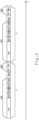
- a first exemplary embodiment of a time frame F is depicted in Figure 2 .
- the time frame F comprises a transmission subframe TSF, an auxiliary subframe ASF and a control slot Sjsp for transmitting a control packet JSP.
- the auxiliary subframe ASF comprises two re-transmission slots RT and is scheduled after the transmission subframe TSF.
- the control slot Sjsp is scheduled between the transmission subframe TSF and the auxiliary subframe ASF.
- the transmission subframe TSF of Figure 2 comprises a downlink slot DS for transmission of downlink data packets DDP (see step 100 in Figure 3 ) from the master node MN to the slave nodes SN1-SN4, and uplink slots US1-US4 for transmission of uplink data packets UDP (see step 110 in Figure 3 ) from each of the slave nodes SN1-SN4 to the master node MN.
- the uplink slot US1 is assigned to the slave node SN1
- the uplink slot US2 is assigned to the slave node SN2
- the uplink slot US3 is assigned to the slave node SN3
- the uplink slots US4 is assigned to the slave node SN4.
- the communication system of Figure 1 may be operated as shown in the flowchart of Figure 3 :
- the master node MN sends downlink data packets DDP to all or at least a subset of the slave nodes SN1-SN4 (see step 100 in Figure 3 ).
- each slave node SN1-SN4 sends at least one uplink data packet UDP to the master node MN during its respective uplink slot US1-US4 (see step 110 in Figure 3 ).
- the uplink data packets UDP sent by the slave nodes confirm this successful reception.
- the slave nodes SN1-SN4 report the missing or failed transmission in their respective uplink data packets UDP.
- the slave nodes SN1-SN4 preferably store all the downlink data packets DDP as well as all uplink data packets UDP that they receive during the transmission subframe TSF, including those data packets that are assigned to other slave nodes or sent from other slave nodes to the master node MN.
- the slave nodes SN1-SN4 preferably inform the master node MN about all received and stored data packets. As will be explained further below, the information regarding stored data packets allows the master node to schedule an indirect re-transmission of data packets through intermediate slave nodes.
- the slave nodes SN1-SN4 preferably determine channel quality data with respect to data packets UDP and DDP received from the other nodes.
- the slave nodes preferably transmit the quality data to the master node MN.
- the information regarding channel quality data allows the master node to determine the most suitable intermediate slave nodes for an indirect re-transmission of data packets.
- the master node MN evaluates the received uplink data packets UDP in step 120.
- the master node MN In case of an unsuccessful reception of due uplink data packets UDP from slave nodes SN1-SN4 in the respective uplink slot US1-US4 or in case that uplink data packets UDP indicate an unsuccessful reception of downlink data packets DDP during the previous downlink slot DS, the master node MN generates a re-transmission schedule RTS that defines a re-transmission of uplink data packets UDP and/or downlink data packets DDP in the upcoming auxiliary subframe ASF.
- step 130 the master node MN broadcasts the re-transmission schedule RTS to the slave nodes SN1-SN4.
- the re-transmission schedule RTS is incorporated in the control packet JSP and sent during the control slot Sjsp.
- the re-transmission schedule is preferably generated in dependence of the channel quality data that the slave nodes have transmitted to the master node. More specifically, the re-transmission schedule is preferably generated as follows:
- step 140 the slave nodes that have been appointed for a re-transmission, re-transmit downlink and uplink data packets in the re-transmission slots RT according to the re-transmission schedule as defined in the control packet JSP.
- the elected slave node preferably generates a network-coded data packet based on the data packets of both the downlink slot DS and the uplink slot of the affected slave node.
- the network coding is preferably carried out based on a coding scheme that allows decoding the coded data on the basis of the data packet or packets of the uplink slot as well as on the basis of the data packet or packets of the downlink slot DS.
- the elected slave node may generate the network-coded data by applying an XOR-operation to the data packets of the downlink slot and the uplink slot of the affected slave node. The elected slave node then broadcasts the network-coded data according to the re-transmission schedule.
- the length of the time frame F, the length of the transmission subframe TSF, the length of the auxiliary subframe ASF (e.g. the number of re-transmission slots RT) and the length of the control slot Sjsp is preferably constant in order to allow the nodes to synchronize their transmission relative to one another and transmit their data during the appropriate slots and at the appropriate moment in time.
- the auxiliary subframe ASF comprises two re-transmission slots RT.
- the master node MN may modify the length of the auxiliary subframe ASF and the number of re-transmission slots RT.
- the master node MN may evaluate one or more previous time frames F and adjust the number of re-transmission slots. For instance, the master node MN may predict the number of slots that need to be re-transmitted in an upcoming time frame F, e.g. in the next time frame F, adapt the length of the auxiliary subframe ASF of said upcoming time frame F according to this prediction, and inform the slave nodes SN1-SN4 about the adapted length of the auxiliary subframe ASF.
- the information is transmitted preferably at least prior to the beginning of the following time frame F.
- the master node MN may predict the number of slots that need to be re-transmitted during the ongoing transmission subframe TSF.
- the information regarding the length of the auxiliary subframe ASF should be transmitted at least prior to the beginning of the auxiliary subframe ASF of the respective time frame F.
- the master node MN may re-arrange the allocation of slave nodes SN1-SN4 to the uplink slots US1-US4 in the transmission subframe TSF.
- slave nodes SN1-SN4 having better channel quality data with respect to the reception of data packets from the master node MN are scheduled after slave nodes SN1-SN4 with worse channel quality data.
- the master node may inform the new allocation during its downlink slot DS. If the master node groups better nodes (with respect to the channel quality data) after worse nodes (with respect to the channel quality data), the likelihood increases that slave nodes may be able to re-transmit data from other slave nodes.
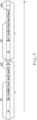
- Figure 4 shows a second exemplary embodiment of a time frame F that is suitable for the operation of a communication system according to the present invention.
- the time frame F of Figure 4 comprises two control slots Sjsp1 und Sjsp2. Both control slots are scheduled between the transmission subframe TSF and the auxiliary subframe ASF.
- the master node broadcasts the control packet JSP and publishes the re-transmission schedule RTS as explained above with reference to Figures 1-3 .
- the control packet JSP defines at least one slave node, hereinafter referred to as repeater node, that is requested to re-transmit the re-transmission schedule RTS or the entire control packet in the second control slot Sjsp2.
- the re-transmission of the re-transmission schedule RTS or the entire control packet JSP increases the likelihood that all slave nodes receive the re-transmission schedule RTS.
- the master node MN may determine the repeater node or one of the repeater nodes as follows: First, the master node determines the slave node that has the worst connection with the master node (e.g. based on the known channel quality data). The slave node that has the best connection with the latter slave node, is then selected as the repeating node.
- the re-transmission of the re-transmission schedule RTS or the entire control packet JSP is then carried out by the repeater slave node(s) that are identified in the control packet JSP.
- the spare slots may be filled with best effort data.
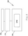
- FIG. 6 shows an exemplary embodiment of communication node 300 according to the present invention.
- the communication node 300 comprises a processor 310, a memory 320, and a transceiver 330 that is controlled by the processor 310.
- the memory 320 stores a software module SPM.
- the software module SPM is configured such that the communication node 300 operates either as master or slave node when the processor 310 executes the software module SPM.
Landscapes
- Engineering & Computer Science (AREA)
- Signal Processing (AREA)
- Computer Networks & Wireless Communication (AREA)
- Quality & Reliability (AREA)
- Mobile Radio Communication Systems (AREA)
- Detection And Prevention Of Errors In Transmission (AREA)
- Time-Division Multiplex Systems (AREA)
- Small-Scale Networks (AREA)
Applications Claiming Priority (3)
| Application Number | Priority Date | Filing Date | Title |
|---|---|---|---|
| EP19160020.4A EP3703288A1 (de) | 2019-02-28 | 2019-02-28 | Verfahren zum betrieb eines kommunikationssystems |
| PCT/EP2020/053889 WO2020173718A1 (en) | 2019-02-28 | 2020-02-14 | Method of operating a communication system |
| EP20707194.5A EP3931993B1 (de) | 2019-02-28 | 2020-02-14 | Verfahren zum betrieb eines kommunikationssystems |
Related Parent Applications (2)
| Application Number | Title | Priority Date | Filing Date |
|---|---|---|---|
| EP20707194.5A Division-Into EP3931993B1 (de) | 2019-02-28 | 2020-02-14 | Verfahren zum betrieb eines kommunikationssystems |
| EP20707194.5A Division EP3931993B1 (de) | 2019-02-28 | 2020-02-14 | Verfahren zum betrieb eines kommunikationssystems |
Publications (4)
| Publication Number | Publication Date |
|---|---|
| EP4297329A2 true EP4297329A2 (de) | 2023-12-27 |
| EP4297329A3 EP4297329A3 (de) | 2024-03-06 |
| EP4297329C0 EP4297329C0 (de) | 2025-04-23 |
| EP4297329B1 EP4297329B1 (de) | 2025-04-23 |
Family
ID=65635575
Family Applications (4)
| Application Number | Title | Priority Date | Filing Date |
|---|---|---|---|
| EP19160020.4A Withdrawn EP3703288A1 (de) | 2019-02-28 | 2019-02-28 | Verfahren zum betrieb eines kommunikationssystems |
| EP20707194.5A Active EP3931993B1 (de) | 2019-02-28 | 2020-02-14 | Verfahren zum betrieb eines kommunikationssystems |
| EP23209412.8A Active EP4297329B1 (de) | 2019-02-28 | 2020-02-14 | Verfahren zum betrieb eines kommunikationssystems |
| EP23209419.3A Active EP4304127B1 (de) | 2019-02-28 | 2020-02-14 | Verfahren zum betrieb eines kommunikationssystems |
Family Applications Before (2)
| Application Number | Title | Priority Date | Filing Date |
|---|---|---|---|
| EP19160020.4A Withdrawn EP3703288A1 (de) | 2019-02-28 | 2019-02-28 | Verfahren zum betrieb eines kommunikationssystems |
| EP20707194.5A Active EP3931993B1 (de) | 2019-02-28 | 2020-02-14 | Verfahren zum betrieb eines kommunikationssystems |
Family Applications After (1)
| Application Number | Title | Priority Date | Filing Date |
|---|---|---|---|
| EP23209419.3A Active EP4304127B1 (de) | 2019-02-28 | 2020-02-14 | Verfahren zum betrieb eines kommunikationssystems |
Country Status (6)
| Country | Link |
|---|---|
| US (1) | US12120663B2 (de) |
| EP (4) | EP3703288A1 (de) |
| JP (1) | JP7508468B2 (de) |
| CN (1) | CN113412591A (de) |
| ES (1) | ES2972040T3 (de) |
| WO (1) | WO2020173718A1 (de) |
Families Citing this family (1)
| Publication number | Priority date | Publication date | Assignee | Title |
|---|---|---|---|---|
| CN115348548B (zh) * | 2022-08-11 | 2024-08-02 | 无锡中感微电子股份有限公司 | 音频广播方法、装置、系统、电子设备及可读存储介质 |
Citations (1)
| Publication number | Priority date | Publication date | Assignee | Title |
|---|---|---|---|---|
| WO2017157663A1 (en) | 2016-03-17 | 2017-09-21 | R3 - Reliable Realtime Radio Communications Gmbh | Communication system |
Family Cites Families (9)
| Publication number | Priority date | Publication date | Assignee | Title |
|---|---|---|---|---|
| JP2000069547A (ja) | 1998-08-26 | 2000-03-03 | Nippon Telegr & Teleph Corp <Ntt> | 無線通信装置 |
| US7133396B1 (en) | 2000-03-06 | 2006-11-07 | Texas Instruments Incorporated | Dynamic assignment of retransmission slots for enhanced quality in wireless communication links |
| US7190686B1 (en) * | 2000-12-20 | 2007-03-13 | Cisco Technology, Inc. | Self configuring high throughput medium access control for wireless networks |
| US8842611B2 (en) * | 2010-03-03 | 2014-09-23 | Nokia Corporation | Compressed hybrid automatic repeat request feedback for device to device cluster communications |
| JP5764197B2 (ja) * | 2010-04-07 | 2015-08-12 | コーニンクレッカ フィリップス エヌ ヴェ | モバイル・ネットワークにおいて通信するための方法 |
| CN103546254B (zh) * | 2012-07-09 | 2017-09-15 | 财团法人工业技术研究院 | 执行混合式自动重送请求的方法及其基站与移动装置 |
| WO2014014165A1 (en) | 2012-07-15 | 2014-01-23 | Lg Electronics Inc. | Method for transmitting downlink signal at a relay node in a wireless communication system and appatatus therefor |
| US10342012B2 (en) * | 2015-03-15 | 2019-07-02 | Qualcomm Incorporated | Self-contained time division duplex (TDD) subframe structure |
| US10673577B2 (en) * | 2018-07-24 | 2020-06-02 | Kabushiki Kaisha Toshiba | Method for efficient retransmissions in multi-hop control networks |
-
2019
- 2019-02-28 EP EP19160020.4A patent/EP3703288A1/de not_active Withdrawn
-
2020
- 2020-02-14 EP EP20707194.5A patent/EP3931993B1/de active Active
- 2020-02-14 US US17/433,432 patent/US12120663B2/en active Active
- 2020-02-14 CN CN202080011896.7A patent/CN113412591A/zh active Pending
- 2020-02-14 ES ES20707194T patent/ES2972040T3/es active Active
- 2020-02-14 EP EP23209412.8A patent/EP4297329B1/de active Active
- 2020-02-14 EP EP23209419.3A patent/EP4304127B1/de active Active
- 2020-02-14 WO PCT/EP2020/053889 patent/WO2020173718A1/en not_active Ceased
- 2020-02-14 JP JP2021549358A patent/JP7508468B2/ja active Active
Patent Citations (1)
| Publication number | Priority date | Publication date | Assignee | Title |
|---|---|---|---|---|
| WO2017157663A1 (en) | 2016-03-17 | 2017-09-21 | R3 - Reliable Realtime Radio Communications Gmbh | Communication system |
Also Published As
| Publication number | Publication date |
|---|---|
| EP3931993B1 (de) | 2023-12-20 |
| EP3931993A1 (de) | 2022-01-05 |
| WO2020173718A1 (en) | 2020-09-03 |
| ES2972040T3 (es) | 2024-06-10 |
| US20220167377A1 (en) | 2022-05-26 |
| EP4304127A3 (de) | 2024-03-06 |
| CN113412591A (zh) | 2021-09-17 |
| EP4304127B1 (de) | 2025-05-07 |
| JP2022521928A (ja) | 2022-04-13 |
| EP4304127A2 (de) | 2024-01-10 |
| EP4297329C0 (de) | 2025-04-23 |
| EP3703288A1 (de) | 2020-09-02 |
| EP4297329A3 (de) | 2024-03-06 |
| US12120663B2 (en) | 2024-10-15 |
| JP7508468B2 (ja) | 2024-07-01 |
| EP4304127C0 (de) | 2025-05-07 |
| EP4297329B1 (de) | 2025-04-23 |
| EP3931993C0 (de) | 2023-12-20 |
Similar Documents
| Publication | Publication Date | Title |
|---|---|---|
| US12219585B2 (en) | Method for transmitting data or control information having high reliability conditions, and device therefor | |
| US11917651B2 (en) | Method for transmitting data or control information having high reliability conditions, and device therefor | |
| US5931964A (en) | Method and arrangement for channel allocation in a radio communications system | |
| US8149757B2 (en) | Bandwidth efficient HARQ scheme in relay network | |
| KR102429823B1 (ko) | 비-지상 통신들을 위한 시스템 | |
| KR100882057B1 (ko) | 통신 제어 방법, 무선 통신 시스템, 기지국, 이동국 및 컴퓨터 판독 가능 기록 매체 | |
| US20050041588A1 (en) | Apparatus and method for assigning channel in a mobile communication system using HARQ | |
| KR20160036458A (ko) | 단말간 통신의 harq 처리 방법 및 장치 | |
| US7715361B2 (en) | Apparatus and method for transmitting/receiving a downlink signal in a communication system | |
| EP4304127B1 (de) | Verfahren zum betrieb eines kommunikationssystems | |
| JP2004253828A (ja) | 無線送信装置及び無線送信方法 | |
| WO2012071872A1 (zh) | 数据传输方法及通信节点 | |
| US12375207B2 (en) | Handling of re-transmissions in a wireless communication network | |
| US8392782B2 (en) | Apparatus and method for processing auto repeat request in multiple input multiple output system | |
| US8275383B2 (en) | System for ranging based on partitioned radio resource | |
| KR101603574B1 (ko) | 수신 성공 여부 전송 시스템 | |
| US20090303959A1 (en) | Base Station And Frequency Changing Method In Mobile Communication System | |
| HK40025372A (en) | Method and apparatus for communicating on uplink and method and apparatus for receiving data on uplink |
Legal Events
| Date | Code | Title | Description |
|---|---|---|---|
| PUAI | Public reference made under article 153(3) epc to a published international application that has entered the european phase |
Free format text: ORIGINAL CODE: 0009012 |
|
| STAA | Information on the status of an ep patent application or granted ep patent |
Free format text: STATUS: THE APPLICATION HAS BEEN PUBLISHED |
|
| AC | Divisional application: reference to earlier application |
Ref document number: 3931993 Country of ref document: EP Kind code of ref document: P |
|
| AK | Designated contracting states |
Kind code of ref document: A2 Designated state(s): AL AT BE BG CH CY CZ DE DK EE ES FI FR GB GR HR HU IE IS IT LI LT LU LV MC MK MT NL NO PL PT RO RS SE SI SK SM TR |
|
| REG | Reference to a national code |
Ref country code: DE Ref legal event code: R079 Free format text: PREVIOUS MAIN CLASS: H04L0005140000 Ipc: H04L0001000000 Ref document number: 602020050256 Country of ref document: DE |
|
| PUAL | Search report despatched |
Free format text: ORIGINAL CODE: 0009013 |
|
| AK | Designated contracting states |
Kind code of ref document: A3 Designated state(s): AL AT BE BG CH CY CZ DE DK EE ES FI FR GB GR HR HU IE IS IT LI LT LU LV MC MK MT NL NO PL PT RO RS SE SI SK SM TR |
|
| RIC1 | Information provided on ipc code assigned before grant |
Ipc: H04L 1/1867 20230101ALI20240131BHEP Ipc: H04L 5/14 20060101ALI20240131BHEP Ipc: H04L 1/00 20060101AFI20240131BHEP |
|
| STAA | Information on the status of an ep patent application or granted ep patent |
Free format text: STATUS: REQUEST FOR EXAMINATION WAS MADE |
|
| 17P | Request for examination filed |
Effective date: 20240821 |
|
| RBV | Designated contracting states (corrected) |
Designated state(s): AL AT BE BG CH CY CZ DE DK EE ES FI FR GB GR HR HU IE IS IT LI LT LU LV MC MK MT NL NO PL PT RO RS SE SI SK SM TR |
|
| GRAP | Despatch of communication of intention to grant a patent |
Free format text: ORIGINAL CODE: EPIDOSNIGR1 |
|
| STAA | Information on the status of an ep patent application or granted ep patent |
Free format text: STATUS: GRANT OF PATENT IS INTENDED |
|
| RIC1 | Information provided on ipc code assigned before grant |
Ipc: H04L 1/1867 20230101ALI20241112BHEP Ipc: H04L 5/14 20060101ALI20241112BHEP Ipc: H04L 1/00 20060101AFI20241112BHEP |
|
| INTG | Intention to grant announced |
Effective date: 20241122 |
|
| GRAS | Grant fee paid |
Free format text: ORIGINAL CODE: EPIDOSNIGR3 |
|
| GRAA | (expected) grant |
Free format text: ORIGINAL CODE: 0009210 |
|
| STAA | Information on the status of an ep patent application or granted ep patent |
Free format text: STATUS: THE PATENT HAS BEEN GRANTED |
|
| AC | Divisional application: reference to earlier application |
Ref document number: 3931993 Country of ref document: EP Kind code of ref document: P |
|
| AK | Designated contracting states |
Kind code of ref document: B1 Designated state(s): AL AT BE BG CH CY CZ DE DK EE ES FI FR GB GR HR HU IE IS IT LI LT LU LV MC MK MT NL NO PL PT RO RS SE SI SK SM TR |
|
| REG | Reference to a national code |
Ref country code: GB Ref legal event code: FG4D |
|
| REG | Reference to a national code |
Ref country code: CH Ref legal event code: EP |
|
| REG | Reference to a national code |
Ref country code: DE Ref legal event code: R096 Ref document number: 602020050256 Country of ref document: DE |
|
| REG | Reference to a national code |
Ref country code: IE Ref legal event code: FG4D |
|
| U01 | Request for unitary effect filed |
Effective date: 20250515 |
|
| U07 | Unitary effect registered |
Designated state(s): AT BE BG DE DK EE FI FR IT LT LU LV MT NL PT RO SE SI Effective date: 20250521 |
|
| PG25 | Lapsed in a contracting state [announced via postgrant information from national office to epo] |
Ref country code: ES Free format text: LAPSE BECAUSE OF FAILURE TO SUBMIT A TRANSLATION OF THE DESCRIPTION OR TO PAY THE FEE WITHIN THE PRESCRIBED TIME-LIMIT Effective date: 20250423 |
|
| PG25 | Lapsed in a contracting state [announced via postgrant information from national office to epo] |
Ref country code: GR Free format text: LAPSE BECAUSE OF FAILURE TO SUBMIT A TRANSLATION OF THE DESCRIPTION OR TO PAY THE FEE WITHIN THE PRESCRIBED TIME-LIMIT Effective date: 20250724 Ref country code: NO Free format text: LAPSE BECAUSE OF FAILURE TO SUBMIT A TRANSLATION OF THE DESCRIPTION OR TO PAY THE FEE WITHIN THE PRESCRIBED TIME-LIMIT Effective date: 20250723 |
|
| PG25 | Lapsed in a contracting state [announced via postgrant information from national office to epo] |
Ref country code: PL Free format text: LAPSE BECAUSE OF FAILURE TO SUBMIT A TRANSLATION OF THE DESCRIPTION OR TO PAY THE FEE WITHIN THE PRESCRIBED TIME-LIMIT Effective date: 20250423 |
|
| PG25 | Lapsed in a contracting state [announced via postgrant information from national office to epo] |
Ref country code: HR Free format text: LAPSE BECAUSE OF FAILURE TO SUBMIT A TRANSLATION OF THE DESCRIPTION OR TO PAY THE FEE WITHIN THE PRESCRIBED TIME-LIMIT Effective date: 20250423 |
|
| PG25 | Lapsed in a contracting state [announced via postgrant information from national office to epo] |
Ref country code: RS Free format text: LAPSE BECAUSE OF FAILURE TO SUBMIT A TRANSLATION OF THE DESCRIPTION OR TO PAY THE FEE WITHIN THE PRESCRIBED TIME-LIMIT Effective date: 20250723 |
|
| PG25 | Lapsed in a contracting state [announced via postgrant information from national office to epo] |
Ref country code: IS Free format text: LAPSE BECAUSE OF FAILURE TO SUBMIT A TRANSLATION OF THE DESCRIPTION OR TO PAY THE FEE WITHIN THE PRESCRIBED TIME-LIMIT Effective date: 20250823 |
|
| PG25 | Lapsed in a contracting state [announced via postgrant information from national office to epo] |
Ref country code: SM Free format text: LAPSE BECAUSE OF FAILURE TO SUBMIT A TRANSLATION OF THE DESCRIPTION OR TO PAY THE FEE WITHIN THE PRESCRIBED TIME-LIMIT Effective date: 20250423 |
|
| PG25 | Lapsed in a contracting state [announced via postgrant information from national office to epo] |
Ref country code: CZ Free format text: LAPSE BECAUSE OF FAILURE TO SUBMIT A TRANSLATION OF THE DESCRIPTION OR TO PAY THE FEE WITHIN THE PRESCRIBED TIME-LIMIT Effective date: 20250423 |
|
| PG25 | Lapsed in a contracting state [announced via postgrant information from national office to epo] |
Ref country code: SK Free format text: LAPSE BECAUSE OF FAILURE TO SUBMIT A TRANSLATION OF THE DESCRIPTION OR TO PAY THE FEE WITHIN THE PRESCRIBED TIME-LIMIT Effective date: 20250423 |
|
| PLBE | No opposition filed within time limit |
Free format text: ORIGINAL CODE: 0009261 |
|
| STAA | Information on the status of an ep patent application or granted ep patent |
Free format text: STATUS: NO OPPOSITION FILED WITHIN TIME LIMIT |
|
| REG | Reference to a national code |
Ref country code: CH Ref legal event code: L10 Free format text: ST27 STATUS EVENT CODE: U-0-0-L10-L00 (AS PROVIDED BY THE NATIONAL OFFICE) Effective date: 20260304 |