EP4297141A1 - Porous frame-based solid electrolyte membrane, method for manufacturing same, and all-solid-state battery comprising same - Google Patents
Porous frame-based solid electrolyte membrane, method for manufacturing same, and all-solid-state battery comprising same Download PDFInfo
- Publication number
- EP4297141A1 EP4297141A1 EP22756544.7A EP22756544A EP4297141A1 EP 4297141 A1 EP4297141 A1 EP 4297141A1 EP 22756544 A EP22756544 A EP 22756544A EP 4297141 A1 EP4297141 A1 EP 4297141A1
- Authority
- EP
- European Patent Office
- Prior art keywords
- solid electrolyte
- porous frame
- mixture
- electrolyte membrane
- porous
- Prior art date
- Legal status (The legal status is an assumption and is not a legal conclusion. Google has not performed a legal analysis and makes no representation as to the accuracy of the status listed.)
- Pending
Links
Images


Classifications
-
- H—ELECTRICITY
- H01—ELECTRIC ELEMENTS
- H01M—PROCESSES OR MEANS, e.g. BATTERIES, FOR THE DIRECT CONVERSION OF CHEMICAL ENERGY INTO ELECTRICAL ENERGY
- H01M10/00—Secondary cells; Manufacture thereof
- H01M10/05—Accumulators with non-aqueous electrolyte
- H01M10/056—Accumulators with non-aqueous electrolyte characterised by the materials used as electrolytes, e.g. mixed inorganic/organic electrolytes
- H01M10/0561—Accumulators with non-aqueous electrolyte characterised by the materials used as electrolytes, e.g. mixed inorganic/organic electrolytes the electrolyte being constituted of inorganic materials only
- H01M10/0562—Solid materials
-
- H—ELECTRICITY
- H01—ELECTRIC ELEMENTS
- H01M—PROCESSES OR MEANS, e.g. BATTERIES, FOR THE DIRECT CONVERSION OF CHEMICAL ENERGY INTO ELECTRICAL ENERGY
- H01M10/00—Secondary cells; Manufacture thereof
- H01M10/05—Accumulators with non-aqueous electrolyte
- H01M10/056—Accumulators with non-aqueous electrolyte characterised by the materials used as electrolytes, e.g. mixed inorganic/organic electrolytes
- H01M10/0564—Accumulators with non-aqueous electrolyte characterised by the materials used as electrolytes, e.g. mixed inorganic/organic electrolytes the electrolyte being constituted of organic materials only
- H01M10/0565—Polymeric materials, e.g. gel-type or solid-type
-
- H—ELECTRICITY
- H01—ELECTRIC ELEMENTS
- H01M—PROCESSES OR MEANS, e.g. BATTERIES, FOR THE DIRECT CONVERSION OF CHEMICAL ENERGY INTO ELECTRICAL ENERGY
- H01M50/00—Constructional details or processes of manufacture of the non-active parts of electrochemical cells other than fuel cells, e.g. hybrid cells
- H01M50/40—Separators; Membranes; Diaphragms; Spacing elements inside cells
- H01M50/403—Manufacturing processes of separators, membranes or diaphragms
-
- H—ELECTRICITY
- H01—ELECTRIC ELEMENTS
- H01M—PROCESSES OR MEANS, e.g. BATTERIES, FOR THE DIRECT CONVERSION OF CHEMICAL ENERGY INTO ELECTRICAL ENERGY
- H01M50/00—Constructional details or processes of manufacture of the non-active parts of electrochemical cells other than fuel cells, e.g. hybrid cells
- H01M50/40—Separators; Membranes; Diaphragms; Spacing elements inside cells
- H01M50/409—Separators, membranes or diaphragms characterised by the material
- H01M50/411—Organic material
-
- H—ELECTRICITY
- H01—ELECTRIC ELEMENTS
- H01M—PROCESSES OR MEANS, e.g. BATTERIES, FOR THE DIRECT CONVERSION OF CHEMICAL ENERGY INTO ELECTRICAL ENERGY
- H01M50/00—Constructional details or processes of manufacture of the non-active parts of electrochemical cells other than fuel cells, e.g. hybrid cells
- H01M50/40—Separators; Membranes; Diaphragms; Spacing elements inside cells
- H01M50/409—Separators, membranes or diaphragms characterised by the material
- H01M50/431—Inorganic material
-
- H—ELECTRICITY
- H01—ELECTRIC ELEMENTS
- H01M—PROCESSES OR MEANS, e.g. BATTERIES, FOR THE DIRECT CONVERSION OF CHEMICAL ENERGY INTO ELECTRICAL ENERGY
- H01M50/00—Constructional details or processes of manufacture of the non-active parts of electrochemical cells other than fuel cells, e.g. hybrid cells
- H01M50/40—Separators; Membranes; Diaphragms; Spacing elements inside cells
- H01M50/409—Separators, membranes or diaphragms characterised by the material
- H01M50/449—Separators, membranes or diaphragms characterised by the material having a layered structure
-
- H—ELECTRICITY
- H01—ELECTRIC ELEMENTS
- H01M—PROCESSES OR MEANS, e.g. BATTERIES, FOR THE DIRECT CONVERSION OF CHEMICAL ENERGY INTO ELECTRICAL ENERGY
- H01M50/00—Constructional details or processes of manufacture of the non-active parts of electrochemical cells other than fuel cells, e.g. hybrid cells
- H01M50/40—Separators; Membranes; Diaphragms; Spacing elements inside cells
- H01M50/409—Separators, membranes or diaphragms characterised by the material
- H01M50/449—Separators, membranes or diaphragms characterised by the material having a layered structure
- H01M50/451—Separators, membranes or diaphragms characterised by the material having a layered structure comprising layers of only organic material and layers containing inorganic material
-
- H—ELECTRICITY
- H01—ELECTRIC ELEMENTS
- H01M—PROCESSES OR MEANS, e.g. BATTERIES, FOR THE DIRECT CONVERSION OF CHEMICAL ENERGY INTO ELECTRICAL ENERGY
- H01M50/00—Constructional details or processes of manufacture of the non-active parts of electrochemical cells other than fuel cells, e.g. hybrid cells
- H01M50/40—Separators; Membranes; Diaphragms; Spacing elements inside cells
- H01M50/489—Separators, membranes, diaphragms or spacing elements inside the cells, characterised by their physical properties, e.g. swelling degree, hydrophilicity or shut down properties
-
- H—ELECTRICITY
- H01—ELECTRIC ELEMENTS
- H01M—PROCESSES OR MEANS, e.g. BATTERIES, FOR THE DIRECT CONVERSION OF CHEMICAL ENERGY INTO ELECTRICAL ENERGY
- H01M50/00—Constructional details or processes of manufacture of the non-active parts of electrochemical cells other than fuel cells, e.g. hybrid cells
- H01M50/40—Separators; Membranes; Diaphragms; Spacing elements inside cells
- H01M50/489—Separators, membranes, diaphragms or spacing elements inside the cells, characterised by their physical properties, e.g. swelling degree, hydrophilicity or shut down properties
- H01M50/491—Porosity
-
- H—ELECTRICITY
- H01—ELECTRIC ELEMENTS
- H01M—PROCESSES OR MEANS, e.g. BATTERIES, FOR THE DIRECT CONVERSION OF CHEMICAL ENERGY INTO ELECTRICAL ENERGY
- H01M50/00—Constructional details or processes of manufacture of the non-active parts of electrochemical cells other than fuel cells, e.g. hybrid cells
- H01M50/40—Separators; Membranes; Diaphragms; Spacing elements inside cells
- H01M50/489—Separators, membranes, diaphragms or spacing elements inside the cells, characterised by their physical properties, e.g. swelling degree, hydrophilicity or shut down properties
- H01M50/497—Ionic conductivity
-
- H—ELECTRICITY
- H01—ELECTRIC ELEMENTS
- H01M—PROCESSES OR MEANS, e.g. BATTERIES, FOR THE DIRECT CONVERSION OF CHEMICAL ENERGY INTO ELECTRICAL ENERGY
- H01M2300/00—Electrolytes
- H01M2300/0017—Non-aqueous electrolytes
- H01M2300/0065—Solid electrolytes
- H01M2300/0068—Solid electrolytes inorganic
-
- H—ELECTRICITY
- H01—ELECTRIC ELEMENTS
- H01M—PROCESSES OR MEANS, e.g. BATTERIES, FOR THE DIRECT CONVERSION OF CHEMICAL ENERGY INTO ELECTRICAL ENERGY
- H01M2300/00—Electrolytes
- H01M2300/0088—Composites
- H01M2300/0094—Composites in the form of layered products, e.g. coatings
-
- Y—GENERAL TAGGING OF NEW TECHNOLOGICAL DEVELOPMENTS; GENERAL TAGGING OF CROSS-SECTIONAL TECHNOLOGIES SPANNING OVER SEVERAL SECTIONS OF THE IPC; TECHNICAL SUBJECTS COVERED BY FORMER USPC CROSS-REFERENCE ART COLLECTIONS [XRACs] AND DIGESTS
- Y02—TECHNOLOGIES OR APPLICATIONS FOR MITIGATION OR ADAPTATION AGAINST CLIMATE CHANGE
- Y02E—REDUCTION OF GREENHOUSE GAS [GHG] EMISSIONS, RELATED TO ENERGY GENERATION, TRANSMISSION OR DISTRIBUTION
- Y02E60/00—Enabling technologies; Technologies with a potential or indirect contribution to GHG emissions mitigation
- Y02E60/10—Energy storage using batteries
-
- Y—GENERAL TAGGING OF NEW TECHNOLOGICAL DEVELOPMENTS; GENERAL TAGGING OF CROSS-SECTIONAL TECHNOLOGIES SPANNING OVER SEVERAL SECTIONS OF THE IPC; TECHNICAL SUBJECTS COVERED BY FORMER USPC CROSS-REFERENCE ART COLLECTIONS [XRACs] AND DIGESTS
- Y02—TECHNOLOGIES OR APPLICATIONS FOR MITIGATION OR ADAPTATION AGAINST CLIMATE CHANGE
- Y02P—CLIMATE CHANGE MITIGATION TECHNOLOGIES IN THE PRODUCTION OR PROCESSING OF GOODS
- Y02P70/00—Climate change mitigation technologies in the production process for final industrial or consumer products
- Y02P70/50—Manufacturing or production processes characterised by the final manufactured product
Definitions
- the present disclosure herein relates to a porous frame-based solid electrolyte membrane and a manufacturing method thereof, and an all-solid-state battery including the porous frame-based solid electrolyte membrane.
- Lithium-ion batteries are energy storage devices with high energy density and stable output properties, and are variously applied to mobile IT to electric vehicles (EVs) and energy storage systems (ESS).
- EVs electric vehicles
- ESS energy storage systems
- lithium-ion batteries use organic electrolytes with a high risk of ignition and operate in a high voltage range, fire accidents may occur due to unexpected behavior.
- secondary batteries is rapidly shifted from small secondary batteries such as power sources for portable devices to medium to large secondary batteries such as electric vehicles and energy storage systems, so that the stability problem is becoming more of a serious issue.
- the electrolyte may be extended to an electrolyte for a lithium-air battery or a lithium-sulfur battery, and thus, may dramatically improve energy density for mass and volume.
- the present disclosure provides a thin-film solid electrolyte membrane and a manufacturing method thereof, and an all-solid-state battery including the thin-film solid electrolyte membrane.
- An embodiment of the inventive concept provides a solid electrolyte membrane including a porous frame including a metal or a polymer material, solid electrolyte particles covering both surfaces of the porous frame, and filling pores of the porous frame, and a binder between the solid electrolyte particles.
- a method for manufacturing a solid electrolyte membrane includes stirring a mixture including solid electrolyte particles and a binder, providing the mixture on the surface of a porous frame, and compressing the porous frame provided with the mixture, wherein the porous frame includes a metal or a polymer material, and the solid electrolyte particles and the binder cover both surfaces of the porous frame and fill pores of the porous frame.
- an all-solid-state battery includes a positive electrode, a negative electrode, and a solid electrolyte, wherein the solid electrolyte may be the solid electrolyte membrane.
- FIG. 1 is a schematic perspective view showing a porous frame-based solid electrolyte membrane according to some embodiments of the inventive concept.
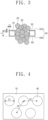
- FIG. 2 and FIG. 3 are cross-sectional views showing a porous frame-based solid electrolyte membrane according to some embodiments of the inventive concept.
- a solid electrolyte membrane 100 may include a porous frame 10, solid electrolyte particles 20, and a binder 30.
- the porous frame 10 may include a metal or a polymer material.
- the porous frame 10 may include a pore 40 penetrating the inside thereof.
- the pore 40 may be an empty space extending from an upper surface 50a of the porous frame to a lower surface 50b thereof.
- the pore 40 may be provided in plurality in the porous frame 10, the plurality of pores 40 may be disposed spaced apart from each other.
- a thickness t1 of the porous frame 10 may be 1 um to 200 um.
- the porous frame 10 may include a polymer material.
- the polymer material may include at least one of polyethylene (PE), polypropylene (PP), cellulose, polyethylene terephthalate (PET), polybutylene terephthalate (PBT), polyacrylonitrile (PAN), polystyrene (PS), polyvinyl chloride (PVC), polycarbonate (PC), polymethyl methacrylate (PMMA), nylon, polytetrafluoroethylene (PTFE), polyvinylidene fluoride (PVDF), a copolymer of vinylidene fluoride and hexafluoropropylene (PVDF-HFP), polyimide (PI), polyisoimide (PEI), a liquid crystal polymer film (LCP), polyoxymethylene (POM), polysiloxane, acrylonitrile butadiene styrene (ABS), an epoxy resin, a phenol resin, polysulfone (PSF), polyethersulf
- the porous frame 10 may include a metal material.
- the metal material may include at least one of Cu, Al, Ni, Stainless steel(SUS), Ti, Zn, or Mg.
- the porous frame 10 may be in the form of a foil made of the metal material.
- an insulation layer 90 covering both surfaces 50 of the porous frame 10 and inner surfaces of the pores 40 may be provided.
- the insulation layer 90 may reduce the occurrence of short circuit or leakage current in a battery, and may improve adhesion force of the solid electrolyte particles 20 to the porous frame 10.
- a thickness t2 of the insulation layer 90 may be 10 nm to 10 um, and may be less than the thickness t1 of the porous frame 10.
- the insulation layer 90 may include a metal oxide film.
- the metal oxide film may include at least one of a copper oxide (CuO), an aluminum oxide (Al 2 O 3 ), a nickel oxide (NiO, Ni 2 O 3 , or NiO 2 ), an iron oxide (FeO, Fe 2 O 3 , or Fe 3 O 4 ), a titanium oxide (TiO 2 ), a zinc oxide (ZnO), or a magnesium oxide(MgO).
- the solid electrolyte particles 20 may cover the both surfaces 50 of the porous frame 10, and may fill the pores 40 of the porous frame 10.
- the solid electrolyte particles 20 may include a lithium-ion conductive material.
- the lithium-ion conductive material may include at least one of a NASICON-based electrolyte(LATP, LAGP), an oxide-based electrolyte(Garnet structure LLZO, Perovskite LLTO), a sulfide-based electrolyte(LPS, LPSCl), or a polymer electrolyte (solvent-free-based and gel electrolyte).
- the binder 30 may be disposed among the solid electrolyte particles 20.
- the composition ratio of the solid electrolyte particles 20 and the binder 30 may be 20:80 to 99:1 by weight.
- the ion conductivity of the solid electrolyte membrane 100 may be decreased.
- the adhesion force of the solid electrolyte particles 20 to the porous frame 10 may decrease.
- FIG. 4 is a plan view showing a porous frame-based solid electrolyte membrane according to some embodiments of the inventive concept.
- the pore 40 may be circular.
- a diameter D1 of the pore 40 may be 0.1 um to 50,000 um, and a distance D2 from the center of the pore 40 to the center of the most adjacent pore 40 may be 0.15 um to 75,000 um.
- FIG. 5 is a flowchart for describing a method for manufacturing a porous frame-based solid electrolyte membrane according to some embodiments of the inventive concept.
- a method for manufacturing a solid electrolyte membrane may include stirring a mixture including the solid electrolyte particles 20 and the binder 30 S1, providing the mixture on the surface of the porous frame 10 S2, and compressing the porous frame 10 provided with the mixture S3.
- the porous frame 10 may include a metal or a polymer material.
- the solid electrolyte particles 20 and the binder 30 may cover both surfaces of the porous frame 10, and may fill pores 40 of the porous frame 10.
- the mixture may further include a cosolvent.
- the method for manufacturing a solid electrolyte membrane may include performing a wet process using the mixture.
- the mixture including the solid electrolyte particles 20 and the binder 30 may further include a cosolvent.
- the binder 30 may include at least one of butadiene rubber, fluorine-based rubber, nitrile butadiene rubber, hydrogenated nitrile butadiene rubber, styrene butadiene rubber, styrene butadiene styrene, styrene ethylene butadiene styrene, acrylated styrene butadiene rubber, an acrylonitrile butadiene styrene copolymer, polytetrafluoroethylene, polyvinylidene fluoride, a copolymer of vinylidene fluoride and hexafluoropropylene, polyvinyl chloride, polyacrylonitrile, polymethyl methacrylate, polyacrylate, polyethylene, polypropylene, a polyethylene oxide, polyimide, polyethylene terephthalate, polybut
- the cosolvent may include at least one of hexane, heptane, nonane, decane, benzene, toluene, xylene, anisole, cyclohexanone, methyl ethyl ketone, tetrahydrofuran, N-methylpyrrolidone, hexamethylphosphoramide, dioxane, tetramethylurea, triethylphosphate, trimethylphosphate, dimethylformamide, dimethylsulfoxide, or dimethylacetamide.
- Step S2 of providing the mixture on the surface of the porous frame 10 may include directly coating the mixture on the both surfaces 50 of the porous frame 10 and on the inner surface of the pore 40.
- the method for manufacturing a solid electrolyte membrane may further include, after Step S1 of stirring a mixture including the solid electrolyte particles 20 and the binder 30, casting the mixture and drying the cosolvent of the mixture to manufacture a solid electrolyte film.
- Step S2 of providing the mixture on the surface of the porous frame 10 may include laminating the solid electrolyte film on the both surfaces 50 of the porous frame 10 and on the inner surface of the pore 40.
- the mixture may not include a cosolvent.
- the method for manufacturing a solid electrolyte membrane may include performing a dry process using the mixture.
- the method for manufacturing a solid electrolyte membrane based on a dry process may further include, after stirring a mixture including the solid electrolyte particles 20 and the binder 30, adding an aprotic or non-polar solvent to the mixture. During the stirring, the temperature may be 25°C to 100°C.
- the binder 30 may include at least one of polytetrafluoroethylene, polyvinylidene fluoride, a copolymer of vinylidene fluoride and hexafluoropropylene, a copolymer of vinylidene fluoride and trifluoroethylene, or a terpolymer of vinylidene fluoride, trifluoroethylene and chlorotrifluoroethylene.
- the aprotic or non-polar solvent has a low boiling point, and thus, may be easily volatilized.
- the aprotic or non-polar solvent may include at least one of hexane, benzene, toluene, xylene, cyclohexanone, or methyl ethyl ketone.
- the mixture added with the aprotic or non-polar solvent may temporarily exhibit fluidity.
- the composition ratio of the mixture and the aprotic or non-polar solvent may be 1 :0.05 to 1:2 by weight.
- composition ratio of the aprotic or non-polar solvent When the composition ratio of the aprotic or non-polar solvent is higher than the above-proposed numerical value range, the fluidity of the mixture added with the aprotic or non-polar solvent is high, so that it may not be easy to control the thickness of the solid electrolyte membrane 100. When the composition ratio of the aprotic or non-polar solvent is lower than the above-proposed numerical value range, the fluidity of the mixture added with the aprotic or non-polar solvent is low, so that it may not be easy to process the mixture.
- Step S2 of providing the mixture on the surface of the porous frame 10 may include directly coating the mixture added with the aprotic or non-polar solvent on the both surfaces 50 of the porous frame 10 and on the inner surface of the pore 40.
- the method for manufacturing a solid electrolyte membrane may further include, after Step S1 of stirring a mixture including the solid electrolyte particles 20 and the binder 30, casting the mixture added with the aprotic or non-polar solvent and cooling the mixture to manufacture a solid electrolyte film.
- Step S2 of providing the mixture on the surface of the porous frame 10 may include laminating the solid electrolyte film on the both surfaces 50 of the porous frame 10 and on the inner surface of the pore 40.
- FIG. 6 is a cross-sectional view schematically showing an all-solid-state battery including a porous frame-based solid electrolyte membrane according to some embodiments of the inventive concept.
- an all-solid-state battery may include a positive electrode 110, a negative electrode 120, and a solid electrolyte membrane, and the solid electrolyte membrane may be any one of the above-described solid electrolyte membranes 100.
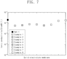
- FIG. 7 is a graph showing the room-temperature ion conductivity properties of a solid electrolyte membrane of each of Experimental Examples 1 to 8 and Comparative Example 1.
- Experimental Examples 1 to 8 and Comparative Example 1 will be described in detail.
- a solid electrolyte membrane in which LPSCl was applied as solid electrolyte particles and nitrile butadiene rubber (NBR) was applied as a binder was manufactured through a wet process.
- a porous frame was composed of nickel, and circular pores were arranged at regular intervals.
- the solid electrolyte membrane was manufactured such that the average diameter of the pore was 200 um, the interval between pores was760 um, and the porosity of the frame was 23%, and the thickness of the frame was 10 um.
- a NiO oxide layer was formed to a thickness of 25 nm on both surfaces for the purpose of insulation through surface oxidation treatment.
- a mixture was prepared in which LPSCI(Argyrodite) and NBR were dissolved in a xylene/cyclohexanone mixed cosolvent in a composition ratio of 1:1 by weight.
- the concentration of cyclohexanone in a xylene solvent is 40%.
- the mixture was coated on one surface of the porous frame and dried at room temperature, and then the mixture was coated again on the opposite side of the porous frame and dried at room temperature to manufacture a solid electrolyte membrane with both surfaces coated. Thereafter, the solid electrolyte membrane was compressed, and finally, a solid electrolyte membrane with a thickness of 25 um was manufactured.
- a blocking electrode(SUS/solid electrolyte membrane/SUS) was applied to both surfaces of the manufactured solid electrolyte membrane, and the ion conductivity of the solid electrolyte membrane was calculated through an impedance measurement at room temperature.
- the mixture was cast on a Teflon sheet, and then dried at room temperature to manufacture a solid electrolyte film.
- the same process as in Experimental Example 1 was performed except that the solid electrolyte film was applied to both surfaces of the nickel porous frame to manufacture a solid electrolyte film through lamination at 40°C.
- a solid electrolyte membrane in which LPSCl was applied as solid electrolyte particles and PTFE particles were applied as a binder in a weight ratio of 98:2 was manufactured through a wet process.
- the average diameter of the PTFE particles was 10 um.
- a mixture of LPSCl and PTFE particles were continuously stirred and melt at 40°C to form a mixture in a liquid state. Thereafter, methyl ethyl ketone (MEK) was added such that the composition ratio of the mixture and MEK (an aprotic or non-polar solvent) became 1:0.3 by weight, and a solid electrolyte membrane was manufactured through coating and room temperature drying processes as in the same manner as in Experimental Example 1.
- MEK methyl ethyl ketone
- a mixture in a liquid state whose viscosity was controlled with MEK was manufactured in the same manner as in Experimental Example 3, and a solid electrolyte membrane was prepared through a lamination process under the same conditions as in Experimental Example 2.
- LPSCI solid electrolyte particles were pressurized to 500 MPa to manufacture a solid electrolyte in a pellet form having a thickness of 400 um and a diameter of 1.2 cm.
- a blocking electrode(SUS/solid electrolyte/SUS) was applied to both surfaces of the manufactured solid electrolyte, and the ion conductivity of the solid electrolyte was calculated through an impedance measurement at room temperature.
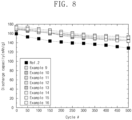
- FIG. 8 is a graph showing initial specific capacity, and specific capacity retention properties according to lifespan of a solid electrolyte membrane-based single cell of each of Experimental Examples 9 to 16 and Comparative Example 2.
- Experimental Examples 9 to 16 and Comparative Example 2 will be described in detail.
- a single cell (monocell) of an all-solid-state battery applied with a solid electrolyte membrane was manufactured.
- As a negative electrode a lithium foil with a thickness of 50 um laminated on a copper current collector was applied.
- a positive electrode active material NCM622, a solid electrolyte LPSCl, and NBR and conductive additive(Carbon black, Super-P) were mixed in a weight ratio of 80 : 10 : 5 : 5, and the mixture was dissolved in a xylene co-solvent and stirred to prepare slurry. The slurry was coated on an aluminum current collector and roll-pressed to finally manufacture a positive electrode with a thickness of 30 um.
- the solid electrolyte membrane manufactured in Experimental Example 1 was inserted between the two electrodes to manufacture a pouch cell (2 cm x 2 cm). A separate JIG was applied to maintain pressurization on both surfaces of the pouch cell.
- the pouch cell was connected to a charger/discharger, and CC-CV/CC charging/discharging was performed under the condition of 3.0 to 4.3 V cut-off and the current condition of C/5.
- a single cell to which the LPSCl solid electrolyte pellet of Comparative Example 1 was applied was manufactured.
- As a negative electrode a lithium foil with a thickness of 50 um laminated on a copper current collector was applied.
- a positive electrode active material NCM622, a solid electrolyte LPSCl, and conductive additive(Carbon black, Super-P) were mixed in a weight ratio of 70 : 25 : 5, and the mixture was pressurized to 500 MPa to manufacture a positive electrode in a pellet form with a thickness of 450 um and a diameter of 1.2 cm.
- the solid electrolyte pellet manufactured in Comparative Example 1 was inserted between the two electrodes and inserted into a pressurization JIG to form a pressurization cell.
- the pressurization cell except for its terminal was again placed in a sealed container to block contact with moisture and air.
- the pressurization cell was connected to a charger/discharger, and CC-CV/CC charging/discharging was performed under the condition of 3.0 to 4.3 V cut-off and the current condition of C/5.
- a solid electrolyte membrane has a similar thickness and mechanical strength as a typical commercially available separator. Accordingly, the solid electrolyte membrane is readily available for deformation and punching, such as bending or rolling, and it is easy to allow the solid electrolyte membrane to have a large area. In addition, when manufacturing a cell, additional pressurization conditions are relaxed, and the structure of the cell is simplified, so that cell manufacturing process costs are lowered.
- the solid electrolyte membrane itself has lithium-ion conductivity properties. Accordingly, the solid electrolyte membrane exhibits ion conductivity properties which are close to those of an electrolyte system including a separator and a liquid electrolyte.
Landscapes
- Chemical & Material Sciences (AREA)
- Chemical Kinetics & Catalysis (AREA)
- Electrochemistry (AREA)
- General Chemical & Material Sciences (AREA)
- Inorganic Chemistry (AREA)
- Manufacturing & Machinery (AREA)
- Engineering & Computer Science (AREA)
- Physics & Mathematics (AREA)
- Condensed Matter Physics & Semiconductors (AREA)
- General Physics & Mathematics (AREA)
- Dispersion Chemistry (AREA)
- Conductive Materials (AREA)
- Cell Separators (AREA)
- Secondary Cells (AREA)
Abstract
Description
- This U.S. non-provisional patent application claims priority under 35 U.S.C. § 119 of
Korean Patent Application No. 10-2021-0022855, filed on February 19, 2021 10-2021-0060500, filed on May 11, 2021 - The present disclosure herein relates to a porous frame-based solid electrolyte membrane and a manufacturing method thereof, and an all-solid-state battery including the porous frame-based solid electrolyte membrane.
- Lithium-ion batteries are energy storage devices with high energy density and stable output properties, and are variously applied to mobile IT to electric vehicles (EVs) and energy storage systems (ESS). However, lithium-ion batteries use organic electrolytes with a high risk of ignition and operate in a high voltage range, fire accidents may occur due to unexpected behavior. In addition, in recent years, the industry of secondary batteries is rapidly shifted from small secondary batteries such as power sources for portable devices to medium to large secondary batteries such as electric vehicles and energy storage systems, so that the stability problem is becoming more of a serious issue.
- In order to secure the stability of lithium-ion batteries, various methods are being applied. Among them, the development of a solid electrolyte has become the biggest issue in recent years. When a ceramic-based solid electrolyte having a separator function is used, the structure of a battery is simplified, there is no risk of leakage, ignition, and explosion of the electrolyte, and the use of a high-voltage electrode is not limited due to excellent electrochemical stability of the electrolyte. In addition, since a lithium metal having a theoretical capacity of 10 times or more than that of a graphite material commercially available as a typical negative electrode material may be used, the electrolyte may be extended to an electrolyte for a lithium-air battery or a lithium-sulfur battery, and thus, may dramatically improve energy density for mass and volume.
- The present disclosure provides a thin-film solid electrolyte membrane and a manufacturing method thereof, and an all-solid-state battery including the thin-film solid electrolyte membrane.
- An embodiment of the inventive concept provides a solid electrolyte membrane including a porous frame including a metal or a polymer material, solid electrolyte particles covering both surfaces of the porous frame, and filling pores of the porous frame, and a binder between the solid electrolyte particles.
- In an embodiment of the inventive concept, a method for manufacturing a solid electrolyte membrane includes stirring a mixture including solid electrolyte particles and a binder, providing the mixture on the surface of a porous frame, and compressing the porous frame provided with the mixture, wherein the porous frame includes a metal or a polymer material, and the solid electrolyte particles and the binder cover both surfaces of the porous frame and fill pores of the porous frame.
- In an embodiment of the inventive concept, an all-solid-state battery includes a positive electrode, a negative electrode, and a solid electrolyte, wherein the solid electrolyte may be the solid electrolyte membrane.
- The accompanying drawings are included to provide a further understanding of the inventive concept, and are incorporated in and constitute a part of this specification. The drawings illustrate exemplary embodiments of the inventive concept and, together with the description, serve to explain principles of the inventive concept. In the drawings:
-
FIG. 1 is a schematic perspective view showing a porous frame-based solid electrolyte membrane according to some embodiments of the inventive concept; -
FIG. 2 andFIG. 3 are cross-sectional views showing a porous frame-based solid electrolyte membrane according to some embodiments of the inventive concept; -
FIG. 4 is a plan view showing a porous frame-based solid electrolyte membrane according to some embodiments of the inventive concept; -
FIG. 5 is a flowchart for describing a method for manufacturing a porous frame-based solid electrolyte membrane according to some embodiments of the inventive concept; -
FIG. 6 is a cross-sectional view schematically showing an all-solid-state battery including a porous frame-based solid electrolyte membrane according to some embodiments of the inventive concept; -
FIG. 7 is a graph showing the room-temperature ion conductivity properties of a solid electrolyte membrane of each of Experimental Examples 1 to 8 and Comparative Example 1; and -
FIG. 8 is a graph showing initial specific capacity, and specific capacity retention properties according to lifespan of a solid electrolyte membrane-based single cell of each of Experimental Examples 9 to 16 and Comparative Example 2. - In order to facilitate sufficient understanding of the configuration and effects of the inventive concept, preferred embodiments of the inventive concept will be described with reference to the accompanying drawings. However, the inventive concept is not limited to the embodiments set forth below, and may be embodied in various forms and modified in many alternate forms. Rather, these embodiments are provided so that this disclosure will be thorough and complete, and will fully convey the scope of the inventive concept to those skilled in the art to which the inventive concept pertains. In the accompanying drawings, elements are illustrated enlarged from the actual size thereof for convenience of description, and the ratio of each element may be exaggerated or reduced.
-
FIG. 1 is a schematic perspective view showing a porous frame-based solid electrolyte membrane according to some embodiments of the inventive concept.FIG. 2 andFIG. 3 are cross-sectional views showing a porous frame-based solid electrolyte membrane according to some embodiments of the inventive concept. - Referring to
FIG. 1 to FIG. 3 , asolid electrolyte membrane 100 may include aporous frame 10,solid electrolyte particles 20, and abinder 30. - The
porous frame 10 may include a metal or a polymer material. Theporous frame 10 may include apore 40 penetrating the inside thereof. Thepore 40 may be an empty space extending from anupper surface 50a of the porous frame to alower surface 50b thereof. Thepore 40 may be provided in plurality in theporous frame 10, the plurality ofpores 40 may be disposed spaced apart from each other. A thickness t1 of theporous frame 10 may be 1 um to 200 um. - The
porous frame 10 may include a polymer material. As an example, the polymer material may include at least one of polyethylene (PE), polypropylene (PP), cellulose, polyethylene terephthalate (PET), polybutylene terephthalate (PBT), polyacrylonitrile (PAN), polystyrene (PS), polyvinyl chloride (PVC), polycarbonate (PC), polymethyl methacrylate (PMMA), nylon, polytetrafluoroethylene (PTFE), polyvinylidene fluoride (PVDF), a copolymer of vinylidene fluoride and hexafluoropropylene (PVDF-HFP), polyimide (PI), polyisoimide (PEI), a liquid crystal polymer film (LCP), polyoxymethylene (POM), polysiloxane, acrylonitrile butadiene styrene (ABS), an epoxy resin, a phenol resin, polysulfone (PSF), polyethersulfone (PES), or polyetheretherketone (PEEK). When theporous frame 10 includes a polymer material, theporous frame 10 may be in the form of a film made of the polymer material. - The
porous frame 10 may include a metal material. As an example, the metal material may include at least one of Cu, Al, Ni, Stainless steel(SUS), Ti, Zn, or Mg. Theporous frame 10 may be in the form of a foil made of the metal material. - When the
porous frame 10 includes a metal material, aninsulation layer 90 covering bothsurfaces 50 of theporous frame 10 and inner surfaces of thepores 40 may be provided. Theinsulation layer 90 may reduce the occurrence of short circuit or leakage current in a battery, and may improve adhesion force of thesolid electrolyte particles 20 to theporous frame 10. A thickness t2 of theinsulation layer 90 may be 10 nm to 10 um, and may be less than the thickness t1 of theporous frame 10. - The
insulation layer 90 may include a metal oxide film. As an example, the metal oxide film may include at least one of a copper oxide (CuO), an aluminum oxide (Al2O3), a nickel oxide (NiO, Ni2O3, or NiO2), an iron oxide (FeO, Fe2O3, or Fe3O4), a titanium oxide (TiO2), a zinc oxide (ZnO), or a magnesium oxide(MgO). - The
solid electrolyte particles 20 may cover the bothsurfaces 50 of theporous frame 10, and may fill thepores 40 of theporous frame 10. Thesolid electrolyte particles 20 may include a lithium-ion conductive material. As an example, the lithium-ion conductive material may include at least one of a NASICON-based electrolyte(LATP, LAGP), an oxide-based electrolyte(Garnet structure LLZO, Perovskite LLTO), a sulfide-based electrolyte(LPS, LPSCl), or a polymer electrolyte (solvent-free-based and gel electrolyte). - The
binder 30 may be disposed among thesolid electrolyte particles 20. The composition ratio of thesolid electrolyte particles 20 and thebinder 30 may be 20:80 to 99:1 by weight. When the composition ratio of thebinder 30 is higher than the above-proposed numerical value range, the ion conductivity of thesolid electrolyte membrane 100 may be decreased. When the composition ratio of thebinder 30 is lower than the above-proposed numerical value range, the adhesion force of thesolid electrolyte particles 20 to theporous frame 10 may decrease. -
FIG. 4 is a plan view showing a porous frame-based solid electrolyte membrane according to some embodiments of the inventive concept. - Referring to
FIG. 4 , thepore 40 may be circular. When thepore 40 is circular, a diameter D1 of thepore 40 may be 0.1 um to 50,000 um, and a distance D2 from the center of thepore 40 to the center of the mostadjacent pore 40 may be 0.15 um to 75,000 um. - Hereinafter, a method for manufacturing a porous frame-based solid electrolyte membrane according to the inventive concept will be described.
-
FIG. 5 is a flowchart for describing a method for manufacturing a porous frame-based solid electrolyte membrane according to some embodiments of the inventive concept. - Referring to
FIG. 1 andFIG. 5 , a method for manufacturing a solid electrolyte membrane according to an embodiment of the inventive concept may include stirring a mixture including thesolid electrolyte particles 20 and thebinder 30 S1, providing the mixture on the surface of theporous frame 10 S2, and compressing theporous frame 10 provided with the mixture S3. Theporous frame 10 may include a metal or a polymer material. Thesolid electrolyte particles 20 and thebinder 30 may cover both surfaces of theporous frame 10, and may fillpores 40 of theporous frame 10. - According to some embodiments, the mixture may further include a cosolvent. In this case, the method for manufacturing a solid electrolyte membrane may include performing a wet process using the mixture.
- Hereinafter, a method for manufacturing a solid electrolyte membrane based on a wet process will be described in more detail.
- The mixture including the
solid electrolyte particles 20 and thebinder 30 may further include a cosolvent. As an example, thebinder 30 may include at least one of butadiene rubber, fluorine-based rubber, nitrile butadiene rubber, hydrogenated nitrile butadiene rubber, styrene butadiene rubber, styrene butadiene styrene, styrene ethylene butadiene styrene, acrylated styrene butadiene rubber, an acrylonitrile butadiene styrene copolymer, polytetrafluoroethylene, polyvinylidene fluoride, a copolymer of vinylidene fluoride and hexafluoropropylene, polyvinyl chloride, polyacrylonitrile, polymethyl methacrylate, polyacrylate, polyethylene, polypropylene, a polyethylene oxide, polyimide, polyethylene terephthalate, polybutylene terephthalate, polyphenyl sulfide, polyetheretherketone, or tetrafluoroethylene. As an example, the cosolvent may include at least one of hexane, heptane, nonane, decane, benzene, toluene, xylene, anisole, cyclohexanone, methyl ethyl ketone, tetrahydrofuran, N-methylpyrrolidone, hexamethylphosphoramide, dioxane, tetramethylurea, triethylphosphate, trimethylphosphate, dimethylformamide, dimethylsulfoxide, or dimethylacetamide. - Hereinafter, as an example of the method for manufacturing a solid electrolyte membrane based on a wet process, Step S2 of providing the mixture on the surface of the
porous frame 10 may include directly coating the mixture on the bothsurfaces 50 of theporous frame 10 and on the inner surface of thepore 40. - Hereinafter, as another example of the method for manufacturing a solid electrolyte membrane based on a wet process, the method for manufacturing a solid electrolyte membrane may further include, after Step S1 of stirring a mixture including the
solid electrolyte particles 20 and thebinder 30, casting the mixture and drying the cosolvent of the mixture to manufacture a solid electrolyte film. In this case, Step S2 of providing the mixture on the surface of theporous frame 10 may include laminating the solid electrolyte film on the bothsurfaces 50 of theporous frame 10 and on the inner surface of thepore 40. - According to other embodiments, the mixture may not include a cosolvent. In this case, the method for manufacturing a solid electrolyte membrane may include performing a dry process using the mixture.
- Hereinafter, a method for manufacturing a solid electrolyte membrane based on a dry process will be described in more detail.
- The method for manufacturing a solid electrolyte membrane based on a dry process may further include, after stirring a mixture including the
solid electrolyte particles 20 and thebinder 30, adding an aprotic or non-polar solvent to the mixture. During the stirring, the temperature may be 25°C to 100°C. - As an example, the
binder 30 may include at least one of polytetrafluoroethylene, polyvinylidene fluoride, a copolymer of vinylidene fluoride and hexafluoropropylene, a copolymer of vinylidene fluoride and trifluoroethylene, or a terpolymer of vinylidene fluoride, trifluoroethylene and chlorotrifluoroethylene. - The aprotic or non-polar solvent has a low boiling point, and thus, may be easily volatilized. As an example, the aprotic or non-polar solvent may include at least one of hexane, benzene, toluene, xylene, cyclohexanone, or methyl ethyl ketone. The mixture added with the aprotic or non-polar solvent may temporarily exhibit fluidity. The composition ratio of the mixture and the aprotic or non-polar solvent may be 1 :0.05 to 1:2 by weight. When the composition ratio of the aprotic or non-polar solvent is higher than the above-proposed numerical value range, the fluidity of the mixture added with the aprotic or non-polar solvent is high, so that it may not be easy to control the thickness of the
solid electrolyte membrane 100. When the composition ratio of the aprotic or non-polar solvent is lower than the above-proposed numerical value range, the fluidity of the mixture added with the aprotic or non-polar solvent is low, so that it may not be easy to process the mixture. - Hereinafter, as an example of the method for manufacturing a solid electrolyte membrane based on a dry process, Step S2 of providing the mixture on the surface of the
porous frame 10 may include directly coating the mixture added with the aprotic or non-polar solvent on the bothsurfaces 50 of theporous frame 10 and on the inner surface of thepore 40. - Hereinafter, as another example of the method for manufacturing a solid electrolyte membrane based on a dry process, the method for manufacturing a solid electrolyte membrane may further include, after Step S1 of stirring a mixture including the
solid electrolyte particles 20 and thebinder 30, casting the mixture added with the aprotic or non-polar solvent and cooling the mixture to manufacture a solid electrolyte film. Step S2 of providing the mixture on the surface of theporous frame 10 may include laminating the solid electrolyte film on the bothsurfaces 50 of theporous frame 10 and on the inner surface of thepore 40. -
FIG. 6 is a cross-sectional view schematically showing an all-solid-state battery including a porous frame-based solid electrolyte membrane according to some embodiments of the inventive concept. - Referring to
FIG. 6 , an all-solid-state battery may include apositive electrode 110, anegative electrode 120, and a solid electrolyte membrane, and the solid electrolyte membrane may be any one of the above-describedsolid electrolyte membranes 100. -
FIG. 7 is a graph showing the room-temperature ion conductivity properties of a solid electrolyte membrane of each of Experimental Examples 1 to 8 and Comparative Example 1. Hereinafter, Experimental Examples 1 to 8 and Comparative Example 1 will be described in detail. - A solid electrolyte membrane in which LPSCl was applied as solid electrolyte particles and nitrile butadiene rubber (NBR) was applied as a binder was manufactured through a wet process. A porous frame was composed of nickel, and circular pores were arranged at regular intervals. The solid electrolyte membrane was manufactured such that the average diameter of the pore was 200 um, the interval between pores was760 um, and the porosity of the frame was 23%, and the thickness of the frame was 10 um. A NiO oxide layer was formed to a thickness of 25 nm on both surfaces for the purpose of insulation through surface oxidation treatment. A mixture was prepared in which LPSCI(Argyrodite) and NBR were dissolved in a xylene/cyclohexanone mixed cosolvent in a composition ratio of 1:1 by weight. The concentration of cyclohexanone in a xylene solvent is 40%. The mixture was coated on one surface of the porous frame and dried at room temperature, and then the mixture was coated again on the opposite side of the porous frame and dried at room temperature to manufacture a solid electrolyte membrane with both surfaces coated. Thereafter, the solid electrolyte membrane was compressed, and finally, a solid electrolyte membrane with a thickness of 25 um was manufactured. A blocking electrode(SUS/solid electrolyte membrane/SUS) was applied to both surfaces of the manufactured solid electrolyte membrane, and the ion conductivity of the solid electrolyte membrane was calculated through an impedance measurement at room temperature.
- Unlike Experimental Example 1, the mixture was cast on a Teflon sheet, and then dried at room temperature to manufacture a solid electrolyte film. The same process as in Experimental Example 1 was performed except that the solid electrolyte film was applied to both surfaces of the nickel porous frame to manufacture a solid electrolyte film through lamination at 40°C.
- A solid electrolyte membrane in which LPSCl was applied as solid electrolyte particles and PTFE particles were applied as a binder in a weight ratio of 98:2 was manufactured through a wet process. The average diameter of the PTFE particles was 10 um. A mixture of LPSCl and PTFE particles were continuously stirred and melt at 40°C to form a mixture in a liquid state. Thereafter, methyl ethyl ketone (MEK) was added such that the composition ratio of the mixture and MEK (an aprotic or non-polar solvent) became 1:0.3 by weight, and a solid electrolyte membrane was manufactured through coating and room temperature drying processes as in the same manner as in Experimental Example 1.
- A mixture in a liquid state whose viscosity was controlled with MEK was manufactured in the same manner as in Experimental Example 3, and a solid electrolyte membrane was prepared through a lamination process under the same conditions as in Experimental Example 2.
- The same process as in Experimental Example 1 was performed except that LPSCl and NBR were applied in a composition ratio of 99:1 by weight.
- The same process as in Experimental Example 2 was performed except that LPSCl and NBR were applied in a composition ratio of 99:1 by weight.
- The same process as in Experimental Example 3 was performed except that LPSCl and PTFE were applied in a composition ratio of 99:1 by weight.
- The same process as in Experimental Example 4 was performed except that LPSCl and PTFE were applied in a composition ratio of 99:1 by weight.
- LPSCI solid electrolyte particles were pressurized to 500 MPa to manufacture a solid electrolyte in a pellet form having a thickness of 400 um and a diameter of 1.2 cm. A blocking electrode(SUS/solid electrolyte/SUS) was applied to both surfaces of the manufactured solid electrolyte, and the ion conductivity of the solid electrolyte was calculated through an impedance measurement at room temperature.
- Referring to
FIG. 7 , it is observed that the ion conductivity of each of Experimental Examples 1 to 8, which are solid electrolytes in a membrane form, was close to the ion conductivity of Comparative Example 1, which is a typical solid electrolyte in a pellet form. This may be because lithium ions only moved within a porous structure, and thus, loss of ion conductivity was minimized due to a simple and short movement path. Therefore, compared to Comparative Example 1, the solid electrolytes in a membrane form of each of Experimental Examples 1 to 8 are advantageous for being thinner and larger due to the high tensile strength of the porous frame, while maintaining a similar level of ion conductivity. -
FIG. 8 is a graph showing initial specific capacity, and specific capacity retention properties according to lifespan of a solid electrolyte membrane-based single cell of each of Experimental Examples 9 to 16 and Comparative Example 2. Hereinafter, Experimental Examples 9 to 16 and Comparative Example 2 will be described in detail. - A single cell (monocell) of an all-solid-state battery applied with a solid electrolyte membrane was manufactured. As a negative electrode, a lithium foil with a thickness of 50 um laminated on a copper current collector was applied. A positive electrode active material NCM622, a solid electrolyte LPSCl, and NBR and conductive additive(Carbon black, Super-P) were mixed in a weight ratio of 80 : 10 : 5 : 5, and the mixture was dissolved in a xylene co-solvent and stirred to prepare slurry. The slurry was coated on an aluminum current collector and roll-pressed to finally manufacture a positive electrode with a thickness of 30 um. The solid electrolyte membrane manufactured in Experimental Example 1 was inserted between the two electrodes to manufacture a pouch cell (2 cm x 2 cm). A separate JIG was applied to maintain pressurization on both surfaces of the pouch cell. The pouch cell was connected to a charger/discharger, and CC-CV/CC charging/discharging was performed under the condition of 3.0 to 4.3 V cut-off and the current condition of C/5.
- The same process as in Experimental Example 9 was performed except that the solid electrolyte membrane of Experimental Example 2 was applied.
- The same process as in Experimental Example 9 was performed except that the solid electrolyte membrane of Experimental Example 3 was applied.
- The same process as in Experimental Example 9 was performed except that the solid electrolyte membrane of Experimental Example 4 was applied.
- The same process as in Experimental Example 9 was performed except that the solid electrolyte membrane of Experimental Example 5 was applied.
- The same process as in Experimental Example 9 was performed except that the solid electrolyte membrane of Experimental Example 6 was applied.
- The same process as in Experimental Example 9 was performed except that the solid electrolyte membrane of Experimental Example 7 was applied.
- The same process as in Experimental Example 9 was performed except that the solid electrolyte membrane of Experimental Example 8 was applied.
- A single cell to which the LPSCl solid electrolyte pellet of Comparative Example 1 was applied was manufactured. As a negative electrode, a lithium foil with a thickness of 50 um laminated on a copper current collector was applied. A positive electrode active material NCM622, a solid electrolyte LPSCl, and conductive additive(Carbon black, Super-P) were mixed in a weight ratio of 70 : 25 : 5, and the mixture was pressurized to 500 MPa to manufacture a positive electrode in a pellet form with a thickness of 450 um and a diameter of 1.2 cm. The solid electrolyte pellet manufactured in Comparative Example 1 was inserted between the two electrodes and inserted into a pressurization JIG to form a pressurization cell. The pressurization cell except for its terminal was again placed in a sealed container to block contact with moisture and air. The pressurization cell was connected to a charger/discharger, and CC-CV/CC charging/discharging was performed under the condition of 3.0 to 4.3 V cut-off and the current condition of C/5.
- Referring to
FIG. 8 , it is observed that the single cell of each of Experimental Examples 9 to 16 to which the solid electrolyte membrane was applied had excellent initial specific capacity compared to the initial specific capacity of the single cell of Comparative Example 2 to which a typical solid electrolyte membrane in a pellet form was applied. In addition, it was observed that even when the charging/discharging was repeated for 500 times, the specific capacity of the single cell of each of Experimental Examples 9 to 16 was larger than the specific capacity of the single cell of Comparative Example 2, so that it can be confirmed that Experimental Examples 9 to 16 had excellent specific capacity retention properties according to lifespan compared to that of Comparative Example 2. - According to the inventive concept, a solid electrolyte membrane has a similar thickness and mechanical strength as a typical commercially available separator. Accordingly, the solid electrolyte membrane is readily available for deformation and punching, such as bending or rolling, and it is easy to allow the solid electrolyte membrane to have a large area. In addition, when manufacturing a cell, additional pressurization conditions are relaxed, and the structure of the cell is simplified, so that cell manufacturing process costs are lowered.
- According to the inventive concept, unlike a typical commercially available separator, the solid electrolyte membrane itself has lithium-ion conductivity properties. Accordingly, the solid electrolyte membrane exhibits ion conductivity properties which are close to those of an electrolyte system including a separator and a liquid electrolyte.
- The effects to be obtained by the present invention are not limited to the effects mentioned above, and other effects not mentioned will be clearly understood by those skilled in the art from the above description.
- Embodiments of the present invention have been described with reference to the accompanying drawings. However, the present invention may be implemented in other detailed forms without changing the technical spirit or necessary features thereof. It is therefore to be understood that the above-described embodiments are illustrative in all aspects and not restrictive.
Claims (17)
- A solid electrolyte membrane comprising:a porous frame including a metal or a polymer material;solid electrolyte particles covering both surfaces of the porous frame, and filling pores of the porous frame; anda binder between the solid electrolyte particles.
- The solid electrolyte membrane of claim 1, wherein the thickness of the porous frame is 1 um to 200 um.
- The solid electrolyte membrane of claim 1, wherein the porous frame comprises a metal, and the solid electrolyte membrane further comprises an insulation layer covering the both surfaces of the porous frame and inner surfaces of the pores.
- The solid electrolyte membrane of claim 3, wherein the thickness of the insulation layer is less than the thickness of the porous frame.
- The solid electrolyte membrane of claim 4, wherein the thickness of the insulation layers is 10 nm to 10 um.
- The solid electrolyte membrane of claim 3, wherein the insulation layer comprises a metal oxide film.
- The solid electrolyte membrane of claim 1, wherein the composition ratio of the solid electrolyte particles and the binder is 20:80 to 99:1 by weight.
- The solid electrolyte membrane of claim 1, wherein the pore is circular, the diameter of the pore is 0.1 um to 50,000 um, and the distance from the center of the pore to the center of the most adjacent pore is 0.15 um to 75,000 um.
- A method for manufacturing a solid electrolyte membrane, the method comprising:stirring a mixture including solid electrolyte particles and a binder;providing the mixture on the surface of a porous frame; andcompressing the porous frame provided with the mixture,wherein:the porous frame includes a metal or a polymer material; andthe solid electrolyte particles and the binder cover both surfaces of the porous frame and fill pores of the porous frame.
- The method of claim 9, wherein the mixture further comprises a cosolvent, wherein the cosolvent includes at least one of hexane, heptane, nonane, decane, benzene, toluene, xylene, anisole, cyclohexanone, methyl ethyl ketone, tetrahydrofuran, N-methylpyrrolidone, hexamethylphosphoramide, dioxane, tetramethylurea, triethylphosphate, trimethylphosphate, dimethylformamide, dimethylsulfoxide, or dimethylacetamide.
- The method of claim 10, wherein the providing of the mixture on the surface of the porous frame comprises directly coating the mixture on the both surfaces of the porous frame and inner surfaces of the pores.
- The method of claim 10, further comprising:casting the mixture; anddrying the cosolvent of the mixture to manufacture a solid electrolyte film,wherein the providing of the mixture on the surface of the porous frame comprises laminating the solid electrolyte film on the both surfaces of the porous frame and the inner surfaces of the pores.
- The method of claim 9, further comprising, after stirring the mixture including solid electrolyte particles and a binder, adding an aprotic or non-polar solvent to the mixture, wherein the aprotic or non-polar solvent includes at least one of hexane, benzene, toluene, xylene, cyclohexanone, or methyl ethyl ketone.
- The method of claim 13, wherein the composition ratio of the mixture and the aprotic or non-polar solvent is 1:0.05 to 1:2 by weight.
- The method of claim 14, wherein the providing of the mixture on the surface of the porous frame comprises directly coating the mixture added with the aprotic or non-polar solvent on the both surfaces of the porous frame and the inner surfaces of the pores.
- The method of claim 14, further comprising:casting the mixture added with the aprotic or non-polar solvent; andcooling the mixture to manufacture a solid electrolyte film,wherein the providing of the mixture on the surface of the porous frame comprises laminating the solid electrolyte film on the both surfaces of the porous frame and the inner surfaces of the pores.
- An all-solid-state battery comprising:a positive electrode;a negative electrode; anda solid electrolyte, wherein the solid electrolyte is a solid electrolyte membrane according to any one of claims 1 to 8.
Applications Claiming Priority (3)
| Application Number | Priority Date | Filing Date | Title |
|---|---|---|---|
| KR20210022855 | 2021-02-19 | ||
| KR1020210060500A KR20220119305A (en) | 2021-02-19 | 2021-05-11 | Porous frame-based solid electrolyte membrane and its manufacturing method and all-solid-state battery including the same |
| PCT/KR2022/002421 WO2022177346A1 (en) | 2021-02-19 | 2022-02-18 | Porous frame-based solid electrolyte membrane, method for manufacturing same, and all-solid-state battery comprising same |
Publications (2)
| Publication Number | Publication Date |
|---|---|
| EP4297141A1 true EP4297141A1 (en) | 2023-12-27 |
| EP4297141A4 EP4297141A4 (en) | 2025-01-29 |
Family
ID=82901060
Family Applications (1)
| Application Number | Title | Priority Date | Filing Date |
|---|---|---|---|
| EP22756544.7A Pending EP4297141A4 (en) | 2021-02-19 | 2022-02-18 | Porous frame-based solid electrolyte membrane, method for manufacturing same, and all-solid-state battery comprising same |
Country Status (4)
| Country | Link |
|---|---|
| US (1) | US12531313B2 (en) |
| EP (1) | EP4297141A4 (en) |
| JP (1) | JP2024507026A (en) |
| WO (1) | WO2022177346A1 (en) |
Families Citing this family (2)
| Publication number | Priority date | Publication date | Assignee | Title |
|---|---|---|---|---|
| WO2025068387A1 (en) * | 2023-09-26 | 2025-04-03 | W. L. Gore & Associates, Inc. | Electrochemical cell and vent assembly |
| KR20250147982A (en) | 2024-04-03 | 2025-10-14 | 주식회사 엘지에너지솔루션 | All solid state battery with excellent process efficiency and the manufactruing method of the all solid state battery |
Family Cites Families (29)
| Publication number | Priority date | Publication date | Assignee | Title |
|---|---|---|---|---|
| JP3937675B2 (en) * | 2000-02-24 | 2007-06-27 | 凸版印刷株式会社 | Method for forming hydrophilic polymer membrane |
| KR100352562B1 (en) | 2000-03-27 | 2002-09-12 | 한국과학기술연구원 | Fabrication of Membrane-Electrode Assembly for Fuel Cells |
| ES3010715T3 (en) * | 2004-07-07 | 2025-04-04 | Lg Energy Solution Ltd | New organic/inorganic composite porous film and electrochemical device prepared thereby |
| US20080118848A1 (en) * | 2006-11-16 | 2008-05-22 | Electronics & Telecommunications Research Institute | Aqeuous electrolyte composition and sealed-type primary film battery including electrolyte layer formed of the aqueous electrolyte composition |
| KR20120089413A (en) | 2010-12-07 | 2012-08-10 | 삼성전자주식회사 | Proton conducting solid oxide electrolyte membrane, membrane electrode assembly and fuel cell comprising the membrane, and method for preparing the electrolyte membrane |
| EP2732487A4 (en) * | 2011-07-11 | 2015-04-08 | California Inst Of Techn | NEW SEPARATORS FOR ELECTROCHEMICAL SYSTEMS |
| CN103781832B (en) * | 2011-09-09 | 2015-08-19 | 旭化成纤维株式会社 | polyketone porous membrane |
| KR101987008B1 (en) | 2012-06-15 | 2019-06-12 | 한국전자통신연구원 | Solid polymer electrolytes, methods for manufacturing the same, and lithum cell including thereof |
| JP5785574B2 (en) * | 2013-02-22 | 2015-09-30 | 出光興産株式会社 | Solid electrolyte sheet for lithium battery, method for producing the same, and all-solid secondary battery using the same |
| KR20140131441A (en) * | 2013-05-03 | 2014-11-13 | 한국생산기술연구원 | Method for manufacturing solid electrolyte for solid oxide fuel cell and manufacturing method for unit cell of the solid oxide fuel cell |
| US10333173B2 (en) | 2014-11-14 | 2019-06-25 | Medtronic, Inc. | Composite separator and electrolyte for solid state batteries |
| JP6943359B2 (en) * | 2014-12-19 | 2021-09-29 | 三星電子株式会社Samsung Electronics Co.,Ltd. | Composite film, its manufacturing method, negative electrode structure including it, and lithium secondary battery |
| KR101684074B1 (en) | 2015-03-12 | 2016-12-07 | 현대자동차주식회사 | A manufacturing method of all-solid battery using wet-dry process |
| JP7273513B2 (en) * | 2015-11-30 | 2023-05-15 | ユニバーシティ オブ メリーランド, カレッジ パーク | Solid state Li-S battery and method of making same |
| KR102438137B1 (en) * | 2015-12-02 | 2022-08-30 | 에스케이이노베이션 주식회사 | Separator for secondary cell havign excelletn heat resistance and shut down property |
| WO2018092484A1 (en) * | 2016-11-15 | 2018-05-24 | 株式会社村田製作所 | Lithium ion conductor, all solid battery, electronic device, electronic card, wearable device and electric vehicle |
| KR102193945B1 (en) | 2016-11-22 | 2020-12-22 | 한국전기연구원 | Method of manufacturing a solid electrolyte layer and electrode composite layer containing a sulfide-based solid electrolyte |
| KR102398467B1 (en) | 2017-04-12 | 2022-05-13 | 한국전기연구원 | A method for producing a sulfide-based solid electrolyte powder, a method for producing an electrode composite layer and a solid electrolyte layer including a solid electrolyte powder, and solid state battery including the same |
| KR101953738B1 (en) | 2017-10-11 | 2019-03-04 | 한국에너지기술연구원 | Composite Electrode with Ionic Liquid for All-Solid-State Battery, Method Of Manufacturing The Same, And All-Solid-State Lithium Battery Comprising The Same |
| JP7045642B2 (en) * | 2018-04-27 | 2022-04-01 | トヨタ自動車株式会社 | All solid state battery |
| CN108878751B (en) | 2018-07-03 | 2021-07-30 | 宁德卓高新材料科技有限公司 | Conductive ceramic composite diaphragm and solid-state battery |
| CN109494390A (en) | 2018-10-30 | 2019-03-19 | 溧阳天目先导电池材料科技有限公司 | A kind of modified solid electrolyte membrane and preparation method thereof and lithium battery |
| EP3787092A4 (en) | 2018-12-06 | 2021-09-01 | Lg Chem, Ltd. | SOLID ELECTROLYTIC MEMBRANE, ITS MANUFACTURING PROCESS AND FULLY SOLID BATTERY INCLUDING IT |
| KR102446619B1 (en) | 2019-03-19 | 2022-09-22 | 주식회사 엘지에너지솔루션 | A electrolyte membrane for all solid-state battery and a method for manufacturing the same |
| KR102751122B1 (en) | 2019-05-09 | 2025-01-06 | 주식회사 엘지에너지솔루션 | A method for manufacturing an all solid state lithium secondary battery |
| WO2020252427A1 (en) | 2019-06-13 | 2020-12-17 | Ampcera Inc. | A solid-state electrolyte membrane |
| CN112448023B (en) * | 2019-08-28 | 2022-02-18 | 宁德时代新能源科技股份有限公司 | Solid electrolyte membrane and solid lithium metal battery |
| US20240243325A1 (en) * | 2020-08-07 | 2024-07-18 | Mitsui Mining & Smelting Co., Ltd. | Solid electrolyte assembly and electrochemical element comprising same |
| CN112201851B (en) | 2020-10-22 | 2021-08-10 | 江苏厚生新能源科技有限公司 | Solid electrolyte slurry, preparation method thereof, diaphragm and lithium battery |
-
2021
- 2021-11-12 US US17/525,858 patent/US12531313B2/en active Active
-
2022
- 2022-02-18 WO PCT/KR2022/002421 patent/WO2022177346A1/en not_active Ceased
- 2022-02-18 JP JP2023516735A patent/JP2024507026A/en active Pending
- 2022-02-18 EP EP22756544.7A patent/EP4297141A4/en active Pending
Also Published As
| Publication number | Publication date |
|---|---|
| WO2022177346A1 (en) | 2022-08-25 |
| US12531313B2 (en) | 2026-01-20 |
| EP4297141A4 (en) | 2025-01-29 |
| US20220271393A1 (en) | 2022-08-25 |
| JP2024507026A (en) | 2024-02-16 |
Similar Documents
| Publication | Publication Date | Title |
|---|---|---|
| EP3043402B1 (en) | Protective film, separator using same, and secondary battery | |
| KR102166391B1 (en) | Secondary zinc-manganese dioxide batteries for high power applications | |
| KR101734328B1 (en) | Electrode assembly, Method of manufacturing the same and Electrochemical device comprising the electrode assembly | |
| EP0842547A1 (en) | Low resistance rechargeable lithium-ion battery | |
| KR20140111622A (en) | Method for predoping lithium, method of preparing lithium secondary battery comprising the same, and lithium secondary battery obtained therefrom | |
| WO2021046151A1 (en) | Aqueous electrochemical cells using polymer gel electrolytes | |
| US20150162571A1 (en) | Concave cell design for an alkaline battery with a comb spacer | |
| US12463245B2 (en) | High voltage electrolyte for 5V solid state lithium-ion battery cell | |
| US12531313B2 (en) | Porous frame-based solid electrolyte membrane and manufacturing method thereof, and all-solid-state battery including the same | |
| US10559857B2 (en) | Separator comprising force-locked particles | |
| WO2013047379A1 (en) | Lithium secondary battery and method for producing same | |
| KR101625204B1 (en) | Method for preparing electrode assembly, electrode assembly therefrom, and electrochemical device comprising the same | |
| CN116636028A (en) | Hierarchical composition electrode with mixture of active components and solid electrolyte | |
| KR20220119305A (en) | Porous frame-based solid electrolyte membrane and its manufacturing method and all-solid-state battery including the same | |
| JP2000113876A (en) | Electrode for electrochemical device, manufacture of the same, and electrochemical device | |
| CN116745958A (en) | Solid electrolyte membrane based on porous framework, manufacturing method thereof, and all-solid-state battery including same | |
| KR20160024685A (en) | Lithium secondary battery having side bead | |
| KR102690251B1 (en) | Method for preparing electrochemical devices | |
| KR20220057166A (en) | Bipolar all-solid-state battery comprising a porous supporting layer | |
| US20240347735A1 (en) | Electrodes, electrochemical cells, and methods for making electrodes | |
| US20150162570A1 (en) | Beveled cell design for an alkaline battery to remove gas | |
| CN120749220A (en) | In-situ polymerization solid electrolyte and preparation method thereof | |
| JP2021150155A (en) | Lithium-ion battery | |
| HK1226869A1 (en) | Protective film, separator using same, and secondary battery | |
| WO2015089205A1 (en) | Beveled cell design for an alkaline battery to remove gas |
Legal Events
| Date | Code | Title | Description |
|---|---|---|---|
| STAA | Information on the status of an ep patent application or granted ep patent |
Free format text: STATUS: THE INTERNATIONAL PUBLICATION HAS BEEN MADE |
|
| PUAI | Public reference made under article 153(3) epc to a published international application that has entered the european phase |
Free format text: ORIGINAL CODE: 0009012 |
|
| STAA | Information on the status of an ep patent application or granted ep patent |
Free format text: STATUS: REQUEST FOR EXAMINATION WAS MADE |
|
| 17P | Request for examination filed |
Effective date: 20230308 |
|
| AK | Designated contracting states |
Kind code of ref document: A1 Designated state(s): AL AT BE BG CH CY CZ DE DK EE ES FI FR GB GR HR HU IE IS IT LI LT LU LV MC MK MT NL NO PL PT RO RS SE SI SK SM TR |
|
| DAV | Request for validation of the european patent (deleted) | ||
| DAX | Request for extension of the european patent (deleted) | ||
| REG | Reference to a national code |
Ref country code: DE Ref legal event code: R079 Free format text: PREVIOUS MAIN CLASS: H01M0010056500 Ipc: H01M0010056200 |
|
| A4 | Supplementary search report drawn up and despatched |
Effective date: 20250108 |
|
| RIC1 | Information provided on ipc code assigned before grant |
Ipc: H01M 10/052 20100101ALI20241223BHEP Ipc: H01M 50/451 20210101ALI20241223BHEP Ipc: H01M 50/497 20210101ALI20241223BHEP Ipc: H01M 50/491 20210101ALI20241223BHEP Ipc: H01M 50/489 20210101ALI20241223BHEP Ipc: H01M 50/449 20210101ALI20241223BHEP Ipc: H01M 50/431 20210101ALI20241223BHEP Ipc: H01M 50/403 20210101ALI20241223BHEP Ipc: H01M 50/411 20210101ALI20241223BHEP Ipc: H01M 50/463 20210101ALI20241223BHEP Ipc: H01M 10/0565 20100101ALI20241223BHEP Ipc: H01M 10/0562 20100101AFI20241223BHEP |