EP4296895A2 - Sensoranordnung und system - Google Patents
Sensoranordnung und system Download PDFInfo
- Publication number
- EP4296895A2 EP4296895A2 EP23208227.1A EP23208227A EP4296895A2 EP 4296895 A2 EP4296895 A2 EP 4296895A2 EP 23208227 A EP23208227 A EP 23208227A EP 4296895 A2 EP4296895 A2 EP 4296895A2
- Authority
- EP
- European Patent Office
- Prior art keywords
- injection device
- electrically conductive
- conductive trace
- sensor
- disposable label
- Prior art date
- Legal status (The legal status is an assumption and is not a legal conclusion. Google has not performed a legal analysis and makes no representation as to the accuracy of the status listed.)
- Granted
Links
Images


Classifications
-
- A—HUMAN NECESSITIES
- A61—MEDICAL OR VETERINARY SCIENCE; HYGIENE
- A61M—DEVICES FOR INTRODUCING MEDIA INTO, OR ONTO, THE BODY; DEVICES FOR TRANSDUCING BODY MEDIA OR FOR TAKING MEDIA FROM THE BODY; DEVICES FOR PRODUCING OR ENDING SLEEP OR STUPOR
- A61M5/00—Devices for bringing media into the body in a subcutaneous, intra-vascular or intramuscular way; Accessories therefor, e.g. filling or cleaning devices, arm-rests
- A61M5/178—Syringes
- A61M5/31—Details
- A61M5/315—Pistons; Piston-rods; Guiding, blocking or restricting the movement of the rod or piston; Appliances on the rod for facilitating dosing ; Dosing mechanisms
- A61M5/31565—Administration mechanisms, i.e. constructional features, modes of administering a dose
- A61M5/31566—Means improving security or handling thereof
-
- G—PHYSICS
- G06—COMPUTING OR CALCULATING; COUNTING
- G06K—GRAPHICAL DATA READING; PRESENTATION OF DATA; RECORD CARRIERS; HANDLING RECORD CARRIERS
- G06K19/00—Record carriers for use with machines and with at least a part designed to carry digital markings
- G06K19/06—Record carriers for use with machines and with at least a part designed to carry digital markings characterised by the kind of the digital marking, e.g. shape, nature, code
- G06K19/067—Record carriers with conductive marks, printed circuits or semiconductor circuit elements, e.g. credit or identity cards also with resonating or responding marks without active components
- G06K19/07—Record carriers with conductive marks, printed circuits or semiconductor circuit elements, e.g. credit or identity cards also with resonating or responding marks without active components with integrated circuit chips
- G06K19/077—Constructional details, e.g. mounting of circuits in the carrier
- G06K19/07749—Constructional details, e.g. mounting of circuits in the carrier the record carrier being capable of non-contact communication, e.g. constructional details of the antenna of a non-contact smart card
-
- A—HUMAN NECESSITIES
- A61—MEDICAL OR VETERINARY SCIENCE; HYGIENE
- A61M—DEVICES FOR INTRODUCING MEDIA INTO, OR ONTO, THE BODY; DEVICES FOR TRANSDUCING BODY MEDIA OR FOR TAKING MEDIA FROM THE BODY; DEVICES FOR PRODUCING OR ENDING SLEEP OR STUPOR
- A61M39/00—Tubes, tube connectors, tube couplings, valves, access sites or the like, specially adapted for medical use
- A61M39/10—Tube connectors; Tube couplings
-
- A—HUMAN NECESSITIES
- A61—MEDICAL OR VETERINARY SCIENCE; HYGIENE
- A61M—DEVICES FOR INTRODUCING MEDIA INTO, OR ONTO, THE BODY; DEVICES FOR TRANSDUCING BODY MEDIA OR FOR TAKING MEDIA FROM THE BODY; DEVICES FOR PRODUCING OR ENDING SLEEP OR STUPOR
- A61M5/00—Devices for bringing media into the body in a subcutaneous, intra-vascular or intramuscular way; Accessories therefor, e.g. filling or cleaning devices, arm-rests
- A61M5/178—Syringes
- A61M5/31—Details
- A61M5/32—Needles; Details of needles pertaining to their connection with syringe or hub; Accessories for bringing the needle into, or holding the needle on, the body; Devices for protection of needles
- A61M5/3202—Devices for protection of the needle before use, e.g. caps
- A61M5/3204—Needle cap remover, i.e. devices to dislodge protection cover from needle or needle hub, e.g. deshielding devices
-
- A—HUMAN NECESSITIES
- A61—MEDICAL OR VETERINARY SCIENCE; HYGIENE
- A61M—DEVICES FOR INTRODUCING MEDIA INTO, OR ONTO, THE BODY; DEVICES FOR TRANSDUCING BODY MEDIA OR FOR TAKING MEDIA FROM THE BODY; DEVICES FOR PRODUCING OR ENDING SLEEP OR STUPOR
- A61M2205/00—General characteristics of the apparatus
- A61M2205/33—Controlling, regulating or measuring
- A61M2205/3306—Optical measuring means
-
- A—HUMAN NECESSITIES
- A61—MEDICAL OR VETERINARY SCIENCE; HYGIENE
- A61M—DEVICES FOR INTRODUCING MEDIA INTO, OR ONTO, THE BODY; DEVICES FOR TRANSDUCING BODY MEDIA OR FOR TAKING MEDIA FROM THE BODY; DEVICES FOR PRODUCING OR ENDING SLEEP OR STUPOR
- A61M2205/00—General characteristics of the apparatus
- A61M2205/33—Controlling, regulating or measuring
- A61M2205/3331—Pressure; Flow
-
- A—HUMAN NECESSITIES
- A61—MEDICAL OR VETERINARY SCIENCE; HYGIENE
- A61M—DEVICES FOR INTRODUCING MEDIA INTO, OR ONTO, THE BODY; DEVICES FOR TRANSDUCING BODY MEDIA OR FOR TAKING MEDIA FROM THE BODY; DEVICES FOR PRODUCING OR ENDING SLEEP OR STUPOR
- A61M2205/00—General characteristics of the apparatus
- A61M2205/33—Controlling, regulating or measuring
- A61M2205/3368—Temperature
-
- A—HUMAN NECESSITIES
- A61—MEDICAL OR VETERINARY SCIENCE; HYGIENE
- A61M—DEVICES FOR INTRODUCING MEDIA INTO, OR ONTO, THE BODY; DEVICES FOR TRANSDUCING BODY MEDIA OR FOR TAKING MEDIA FROM THE BODY; DEVICES FOR PRODUCING OR ENDING SLEEP OR STUPOR
- A61M2205/00—General characteristics of the apparatus
- A61M2205/50—General characteristics of the apparatus with microprocessors or computers
Definitions
- the present disclosure relates generally to a sensor assembly for an injection device and, in some non-limiting embodiments or aspects, to a sensory assembly for automatically capturing and communicating information related to use of the injection device.
- injection devices for fluid injections are currently commercially available. However, many of these devices do not provide any mechanism to capture and/or transfer adherence monitoring data and/or other information related to use of the injection devices.
- a sensor assembly for an injection device including: a disposable label configured to be attached to the injection device, the disposable label including: an electrically conductive trace, a first portion of the electrically conductive trace being configured to be altered in response to a first operation of the injection device; a reusable housing removably connected to the disposable label, the reusable housing including: a processor removably electrically coupled to the electrically conductive trace, the processor being configured to be activated in response to an alteration of the first portion of the electrically conductive trace; and a wireless communication device configured to wirelessly communicate, to a computing device, information associated with the alteration of the first portion of the electrically conductive trace.
- a system including an injection device; and a sensor assembly including: a disposable label attached to the injection device, the disposable label including: an electrically conductive trace, a first portion of the electrically conductive trace being configured to be altered in response to a first operation of the injection device; a reusable housing removably connected to the disposable label, the reusable housing including: a processor removably electrically coupled to the electrically conductive trace, the processor being configured to be activated in response to an alteration of the electrically conductive trace; and a wireless communication device configured to wirelessly communicate, to a computing device, information associated with the alteration in the electrically conductive trace.
- the terms "communication” and "communicate” refer to the receipt or transfer of one or more signals, messages, commands, or other type of data.
- one unit e.g., any device, system, or component thereof
- to be in communication with another unit means that the one unit is able to directly or indirectly receive data from and/or transmit data to the other unit. This may refer to a direct or indirect connection that is wired and/or wireless in nature.
- two units may be in communication with each other even though the data transmitted may be modified, processed, relayed, and/or routed between the first and second unit.
- a first unit may be in communication with a second unit even though the first unit passively receives data and does not actively transmit data to the second unit.
- a first unit may be in communication with a second unit if an intermediary unit processes data from one unit and transmits processed data to the second unit. It will be appreciated that numerous other arrangements are possible.
- satisfying a threshold may refer to a value being greater than the threshold, more than the threshold, higher than the threshold, greater than or equal to the threshold, less than the threshold, fewer than the threshold, lower than the threshold, less than or equal to the threshold, equal to the threshold, etc.
- the term "computing device” or “computer device” may refer to one or more electronic devices that are configured to directly or indirectly communicate with or over one or more networks.
- the computing device may be a mobile device, a desktop computer, or the like.
- the term “computer” may refer to any computing device that includes the necessary components to receive, process, and output data, and normally includes a display, a processor, a memory, an input device, and a network interface.
- An “application” or “application program interface” (API) refers to computer code or other data sorted on a computer-readable medium that may be executed by a processor to facilitate the interaction between software components, such as a client-side front-end and/or server-side back-end for receiving data from the client.
- An “interface” refers to a generated display, such as one or more graphical user interfaces (GUIs) with which a user may interact, either directly or indirectly (e.g., through a keyboard, mouse, touchscreen, etc.).
- GUIs graphical user interfaces
- server may refer to or include one or more processors or computers, storage devices, or similar computer arrangements that are operated by or facilitate communication and processing for multiple parties in a network environment, such as the Internet, although it will be appreciated that communication may be facilitated over one or more public or private network environments and that various other arrangements are possible.
- multiple computers e.g., servers, or other computerized devices, such as POS devices, directly or indirectly communicating in the network environment may constitute a "system,” such as a merchant's POS system.
- database may include one or more servers, or other computing devices, and/or databases.
- a mobile device may refer to one or more portable electronic devices configured to communicate with one or more networks.
- a mobile device may include a cellular phone (e.g., a smartphone or standard cellular phone), a portable computer (e.g., a tablet computer, a laptop computer, etc.), a wearable device (e.g., a watch, pair of glasses, lens, clothing, and/or the like), a personal digital assistant (PDA), and/or other like devices.
- client device and “user device,” as used herein, refer to any electronic device that is configured to communicate with one or more servers or remote devices and/or systems.
- a client device or user device may include a mobile device, a network-enabled appliance (e.g., a network-enabled television, refrigerator, thermostat, and/or the like), a computer, and/or any other device or system capable of communicating with a network.
- a network-enabled appliance e.g., a network-enabled television, refrigerator, thermostat, and/or the like
- an “application” or “application program interface” refers to computer code, a set of rules, or other data sorted on a computer-readable medium that may be executed by a processor to facilitate interaction between software components, such as a client-side front-end and/or server-side back-end for receiving data from the client.
- An “interface” refers to a generated display, such as one or more graphical user interfaces (GUIs) with which a user may interact, either directly or indirectly (e.g ., through a keyboard, mouse, etc.).
- GUIs graphical user interfaces
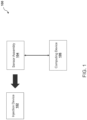
- environment 100 may include injection device 102, sensor assembly 104, and/or computing device 106.
- the number and arrangement of devices and systems shown in FIG. 1 is provided as an example. There may be additional devices and/or systems, fewer devices and/or systems, different devices and/or systems, or differently arranged devices and/or systems than those shown in FIG. 1 .
- two or more devices and/or systems shown in FIG. 1 may be implemented within a single device and/or system, or a single device and/or system shown in FIG. 1 may be implemented as multiple, distributed devices and/or systems.
- a set of devices and/or systems (e.g., one or more devices or systems) of environment 100 may perform one or more functions described as being performed by another set of devices and/or systems of environment 100.
- Injection device 102 may be configured to perform an injection operation to deliver a dose of medicament to a user.
- Injection device 102 may include injection devices with or without injection needles.
- Injection device 102 may be a disposable type injection device (e.g., a single use injection device, etc.) or a re-usable type injection device.
- Injection device 102 may include an auto injector, a pen injector, a wearable injector, and/or a passive needle guard.
- injection device 102 may include the BD Intevia TM autoinjector, the BD Libertas TM wearable autoinjector, the BD Sonic TM autoinjector, and/or the BD UltraSafe Plus TM passive needle guard for a pre-filled ISO standard glass syringe. Further details regarding non-limiting embodiments or aspects injection device 102 are provided below with regard to FIGS. 3A, 3B , and 4A-4C .
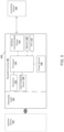
- sensor assembly 104 may include disposable label 130 configured to be attached to injection device 102 and/or a reusable housing 150 removably connected to disposable label 130.
- Disposable label 130 may include a flexible and/or tear-able (or breakable) substrate.
- disposable label 130 may be formed of paper, tamper evident tape, one or more polymers (e.g., PET, etc.), a flexible printed circuit board (PCB), or any combination thereof.
- Disposable label 130 may include an electrically conductive trace 132 (e.g., a circuit, etc.).
- electrically conductive trace 132 may be on a surface of and/or located within (e.g., integrated with, housed within, not exposed by, etc.) disposable label 130.
- electrically conductive trace 132 may include a conductive material applied to disposable label 130 by at least one of the following processes: printing (e.g., an inkjet printing, screen printing, etc.), metal deposition and/or etching, flexography, or any combination thereof.
- Portion 134 of disposable label 130 may be configured to be altered (e.g., bent, torn, broken, etc.). Alteration of portion 134 of disposable label 130 may cause a corresponding portion of electrically conductive trace 132 to be altered. For example, a first portion of electrically conductive trace 132 may be configured to be altered in response to an operation of injection device 102.
- portion 134 of disposable label 130 may be pre-cut, perforated, and/or the like, and tearing and/or breaking portion 134 of disposable label 130 may cause the corresponding portion of electrically conductive trace 132 to be torn and/or broken, thereby altering a state of a circuit formed by electrically conductive trace 132 (e.g., opening the circuit, closing the circuit, changing a resistance of the circuit, changing a voltage or a current flowing through the circuit, etc.).
- a first portion of disposable label 130 including at least a portion of electrically conductive trace 132 may be attached to a removable and/or actuatable element of injection device 102 (e.g., a cap, a button, etc.) and a remainder of disposable label 130, which is attached to the first portion via portion 134, may be attached elsewhere to injection device 102, and removal and/or actuation of the removable and/or actuatable element of injection device 102 (e.g., a cap, a button, etc.) may cause the tearing and/or breaking of portion 134 of disposable label 130, thereby causing the corresponding portion of electrically conductive trace 132 to be torn and/or broken to alter the state of the circuit formed by electrically conductive trace 132.
- a removable and/or actuatable element of injection device 102 e.g., a cap, a button, etc.
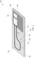
- FIGS. 3A and 3B are perspective views of an implementation 300 of non-limiting embodiments or aspects of sensor assembly 104 for injection device 102.
- a first portion of disposable label 130 including at least a portion of electrically conductive trace 132 may be attached to a cap of injection device 102 and a remainder of disposable label 130 may be attached to a body of injection device 102.
- removal of the cap of injection device 102 may cause the tearing and/or breaking of portion 134 of disposable label 130, thereby causing the corresponding portion of electrically conductive trace 132 to be torn and/or broken to alter the state of the circuit formed by electrically conductive trace 132.
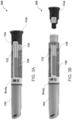
- FIGS. 4A-4C are perspective views of an implementation 400 of non-limiting embodiments or aspects of sensor assembly 104 for injection device 102.
- a first portion of disposable label 130 including at least a portion of electrically conductive trace 132 may be attached to a button of injection device 102 and a remainder of disposable label 130 may be attached to a body of injection device 102.
- actuation of the button of injection device 102 may cause the tearing and/or breaking of portion 134 of disposable label 130, thereby causing the corresponding portion of electrically conductive trace 132 to be torn and/or broken to alter the state of the circuit formed by electrically conductive trace 132.
- FIG. 4A a first portion of disposable label 130 including at least a portion of electrically conductive trace 132 may be attached to a button of injection device 102 and a remainder of disposable label 130 may be attached to a body of injection device 102.
- actuation of the button of injection device 102 may cause the tearing and/or breaking of portion 134 of disposable label 130
- FIG. 4C shows an alternative location of sensor assembly 104 where a first portion of disposable label 130 including at least a portion of electrically conductive trace 132 may be attached to a cover of injection device 102 and a remainder of disposable label 130 may be attached to a body of injection device 102. Removal of the cover of injection device 102 may cause the tearing and/or breaking of portion 134 of disposable label 130, thereby causing the corresponding portion of electrically conductive trace 132 to be torn and/or broken to alter the state of the circuit formed by electrically conductive trace 132.
- disposable label 130 includes an adhesive layer 136.
- adhesive layer 136 may adhere disposable label 130 to injection device 102 and/or a packing and/or container for sensor assembly 104.
- electrically conductive trace 132 may be on a first face of disposable label 130 (e.g., a same face of disposable label 130 to which reusable housing 150 is attached, etc.), and adhesive layer 136 may be on a second face of disposable label 130 opposite the first face of disposable label 130.
- disposable layer 130 includes sensor(s) 137.
- sensor(s) 137 may include at least one of the following: an optical sensor (e.g. a printed photodetector, etc.), a temperature sensor, a force sensor, (e.g., a force resistive sensor, a membrane switch, etc.) or any combination thereof.
- sensor(s) 137 may be electrically coupled to the electrically conductive trace 132.
- sensor(s) 137 may be used instead of, or in addition to, portion 134 for detecting a removal and/or actuation of a removable and/or actuatable element of injection device 102 (e.g., a cap, a button, etc.).
- a photodetector may be used to sense ambient light when a cap of injection device 102 is removed
- a temperature sensor or force sensor may be used to sense a temperature change or a force applied to a surface (e.g., using force resistive sensors printed on label 130, a membrane switch on label 130, etc.) when a user actuates a button of injection device 102, and/or the like.
- disposable label 130 includes battery 138 and/or memory 139.
- battery 138 and/or memory 130 may be connected to electrically conductive trace 132.
- Battery 138 may provide power to components of reusable housing 150 (e.g., in response to the alteration of electrically conductive trace 132, etc.) when reusable housing 150 is attached to disposable label 130.
- Battery 138 may include a flexible battery, a thin film battery, a printed battery, or any combination thereof.
- Memory 139 may store a unique identifier associated with disposable label 130 and/or injection device 102.
- the unique identifier may be accessed by and/or provided to components of reusable housing 150 (e.g., a processor, etc.) when reusable housing 150 is attached to disposable label 130 (e.g., in response to the alteration of electrically conductive trace 132, etc.).
- components of reusable housing 150 e.g., a processor, etc.
- disposable label 130 e.g., in response to the alteration of electrically conductive trace 132, etc.
- Reusable housing 150 may include (e.g., carry, house, encompass, etc.) processor 152 and/or wireless communication device 154.
- Processor 152 may be removably electrically coupled to electrically conductive trace 132.
- processor 152 is configured to be activated in response to an alteration of a portion of electrically conductive trace 132 (e.g., in response to opening the circuit, closing the circuit, changing a resistance of the circuit, changing a voltage or a current flowing through the circuit, etc.).
- the alteration of electrically conductive trace 132 may cause processor 152 to wake up, from a deep-sleep mode.
- a circuit formed by electrically conductive trace 132 may be intact in an initial state and operate as a closed switch, and when the user activates or operates injection device 102 and tears apart disposable label 130, electrically conductive trace 132 may be broken and operate as an open switch.
- a circuit formed by electrically conductive trace 132 may have as an initial state a closed circuit, an initial resistance, an initial voltage, an initial current, or any combination thereof and, after alteration, the circuit formed by electrically conductive trace 132 may have as a different state an open circuit, a second resistance, a second voltage, a second current, or any combination thereof.
- processor 152 and wireless communication device 154 are implemented in a single system-on-chip component.
- Wireless communication device 154 may be configured to wirelessly communicate with computing device 106.
- wireless communication device 154 may be configured to communicate information associated a use and/or operation of injection device 102 (e.g., information associated with an alteration of electrically conductive trace 132, sensor data, a unique identifier, etc.) to computing device 106.
- information associated a use and/or operation of injection device 102 e.g., information associated with an alteration of electrically conductive trace 132, sensor data, a unique identifier, etc.
- wireless communication device 154 includes one or more computing devices, chips, contactless transmitters, contactless transceivers, NFC transmitters, RFID transmitters, contact based transmitters, Bluetooth transceivers ® and/or the like that enables wireless communication device 154 to receive information directly from and/or communicate information directly to computing device 106 via a short range wireless communication connection (e.g., a communication connection that uses NFC protocol, a communication connection that uses Radio-frequency identification (RFID), a communication connection that uses a Bluetooth ® wireless technology standard, a communication protocol that uses a Zigbee wireless technology standard, a communication protocol that uses an Ant wireless technology standard, and/or the like).
- a short range wireless communication connection e.g., a communication connection that uses NFC protocol, a communication connection that uses Radio-frequency identification (RFID), a communication connection that uses a Bluetooth ® wireless technology standard, a communication protocol that uses a Zigbee wireless technology standard, a communication protocol that uses an Ant wireless technology standard, and/or the like.
- reusable housing 150 includes (e.g., carries, houses, encompasses, etc.) sensor(s) 155, user feed back device 156, RTC 157, power source 158, and/or member 159.
- Sensor(s) 155 may include at least one of the following: a vibration sensor, an accelerometer, an optical sensor, a magnetic sensor, or any combination thereof.
- sensor(s) 155 is configured to detect a movement of a component of injection device 102 associated with an injection operation of injection device 102.
- sensor 155 may be configured to detect a movement (e.g., a movement, a displacement, etc.) of at least one of a piston, a stopper of a plunger, a rod of the plunger, and a mobile trigger that initiates or triggers the movement of the plunger.
- Processor 152 may be programmed and/or configured to determine, based on a state of electrically conductive trace 132, a signal or sensor data received from sensor(s) 137, and/or a signal or sensor data received from sensor(s) 155, information associated with a use and/or operation of injection device 102.
- information associated with a use and/or operation of injection device 102 includes at least one of the following: a time of removal of a cap of injection device 102, a time of removal of a cover of injection device 102, a time of actuation of a button of injection device 102, a start time of an injection operation, a duration of the injection operation, a speed of the injection operation, a back pressure profile of the injection operation, or any combination thereof.
- Processor 152 may store information associated with a use and/or operation of injection device 102 in memory 154.
- User feedback device 156 may be configured to provide an indication associated with an injection operation and/or information associated a use and/or operation of injection device 102 to a user.
- user feedback device 150 may include at least one of the following: a display, a light-emitting diode (LED), an audio output device (e.g., a buzzer, a speaker, etc.), or any combination thereof.
- RTC 157 may include a computer clock (e.g., in the form of an integrated circuit, etc.) that keeps track of the current time.
- processor 152 may time stamp information associated with a use and/or operation of injection device 102 based on the current time of RTC 157 (e.g., a cap removal time, a button actuation time, etc.).
- Power source 158 may be configured to power processor 152, wireless communication device 154, sensor(s) 155, user feedback device 156, RTC 157, and/or memory 159.
- power source 152 may include a battery (e.g., a rechargeable battery, a disposable battery, etc.).
- Memory 159 may be configured to store information associated a use and/or operation of injection device 102.
- memory 159 stores a unique identifier associated with reusable housing 150 and/or injection device 102.
- the unique identifier may be accessed by and/or provided to processor 152 in response to the alteration of electrically conductive trace 132.
- computing device 106 may include one or more devices capable of receiving information and/or data from sensor assembly 104 and/or communicating information and/or data to sensor assembly 104.
- computing device 106 may include a computing device, a server, a group of servers, a mobile device, a group of mobile devices, and/or the like.
- computing device 106 includes one or more computing devices, chips, contactless transmitters, contactless transceivers, NFC transmitters, RFID transmitters, contact based transmitters, and/or the like that enables computing device 106 to receive information directly from and/or communicate information directly to wireless communication device 154 via a short range wireless communication connection (e.g., a communication connection that uses NFC protocol, a communication connection that uses Radio-frequency identification (RFID), a communication connection that uses a Bluetooth ® wireless technology standard, a communication protocol that uses a Zigbee wireless technology standard, a communication protocol that uses an Ant wireless technology standard, and/or the like).
- computing device 106 may include and/or upload information and/or data to an electronic data management system, such as a hospital record system, a system used during a clinical trial to collect the trial related information, and/or the like.
- FIG. 6 is a diagram of an implementation 600 of non-limiting embodiments or aspects of sensor assembly 104.
- disposable label 130 may include further electrically conductive trace 133, and processor 152 may be removably electrically coupled to the further electrically conductive trace.
- further electrically conductive trace may be the same as or similar to electrically conductive trace 132, except that a second portion of disposable label 130 including at least a portion of further electrically conductive trace 133 may be attached to a different removable and/or actuatable element of injection device 102 (e.g., a cap, a button, etc.) than the first portion of disposable label 130 including at least a portion of electrically conductive trace 132.
- a portion 135 of further electrically conductive 133 trace may be configured to be altered in response to a second operation of injection device 102 different than the first operation of injection device 102 in response to which the portion 134 of electrically conductive trace 132 is altered.
- the first operation of injection device 132 may include removal of a cap or a cover of injection device 102
- the second operation of injection device 102 may include actuation of a button of injection device 102 or a deployment of a needle shield of injection device 102.
- a second portion of an electrically conductive trace (e.g., electrically conductive trace 132, further electrically conductive trace 133, etc.) is configured to be altered in response to a second operation of injection device 102 different than the first operation of the injection device in response to which a first portion of the electrically conductive trace is altered.
- disposable label 130 may include portions 135a, 135b, ...
- disposable label 130 may include a plurality of portions respectively including first resistor R1, second resistor R2, and third resistor R3 respectively connected to reusable housing 150 and each other via alterable portions 135a, 135b, and 135n.
- a first portion of disposable label 130 including at least a portion of further electrically conductive trace 133 may be attached to a removable and/or actuatable element of injection device 102 (e.g., a cap, a button, etc.) and another portion of disposable label 130, which is attached to the first portion via portion 135n (e.g., including resistor R2, etc.), may be attached elsewhere to injection device 102 (e.g., another removable and/or actuatable element of injection device 102, etc.), and removal and/or actuation of the removable and/or actuatable element of injection device 102 (e.g., the cap, the button, etc.) may cause the tearing and/or breaking of portion 135n of disposable label 130, thereby causing the corresponding portion of further electrically conductive trace 133 to be torn and/or broken to alter the state of the circuit formed by further electrically conductive trace 133, and removal and/or
- the first operation of injection device 102 may include removal of a cap or a cover of injection device 102
- the second operation of injection device 102 may include actuation of a button of injection device 102 or a deployment of a needle shield of injection device 102.
- a further portion of disposable label 130 which is attached to the another portion via portion 135b (e.g., including resistor R1, etc.), may be attached elsewhere to injection device 102 (e.g., a further removable and/or actuatable element of injection device 102, etc.), and removal and/or actuation of the further removable and/or actuatable element of injection device 102 may cause the tearing and/or breaking of the portion 135a of disposable label 130, thereby causing the corresponding portion of further electrically conductive trace 133 to be torn and/or broken to alter the state of the circuit formed by further electrically conductive trace 133.
- an alteration caused to the state of the circuit may be different in response to tearing and/or breaking each of portions 135a, 135b, ... 135n (e.g., an alteration may open the circuit, close the circuit, change a resistance of the circuit, change a voltage or a current flowing through the circuit, etc.).
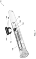
- FIG. 7 is a diagram of an implementation 700 of non-limiting embodiments or aspects of sensor assembly 104.
- disposable label 130 may include a plurality of first conductive pads 702 electrically coupled to electrically conductive trace 132 (and/or further electrically conductive trace 133), and reusable housing 150 may include a plurality of spring contacts 704 electrically coupled to processor 152 and removably electrically coupled to the plurality of first conductive pads 702.
- Reusable housing 150 may include a rigid deformable clip 706 configured to clip onto an exterior surface of injection device 102.
- rigid deformable clip 706 may include a half-pipe shape, with a material forming the half-pipe shape being configured to deform around and grasp an exterior surface of injection device 102 when clip 706 is pressed onto injection device 102 to contact the plurality of first conductive pads 702 with the plurality of spring contacts 704.
- Reusable housing 150 may be attached to and/or integrated with rigid deformable clip 706.
- reusable housing 150 may be attached to rigid deformable clip 706 via a clip, a snap fit, an adhesive, and/or other mechanical interface.
- Rigid deformable clip 706 may be configured and/or dimensioned according to a type (e.g., size, model, etc.) of injection device 102.
- disposable label 130 includes a plurality of first conductive pads electrically coupled to electrically conductive trace 132 (and/or further electrically conductive trace 133), reusable housing 150 includes a plurality of second conductive pads coupled to processor 152 and removably electrically coupled to the plurality of first conductive pads via a conductive adhesive applied to at least one of the plurality of first conductive pads and the plurality of second conductive pads.
- reusable housing 150 includes a plurality of second conductive pads coupled to processor 152 and removably electrically coupled to the plurality of first conductive pads via a conductive adhesive applied to at least one of the plurality of first conductive pads and the plurality of second conductive pads.
- disposable label 130, reusable housing 150, the plurality of first conductive pads, and/or the plurality of second conductive pads may include an adhesive layer configured to hold the plurality of first conductive pads in contact with the plurality of second conductive pads (and/or disposable label 130 in contact with reusable housing 150).
- FIG. 8 is a diagram of an implementation 800 of non-limiting embodiments or aspects of sensor assembly 104.
- disposable label 130 may include at least one connector 802 extending from disposable label 130
- reusable housing 150 may include at least one port 804 in which the at least one connector 802 is received
- the at least one connector 802 may include a plurality of first electrical connectors (e.g., wires, pins, etc.) electrically coupled to electrically conductive trace 132 (and/or further electrically conductive trace 133) and removably electrically coupled to a plurality of second electrical connectors (e.g., wires, pins, etc.) of the at least one port 804, with the plurality of second electrical connectors 804 electrically coupled to processor 152.
- the at least one connector 802 is press fit in the at least one port 804.
- the at least one connector 802 includes a plurality of connectors 802, and the at least one port 804 includes a plurality of ports 804 corresponding to the plurality of connectors 802.
- each connector of the plurality of connectors includes a single first electrical connector (e.g., a single wire, a single pin, etc.), and each port of the plurality of ports includes a single second electrical connector (e.g., a single wire, a single pin, etc.).
- FIG. 9 is a diagram of an implementation 900 of non-limiting embodiments or aspects of a system including sensor assembly 104.
- a system may include injection device 102, sensor assembly(s) 104, and/or container 902.
- Disposable label 130 of sensor assembly 104 may include an electrically conductive trace (e.g., electrically conductive trace 132, further electrically conductive trace 133, etc.) with a portion of disposable label 130 including the electrically conductive trace attached to container 902.
- an electrically conductive trace e.g., electrically conductive trace 132, further electrically conductive trace 133, etc.
- a portion e.g., portion 134, portion(s) 135a, 135b, ...
- reusable housing 150 may be reused with multiple disposable labels 130 and/or injection devices 102.
- container 902 may include multiple disposable labels 130 and/or injection devices 102 and a reusable housing 150, and reusable housing 150 may be attached a different disposable label 130/injection device 102 each time a new disposable label 130/injection device 102 is removed from container 902.
- a cost may be lower than disposing of an entire module with each injection device, a pairing process between module and computing device 106, if any, may only be performed once, a user may be asked to bring back to a doctor (or a clinical research associate in the case of a clinical trial) only the reusable housing (avoiding manipulation of sharps) for reconciliation or adherence purposes, and any applicable recycling process requiring taking apart electronic components may be eased.
Landscapes
- Health & Medical Sciences (AREA)
- Engineering & Computer Science (AREA)
- Heart & Thoracic Surgery (AREA)
- Public Health (AREA)
- Biomedical Technology (AREA)
- Anesthesiology (AREA)
- Hematology (AREA)
- Life Sciences & Earth Sciences (AREA)
- Animal Behavior & Ethology (AREA)
- General Health & Medical Sciences (AREA)
- Veterinary Medicine (AREA)
- Vascular Medicine (AREA)
- Pulmonology (AREA)
- Computer Hardware Design (AREA)
- Microelectronics & Electronic Packaging (AREA)
- Physics & Mathematics (AREA)
- General Physics & Mathematics (AREA)
- Theoretical Computer Science (AREA)
- Infusion, Injection, And Reservoir Apparatuses (AREA)
- Arrangements For Transmission Of Measured Signals (AREA)
- Measuring Volume Flow (AREA)
Priority Applications (2)
| Application Number | Priority Date | Filing Date | Title |
|---|---|---|---|
| EP25199949.6A EP4636645A2 (de) | 2020-08-05 | 2020-08-05 | Sensoranordnung und system |
| EP23208227.1A EP4296895B1 (de) | 2020-08-05 | 2020-08-05 | Sensoranordnung und system |
Applications Claiming Priority (2)
| Application Number | Priority Date | Filing Date | Title |
|---|---|---|---|
| EP23208227.1A EP4296895B1 (de) | 2020-08-05 | 2020-08-05 | Sensoranordnung und system |
| EP20305900.1A EP3951658B1 (de) | 2020-08-05 | 2020-08-05 | Sensoranordnung und system |
Related Parent Applications (2)
| Application Number | Title | Priority Date | Filing Date |
|---|---|---|---|
| EP20305900.1A Division-Into EP3951658B1 (de) | 2020-08-05 | 2020-08-05 | Sensoranordnung und system |
| EP20305900.1A Division EP3951658B1 (de) | 2020-08-05 | 2020-08-05 | Sensoranordnung und system |
Related Child Applications (2)
| Application Number | Title | Priority Date | Filing Date |
|---|---|---|---|
| EP25199949.6A Division-Into EP4636645A2 (de) | 2020-08-05 | 2020-08-05 | Sensoranordnung und system |
| EP25199949.6A Division EP4636645A2 (de) | 2020-08-05 | 2020-08-05 | Sensoranordnung und system |
Publications (4)
| Publication Number | Publication Date |
|---|---|
| EP4296895A2 true EP4296895A2 (de) | 2023-12-27 |
| EP4296895A3 EP4296895A3 (de) | 2024-03-27 |
| EP4296895B1 EP4296895B1 (de) | 2025-10-08 |
| EP4296895C0 EP4296895C0 (de) | 2025-10-08 |
Family
ID=72145327
Family Applications (3)
| Application Number | Title | Priority Date | Filing Date |
|---|---|---|---|
| EP25199949.6A Pending EP4636645A2 (de) | 2020-08-05 | 2020-08-05 | Sensoranordnung und system |
| EP20305900.1A Active EP3951658B1 (de) | 2020-08-05 | 2020-08-05 | Sensoranordnung und system |
| EP23208227.1A Active EP4296895B1 (de) | 2020-08-05 | 2020-08-05 | Sensoranordnung und system |
Family Applications Before (2)
| Application Number | Title | Priority Date | Filing Date |
|---|---|---|---|
| EP25199949.6A Pending EP4636645A2 (de) | 2020-08-05 | 2020-08-05 | Sensoranordnung und system |
| EP20305900.1A Active EP3951658B1 (de) | 2020-08-05 | 2020-08-05 | Sensoranordnung und system |
Country Status (10)
| Country | Link |
|---|---|
| US (1) | US20230285681A1 (de) |
| EP (3) | EP4636645A2 (de) |
| JP (2) | JP7768973B2 (de) |
| CN (1) | CN116324801A (de) |
| AU (1) | AU2021319810A1 (de) |
| BR (1) | BR112023002162A2 (de) |
| CA (1) | CA3188435A1 (de) |
| ES (1) | ES2971537T3 (de) |
| MX (1) | MX2023001513A (de) |
| WO (1) | WO2022029045A1 (de) |
Families Citing this family (1)
| Publication number | Priority date | Publication date | Assignee | Title |
|---|---|---|---|---|
| WO2023202884A1 (en) * | 2022-04-19 | 2023-10-26 | Shl Medical Ag | A label assembly of a medicament delivery device |
Family Cites Families (7)
| Publication number | Priority date | Publication date | Assignee | Title |
|---|---|---|---|---|
| US6255959B1 (en) * | 1999-08-12 | 2001-07-03 | Micron Technology, Inc. | Electrical apparatuses, methods of forming electrical apparatuses, and termite sensing methods |
| WO2006002667A1 (de) * | 2004-06-30 | 2006-01-12 | Fraunhofer-Gesellschaft zur Förderung der angewandten Forschung e.V. | Blisterpackung |
| DE102011050196A1 (de) * | 2010-05-06 | 2011-11-10 | Degudent Gmbh | RFID-Label |
| EP3021245A1 (de) * | 2014-10-06 | 2016-05-18 | Carebay Europe Ltd. | Informationsbereitstellungssystem |
| DK3573689T3 (da) * | 2017-01-26 | 2022-07-04 | Sanofi Aventis Deutschland | Fleksible moduler til injektionsanordninger |
| DK3731899T3 (da) * | 2017-12-28 | 2025-01-13 | Sanofi Sa | Monteringsadapter til injektionsanordning og tilbehørsanordning |
| WO2019162222A1 (en) * | 2018-02-26 | 2019-08-29 | Haselmeier Ag | Dosage determination using electrical conductivity in an injection device |
-
2020
- 2020-08-05 EP EP25199949.6A patent/EP4636645A2/de active Pending
- 2020-08-05 EP EP20305900.1A patent/EP3951658B1/de active Active
- 2020-08-05 ES ES20305900T patent/ES2971537T3/es active Active
- 2020-08-05 EP EP23208227.1A patent/EP4296895B1/de active Active
-
2021
- 2021-07-30 MX MX2023001513A patent/MX2023001513A/es unknown
- 2021-07-30 CA CA3188435A patent/CA3188435A1/en active Pending
- 2021-07-30 WO PCT/EP2021/071488 patent/WO2022029045A1/en not_active Ceased
- 2021-07-30 CN CN202180068791.XA patent/CN116324801A/zh active Pending
- 2021-07-30 JP JP2023507988A patent/JP7768973B2/ja active Active
- 2021-07-30 AU AU2021319810A patent/AU2021319810A1/en active Pending
- 2021-07-30 US US18/040,510 patent/US20230285681A1/en active Pending
- 2021-07-30 BR BR112023002162A patent/BR112023002162A2/pt unknown
-
2025
- 2025-10-30 JP JP2025183885A patent/JP2026010227A/ja active Pending
Also Published As
| Publication number | Publication date |
|---|---|
| JP7768973B2 (ja) | 2025-11-12 |
| ES2971537T3 (es) | 2024-06-05 |
| EP3951658B1 (de) | 2023-12-20 |
| EP4296895B1 (de) | 2025-10-08 |
| BR112023002162A2 (pt) | 2023-03-14 |
| EP4296895A3 (de) | 2024-03-27 |
| AU2021319810A1 (en) | 2023-03-23 |
| EP4296895C0 (de) | 2025-10-08 |
| EP4636645A2 (de) | 2025-10-22 |
| CN116324801A (zh) | 2023-06-23 |
| EP3951658A1 (de) | 2022-02-09 |
| EP3951658C0 (de) | 2023-12-20 |
| JP2023536754A (ja) | 2023-08-29 |
| WO2022029045A1 (en) | 2022-02-10 |
| CA3188435A1 (en) | 2022-02-10 |
| US20230285681A1 (en) | 2023-09-14 |
| MX2023001513A (es) | 2023-04-13 |
| JP2026010227A (ja) | 2026-01-21 |
Similar Documents
| Publication | Publication Date | Title |
|---|---|---|
| EP3443446B1 (de) | Elektronische vorrichtung mit kraftsensor | |
| US10108892B2 (en) | Wireless tag apparatus and related medication compliance monitoring techniques | |
| US9904885B2 (en) | Wireless medication compliance sensing device, system, and related methods | |
| US9396369B1 (en) | Electronic tag transmissions corresponding to physical disturbance of tag | |
| KR101700864B1 (ko) | 스마트 패키지 | |
| US20190204868A1 (en) | Electronic device and control method therefor | |
| KR102460543B1 (ko) | 전자 펜을 갖는 전자 장치 및 전자 펜 삽입 인식 방법 | |
| JP2026010227A (ja) | センサーアセンブリおよびシステム | |
| US20180288149A1 (en) | Method and Apparatus for Updating Data | |
| US9471817B1 (en) | Action-triggered radio-frequency identification tag | |
| WO2022022342A1 (zh) | 设备配对方法、系统、配件设备及计算机可读存储介质 | |
| WO2018038368A1 (ko) | 디스플레이 장치, 디스플레이 장치를 포함하는 전자 장치 및 그 압력 감지 방법 | |
| KR102555213B1 (ko) | 스타일러스 펜을 이용하여 전자 장치를 잠금 해제하기 위한 장치 및 그에 관한 방법 | |
| KR20180026924A (ko) | 동작을 제어하는 전자 장치 및 방법 | |
| EP4225403B1 (de) | Injektionsvorrichtung mit sensoranordnung | |
| EP3928815A1 (de) | Sensoranordnung und system | |
| CN218675986U (zh) | 触控笔、触控装置 | |
| CN203773504U (zh) | 触控装置及显示设备 | |
| US20240061530A1 (en) | Spurious hand signal rejection during stylus use | |
| CN207544498U (zh) | 手环 | |
| CN107357417A (zh) | 一种移动终端 |
Legal Events
| Date | Code | Title | Description |
|---|---|---|---|
| PUAI | Public reference made under article 153(3) epc to a published international application that has entered the european phase |
Free format text: ORIGINAL CODE: 0009012 |
|
| STAA | Information on the status of an ep patent application or granted ep patent |
Free format text: STATUS: THE APPLICATION HAS BEEN PUBLISHED |
|
| AC | Divisional application: reference to earlier application |
Ref document number: 3951658 Country of ref document: EP Kind code of ref document: P |
|
| AK | Designated contracting states |
Kind code of ref document: A2 Designated state(s): AL AT BE BG CH CY CZ DE DK EE ES FI FR GB GR HR HU IE IS IT LI LT LU LV MC MK MT NL NO PL PT RO RS SE SI SK SM TR |
|
| PUAL | Search report despatched |
Free format text: ORIGINAL CODE: 0009013 |
|
| AK | Designated contracting states |
Kind code of ref document: A3 Designated state(s): AL AT BE BG CH CY CZ DE DK EE ES FI FR GB GR HR HU IE IS IT LI LT LU LV MC MK MT NL NO PL PT RO RS SE SI SK SM TR |
|
| RIC1 | Information provided on ipc code assigned before grant |
Ipc: G06K 19/077 20060101AFI20240221BHEP |
|
| STAA | Information on the status of an ep patent application or granted ep patent |
Free format text: STATUS: REQUEST FOR EXAMINATION WAS MADE |
|
| 17P | Request for examination filed |
Effective date: 20240906 |
|
| RBV | Designated contracting states (corrected) |
Designated state(s): AL AT BE BG CH CY CZ DE DK EE ES FI FR GB GR HR HU IE IS IT LI LT LU LV MC MK MT NL NO PL PT RO RS SE SI SK SM TR |
|
| GRAP | Despatch of communication of intention to grant a patent |
Free format text: ORIGINAL CODE: EPIDOSNIGR1 |
|
| STAA | Information on the status of an ep patent application or granted ep patent |
Free format text: STATUS: GRANT OF PATENT IS INTENDED |
|
| INTG | Intention to grant announced |
Effective date: 20250507 |
|
| GRAS | Grant fee paid |
Free format text: ORIGINAL CODE: EPIDOSNIGR3 |
|
| GRAA | (expected) grant |
Free format text: ORIGINAL CODE: 0009210 |
|
| STAA | Information on the status of an ep patent application or granted ep patent |
Free format text: STATUS: THE PATENT HAS BEEN GRANTED |
|
| AC | Divisional application: reference to earlier application |
Ref document number: 3951658 Country of ref document: EP Kind code of ref document: P |
|
| AK | Designated contracting states |
Kind code of ref document: B1 Designated state(s): AL AT BE BG CH CY CZ DE DK EE ES FI FR GB GR HR HU IE IS IT LI LT LU LV MC MK MT NL NO PL PT RO RS SE SI SK SM TR |
|
| REG | Reference to a national code |
Ref country code: GB Ref legal event code: FG4D Ref country code: CH Ref legal event code: F10 Free format text: ST27 STATUS EVENT CODE: U-0-0-F10-F00 (AS PROVIDED BY THE NATIONAL OFFICE) Effective date: 20251008 |
|
| REG | Reference to a national code |
Ref country code: DE Ref legal event code: R096 Ref document number: 602020060364 Country of ref document: DE |
|
| REG | Reference to a national code |
Ref country code: IE Ref legal event code: FG4D |
|
| U01 | Request for unitary effect filed |
Effective date: 20251024 |
|
| U07 | Unitary effect registered |
Designated state(s): AT BE BG DE DK EE FI FR IT LT LU LV MT NL PT RO SE SI Effective date: 20251031 |