EP4296791B1 - Dispositif d'affichage de quantième - Google Patents
Dispositif d'affichage de quantième Download PDFInfo
- Publication number
- EP4296791B1 EP4296791B1 EP22179924.0A EP22179924A EP4296791B1 EP 4296791 B1 EP4296791 B1 EP 4296791B1 EP 22179924 A EP22179924 A EP 22179924A EP 4296791 B1 EP4296791 B1 EP 4296791B1
- Authority
- EP
- European Patent Office
- Prior art keywords
- interest
- display device
- mobile element
- dial
- visible
- Prior art date
- Legal status (The legal status is an assumption and is not a legal conclusion. Google has not performed a legal analysis and makes no representation as to the accuracy of the status listed.)
- Active
Links
Images


Classifications
-
- G—PHYSICS
- G04—HOROLOGY
- G04B—MECHANICALLY-DRIVEN CLOCKS OR WATCHES; MECHANICAL PARTS OF CLOCKS OR WATCHES IN GENERAL; TIME PIECES USING THE POSITION OF THE SUN, MOON OR STARS
- G04B19/00—Indicating the time by visual means
- G04B19/24—Clocks or watches with date or week-day indicators, i.e. calendar clocks or watches; Clockwork calendars
- G04B19/243—Clocks or watches with date or week-day indicators, i.e. calendar clocks or watches; Clockwork calendars characterised by the shape of the date indicator
- G04B19/24346—Clocks or watches with date or week-day indicators, i.e. calendar clocks or watches; Clockwork calendars characterised by the shape of the date indicator band-shaped
- G04B19/2436—Driving or releasing mechanisms wherein the date indicators are driven or released mechanically by a clockwork movement
- G04B19/24366—Driving or releasing mechanisms wherein the date indicators are driven or released mechanically by a clockwork movement driven or released stepwise by the clockwork movement
-
- G—PHYSICS
- G04—HOROLOGY
- G04B—MECHANICALLY-DRIVEN CLOCKS OR WATCHES; MECHANICAL PARTS OF CLOCKS OR WATCHES IN GENERAL; TIME PIECES USING THE POSITION OF THE SUN, MOON OR STARS
- G04B19/00—Indicating the time by visual means
- G04B19/04—Hands; Discs with a single mark or the like
-
- G—PHYSICS
- G04—HOROLOGY
- G04B—MECHANICALLY-DRIVEN CLOCKS OR WATCHES; MECHANICAL PARTS OF CLOCKS OR WATCHES IN GENERAL; TIME PIECES USING THE POSITION OF THE SUN, MOON OR STARS
- G04B19/00—Indicating the time by visual means
- G04B19/06—Dials
- G04B19/16—Shiftable dials, e.g. indicating alternately from 1 to 12 and from 13 to 24
- G04B19/166—Shiftable dials, e.g. indicating alternately from 1 to 12 and from 13 to 24 with rotating scales
-
- G—PHYSICS
- G04—HOROLOGY
- G04B—MECHANICALLY-DRIVEN CLOCKS OR WATCHES; MECHANICAL PARTS OF CLOCKS OR WATCHES IN GENERAL; TIME PIECES USING THE POSITION OF THE SUN, MOON OR STARS
- G04B19/00—Indicating the time by visual means
- G04B19/06—Dials
- G04B19/10—Ornamental shape of the graduations or the surface of the dial; Attachment of the graduations to the dial
-
- G—PHYSICS
- G04—HOROLOGY
- G04B—MECHANICALLY-DRIVEN CLOCKS OR WATCHES; MECHANICAL PARTS OF CLOCKS OR WATCHES IN GENERAL; TIME PIECES USING THE POSITION OF THE SUN, MOON OR STARS
- G04B19/00—Indicating the time by visual means
- G04B19/24—Clocks or watches with date or week-day indicators, i.e. calendar clocks or watches; Clockwork calendars
-
- G—PHYSICS
- G04—HOROLOGY
- G04B—MECHANICALLY-DRIVEN CLOCKS OR WATCHES; MECHANICAL PARTS OF CLOCKS OR WATCHES IN GENERAL; TIME PIECES USING THE POSITION OF THE SUN, MOON OR STARS
- G04B19/00—Indicating the time by visual means
- G04B19/24—Clocks or watches with date or week-day indicators, i.e. calendar clocks or watches; Clockwork calendars
- G04B19/243—Clocks or watches with date or week-day indicators, i.e. calendar clocks or watches; Clockwork calendars characterised by the shape of the date indicator
-
- G—PHYSICS
- G04—HOROLOGY
- G04B—MECHANICALLY-DRIVEN CLOCKS OR WATCHES; MECHANICAL PARTS OF CLOCKS OR WATCHES IN GENERAL; TIME PIECES USING THE POSITION OF THE SUN, MOON OR STARS
- G04B19/00—Indicating the time by visual means
- G04B19/24—Clocks or watches with date or week-day indicators, i.e. calendar clocks or watches; Clockwork calendars
- G04B19/243—Clocks or watches with date or week-day indicators, i.e. calendar clocks or watches; Clockwork calendars characterised by the shape of the date indicator
- G04B19/24306—Clocks or watches with date or week-day indicators, i.e. calendar clocks or watches; Clockwork calendars characterised by the shape of the date indicator combination of different shapes, e.g. bands and discs, discs and drums
Definitions
- the invention relates to the field of watchmaking, and in particular to that of displaying time indications of a timepiece, in particular a watch.
- the invention relates to a date display device.
- date display devices there are those which make it possible to indicate the current date by means of a movable index, typically a hand, moving on a dial of a watch, relative to a scale of characters made on said dial and uniformly distributed according to a circle or an arc of a circle.
- the characters are representative of dates.
- the hand is moved by a suitable date mechanism, well known to those skilled in the art, engaged with the hour wheel, so as to make a jump each day in order to indicate a new date.
- This date mechanism can be retrograde. In fact, it drives the hand in the opposite direction once it has passed through all the dates of a month, in order to indicate the first day of the following month.
- This type of date display device has limitations, for example in terms of readability and information provided. There are still date display devices, such as the document CH660663A .
- the present invention aims to increase the aesthetic appeal of date display devices with movable index, and in particular to facilitate their use by displaying additional information compared to the display devices of the state of the art.
- the invention may further comprise one or more of the following features, taken alone or in any technically possible combination.
- the portion of interest has an appearance identical to that of an external surface of the dial so as to hide from the user's view the character formed by the window through which the portion of interest is visible when the movable element occupies the active position.
- the marking area is arranged opposite at least the windows forming the characters representing the dates 29 to 31 when the mobile element occupies the rest position, the portion of interest having an appearance different from that of the dial and of said marking area, so as to highlight the characters representing the dates 29 to 31 when the mobile element occupies the active position.
- the mobile element comprises on an upper surface, in addition to the portion of interest, a surface portion capable of being visible through one or more windows corresponding to all or part of the marking zone, said marking zone of the mobile element having an appearance different from that of the portion of interest.
- the characters are distributed along at least one arc of a circle, the index being movable relative to the dial, the movable element being visible through all of the windows and having an axis of rotation coinciding with that of the index.
- the marking area and the portion of interest are distributed over the mobile element such that, when the latter occupies the rest position, the marking area is arranged facing all of the counters, and such that when the mobile element occupies the active position, the marking area is arranged facing part of the counters, the portion of interest being arranged facing the other counters.
- the movable element has a closed annular shape, the marking area and the portion of interest each being formed by a set of sectors arranged alternately one after the other so that two successive characters have a different appearance from one another.
- the mobile element comprises, on its upper surface, an additional sector of appearance different from those forming the marking zone and the portion of interest, said additional sector being interposed between two sectors having an appearance different from the appearance of said additional sector so that the latter constitutes the index.
- the sectors between which the additional sector is arranged have a color different from that of the marking area and the portion of interest.
- the display device comprises an excess thickness on which the marking area is made and arranged so as to be visible through all of the windows forming the characters representing the dates 1 to 28, said excess thickness and the movable element being arranged adjacently and having a thickness such that the upper surface of said movable element and the visible surface of said excess thickness extend substantially in the same plane.
- the mobile element has the shape of a lever, the date mechanism comprising a cam on the profile of which the lever is arranged to bear so that said cam, during its rotation, causes said lever to pivot between its active position and its rest position.
- the display device comprises two movable elements, one of which has a closed annular shape and the other of which has the shape of a lever.
- the dial is made of transparent material and comprises, on its surface facing the date mechanism, a thin opaque layer, the windows being made in said thin layer.
- the present invention relates to a date display device 10 comprising a dial 11 of a timepiece, for example a watch, having date indications, an index 12 movable in rotation relative to the dial 11 intended to indicate the current date, and a movable element 13 intended to cause a change in appearance of one or more date indications.
- a date display device 10 comprising a dial 11 of a timepiece, for example a watch, having date indications, an index 12 movable in rotation relative to the dial 11 intended to indicate the current date, and a movable element 13 intended to cause a change in appearance of one or more date indications.
- the date indications are arranged in the form of a scale of thirty-one characters 15, for example distributed along an arc of a circle, at least part of which is in the form of windows 150, as visible in the Figures 1a, 1c, 2a, 2c , 3a, 3c, 4a, 4c , 5a and 5c .
- the visible surface of the dial 11 is the surface of an external face 110.
- characters 15 representing dates 1 to 28 have a constant appearance and characters 15 representing dates 29 to 31 have a variable appearance depending on the length of the current month.
- the characters 15 representing the dates 1 to 28 can be formed by windows 150 revealing a marking area 160 for example made by a thin layer, as illustrated in the Figures 1a, 2a And 4a .
- the marking area 160 and the movable element 13 are visible by transparency on the Figures 1b, 2b , 3b and 4b to facilitate understanding of the invention. It should be noted, however, that this marking area 160 is normally only visible through the windows 150, the thin layer 112 being opaque.
- the mobile element 13 may or may not include a marking zone 160.
- the index 12 is mobile, for example in rotation around an axis concentric with the arc of a circle along which the characters 15 are distributed.
- the index 12 is formed by a needle.
- the dial 11 is made of transparent material, for example sapphire or glass, and comprises, on the surface of an internal face 111, a thin opaque layer 112, the windows 150 being preferentially made in said thin layer 112.
- the date display device 10 comprises an annual or perpetual calendar mechanism (not shown in the figures) configured to move the index 12 by one step per day, such that each position occupied by said index 12 designates one of the characters 15 corresponding to the date of the current day.
- an annual or perpetual calendar mechanism (not shown in the figures) configured to move the index 12 by one step per day, such that each position occupied by said index 12 designates one of the characters 15 corresponding to the date of the current day.
- Such a date mechanism is well known to those skilled in the art, it is therefore not described in detail below.
- the index 12 is driven from the date of the last day of the month, for example 28, 29, 30 or 31, to the date of the start of the month, by the annual or perpetual calendar mechanism.
- the internal face 111 is arranged opposite the date mechanism.
- This date mechanism is part of a 16 clock movement shown schematically on the Figures 1a, 1c, 2a, 2c , 3a, 3c, 4a and 4c .
- the dial 11 is superimposed on a plate of the watch movement 16 and the movable element 13 is interposed between said dial 11 and said plate.
- the movable element 13 is arranged between the dial 11 and the date mechanism and has on all or part of a surface arranged opposite said dial 11, called the “upper surface” 130, a portion of interest 131 having an appearance different from that of the marking zone 160.
- the portion of interest 131 may be constituted by a thin layer deposited on the movable element 13, as shown in the Figures 1c, 2c , 3c and 4c .
- the movable element 13 is kinematically connected to the date mechanism so that the latter is capable of driving said movable element 13 into an active position in which the portion of interest 131 is visible through at least one predetermined window 150 and into a rest position in which the portion of interest 131 is arranged set back from said at least one predetermined window 150.
- the portion of interest 131 when the movable element 13 occupies the active position, the portion of interest 131 is arranged opposite one or more windows 150 forming characters 15 materializing dates likely to be variable between two successive months, that is to say dates 29 to 31.
- the active position of the movable element 13 can be defined by several angular positions of the latter.
- the portion of interest 131 can be delimited by a stepped profile in order to be visible opposite one or more windows 150 depending on its angular position when it occupies the active position.
- the portion of interest 131 may have a different color from that presented by the marking area 160, and in particular, it may have a color identical to that of the dial 11. This characteristic has the effect of concealing the characters 15 opposite which the portion of interest 131 is arranged when the movable element 13 occupies the active position.
- the character(s) 15 formed by the windows 150 through which said portion of interest 131 is visible when the mobile element 13 occupies the active position are highlighted relative to the other characters 15.
- variable dates can be hidden, or on the contrary, highlighted relative to the rest of the dates, that is to say relative to dates 1 to 28, depending on the number of days in the current month.
- dates 29, 30 and/or 31 can be hidden or highlighted during months with less than thirty-one days, so that the user can identify the number of days in the current month.
- the mobile element 13 only has a portion of interest 131 visible through one or more windows 150 when the mobile element 13 occupies the active position. Furthermore, the marking area 160 is produced by a thin layer deposited on the plate of the watch movement 16, opposite all of the windows 150 forming the characters 15 representing the dates 1 to 31.
- the mobile element 13 comprises two surface portions capable of being visible through one or more windows 150.
- One of these portions corresponds to a part of the marking zone 160 and the other portion corresponds to the portion of interest 131.
- the movable element 13 is configured so that, when it occupies the rest position, the part of the marking zone 160 that it presents is arranged opposite at least all of the characters 15 representing the dates 29 to 31.
- the device 10 may include an additional thickness 17, as illustrated in the Figures 2a and 2c , fixed on the plate of the watch movement 16 and on which the marking area 160 is produced so that it is visible through all of the windows 150 forming the characters 15 representing the dates 1 to 28.
- the movable element 13 and the excess thickness 17 are arranged adjacent to each other and have a thickness such that the surfaces of said excess thickness 17 and of the movable element 13 visible through all of the windows 150 extend in the same plane.
- the marking area 160 can be deposited directly on the internal face 111 of the dial 11 in order to form the characters 15 representing for example the dates 1 to 28, as shown in the Figures 3a to 3c .
- the windows 150 are only made to form the characters 15 representing at least the dates 29 to 31.
- the marking area 160 is entirely produced on the movable element 13.
- the movable element 13 has an open annular shape and is movable in rotation about an axis coincident with that of the index 12.
- the movable element 13 is visible through all of the windows 150.
- the marking area 160 is visible through all of the windows 150, and when it occupies the active position, the second portion is visible through one or more windows 150 forming the characters 15 representing one or more of the dates 29 to 31, the rest of the windows 150 revealing said marking area 160.
- the movable element 13 is formed by a lever.
- the movable element 13 is arranged to bear by a free end against a profile of a cam (not shown in the figures) which the date mechanism comprises so that said cam, during its rotation, causes said movable element 13 to pivot between its active position and its rest position.
- the cam is rotated by one twelfth of a turn per month by a dedicated gear train, and its profile comprises several portions having different radii, including portions intended to receive the mobile element 13 in support so that it occupies the rest position, and including portions intended to receive the mobile element 13 in support so that it occupies different angular positions representative of its active position.
- the objective in these examples of embodiments of the invention is to move the movable element 13 so as to display the date number corresponding to the number of days in the current month.
- the movable element 13 may have a closed annular shape, as shown in the Figure 5b in another exemplary embodiment.
- the portion of interest 131 and the marking area 160 of the movable element 13 each comprise a plurality of sectors.
- the sectors of said portion of interest 131 and said marking area 160 are arranged alternately one after the other and each sector is sized so as to be arranged opposite a character 15.
- two successive characters 15 have a different appearance from each other, as visible on the figure 5c .
- the mobile element 13 is configured to be driven by the date mechanism by one step per day, a step corresponding to an angular value separating two successive windows 150.
- the display device 10 can thus, depending on the appearance of the portion of interest 131, highlight or conceal the characters 15 representing the even or odd dates, depending on whether the date of the current day is even or odd. This characteristic advantageously contributes to facilitating the reading of the dates and in particular of the date of the current day.
- the movable element 13 may comprise internal or external teeth in kinematic relation with a finger of an index drive wheel 12.
- the movable element 13 is preferably integral in rotation with the index 12.
- the objective in this exemplary embodiment is to move the movable element 13 so as to display only the even or odd dates, depending on whether the date of the current day is even or odd.
- the characters 15 are preferably formed by a series of numbers from 1 to 31.
- the present invention allows easy reading of these characters 15, even if they are arranged at a very short distance from each other, as visible by comparison of the Figure 5a , in which the movable element 13 is not shown, and of the figure 5c in which the movable element 13 is shown.
- the movable element 13 occupies the active position and the rest position alternately, relative to a given window.
- the mobile element 13 may further comprise an additional sector of appearance different from those of the marking zone 160 and the portion of interest 131, interposed between two sectors of said marking zone 160, between two sectors of said portion of interest 131, or between two other sectors identical to each other but of appearance different from that of said additional sector.
- This additional sector is dimensioned so as to be visible only through a single window 150 and to form the index 12, and thus to be able to do without a hand or any other index formed by an additional part. The additional sector is therefore visible to a user through the window 150 forming the character 15 representing the date of the current day.
- the marking area 160 of the mobile element 13 forms a sector visible through only one of the windows 150 so as to indicate the date of the current day, the portion of interest 131 defining two sectors extending on either side of said marking area 160 so as to be visible through all of the windows 150 except the window through which the sector of the marking area 160 is visible.
- the index 12 is constituted by said single sector formed by the marking zone 160. The user can thus simply and quickly identify the date of the current day on the dial 11.
- the display device 10 may comprise two movable elements 13, one of which has a closed annular shape, in a manner analogous for example to the movable element 13 described above in the exemplary embodiment shown in FIG. Figure 5b , and the other of which has the shape of a lever, in a manner analogous for example to the movable element 13 described above in the exemplary embodiment shown in the Figures 1a .
- the operations of the movable elements 13 are identical to the operations of those described respectively in the description of the exemplary embodiments shown in the Figures 1a And 5a has 5c , so that this example of a display device allows to benefit from the combination of their advantages.
- the character scale 15 extends along an arc of a semicircle. It is obvious that the character scale 15 can extend along an arc of a circle forming a more or less significant angle.
Landscapes
- Physics & Mathematics (AREA)
- General Physics & Mathematics (AREA)
- Electromechanical Clocks (AREA)
Description
- L'invention relève du domaine de l'horlogerie, et notamment de celui de l'affichage d'indications temporelles d'une pièce d'horlogerie, notamment d'une montre.
- Plus particulièrement, l'invention concerne un dispositif d'affichage de quantième.
- Parmi les dispositifs d'affichage de quantième, il existe ceux qui permettent d'indiquer la date courante par le biais d'un index mobile, typiquement une aiguille, se déplaçant sur un cadran d'une montre, par rapport à une échelle de caractères réalisés sur ledit cadran et répartis uniformément selon un cercle ou un arc de cercle. Les caractères sont représentatifs de quantièmes.
- L'aiguille est déplacée par un mécanisme de quantième approprié, bien connu de l'homme du métier, en prise avec la roue des heures, de sorte à effectuer un saut chaque jour afin d'indiquer un nouveau quantième.
- Ce mécanisme de quantième peut être rétrograde. En effet, il entraîne l'aiguille dans un sens inverse une fois qu'elle a parcouru l'ensemble des quantièmes d'un mois, afin d'indiquer le premier jour du mois suivant.
- Les dispositifs d'affichage de quantièmes sont notamment décrits en détail dans l'ouvrage « les montres compliquées » de François Lecoultre, publié aux Editions Simonin.
- Ce genre de dispositif d'affichage de quantième présente des limites, par exemple de lisibilité et d'informations fournies. Il existe encore des dispositifs d'affichage de quantième, tel que le document
CH660663A - La présente invention vise à augmenter l'attrait esthétique des dispositifs d'affichage de quantième à index mobile, et notamment à en faciliter l'usage en affichant des informations supplémentaires par rapport aux dispositifs d'affichage de l'état de la technique.
- L'invention résout les inconvénients précités en proposant un dispositif d'affichage de quantième comportant :
- un cadran comprenant des indications de quantièmes sous la forme d'une échelle de caractères, dont au moins une partie est sous forme de guichets,
- un index mobile par rapport au cadran,
- un mécanisme de quantième configuré pour entraîner l'index en déplacement d'un pas par jour, de sorte que chaque position occupée par ledit index désigne l'un des caractères, et
- un élément mobile agencé entre le cadran et le mécanisme de quantième présentant sur toute ou partie d'une surface disposée en regard dudit cadran, une portion d'intérêt, ledit élément mobile étant relié cinématiquement au mécanisme de quantième de sorte que ce dernier soit apte à l'entraîner dans une position active dans laquelle la portion d'intérêt est visible à travers au moins un guichet prédéterminé et dans une position de repos dans laquelle la portion d'intérêt est agencée en retrait dudit au moins un guichet prédéterminé et dans laquelle une zone de marquage est visible à travers ledit guichet prédéterminé.
- Dans des modes particuliers de réalisation, l'invention peut comporter en outre l'une ou plusieurs des caractéristiques suivantes, prises isolément ou selon toutes les combinaisons techniquement possibles.
- Dans des modes particuliers de réalisation, la portion d'intérêt présente un aspect identique à celui d'une surface externe du cadran de sorte à soustraire à la vue de l'utilisateur le caractère formé par le guichet à travers lequel la portion d'intérêt est visible lorsque l'élément mobile occupe la position active.
- Dans des modes particuliers de réalisation, la zone de marquage est agencée en regard au moins des guichets formant les caractères représentant les quantièmes 29 à 31 lorsque l'élément mobile occupe la position de repos, la portion d'intérêt présentant un aspect différent de celui du cadran et de ladite zone de marquage, de sorte à mettre en évidence les caractères représentant les quantièmes 29 à 31 lorsque l'élément mobile occupe la position active.
- Dans des modes particuliers de réalisation, l'élément mobile comporte sur une surface supérieure, en plus de la portion d'intérêt, une portion de surface susceptible d'être visible à travers un ou des guichets correspondant à tout ou partie de la zone de marquage, ladite zone de marquage de l'élément mobile présentant un aspect différent de celui de la portion d'intérêt.
- Dans des modes particuliers de réalisation, les caractères sont répartis selon au moins un arc de cercle, l'index étant mobile par rapport au cadran, l'élément mobile étant visible à travers l'ensemble des guichets et présentant un axe de rotation confondu avec celui de l'index.
- Dans des modes particuliers de réalisation, la zone de marquage et la portion d'intérêt sont réparties sur l'élément mobile de sorte que, lorsque ce dernier occupe la position de repos, la zone de marquage est agencée en vis-à-vis de l'ensemble des guichets, et de sorte que lorsque l'élément mobile occupe la position active, la zone de marquage est agencée en vis-à-vis d'une partie des guichets, la portion d'intérêt étant agencée en vis-à-vis des autres guichets.
- Dans des modes particuliers de réalisation, l'élément mobile présente une forme annulaire fermée, la zone de marquage et la portion d'intérêt étant chacune formées par un ensemble de secteurs agencés alternativement les uns à la suite des autres de sorte que deux caractères successifs présentent un aspect différent l'un de l'autre.
- Dans des modes particuliers de réalisation, l'élément mobile comporte, sur sa surface supérieure, un secteur supplémentaire d'aspect différent de ceux formant la zone de marquage et de la portion d'intérêt, ledit secteur supplémentaire étant interposé entre deux secteurs présentant un aspect différent de l'aspect dudit secteur supplémentaire de sorte que ce dernier constitue l'index.
- Dans des modes particuliers de réalisation, les secteurs entre lesquels est agencé le secteur supplémentaire présentent une couleur différente de celle de la zone de marquage et de la portion d'intérêt.
- Dans des modes particuliers de réalisation, le dispositif d'affichage comprend une surépaisseur sur laquelle est réalisée la zone de marquage et agencée de sorte à être visible à travers l'ensemble des guichets formant les caractères représentant les quantièmes 1 à 28, ladite surépaisseur et l'élément mobile étant agencés de façon adjacente et présentant une épaisseur telle que la surface supérieure dudit élément mobile et la surface visible de ladite surépaisseur s'étendent sensiblement dans un même plan.
- Dans des modes particuliers de réalisation, l'élément mobile présente la forme d'un levier, le mécanisme de quantième comportant une came sur le profil de laquelle le levier est agencé en appui de sorte que ladite came, lors de sa rotation, entraîne le pivotement dudit levier entre sa position active et sa position de repos.
- Dans des modes particuliers de réalisation, le dispositif d'affichage comprend deux éléments mobiles dont un présente une forme annulaire fermée et dont l'autre présente la forme d'un levier.
- Dans des modes particuliers de réalisation, le cadran est réalisé en matériau transparent et comporte, sur sa surface en vis-à-vis du mécanisme de quantième, une couche mince opaque, les guichets étant réalisés dans ladite couche mince.
- D'autres caractéristiques et avantages de l'invention apparaîtront à la lecture de la description détaillée suivante donnée à titre d'exemple nullement limitatif, en référence aux dessins annexés dans lesquels :
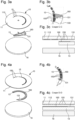
- la
figure 1a représente une vue en perspective éclatée d'un dispositif d'affichage de quantième selon un exemple de réalisation de l'invention ; - la
figure 1b représente schématiquement une vue de dessus d'un détail du dispositif de lafigure 1a ; - la
figure 1c représente schématiquement une vue en coupe selon le plan de coupe A-A du dispositif de lafigure 1b ; - la
figure 2a représente une vue en perspective éclatée d'un dispositif d'affichage de quantième selon un autre exemple de réalisation de l'invention ; - la
figure 2b représente schématiquement une vue de dessus d'un détail du dispositif de lafigure 2a ; - la
figure 2c représente schématiquement une vue en coupe selon le plan de coupe B-B du dispositif de lafigure 2b ; - la
figure 3a représente une vue en perspective éclatée d'un dispositif d'affichage de quantième selon encore un autre exemple de réalisation de l'invention ; - la
figure 3b représente schématiquement une vue de dessus d'un détail du dispositif de lafigure 3a ; - la
figure 3c représente schématiquement une vue en coupe selon le plan de coupe C-C du dispositif de lafigure 3b ; - la
figure 4a représente une vue en perspective éclatée d'un dispositif d'affichage de quantième selon encore un autre exemple de réalisation de l'invention ; - la
figure 4b représente schématiquement une vue de dessus d'un détail du dispositif de lafigure 4a ; - la
figure 4c représente schématiquement une vue en coupe selon le plan de coupe D-D du dispositif de lafigure 4b ; - la
figure 5a représente une vue schématique de dessus d'un cadran d'un dispositif d'affichage de quantième selon encore un autre exemple de réalisation de l'invention, sans élément mobile, le cadran comprenant des indications de quantièmes dont un est désigné par un index sous la forme d'une aiguille ; - la
figure 5b représente schématiquement une vue de dessus d'un élément mobile destiné à intégrer le dispositif de lafigure 5a ; - la
figure 5c représente schématiquement une vue de dessus du cadran de lafigure 5a avec lequel coopère l'élément mobile de lafigure 5b ; - la
figure 6 représente schématiquement une combinaison de deux éléments mobiles d'un dispositif d'affichage de quantième selon encore un autre exemple de réalisation de l'invention, lesdits éléments mobiles étant conformes respectivement à celui d'une desfigures 1a à 3c et à celui de lafigure 5b . - On note que les figures ne sont pas nécessairement dessinées à l'échelle pour des raisons de clarté.
- Comme le montrent schématiquement les
figures 1a à 6 , la présente invention porte sur un dispositif 10 d'affichage de quantième comportant un cadran 11 d'une pièce d'horlogerie, par exemple d'une montre, présentant des indications de quantièmes, un index 12 mobile en rotation par rapport au cadran 11 destiné à indiquer le quantième courant, et un élément mobile 13 destiné à provoquer un changement d'aspect d'une ou de plusieurs indications de quantièmes. - Dans l'ensemble des exemples de réalisation décrits ci-après, les indications de quantième sont agencées sous la forme d'une échelle de trente et un caractères 15, par exemple répartis selon un arc de cercle, dont au moins une partie est sous la forme de guichets 150, comme visible sur les
figures 1a, 1c, 2a, 2c ,3a, 3c, 4a, 4c ,5a et 5c . Il y a lieu de noter que, lorsque la surface visible à travers les guichets 150 présente un aspect différent de celui de la surface visible du cadran 11, les caractères 15 formés par les guichets 150 sont visibles pour un utilisateur, et lorsque la surface visible à travers les guichets 150 présente un aspect identique de celui de la surface visible du cadran 11, les caractères 15 sont dissimulés de la vue de l'utilisateur. La surface visible du cadran 11 est la surface d'une face externe 110. - Dans les exemples de réalisation représentés sur les
figures 1a à 4c , les caractères 15 représentant les quantièmes 1 à 28 présentent un aspect constant et les caractères 15 représentant les quantièmes 29 à 31 présentent un aspect variable selon la durée du mois courant. - Les caractères 15 représentant les quantièmes 1 à 28 peuvent être formés par des guichets 150 laissant apparaitre une zone de marquage 160 par exemple réalisée par une couche mince, tel que l'illustrent les
figures 1a, 2a et4a . Par ailleurs, la zone de marquage 160 et l'élément mobile 13 sont visibles par transparence sur lesfigures 1b, 2b ,3b et 4b pour faciliter la compréhension de l'invention. Il y a toutefois lieu de noter que cette zone de marquage 160 n'est normalement visible qu'à travers les guichets 150, la couche mince 112 étant opaque. Comme décrit en détail ci-après, selon l'exemple de réalisation considéré, l'élément mobile 13 peut comporter ou non une zone de marquage 160. - Par ailleurs, l'index 12 est mobile, par exemple en rotation autour d'un axe concentrique avec l'arc de cercle selon lequel sont répartis les caractères 15. Dans les exemples de réalisation représentés sur les figures, l'index 12 est formé par une aiguille.
- Préférentiellement, comme le montrent les
figures 1c, 2c ,3c et 4c , le cadran 11 est réalisé en matériau transparent, par exemple en saphir ou en verre, et comporte, sur la surface d'une face interne 111, une couche mince 112 opaque, les guichets 150 étant préférentiellement réalisés dans ladite couche mince 112. - Le dispositif 10 d'affichage de quantième selon l'invention comporte un mécanisme de quantième annuel ou perpétuel (non représenté sur les figures) configuré pour entraîner en déplacement l'index 12 d'un pas par jour, de sorte que chaque position occupée par ledit index 12 désigne l'un des caractères 15 correspondant au quantième du jour courant. Un tel mécanisme de quantième est bien connu de l'homme du métier, il n'est donc pas décrit en détail ci-après. De manière également connue en soi, au moment de passer au prochain mois, l'index 12 est entraîné depuis le quantième du dernier jour du mois, par exemple 28, 29, 30 ou 31, jusqu'au quantième de début de mois, par le mécanisme de quantième annuel ou perpétuel. La face interne 111 est agencée en regard du mécanisme de quantième.
- Ce mécanisme de quantième fait partie d'un mouvement horloger 16 représenté schématiquement sur les
figures 1a, 1c, 2a, 2c ,3a, 3c, 4a et 4c . - Dans les exemples de réalisation représentés sur les figures, le cadran 11 est superposé à une platine du mouvement horloger 16 et l'élément mobile 13 est interposé entre ledit cadran 11 et ladite platine.
- Avantageusement, l'élément mobile 13 est agencé entre le cadran 11 et le mécanisme de quantième et présente sur toute ou partie d'une surface disposée en regard dudit cadran 11, dite « surface supérieure » 130, une portion d'intérêt 131 présentant un aspect différent de celui de la zone de marquage 160. La portion d'intérêt 131 peut être constituée par une couche mince déposée sur l'élément mobile 13, comme le montrent les
figures 1c, 2c ,3c et 4c . - L'élément mobile 13 est relié cinématiquement au mécanisme de quantième de sorte que ce dernier soit apte à entraîner ledit élément mobile 13 dans une position active dans laquelle la portion d'intérêt 131 est visible à travers au moins un guichet 150 prédéterminé et dans une position de repos dans laquelle la portion d'intérêt 131 est agencée en retrait dudit au moins un guichet 150 prédéterminé.
- Dans les exemples de réalisation représentés sur les
figures 1a à 4c , lorsque l'élément mobile 13 occupe la position active, la portion d'intérêt 131 est agencée au regard d'un ou de plusieurs guichets 150 formant des caractères 15 matérialisant des quantièmes susceptibles d'être variables entre deux mois successifs, c'est-à-dire les quantièmes 29 à 31. Autrement dit, la position active de l'élément mobile 13 peut être définie par plusieurs positions angulaires de ce dernier. A cet effet, comme le montrent lesfigures 1a, 1b, 2a, 2b ,3a et 3b , la portion d'intérêt 131 peut être délimitée par un profil en escalier afin d'être visible en regard d'un ou de plusieurs guichets 150 suivant sa position angulaire lorsqu'il occupe la position active. - Par exemple, la portion d'intérêt 131 peut présenter une couleur différente de celle présentée par la zone de marquage 160, et en particulier, elle peut présenter une couleur identique à celle du cadran 11. Cette caractéristique a pour effet de dissimuler les caractères 15 en regard desquelles la portion d'intérêt 131 est agencée lorsque l'élément mobile 13 occupe la position active.
- Alternativement, si la portion d'intérêt 131 présente une couleur différente de celle du cadran 11 et de celle de la surface visible à travers les guichets 150 lorsque l'élément mobile 13 occupe la position de repos, le ou les caractères 15 formés par les guichet 150 à travers lesquels ladite portion d'intérêt 131 est visible lorsque l'élément mobile 13 occupe la position active sont mis en évidence par rapport aux autres caractères 15.
- Ainsi, grâce à l'invention, selon l'aspect de la portion d'intérêt 131, les quantièmes variables peuvent être dissimulés, ou au contraire, mis en évidence par rapport au reste des quantièmes, c'est-à-dire par rapport aux quantièmes 1 à 28, en fonction du nombre de jour du mois courant. En d'autres termes, les quantièmes 29, 30 et/ou 31 peuvent être dissimulés ou mis en évidence durant les mois de moins de trente et un jours, de sorte que l'utilisateur puisse identifier le nombre de jour du mois courant.
- Dans l'exemple de réalisation représenté sur les
figures 1a à 1c , l'élément mobile 13 présente uniquement une portion d'intérêt 131 visible à travers un ou des guichets 150 lorsque l'élément mobile 13 occupe la position active. Par ailleurs, la zone de marquage 160 est réalisée par une couche mince déposée sur la platine du mouvement horloger 16, en regard de l'ensemble des guichets 150 formant les caractères 15 représentant les quantièmes 1 à 31. - Contrairement à l'exemple de réalisation représenté sur les
figures 1a à 1c , dans les exemples de réalisation représentés sur lesfigures 2a à 3c , l'élément mobile 13 comporte deux portions de surface susceptibles d'être visibles à travers un ou des guichets 150. L'une de ces portions correspond à une partie de la zone de marquage 160 et l'autre portion correspond à la portion d'intérêt 131. - En particulier, comme illustré sur les
figures 2b ,3b et 4b , l'élément mobile 13 est configuré de sorte que, lorsqu'il occupe la position de repos, la partie de la zone de marquage 160 qu'il présente est agencée en regard au moins de l'ensemble des caractères 15 représentant les quantièmes 29 à 31. - Afin d'améliorer la qualité perçue de l'affichage de quantième, le dispositif 10 peut comporter une surépaisseur 17, telle qu'illustrée sur les
figures 2a et 2c , fixée sur la platine du mouvement horloger 16 et sur laquelle est réalisée la zone de marquage 160 de sorte que celle-ci soit visible à travers l'ensemble des guichets 150 formant les caractères 15 représentant les quantièmes 1 à 28. L'élément mobile 13 et la surépaisseur 17 sont agencés de façon adjacente l'un de l'autre et présentent une épaisseur telle que les surfaces de ladite surépaisseur 17 et de l'élément mobile 13 visibles à travers l'ensemble des guichets 150 s'étendent dans un même plan. - Alternativement, la zone de marquage 160 peut être déposée directement sur la face interne 111 du cadran 11 afin de former les caractères 15 représentant par exemple les quantièmes 1 à 28, tel que le montrent les
figures 3a à 3c . Dans cet exemple de réalisation, les guichets 150 sont uniquement réalisés pour former les caractères 15 représentant au moins les quantièmes 29 à 31. - Encore alternativement, dans l'exemple de réalisation représenté sur les
figures 4a à 4c , la zone de marquage 160 est entièrement réalisée sur l'élément mobile 13. - Plus particulièrement, dans cet exemple de réalisation, l'élément mobile 13 présente une forme annulaire ouverte et est mobile en rotation autour d'un axe confondu avec celui de l'index 12. L'élément mobile 13 est visible à travers l'ensemble des guichets 150. Autrement dit, lorsqu'il occupe la position de repos, la zone de marquage 160 est visible à travers tous les guichets 150, et lorsqu'il occupe la position active, la seconde portion est visible à travers un ou des guichets 150 formant les caractères 15 représentant un ou plusieurs des quantièmes 29 à 31, le reste des guichets 150 laissant apparaitre ladite zone de marquage 160.
- Dans les exemples de réalisation représentés sur les
figures 1a à 3c , l'élément mobile 13 est formé par un levier. - Dans l'ensemble des exemples de réalisation représentés sur les
figures 1a à 4c , l'élément mobile 13 est agencé en appui par une extrémité libre contre un profil d'une came (non représentée sur les figures) que comporte le mécanisme de quantième de sorte que ladite came, lors de sa rotation, entraîne le pivotement dudit élément mobile 13 entre sa position active et sa position de repos. - Plus particulièrement, la came est entraînée en rotation d'un douzième de tour par mois par un rouage dédié, et son profil comporte plusieurs portions présentant différents rayons, dont des portions destinées à recevoir en appui l'élément mobile 13 afin qu'il occupe la position de repos, et dont des portions destinées à recevoir en appui l'élément mobile 13 afin qu'il occupe différentes positions angulaires représentatives de sa position active.
- L'objectif dans ces exemples des réalisations de l'invention est de déplacer l'élément mobile 13 de sorte à afficher le nombre de quantième correspondant au nombre de jours du mois courant.
- Alternativement, l'élément mobile 13 peut présenter une forme annulaire fermée, comme représenté sur la
figure 5b dans un autre exemple de réalisation. La portion d'intérêt 131 et la zone de marquage 160 de l'élément mobile 13 comportent chacune une pluralité de secteurs. Les secteurs de ladite portion d'intérêt 131 et de ladite zone de marquage 160 sont agencés alternativement les uns à la suite des autres et chaque secteur est dimensionné de sorte à être disposé en vis-à-vis d'un caractère 15. Ainsi, deux caractères 15 successifs présentent un aspect différent l'un de l'autre, tel que visible sur lafigure 5c . - Dans cet exemple de réalisation de l'invention, l'élément mobile 13 est configuré pour être entraîné par le mécanisme de quantième d'un pas par jour, un pas correspondant à une valeur angulaire séparant deux guichets 150 successifs.
- Le dispositif 10 d'affichage peut ainsi, selon l'aspect de la portion d'intérêt 131, mettre en évidence ou dissimuler les caractères 15 représentant les quantièmes pairs ou impaires, suivant que le quantième du jour courant est pair ou impair. Cette caractéristique participe avantageusement à faciliter la lecture des quantièmes et en particulier du quantième du jour courant.
- Par exemple, l'élément mobile 13 peut comporter une denture interne ou externe en relation cinématique avec un doigt d'une roue entraîneuse d'index 12. En d'autres termes, dans cet exemple de réalisation, l'élément mobile 13, est préférentiellement solidaire en rotation de l'index 12.
- En résumé, l'objectif dans cet exemple de réalisation est de déplacer l'élément mobile 13 de sorte à afficher uniquement les quantièmes paires ou impaires, suivant que le quantième du jour courant est paire ou impaire.
- Dans cet exemple de réalisation, les caractères 15 sont préférentiellement formés par une suite de chiffres de 1 à 31. Avantageusement, la présente invention permet une lecture aisée de ces caractères 15, même s'ils sont agencés à très faible distance les uns des autres, tel que visible par comparaison de la
figure 5a , dans laquelle l'élément mobile 13 n'est pas représenté, et de lafigure 5c dans laquelle l'élément mobile 13 est représenté. - Il y a lieu de noter qu'ici, l'élément mobile 13 occupe la position active et la position de repos de façon alternative, relativement à un guichet donné.
- Avantageusement, l'élément mobile 13 peut en outre comporter un secteur supplémentaire d'aspect différent de ceux de la zone de marquage 160 et de la portion d'intérêt 131, interposé entre deux secteurs de ladite zone de marquage 160, entre deux secteurs de ladite portion d'intérêt 131, ou entre deux autres secteurs identiques l'un de l'autre mais d'aspect différent de celui dudit secteur supplémentaire. Ce secteur supplémentaire est dimensionné de sorte à pouvoir être visible seulement à travers un unique guichet 150 et permet de constituer l'index 12, et ainsi de pouvoir s'affranchir d'une aiguille ou de tout autre index formé par une pièce additionnelle. Le secteur supplémentaire est donc visible par un utilisateur à travers le guichet 150 formant le caractère 15 représentant le quantième du jour courant.
- Alternativement, il est envisageable que la zone de marquage 160 de l'élément mobile 13 forme un secteur visible à travers uniquement l'un des guichets 150 de sorte à indiquer le quantième du jour courant, la portion d'intérêt 131 définissant deux secteurs s'étendant de part et d'autre de ladite zone de marquage 160 de sorte à être visible à travers l'ensemble des guichets 150 excepté le guichet à travers lequel le secteur de la zone de marquage 160 est visible.
- Dans cet exemple de réalisation non représenté sur les figures, l'index 12 est constitué par ledit unique secteur formée par la zone de marquage 160. L'utilisateur peut ainsi identifier simplement et rapidement le quantième du jour courant sur le cadran 11.
- Comme le montre la
figure 6 dans un autre exemple de réalisation de l'invention, le dispositif 10 d'affichage peut comporter deux éléments mobiles 13 dont un présente une forme annulaire fermée, de manière analogue par exemple à l'élément mobile 13 décrit ci-dessus dans l'exemple de réalisation représenté sur lafigure 5b , et dont l'autre présente la forme d'un levier, de manière analogue par exemple à l'élément mobile 13 décrit ci-dessus dans l'exemple de réalisation représenté sur lesfigures 1a . - Dans cet exemple de réalisation de l'invention, les fonctionnements des éléments mobiles 13 sont identiques aux fonctionnements de ceux décrits respectivement dans la description des exemples de réalisation représentés sur les
figures 1a et5a à5c , de sorte que cet exemple de dispositif d'affichage permet de bénéficier de la combinaison de leurs avantages. - De manière plus générale, il est à noter que les modes de mise en oeuvre et de réalisation considérés ci-dessus ont été décrits à titre d'exemples non limitatifs, et que d'autres variantes sont par conséquent envisageables.
- Notamment, dans les exemples de réalisation représentés sur les
figures 1a, 2a ,3a, 4a et5a , l'échelle de caractères 15 s'étend selon un arc d'un demi-cercle. Il est évident que l'échelle de caractères 15 peut s'étendre selon un arc de cercle formant un angle plus ou moins important.
Claims (13)
- Dispositif (10) d'affichage de quantième comportant- un cadran (11) comportant des indications de quantièmes sous la forme d'une échelle de caractères (15), dont au moins une partie est sous forme de guichets (150),- un index (12) mobile par rapport au cadran (11),- un mécanisme de quantième configuré pour entraîner l'index (12) en déplacement d'un pas par jour, de sorte que chaque position occupée par ledit index (12) désigne l'un des caractères (15), le dispositif d'affichage étant caractérisé en ce qu'il comporte :- un élément mobile (13) agencé entre le cadran (11) et le mécanisme de quantième présentant sur toute ou partie d'une surface disposée en regard dudit cadran (11), une portion d'intérêt (131), ledit élément mobile (13) étant relié cinématiquement au mécanisme de quantième de sorte que ce dernier soit apte à l'entraîner dans une position active dans laquelle la portion d'intérêt (131) est visible à travers au moins un guichet (150) prédéterminé et dans une position de repos dans laquelle la portion d'intérêt (131) est agencée en retrait dudit au moins un guichet (150) prédéterminé et dans laquelle une zone de marquage (160) est visible à travers ledit guichet (150) prédéterminé.
- Dispositif (10) d'affichage selon la revendication 1, dans lequel la portion d'intérêt (131) présente un aspect identique à celui d'une surface externe (110) du cadran (11) de sorte à soustraire à la vue de l'utilisateur le caractère (15) formé par le guichet (150) à travers lequel la portion d'intérêt (131) est visible lorsque l'élément mobile (13) occupe la position active.
- Dispositif (10) d'affichage selon la revendication 1, dans lequel la zone de marquage (160) est agencée en regard au moins des guichets (150) formant les caractères (15) représentant les quantièmes 29 à 31 lorsque l'élément mobile (13) occupe la position de repos, la portion d'intérêt (131) présentant un aspect différent de celui du cadran (11) et de ladite zone de marquage (160), de sorte à mettre en évidence les caractères (15) représentant les quantièmes 29 à 31 lorsque l'élément mobile (13) occupe la position active.
- Dispositif (10) d'affichage selon l'une des revendications 1 à 3, dans lequel l'élément mobile (13) comporte sur une surface supérieure (130), en plus de la portion d'intérêt (131), une portion de surface susceptible d'être visible à travers un ou des guichets (150) correspondant à tout ou partie de la zone de marquage (160), ladite zone de marquage (160) de l'élément mobile (13) présentant un aspect différent de celui de la portion d'intérêt (131).
- Dispositif (10) d'affichage selon la revendication 4, dans lequel les caractères (15) sont répartis selon au moins un arc de cercle, l'index (12) étant mobile par rapport au cadran (11), l'élément mobile (13) étant visible à travers l'ensemble des guichets (150) et présentant un axe de rotation confondu avec celui de l'index (12).
- Dispositif (10) d'affichage selon la revendication 5, dans lequel la zone de marquage (160) et la portion d'intérêt (131) sont réparties sur l'élément mobile (13) de sorte que, lorsque ce dernier occupe la position repos, la zone de marquage (160) est agencée en vis-à-vis de l'ensemble des guichets (150), et de sorte que lorsque l'élément mobile (13) occupe la position de active, la zone de marquage (160) est agencée en vis-à-vis d'une partie des guichets (150), la portion d'intérêt (131) étant agencée en vis-à-vis des autres guichets (150).
- Dispositif (10) d'affichage selon la revendication 5, dans lequel l'élément mobile (13) présente une forme annulaire fermée, la zone de marquage (160) et la portion d'intérêt (131) étant chacune formées par un ensemble de secteurs agencés alternativement les uns à la suite des autres de sorte que deux caractères (15) successifs présentent un aspect différent l'un de l'autre.
- Dispositif (10) d'affichage selon la revendication 7, dans lequel l'élément mobile (13) comporte, sur sa surface supérieure (130), un secteur supplémentaire d'aspect différent de ceux formant la zone de marquage (160) et de la portion d'intérêt (131), ledit secteur supplémentaire étant interposé entre deux secteurs présentant un aspect différent de l'aspect dudit secteur supplémentaire de sorte que ce dernier constitue l'index (12).
- Dispositif (10) d'affichage selon la revendication 8, dans lequel les secteurs entre lesquels est agencé le secteur supplémentaire présentent une couleur différente de celle de la zone de marquage (160) et de la portion d'intérêt (131).
- Dispositif (10) d'affichage selon la revendication 4, comprenant une surépaisseur (17) sur laquelle est réalisée la zone de marquage (160) et étant agencée de sorte à être visible à travers l'ensemble des guichets (150) formant les caractères (15) représentant les quantièmes 1 à 28, ladite surépaisseur (17) et l'élément mobile (13) étant agencés de façon adjacente et présentant une épaisseur telle que la surface supérieure (130) dudit élément mobile (13) et la surface visible de ladite surépaisseur (17) s'étendent sensiblement dans un même plan.
- Dispositif (10) d'affichage selon l'une des revendications 1 à 4 et 10, dans lequel l'élément mobile (13) présente la forme d'un levier, le mécanisme de quantième comportant une came sur le profil de laquelle le levier est agencé en appui de sorte que ladite came, lors de sa rotation, entraîne le pivotement dudit levier entre sa position active et sa position de repos.
- Dispositif (10) d'affichage selon les revendications 7 et 11, comprenant deux éléments mobiles (13) dont un présente une forme annulaire fermée et dont l'autre présente la forme d'un levier.
- Dispositif (10) d'affichage selon l'une des revendications 1 à 12, dans lequel le cadran est réalisé en matériau transparent et comporte, sur sa surface en vis-à-vis du mécanisme de quantième, une couche mince (112) opaque, les guichets (150) étant réalisés dans ladite couche mince (112).
Priority Applications (4)
| Application Number | Priority Date | Filing Date | Title |
|---|---|---|---|
| EP22179924.0A EP4296791B1 (fr) | 2022-06-20 | 2022-06-20 | Dispositif d'affichage de quantième |
| US18/301,546 US12596330B2 (en) | 2022-06-20 | 2023-04-17 | Date display device |
| JP2023071349A JP7559133B2 (ja) | 2022-06-20 | 2023-04-25 | 日付表示デバイス |
| CN202310533400.8A CN117270365A (zh) | 2022-06-20 | 2023-05-12 | 日期显示装置 |
Applications Claiming Priority (1)
| Application Number | Priority Date | Filing Date | Title |
|---|---|---|---|
| EP22179924.0A EP4296791B1 (fr) | 2022-06-20 | 2022-06-20 | Dispositif d'affichage de quantième |
Publications (2)
| Publication Number | Publication Date |
|---|---|
| EP4296791A1 EP4296791A1 (fr) | 2023-12-27 |
| EP4296791B1 true EP4296791B1 (fr) | 2025-02-12 |
Family
ID=82117547
Family Applications (1)
| Application Number | Title | Priority Date | Filing Date |
|---|---|---|---|
| EP22179924.0A Active EP4296791B1 (fr) | 2022-06-20 | 2022-06-20 | Dispositif d'affichage de quantième |
Country Status (4)
| Country | Link |
|---|---|
| US (1) | US12596330B2 (fr) |
| EP (1) | EP4296791B1 (fr) |
| JP (1) | JP7559133B2 (fr) |
| CN (1) | CN117270365A (fr) |
Families Citing this family (2)
| Publication number | Priority date | Publication date | Assignee | Title |
|---|---|---|---|---|
| JP7758974B2 (ja) * | 2024-01-05 | 2025-10-23 | サミー株式会社 | 遊技機 |
| JP7758978B2 (ja) * | 2024-01-05 | 2025-10-23 | サミー株式会社 | 遊技機 |
Family Cites Families (17)
| Publication number | Priority date | Publication date | Assignee | Title |
|---|---|---|---|---|
| US2583797A (en) * | 1945-08-09 | 1952-01-29 | Eugene F Rosfelder | Dial structure |
| US2690801A (en) * | 1952-05-20 | 1954-10-05 | Westinghouse Electric Corp | Visual indicating apparatus |
| US2635357A (en) * | 1952-06-10 | 1953-04-21 | Allen M Whitlock | Educational device |
| US4551027A (en) * | 1982-01-11 | 1985-11-05 | Spruck George T | Device for determining time of sunrise and sunset |
| SE445686B (sv) * | 1984-11-26 | 1986-07-07 | Ericsson Telefon Ab L M | Forfarande for mottagning av radiosenda meddelanden samt mottagare for endamalet |
| CH660663GA3 (fr) * | 1984-12-14 | 1987-06-15 | ||
| CH693050A5 (fr) * | 1999-03-08 | 2003-01-31 | Montres Antima Sa Antima Uhren | Montre de golf avec double compteur et décrémenteur. |
| EP1158374B1 (fr) * | 2000-05-25 | 2008-09-24 | Vaucher Manufacture Fleurier SA | Dispositif d'affichage de quantième |
| JP4745918B2 (ja) * | 2005-08-29 | 2011-08-10 | セイコーインスツル株式会社 | 複数の日車によって日付を表示するカレンダ機構付き時計 |
| EP2447789B1 (fr) * | 2010-11-02 | 2013-08-07 | Société anonyme de la Manufacture d'Horlogerie Audemars Piguet & Cie | Dispositif d'affichage de calendrier et montre calendrier |
| EP2428856B1 (fr) * | 2010-11-03 | 2014-01-22 | Rolex Sa | Pièce d'horlogerie |
| JP2012189398A (ja) | 2011-03-09 | 2012-10-04 | Seiko Instruments Inc | アナログ時計におけるカレンダ機構及び該カレンダ機構付きアナログ時計 |
| EP2713225B1 (fr) * | 2012-09-27 | 2016-05-25 | Montblanc-Simplo GmbH | Pièce d'horlogerie munie d'un affichage horaire jour/nuit et dispositif d'affichage horaire jour/nuit |
| CH707014B1 (fr) * | 2012-09-28 | 2017-03-15 | Mft Et Fabrique De Montres Et Chronomètres Ulysse Nardin Le Locle Sa | Mécanisme de quantième. |
| EP3570119B1 (fr) * | 2018-05-17 | 2021-02-24 | Chronometrie Ferdinand Berthoud SA | Mecanisme d'affichage d'un evenement periodique et piece d'horlogerie comportant un tel mecanisme |
| EP3644130B1 (fr) * | 2018-10-22 | 2021-04-07 | Dubois & Depraz S.A. | Mecanisme de quantieme |
| EP3696617B1 (fr) * | 2019-02-14 | 2023-07-05 | Glashütter Uhrenbetrieb GmbH | Mecanisme d'affichage de mois et d'annee bissextile pour piece d'horlogerie |
-
2022
- 2022-06-20 EP EP22179924.0A patent/EP4296791B1/fr active Active
-
2023
- 2023-04-17 US US18/301,546 patent/US12596330B2/en active Active
- 2023-04-25 JP JP2023071349A patent/JP7559133B2/ja active Active
- 2023-05-12 CN CN202310533400.8A patent/CN117270365A/zh active Pending
Also Published As
| Publication number | Publication date |
|---|---|
| JP7559133B2 (ja) | 2024-10-01 |
| EP4296791A1 (fr) | 2023-12-27 |
| US20230408980A1 (en) | 2023-12-21 |
| US12596330B2 (en) | 2026-04-07 |
| CN117270365A (zh) | 2023-12-22 |
| JP2024000498A (ja) | 2024-01-05 |
Similar Documents
| Publication | Publication Date | Title |
|---|---|---|
| EP0940833A1 (fr) | Mécanisme de quantième pour mouvement d'horlogerie | |
| EP0756217A1 (fr) | Mécanisme de quantième annuel pour pièce d'horlogerie | |
| EP1666991B1 (fr) | Mecanisme de quantieme annuel pour piece d'horlogerie | |
| EP4296791A1 (fr) | Dispositif d'affichage de quantième | |
| EP3690556B1 (fr) | Piece d'horlogerie comportant un affichage a pas variable | |
| EP3765922B1 (fr) | Pièce d'horlogerie | |
| EP3173876B1 (fr) | Système de calendrier horloger | |
| EP3570119B1 (fr) | Mecanisme d'affichage d'un evenement periodique et piece d'horlogerie comportant un tel mecanisme | |
| CH719792A2 (fr) | Dispositif d'affichage de quantième. | |
| CH700664B1 (fr) | Dispositif d'affichage. | |
| EP3608729B1 (fr) | Dispositif de calendrier horloger | |
| EP4033306B1 (fr) | Mécanisme de quantième annuel ou perpétuel | |
| EP4113218B1 (fr) | Mécanisme d'affichage combiné d'un quantième lunaire et des phases de la lune pour mouvement horloger | |
| EP2689299B1 (fr) | Support pour organe d'affichage de mouvement horloger | |
| CH689601A5 (fr) | Mécanisme de quantième pour mouvement d'horlogerie. | |
| CH720214B1 (fr) | Mécanisme de commande de quantième d'un mouvement horloger | |
| CH720210B1 (fr) | Mouvement horloger comprenant un mécanisme de commande de quantième | |
| EP3460588B1 (fr) | Mecanisme de quantieme | |
| CH717502A1 (fr) | Système de calendrier pour pièce d'horlogerie. | |
| EP1411400B1 (fr) | Dispositif de fixation d'un mobile coaxial dans une pièce d'horlogerie, notamment d'un disque indicateur des jours | |
| EP3786723A1 (fr) | Mecanisme d'affichage | |
| EP2477080A1 (fr) | Pièce d'horlogerie à indication du fuseau horaire correspondant à une heure choisie | |
| CH716774A1 (fr) | Dispositif horloger de couplage et d'indexation. | |
| EP4730050A1 (fr) | Dispositif horloger d'affichage d'une information horlogère et son procédé de fonctionnement | |
| EP4425274A1 (fr) | Mecanisme horloger |
Legal Events
| Date | Code | Title | Description |
|---|---|---|---|
| PUAI | Public reference made under article 153(3) epc to a published international application that has entered the european phase |
Free format text: ORIGINAL CODE: 0009012 |
|
| STAA | Information on the status of an ep patent application or granted ep patent |
Free format text: STATUS: THE APPLICATION HAS BEEN PUBLISHED |
|
| AK | Designated contracting states |
Kind code of ref document: A1 Designated state(s): AL AT BE BG CH CY CZ DE DK EE ES FI FR GB GR HR HU IE IS IT LI LT LU LV MC MK MT NL NO PL PT RO RS SE SI SK SM TR |
|
| P01 | Opt-out of the competence of the unified patent court (upc) registered |
Effective date: 20240319 |
|
| STAA | Information on the status of an ep patent application or granted ep patent |
Free format text: STATUS: REQUEST FOR EXAMINATION WAS MADE |
|
| 17P | Request for examination filed |
Effective date: 20240627 |
|
| RBV | Designated contracting states (corrected) |
Designated state(s): AL AT BE BG CH CY CZ DE DK EE ES FI FR GB GR HR HU IE IS IT LI LT LU LV MC MK MT NL NO PL PT RO RS SE SI SK SM TR |
|
| GRAP | Despatch of communication of intention to grant a patent |
Free format text: ORIGINAL CODE: EPIDOSNIGR1 |
|
| STAA | Information on the status of an ep patent application or granted ep patent |
Free format text: STATUS: GRANT OF PATENT IS INTENDED |
|
| RIC1 | Information provided on ipc code assigned before grant |
Ipc: G04B 19/243 20060101ALI20240912BHEP Ipc: G04B 19/24 20060101ALI20240912BHEP Ipc: G04B 19/04 20060101AFI20240912BHEP |
|
| INTG | Intention to grant announced |
Effective date: 20241014 |
|
| GRAS | Grant fee paid |
Free format text: ORIGINAL CODE: EPIDOSNIGR3 |
|
| GRAA | (expected) grant |
Free format text: ORIGINAL CODE: 0009210 |
|
| STAA | Information on the status of an ep patent application or granted ep patent |
Free format text: STATUS: THE PATENT HAS BEEN GRANTED |
|
| AK | Designated contracting states |
Kind code of ref document: B1 Designated state(s): AL AT BE BG CH CY CZ DE DK EE ES FI FR GB GR HR HU IE IS IT LI LT LU LV MC MK MT NL NO PL PT RO RS SE SI SK SM TR |
|
| REG | Reference to a national code |
Ref country code: GB Ref legal event code: FG4D Free format text: NOT ENGLISH |
|
| REG | Reference to a national code |
Ref country code: CH Ref legal event code: EP |
|
| REG | Reference to a national code |
Ref country code: DE Ref legal event code: R096 Ref document number: 602022010395 Country of ref document: DE |
|
| REG | Reference to a national code |
Ref country code: IE Ref legal event code: FG4D Free format text: LANGUAGE OF EP DOCUMENT: FRENCH |
|
| REG | Reference to a national code |
Ref country code: NL Ref legal event code: MP Effective date: 20250212 |
|
| PG25 | Lapsed in a contracting state [announced via postgrant information from national office to epo] |
Ref country code: RS Free format text: LAPSE BECAUSE OF FAILURE TO SUBMIT A TRANSLATION OF THE DESCRIPTION OR TO PAY THE FEE WITHIN THE PRESCRIBED TIME-LIMIT Effective date: 20250512 |
|
| PG25 | Lapsed in a contracting state [announced via postgrant information from national office to epo] |
Ref country code: FI Free format text: LAPSE BECAUSE OF FAILURE TO SUBMIT A TRANSLATION OF THE DESCRIPTION OR TO PAY THE FEE WITHIN THE PRESCRIBED TIME-LIMIT Effective date: 20250212 |
|
| PG25 | Lapsed in a contracting state [announced via postgrant information from national office to epo] |
Ref country code: PL Free format text: LAPSE BECAUSE OF FAILURE TO SUBMIT A TRANSLATION OF THE DESCRIPTION OR TO PAY THE FEE WITHIN THE PRESCRIBED TIME-LIMIT Effective date: 20250212 |
|
| PGFP | Annual fee paid to national office [announced via postgrant information from national office to epo] |
Ref country code: DE Payment date: 20250520 Year of fee payment: 4 |
|
| PG25 | Lapsed in a contracting state [announced via postgrant information from national office to epo] |
Ref country code: ES Free format text: LAPSE BECAUSE OF FAILURE TO SUBMIT A TRANSLATION OF THE DESCRIPTION OR TO PAY THE FEE WITHIN THE PRESCRIBED TIME-LIMIT Effective date: 20250212 |
|
| REG | Reference to a national code |
Ref country code: LT Ref legal event code: MG9D |
|
| PG25 | Lapsed in a contracting state [announced via postgrant information from national office to epo] |
Ref country code: IS Free format text: LAPSE BECAUSE OF FAILURE TO SUBMIT A TRANSLATION OF THE DESCRIPTION OR TO PAY THE FEE WITHIN THE PRESCRIBED TIME-LIMIT Effective date: 20250612 Ref country code: NO Free format text: LAPSE BECAUSE OF FAILURE TO SUBMIT A TRANSLATION OF THE DESCRIPTION OR TO PAY THE FEE WITHIN THE PRESCRIBED TIME-LIMIT Effective date: 20250512 |
|
| PG25 | Lapsed in a contracting state [announced via postgrant information from national office to epo] |
Ref country code: NL Free format text: LAPSE BECAUSE OF FAILURE TO SUBMIT A TRANSLATION OF THE DESCRIPTION OR TO PAY THE FEE WITHIN THE PRESCRIBED TIME-LIMIT Effective date: 20250212 |
|
| PG25 | Lapsed in a contracting state [announced via postgrant information from national office to epo] |
Ref country code: HR Free format text: LAPSE BECAUSE OF FAILURE TO SUBMIT A TRANSLATION OF THE DESCRIPTION OR TO PAY THE FEE WITHIN THE PRESCRIBED TIME-LIMIT Effective date: 20250212 |
|
| PG25 | Lapsed in a contracting state [announced via postgrant information from national office to epo] |
Ref country code: PT Free format text: LAPSE BECAUSE OF FAILURE TO SUBMIT A TRANSLATION OF THE DESCRIPTION OR TO PAY THE FEE WITHIN THE PRESCRIBED TIME-LIMIT Effective date: 20250612 Ref country code: LV Free format text: LAPSE BECAUSE OF FAILURE TO SUBMIT A TRANSLATION OF THE DESCRIPTION OR TO PAY THE FEE WITHIN THE PRESCRIBED TIME-LIMIT Effective date: 20250212 |
|
| PGFP | Annual fee paid to national office [announced via postgrant information from national office to epo] |
Ref country code: FR Payment date: 20250520 Year of fee payment: 4 |
|
| PG25 | Lapsed in a contracting state [announced via postgrant information from national office to epo] |
Ref country code: GR Free format text: LAPSE BECAUSE OF FAILURE TO SUBMIT A TRANSLATION OF THE DESCRIPTION OR TO PAY THE FEE WITHIN THE PRESCRIBED TIME-LIMIT Effective date: 20250513 Ref country code: BG Free format text: LAPSE BECAUSE OF FAILURE TO SUBMIT A TRANSLATION OF THE DESCRIPTION OR TO PAY THE FEE WITHIN THE PRESCRIBED TIME-LIMIT Effective date: 20250212 |
|
| REG | Reference to a national code |
Ref country code: AT Ref legal event code: MK05 Ref document number: 1766621 Country of ref document: AT Kind code of ref document: T Effective date: 20250212 |
|
| PG25 | Lapsed in a contracting state [announced via postgrant information from national office to epo] |
Ref country code: SE Free format text: LAPSE BECAUSE OF FAILURE TO SUBMIT A TRANSLATION OF THE DESCRIPTION OR TO PAY THE FEE WITHIN THE PRESCRIBED TIME-LIMIT Effective date: 20250212 |
|
| PG25 | Lapsed in a contracting state [announced via postgrant information from national office to epo] |
Ref country code: SM Free format text: LAPSE BECAUSE OF FAILURE TO SUBMIT A TRANSLATION OF THE DESCRIPTION OR TO PAY THE FEE WITHIN THE PRESCRIBED TIME-LIMIT Effective date: 20250212 |
|
| PG25 | Lapsed in a contracting state [announced via postgrant information from national office to epo] |
Ref country code: DK Free format text: LAPSE BECAUSE OF FAILURE TO SUBMIT A TRANSLATION OF THE DESCRIPTION OR TO PAY THE FEE WITHIN THE PRESCRIBED TIME-LIMIT Effective date: 20250212 |
|
| PG25 | Lapsed in a contracting state [announced via postgrant information from national office to epo] |
Ref country code: IT Free format text: LAPSE BECAUSE OF FAILURE TO SUBMIT A TRANSLATION OF THE DESCRIPTION OR TO PAY THE FEE WITHIN THE PRESCRIBED TIME-LIMIT Effective date: 20250212 |
|
| PG25 | Lapsed in a contracting state [announced via postgrant information from national office to epo] |
Ref country code: AT Free format text: LAPSE BECAUSE OF FAILURE TO SUBMIT A TRANSLATION OF THE DESCRIPTION OR TO PAY THE FEE WITHIN THE PRESCRIBED TIME-LIMIT Effective date: 20250212 |
|
| PGFP | Annual fee paid to national office [announced via postgrant information from national office to epo] |
Ref country code: CH Payment date: 20250701 Year of fee payment: 4 |
|
| PG25 | Lapsed in a contracting state [announced via postgrant information from national office to epo] |
Ref country code: EE Free format text: LAPSE BECAUSE OF FAILURE TO SUBMIT A TRANSLATION OF THE DESCRIPTION OR TO PAY THE FEE WITHIN THE PRESCRIBED TIME-LIMIT Effective date: 20250212 Ref country code: CZ Free format text: LAPSE BECAUSE OF FAILURE TO SUBMIT A TRANSLATION OF THE DESCRIPTION OR TO PAY THE FEE WITHIN THE PRESCRIBED TIME-LIMIT Effective date: 20250212 |
|
| PG25 | Lapsed in a contracting state [announced via postgrant information from national office to epo] |
Ref country code: RO Free format text: LAPSE BECAUSE OF FAILURE TO SUBMIT A TRANSLATION OF THE DESCRIPTION OR TO PAY THE FEE WITHIN THE PRESCRIBED TIME-LIMIT Effective date: 20250212 |
|
| PG25 | Lapsed in a contracting state [announced via postgrant information from national office to epo] |
Ref country code: SK Free format text: LAPSE BECAUSE OF FAILURE TO SUBMIT A TRANSLATION OF THE DESCRIPTION OR TO PAY THE FEE WITHIN THE PRESCRIBED TIME-LIMIT Effective date: 20250212 |
|
| REG | Reference to a national code |
Ref country code: DE Ref legal event code: R097 Ref document number: 602022010395 Country of ref document: DE |
|
| PLBE | No opposition filed within time limit |
Free format text: ORIGINAL CODE: 0009261 |
|
| STAA | Information on the status of an ep patent application or granted ep patent |
Free format text: STATUS: NO OPPOSITION FILED WITHIN TIME LIMIT |
|
| 26N | No opposition filed |
Effective date: 20251113 |
|
| PG25 | Lapsed in a contracting state [announced via postgrant information from national office to epo] |
Ref country code: MC Free format text: LAPSE BECAUSE OF FAILURE TO SUBMIT A TRANSLATION OF THE DESCRIPTION OR TO PAY THE FEE WITHIN THE PRESCRIBED TIME-LIMIT Effective date: 20250212 |
|
| PG25 | Lapsed in a contracting state [announced via postgrant information from national office to epo] |
Ref country code: LU Free format text: LAPSE BECAUSE OF NON-PAYMENT OF DUE FEES Effective date: 20250620 |
|
| REG | Reference to a national code |
Ref country code: BE Ref legal event code: MM Effective date: 20250630 |
|
| PG25 | Lapsed in a contracting state [announced via postgrant information from national office to epo] |
Ref country code: IE Free format text: LAPSE BECAUSE OF NON-PAYMENT OF DUE FEES Effective date: 20250620 |
|
| PG25 | Lapsed in a contracting state [announced via postgrant information from national office to epo] |
Ref country code: BE Free format text: LAPSE BECAUSE OF NON-PAYMENT OF DUE FEES Effective date: 20250630 |