EP4296711A1 - Automatic extrinsic calibration and calibration validation of different sensor modalities, e.g camera, radar and lidar sensors - Google Patents
Automatic extrinsic calibration and calibration validation of different sensor modalities, e.g camera, radar and lidar sensors Download PDFInfo
- Publication number
- EP4296711A1 EP4296711A1 EP22180544.3A EP22180544A EP4296711A1 EP 4296711 A1 EP4296711 A1 EP 4296711A1 EP 22180544 A EP22180544 A EP 22180544A EP 4296711 A1 EP4296711 A1 EP 4296711A1
- Authority
- EP
- European Patent Office
- Prior art keywords
- sensor
- calibration
- data
- parameters
- determining
- Prior art date
- Legal status (The legal status is an assumption and is not a legal conclusion. Google has not performed a legal analysis and makes no representation as to the accuracy of the status listed.)
- Pending
Links
Images

Classifications
-
- G—PHYSICS
- G01—MEASURING; TESTING
- G01S—RADIO DIRECTION-FINDING; RADIO NAVIGATION; DETERMINING DISTANCE OR VELOCITY BY USE OF RADIO WAVES; LOCATING OR PRESENCE-DETECTING BY USE OF THE REFLECTION OR RERADIATION OF RADIO WAVES; ANALOGOUS ARRANGEMENTS USING OTHER WAVES
- G01S7/00—Details of systems according to groups G01S13/00, G01S15/00, G01S17/00
- G01S7/02—Details of systems according to groups G01S13/00, G01S15/00, G01S17/00 of systems according to group G01S13/00
- G01S7/40—Means for monitoring or calibrating
- G01S7/4004—Means for monitoring or calibrating of parts of a radar system
-
- G—PHYSICS
- G06—COMPUTING OR CALCULATING; COUNTING
- G06T—IMAGE DATA PROCESSING OR GENERATION, IN GENERAL
- G06T7/00—Image analysis
- G06T7/80—Analysis of captured images to determine intrinsic or extrinsic camera parameters, i.e. camera calibration
-
- G—PHYSICS
- G01—MEASURING; TESTING
- G01S—RADIO DIRECTION-FINDING; RADIO NAVIGATION; DETERMINING DISTANCE OR VELOCITY BY USE OF RADIO WAVES; LOCATING OR PRESENCE-DETECTING BY USE OF THE REFLECTION OR RERADIATION OF RADIO WAVES; ANALOGOUS ARRANGEMENTS USING OTHER WAVES
- G01S13/00—Systems using the reflection or reradiation of radio waves, e.g. radar systems; Analogous systems using reflection or reradiation of waves whose nature or wavelength is irrelevant or unspecified
- G01S13/86—Combinations of radar systems with non-radar systems, e.g. sonar, direction finder
- G01S13/865—Combination of radar systems with lidar systems
-
- G—PHYSICS
- G01—MEASURING; TESTING
- G01S—RADIO DIRECTION-FINDING; RADIO NAVIGATION; DETERMINING DISTANCE OR VELOCITY BY USE OF RADIO WAVES; LOCATING OR PRESENCE-DETECTING BY USE OF THE REFLECTION OR RERADIATION OF RADIO WAVES; ANALOGOUS ARRANGEMENTS USING OTHER WAVES
- G01S13/00—Systems using the reflection or reradiation of radio waves, e.g. radar systems; Analogous systems using reflection or reradiation of waves whose nature or wavelength is irrelevant or unspecified
- G01S13/86—Combinations of radar systems with non-radar systems, e.g. sonar, direction finder
- G01S13/867—Combination of radar systems with cameras
-
- G—PHYSICS
- G01—MEASURING; TESTING
- G01S—RADIO DIRECTION-FINDING; RADIO NAVIGATION; DETERMINING DISTANCE OR VELOCITY BY USE OF RADIO WAVES; LOCATING OR PRESENCE-DETECTING BY USE OF THE REFLECTION OR RERADIATION OF RADIO WAVES; ANALOGOUS ARRANGEMENTS USING OTHER WAVES
- G01S13/00—Systems using the reflection or reradiation of radio waves, e.g. radar systems; Analogous systems using reflection or reradiation of waves whose nature or wavelength is irrelevant or unspecified
- G01S13/88—Radar or analogous systems specially adapted for specific applications
- G01S13/93—Radar or analogous systems specially adapted for specific applications for anti-collision purposes
- G01S13/931—Radar or analogous systems specially adapted for specific applications for anti-collision purposes of land vehicles
-
- G—PHYSICS
- G01—MEASURING; TESTING
- G01S—RADIO DIRECTION-FINDING; RADIO NAVIGATION; DETERMINING DISTANCE OR VELOCITY BY USE OF RADIO WAVES; LOCATING OR PRESENCE-DETECTING BY USE OF THE REFLECTION OR RERADIATION OF RADIO WAVES; ANALOGOUS ARRANGEMENTS USING OTHER WAVES
- G01S17/00—Systems using the reflection or reradiation of electromagnetic waves other than radio waves, e.g. lidar systems
- G01S17/87—Combinations of systems using electromagnetic waves other than radio waves
-
- G—PHYSICS
- G01—MEASURING; TESTING
- G01S—RADIO DIRECTION-FINDING; RADIO NAVIGATION; DETERMINING DISTANCE OR VELOCITY BY USE OF RADIO WAVES; LOCATING OR PRESENCE-DETECTING BY USE OF THE REFLECTION OR RERADIATION OF RADIO WAVES; ANALOGOUS ARRANGEMENTS USING OTHER WAVES
- G01S19/00—Satellite radio beacon positioning systems; Determining position, velocity or attitude using signals transmitted by such systems
- G01S19/01—Satellite radio beacon positioning systems transmitting time-stamped messages, e.g. GPS [Global Positioning System], GLONASS [Global Orbiting Navigation Satellite System] or GALILEO
- G01S19/13—Receivers
- G01S19/23—Testing, monitoring, correcting or calibrating of receiver elements
-
- G—PHYSICS
- G01—MEASURING; TESTING
- G01S—RADIO DIRECTION-FINDING; RADIO NAVIGATION; DETERMINING DISTANCE OR VELOCITY BY USE OF RADIO WAVES; LOCATING OR PRESENCE-DETECTING BY USE OF THE REFLECTION OR RERADIATION OF RADIO WAVES; ANALOGOUS ARRANGEMENTS USING OTHER WAVES
- G01S7/00—Details of systems according to groups G01S13/00, G01S15/00, G01S17/00
- G01S7/48—Details of systems according to groups G01S13/00, G01S15/00, G01S17/00 of systems according to group G01S17/00
- G01S7/497—Means for monitoring or calibrating
-
- G—PHYSICS
- G06—COMPUTING OR CALCULATING; COUNTING
- G06T—IMAGE DATA PROCESSING OR GENERATION, IN GENERAL
- G06T7/00—Image analysis
- G06T7/70—Determining position or orientation of objects or cameras
- G06T7/73—Determining position or orientation of objects or cameras using feature-based methods
-
- G—PHYSICS
- G06—COMPUTING OR CALCULATING; COUNTING
- G06T—IMAGE DATA PROCESSING OR GENERATION, IN GENERAL
- G06T7/00—Image analysis
- G06T7/80—Analysis of captured images to determine intrinsic or extrinsic camera parameters, i.e. camera calibration
- G06T7/85—Stereo camera calibration
-
- B—PERFORMING OPERATIONS; TRANSPORTING
- B60—VEHICLES IN GENERAL
- B60W—CONJOINT CONTROL OF VEHICLE SUB-UNITS OF DIFFERENT TYPE OR DIFFERENT FUNCTION; CONTROL SYSTEMS SPECIALLY ADAPTED FOR HYBRID VEHICLES; ROAD VEHICLE DRIVE CONTROL SYSTEMS FOR PURPOSES NOT RELATED TO THE CONTROL OF A PARTICULAR SUB-UNIT
- B60W2420/00—Indexing codes relating to the type of sensors based on the principle of their operation
- B60W2420/40—Photo, light or radio wave sensitive means, e.g. infrared sensors
- B60W2420/403—Image sensing, e.g. optical camera
-
- B—PERFORMING OPERATIONS; TRANSPORTING
- B60—VEHICLES IN GENERAL
- B60W—CONJOINT CONTROL OF VEHICLE SUB-UNITS OF DIFFERENT TYPE OR DIFFERENT FUNCTION; CONTROL SYSTEMS SPECIALLY ADAPTED FOR HYBRID VEHICLES; ROAD VEHICLE DRIVE CONTROL SYSTEMS FOR PURPOSES NOT RELATED TO THE CONTROL OF A PARTICULAR SUB-UNIT
- B60W2420/00—Indexing codes relating to the type of sensors based on the principle of their operation
- B60W2420/40—Photo, light or radio wave sensitive means, e.g. infrared sensors
- B60W2420/408—Radar; Laser, e.g. lidar
-
- G—PHYSICS
- G06—COMPUTING OR CALCULATING; COUNTING
- G06T—IMAGE DATA PROCESSING OR GENERATION, IN GENERAL
- G06T2207/00—Indexing scheme for image analysis or image enhancement
- G06T2207/10—Image acquisition modality
- G06T2207/10004—Still image; Photographic image
- G06T2207/10012—Stereo images
-
- G—PHYSICS
- G06—COMPUTING OR CALCULATING; COUNTING
- G06T—IMAGE DATA PROCESSING OR GENERATION, IN GENERAL
- G06T2207/00—Indexing scheme for image analysis or image enhancement
- G06T2207/10—Image acquisition modality
- G06T2207/10028—Range image; Depth image; 3D point clouds
-
- G—PHYSICS
- G06—COMPUTING OR CALCULATING; COUNTING
- G06T—IMAGE DATA PROCESSING OR GENERATION, IN GENERAL
- G06T2207/00—Indexing scheme for image analysis or image enhancement
- G06T2207/30—Subject of image; Context of image processing
- G06T2207/30248—Vehicle exterior or interior
- G06T2207/30252—Vehicle exterior; Vicinity of vehicle
-
- G—PHYSICS
- G06—COMPUTING OR CALCULATING; COUNTING
- G06T—IMAGE DATA PROCESSING OR GENERATION, IN GENERAL
- G06T2207/00—Indexing scheme for image analysis or image enhancement
- G06T2207/30—Subject of image; Context of image processing
- G06T2207/30248—Vehicle exterior or interior
- G06T2207/30252—Vehicle exterior; Vicinity of vehicle
- G06T2207/30261—Obstacle
Definitions
- the present invention relates to a method for calibrating a first and a second sensor of a vehicle and a calibration unit for calibrating a first and a second sensor of a vehicle.
- the present invention also relates to a computer-readable storage medium storing program code, the program code comprising instructions for carrying out such a method.
- Modern cars both autonomous and non-autonomous, comprise an increasing number of sensors of different modalities. These sensors need to be calibrated.
- an intrinsic calibration of a camera comprises determining a set of parameters for a camera projection model that relates 2D image points to 3D scene points, where optimal parameters correspond to minimal reprojection error. If there are sensors of more than one modality, an extrinsic calibration is required. Extrinsic calibration can involve determining parameters that match points from one sensor to the corresponding points of another sensor.
- a first aspect of the invention provides a method for calibrating a first and a second sensor of a vehicle, the method comprising:
- the method of the first aspect has the advantage that the calibration is performed based on the filtered second data.
- the filtering can be performed such that clearly irrelevant points are filtered out and the calibration is performed on those points that have not been filtered out.
- a probability of an erroneous calibration can be reduced and an overall reliability of the calibration is improved.
- the first and/or second sensor can comprise a camera.
- Obtaining first and/or second data can comprise obtaining first and/or second images.
- the calibration may comprise an alignment between the first and second sensor, e.g., the calibration may comprise three parameters for translation and tree parameters for rotation between the coordinate system of the first sensor and the second sensor.
- the method further comprises using an a priori calibration to convert the first data and/or the second data into a common domain.
- Performing the calibration based on detected objects has the advantage that even if the first and second sensor use different modalities (which may result in different kinds of datapoints in the first and second data), accurate calibration can be performed - based on the detected objects which maybe fully corresponding in the first and second data.
- the first sensor may acquire many datapoints for a given object, whereas the second sensor might require fewer datapoints for the same given object.
- the same center points can be determined.
- the first sensor and/or the second sensor comprise one or more of a regular camera, a stereo camera, a radar, and a lidar.
- the first and/or second sensor may comprise any further sensor modalities providing data proper for executing the method on.
- the one or more parameters of the calibration include yaw and pitch parameters
- the method further comprises filtering the second data based on a filter region that has a region width around a center line from the sensor towards a distant point, wherein the distant point has a lateral and/or vertical coordinate component that corresponds to the lateral and/or vertical coordinate component of a position of the sensor.
- the filter region can be rectangular region (seen from above) in front of the vehicle. Experiments have shown that this region is particularly useful as filter region.
- Filter region herein refers to that region where the datapoints are not filtered out, i.e., where the datapoints are kept and used in the further calibration process.
- K cal_sensor and K ref_sensor can be identity matrices.
- the used matrix depends on the used type of sensor.
- the one or more parameters of the calibration include at least one roll parameter
- the method further comprises filtering the second data based on a filtering region that has a fixed width around a center line from the sensor towards a distant point that in coordinates of the sensor is laterally shifted from the sensor position by a lateral shift.
- the determining a lateral location of the filtering region comprises evaluating a sinus of an angle of the steering direction, wherein preferably the evaluating comprises multiplying the sinus of the angle of the steering direction with a sensitivity constant, preferably further multiplying with a constant proportional to a focal length of a camera sensor.
- the determining the one or more parameters of the calibration between the first sensor and the second sensor comprises:
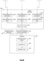
- the calibrating the first and the second sensor further comprises calibrating a third sensor with the first and the second sensor, and the determining one or more parameter of the calibration comprises minimizing an error of point pairs between the first and second sensor, point pairs between the second and third sensor, and point pairs between the third and first sensor.
- the minimizing of the error of the point pairs comprises minimizing a weighted sum of the errors of the point pairs of the sensor pairs.
- the method further comprises validating the a priori calibration, wherein the validating comprises comparing the one or more parameters of the determined calibration with one or more corresponding parameters of an a priori calibration and validating the calibration if a difference between the determined calibration and the a priori calibration is smaller than a predetermined threshold.
- the validating comprises, for each of a plurality of sensors, which comprise the first and the second sensor:
- a second aspect of the invention provides a calibration system for calibrating a first and a second sensor of a vehicle, the calibration unit comprising:
- each detected object is represented with a single point.
- the following can be done: For processing the camera frames, different (state-of-the-art) image processing and/or object detection methods may be used. For this example, let the detected objects be the cars visible on the camera frame. Then, we may use a neural network trained for detecting these objects, providing their positions in image-space.
- the method may be implemented differently when using different sensors: Using a radar device capable of tracking objects, the clustering step may be eliminated, since we get the required positions from the device itself. Using e.g. a lidar instead of the camera, one can cluster its point cloud just like that of the radar.
- the vehicles 122, 124, 126, bounding boxes 132, 134, 136 and center points of the bounding boxes 132, 134, 136 can be identified.
- the crosses 142, 144, 146 in the cars are indicate the centers of the objects detected on the camera frames using a neural network.
- the circles 152, 154, 156 indicate the centers of the clusters detected on the radar frames projected onto the image.
- the centers 142, 144, 146 of the objects detected on the camera frame are not fully aligned with the centers of the clusters detected on the radar frames.
- the filtering is:
- both the data from a first sensor and the data from a second sensor can be filtered and in that case different filtering rules can be applied to the data from the different sensors.
- At least one of the applied filtering methods is based on a position of the data, i.e., the decision which datapoint to keep and which datapoint to filter out is based on a position of the datapoint in the data.
- the a priori calibration may contain significant errors.
- a goal of the presented method includes the elimination of these errors. If no or just minimal error is present, the distances of the point pairs is minimal, thus the result of the calibration will be highly similar to the a priori.
- the method can also be used for the validation of existing calibration parameters.
- the center of its view region shall be selected.
- the perimeter of its view region shall be selected.
- the selected view region depends on the first sensor's view region and the a priori calibration (e.g. one sensor may look forward and the other may look sideways).
- the region is well defined.
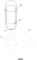
- FIG. 2A is a schematic illustration of a car 200 and the view regions of its two sensors (a radar 210 and a camera 220). Specifically, the radar 210 has a view region 212 and the camera 220 has a view region 222, which partially overlaps with the view region 212 of the radar.
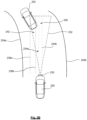
- a left boundary 234a and a right boundary 234b of the base filter region 240 are defined as lines that are parallel to a center line (not shown in FIG. 2B ) that is defined by longitudinal middle of the car. In horizontal direction, these boundaries 234a, 234b have an equal distance to the center line.
- the method's execution may depend on the a priori calibration minimally, provided one of the paired sensors greatly differs from the direction the vehicle travels, while the other's is well aligned with this traveling direction.
- the error of the a priori calibration is realized as an error in the projected filtered region. This dependency on the a priori calibration can be loosened by several methods:
- FIG. 2B is a schematic illustration of the car 200, the view region 234 of a sensor 230 of the car and a base filter area 240 as well as a shifted filter area 242 based on a steering angle of the car.
- the base filter area 240 which corresponds to the filter area when the car is driving straight, has boundaries 234a, 234b.
- the filter region is also shifted to the left, thus obtaining a new filter region 242, with boundaries 236a, 236b that are shifted to the left from the boundaries 234a, 234b of the base filter region.
- the shift of the boundaries is proportional to a steering angle or a sine of the steering angle or another function of the steering angle.
- the width of the shifted filter region may be the same as the width of the base filter region or in other embodiments it may also vary based on a function of the steering angle.
- the car driving in front of the vehicle that carries the sensor is out of the center region as seen on the radar frames, if this region is not offset by the steering angle.
- using the steering angle for modifying the filtered area makes the data collection shorter, while not changing the results' quality.
- the filter region typically only partially overlaps with the view region 232 of the sensor.
- the error metrics between any two sensor pairing may differ. Such decisions are up to the user to decide.
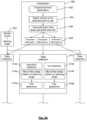
- the base of the validation is the calibration process described above. If the calibration of the sensors gives the same (or nearly the same) extrinsic parameters as the a priori calibration, the a priori calibration is deemed still valid.
- steps 316a, 316b corresponding pairs are identified in the filtered data.
Landscapes
- Engineering & Computer Science (AREA)
- Radar, Positioning & Navigation (AREA)
- Remote Sensing (AREA)
- Physics & Mathematics (AREA)
- General Physics & Mathematics (AREA)
- Computer Networks & Wireless Communication (AREA)
- Computer Vision & Pattern Recognition (AREA)
- Theoretical Computer Science (AREA)
- Electromagnetism (AREA)
- Length Measuring Devices By Optical Means (AREA)
- Image Analysis (AREA)
Priority Applications (6)
| Application Number | Priority Date | Filing Date | Title |
|---|---|---|---|
| EP22180544.3A EP4296711A1 (en) | 2022-06-22 | 2022-06-22 | Automatic extrinsic calibration and calibration validation of different sensor modalities, e.g camera, radar and lidar sensors |
| KR1020257001028A KR20250028355A (ko) | 2022-06-22 | 2023-05-11 | 상이한 센서 모달리티들, 예컨대, 카메라, 레이더 및 라이더 센서들의 자동 외부 교정 및 교정 검증 |
| CN202380046754.8A CN119365790A (zh) | 2022-06-22 | 2023-05-11 | 不同传感器模态例如摄像装置、雷达和激光雷达传感器的自动外部校准和校准验证 |
| US18/875,560 US20250363666A1 (en) | 2022-06-22 | 2023-05-11 | Automatic extrinsic calibration and calibration validation of different sensor modalities, e.g camera, radar and lidar sensors |
| PCT/EP2023/062655 WO2023247109A1 (en) | 2022-06-22 | 2023-05-11 | Automatic extrinsic calibration and calibration validation of different sensor modalities, e.g camera, radar and lidar sensors |
| JP2024573556A JP2025519690A (ja) | 2022-06-22 | 2023-05-11 | さまざまなセンサ・モダリティ、たとえば、カメラ、レーダー、およびライダー・センサの自動的な外部較正および較正検証 |
Applications Claiming Priority (1)
| Application Number | Priority Date | Filing Date | Title |
|---|---|---|---|
| EP22180544.3A EP4296711A1 (en) | 2022-06-22 | 2022-06-22 | Automatic extrinsic calibration and calibration validation of different sensor modalities, e.g camera, radar and lidar sensors |
Publications (1)
| Publication Number | Publication Date |
|---|---|
| EP4296711A1 true EP4296711A1 (en) | 2023-12-27 |
Family
ID=82214435
Family Applications (1)
| Application Number | Title | Priority Date | Filing Date |
|---|---|---|---|
| EP22180544.3A Pending EP4296711A1 (en) | 2022-06-22 | 2022-06-22 | Automatic extrinsic calibration and calibration validation of different sensor modalities, e.g camera, radar and lidar sensors |
Country Status (6)
| Country | Link |
|---|---|
| US (1) | US20250363666A1 (cg-RX-API-DMAC7.html) |
| EP (1) | EP4296711A1 (cg-RX-API-DMAC7.html) |
| JP (1) | JP2025519690A (cg-RX-API-DMAC7.html) |
| KR (1) | KR20250028355A (cg-RX-API-DMAC7.html) |
| CN (1) | CN119365790A (cg-RX-API-DMAC7.html) |
| WO (1) | WO2023247109A1 (cg-RX-API-DMAC7.html) |
Families Citing this family (2)
| Publication number | Priority date | Publication date | Assignee | Title |
|---|---|---|---|---|
| US20250117029A1 (en) * | 2023-10-04 | 2025-04-10 | Nec Laboratories America, Inc. | Automatic multi-modality sensor calibration with near-infrared images |
| CN121686377A (zh) * | 2025-11-28 | 2026-03-17 | 中移(上海)信息通信科技有限公司 | 感知目标融合方法、装置及设备 |
Citations (1)
| Publication number | Priority date | Publication date | Assignee | Title |
|---|---|---|---|---|
| WO2021007152A1 (en) * | 2019-07-09 | 2021-01-14 | Refraction Ai, Inc. | Method and system for autonomous vehicle control |
-
2022
- 2022-06-22 EP EP22180544.3A patent/EP4296711A1/en active Pending
-
2023
- 2023-05-11 US US18/875,560 patent/US20250363666A1/en active Pending
- 2023-05-11 CN CN202380046754.8A patent/CN119365790A/zh active Pending
- 2023-05-11 WO PCT/EP2023/062655 patent/WO2023247109A1/en not_active Ceased
- 2023-05-11 KR KR1020257001028A patent/KR20250028355A/ko active Pending
- 2023-05-11 JP JP2024573556A patent/JP2025519690A/ja active Pending
Patent Citations (1)
| Publication number | Priority date | Publication date | Assignee | Title |
|---|---|---|---|---|
| WO2021007152A1 (en) * | 2019-07-09 | 2021-01-14 | Refraction Ai, Inc. | Method and system for autonomous vehicle control |
Non-Patent Citations (2)
| Title |
|---|
| GUOHANG YAN ET AL: "OpenCalib: A multi-sensor calibration toolbox for autonomous driving", ARXIV.ORG, CORNELL UNIVERSITY LIBRARY, 201 OLIN LIBRARY CORNELL UNIVERSITY ITHACA, NY 14853, 27 May 2022 (2022-05-27), XP091234169 * |
| JIANG JINGJING ET AL: "Line Feature Based Extrinsic Calibration of LiDAR and Camera", 2018 IEEE INTERNATIONAL CONFERENCE ON VEHICULAR ELECTRONICS AND SAFETY (ICVES), IEEE, 12 September 2018 (2018-09-12), pages 1 - 6, XP033439350, [retrieved on 20181031], DOI: 10.1109/ICVES.2018.8519493 * |
Also Published As
| Publication number | Publication date |
|---|---|
| JP2025519690A (ja) | 2025-06-26 |
| KR20250028355A (ko) | 2025-02-28 |
| CN119365790A (zh) | 2025-01-24 |
| US20250363666A1 (en) | 2025-11-27 |
| WO2023247109A1 (en) | 2023-12-28 |
Similar Documents
| Publication | Publication Date | Title |
|---|---|---|
| US11731649B2 (en) | High precision position estimation method through road shape classification-based map matching and autonomous vehicle thereof | |
| US7876926B2 (en) | Lane marker detection and fitting methods | |
| US8050458B2 (en) | Frontal view imaging and control device installed on movable object | |
| US10984555B2 (en) | Object detection device and vehicle | |
| EP3735675A1 (en) | Image annotation | |
| JP3367170B2 (ja) | 障害物検出装置 | |
| CN114549632B (zh) | 车辆定位方法及装置 | |
| US12174301B2 (en) | Online validation of LIDAR-to-LIDAR alignment and LIDAR-to-vehicle alignment | |
| US10984263B2 (en) | Detection and validation of objects from sequential images of a camera by using homographies | |
| US20250363666A1 (en) | Automatic extrinsic calibration and calibration validation of different sensor modalities, e.g camera, radar and lidar sensors | |
| US11281916B2 (en) | Method of tracking objects in a scene | |
| CN112927309A (zh) | 一种车载相机标定方法、装置、车载相机及存储介质 | |
| JP6552448B2 (ja) | 車両位置検出装置、車両位置検出方法及び車両位置検出用コンピュータプログラム | |
| CN109727285B (zh) | 使用边缘图像的位置和姿态确定方法和系统 | |
| US20210326613A1 (en) | Vehicle detection method and device | |
| US10977816B2 (en) | Image processing apparatus, image processing program, and driving assistance system | |
| KR102003387B1 (ko) | 조감도 이미지를 이용한 교통 장애물의 검출 및 거리 측정 방법, 교통 장애물을 검출하고 거리를 측정하는 프로그램을 저장한 컴퓨터 판독가능 기록매체 | |
| JP2018077162A (ja) | 車両位置検出装置、車両位置検出方法及び車両位置検出用コンピュータプログラム | |
| CN117392423A (zh) | 基于激光雷达的目标物的真值数据预测方法、装置及设备 | |
| CN114627264A (zh) | 确定目标方向的方法以及用于追踪目标的方法和装置 | |
| Levinson | Automatic laser calibration, mapping, and localization for autonomous vehicles | |
| WO2022133986A1 (en) | Accuracy estimation method and system | |
| JP2025519690A5 (cg-RX-API-DMAC7.html) | ||
| US20250076880A1 (en) | High-definition mapping | |
| JP5490633B2 (ja) | 車両の進行路推定装置 |
Legal Events
| Date | Code | Title | Description |
|---|---|---|---|
| PUAI | Public reference made under article 153(3) epc to a published international application that has entered the european phase |
Free format text: ORIGINAL CODE: 0009012 |
|
| STAA | Information on the status of an ep patent application or granted ep patent |
Free format text: STATUS: THE APPLICATION HAS BEEN PUBLISHED |
|
| AK | Designated contracting states |
Kind code of ref document: A1 Designated state(s): AL AT BE BG CH CY CZ DE DK EE ES FI FR GB GR HR HU IE IS IT LI LT LU LV MC MK MT NL NO PL PT RO RS SE SI SK SM TR |
|
| STAA | Information on the status of an ep patent application or granted ep patent |
Free format text: STATUS: REQUEST FOR EXAMINATION WAS MADE |
|
| 17P | Request for examination filed |
Effective date: 20240627 |
|
| RBV | Designated contracting states (corrected) |
Designated state(s): AL AT BE BG CH CY CZ DE DK EE ES FI FR GB GR HR HU IE IS IT LI LT LU LV MC MK MT NL NO PL PT RO RS SE SI SK SM TR |
|
| STAA | Information on the status of an ep patent application or granted ep patent |
Free format text: STATUS: EXAMINATION IS IN PROGRESS |
|
| 17Q | First examination report despatched |
Effective date: 20241021 |
|
| GRAP | Despatch of communication of intention to grant a patent |
Free format text: ORIGINAL CODE: EPIDOSNIGR1 |
|
| STAA | Information on the status of an ep patent application or granted ep patent |
Free format text: STATUS: GRANT OF PATENT IS INTENDED |
|
| INTG | Intention to grant announced |
Effective date: 20260331 |
|
| P01 | Opt-out of the competence of the unified patent court (upc) registered |
Free format text: CASE NUMBER: UPC_APP_0015724_4296711/2026 Effective date: 20260515 |
|
| GRAS | Grant fee paid |
Free format text: ORIGINAL CODE: EPIDOSNIGR3 |
|
| GRAA | (expected) grant |
Free format text: ORIGINAL CODE: 0009210 |
|
| STAA | Information on the status of an ep patent application or granted ep patent |
Free format text: STATUS: THE PATENT HAS BEEN GRANTED |