EP4296658A1 - Sample container and measuring method - Google Patents
Sample container and measuring method Download PDFInfo
- Publication number
- EP4296658A1 EP4296658A1 EP23170827.2A EP23170827A EP4296658A1 EP 4296658 A1 EP4296658 A1 EP 4296658A1 EP 23170827 A EP23170827 A EP 23170827A EP 4296658 A1 EP4296658 A1 EP 4296658A1
- Authority
- EP
- European Patent Office
- Prior art keywords
- pressure
- receptacle
- sample
- sample container
- outside
- Prior art date
- Legal status (The legal status is an assumption and is not a legal conclusion. Google has not performed a legal analysis and makes no representation as to the accuracy of the status listed.)
- Granted
Links
Images





Classifications
-
- G—PHYSICS
- G01—MEASURING; TESTING
- G01N—INVESTIGATING OR ANALYSING MATERIALS BY DETERMINING THEIR CHEMICAL OR PHYSICAL PROPERTIES
- G01N23/00—Investigating or analysing materials by the use of wave or particle radiation, e.g. X-rays or neutrons, not covered by groups G01N3/00 – G01N17/00, G01N21/00 or G01N22/00
- G01N23/22—Investigating or analysing materials by the use of wave or particle radiation, e.g. X-rays or neutrons, not covered by groups G01N3/00 – G01N17/00, G01N21/00 or G01N22/00 by measuring secondary emission from the material
- G01N23/2204—Specimen supports therefor; Sample conveying means therefore
-
- G—PHYSICS
- G01—MEASURING; TESTING
- G01N—INVESTIGATING OR ANALYSING MATERIALS BY DETERMINING THEIR CHEMICAL OR PHYSICAL PROPERTIES
- G01N23/00—Investigating or analysing materials by the use of wave or particle radiation, e.g. X-rays or neutrons, not covered by groups G01N3/00 – G01N17/00, G01N21/00 or G01N22/00
- G01N23/22—Investigating or analysing materials by the use of wave or particle radiation, e.g. X-rays or neutrons, not covered by groups G01N3/00 – G01N17/00, G01N21/00 or G01N22/00 by measuring secondary emission from the material
- G01N23/223—Investigating or analysing materials by the use of wave or particle radiation, e.g. X-rays or neutrons, not covered by groups G01N3/00 – G01N17/00, G01N21/00 or G01N22/00 by measuring secondary emission from the material by irradiating the sample with X-rays or gamma-rays and by measuring X-ray fluorescence
Definitions
- the present invention relates to a sample container and a measuring method.
- Patent document 1 JP-A-2001-349852
- sample container associated with the present invention is for use with an X-ray fluorescence (XRF) analyzer and comprises:
- the measuring method comprises the steps of: receiving a liquid sample in the first receptacle; introducing the sample container into a sample chamber of an XRF analyzer; lowering the pressure in the sample chamber such that the sample chamber is placed in a vacuum atmosphere; irradiating the liquid sample received in the sample container with X-rays through the analytical film within the vacuum atmosphere of the sample chamber; and detecting fluorescent X-rays responsively emitted from the liquid sample.
- the pressure in the first receptacle can be adjusted with the pressure adjusting valve. Therefore, in the vacuum atmosphere of the sample chamber, the pressure in the first receptacle can be maintained higher than the pressure at which the liquid sample boils and lower than the pressure at which the analytical film is damaged.
- the use of the sample container permits the XRF analyzer to perform measurements while placing the interior of the sample chamber in a vacuum atmosphere. Consequently, light elements in the liquid sample can be measured without replacing the air within the sample chamber by helium.
- the sample container 100 includes a sample cup 10 (one example of a second receptacle), an analytical film 20 (i.e., film for analytical use), a film supporting member 30, a sealed receptacle 40 (one example of a first receptacle), a pressure adjusting valve 50, and a leak valve 60.
- FIG. 1 shows a state where the sample cup 10 has been mounted to the sealed receptacle 40.
- the liquid sample S to be measured is received in the sample cup 10.
- Examples of the liquid sample S to be measured include foods (such as drinking water), cleaning fluids (such as organic solvents), alcohols (such as ethanol), and oils.
- the sample cup 10 is cylindrical, for example, and has a first opening 12 and a second opening 14.
- the first opening 12 is at the top of the sample cup 10, while the second opening 14 is at the bottom of the sample cup 10.
- the first opening 12 is located inside the sealed receptacle 40, whereas the second opening 14 is located outside the sealed receptacle 40.
- the second opening 14 is closed off by the analytical film 20.
- the analytical film 20 is detachably supported to the sample cup 10 by the film supporting member 30 that is a disklike member and centrally provided with a hole 32 into which the sample cup 10 can be inserted.
- the film supporting member 30 that is a disklike member and centrally provided with a hole 32 into which the sample cup 10 can be inserted.
- the pressure adjusting valve 50 operates such that the pressure difference between the inside and outside of the sealed receptacle 40 within the vacuum atmosphere inside the sample container of the XRF analyzer is equal to a preset pressure.
- the pressure in the sealed receptacle 40 is the pressure inside the space 102 of the receptable 40.
- the pressure outside of the sealed receptacle 40 is the pressure inside the sample chamber.
- the pressure adjusting valve 50 opens if the pressure in the sealed receptacle 40 is greater than the pressure outside the sealed receptacle 40 and, at the same time, the pressure difference between the inside and the outside of the sealed receptacle 40 is greater than the preset pressure.
- the pressure adjusting valve 50 closes either if the pressure inside the sealed receptacle 40 is greater than the pressure outside the sealed receptacle 40 and, at the same time, the pressure difference between the inside and the outside of the sealed receptacle 40 is equal to or less than a preset pressure or if the pressure inside the sealed receptacle 40 is equal to or less than the pressure outside the sealed receptacle 40.
- the preset pressure of the pressure adjusting valve 50 is variable.
- valve body 52 is opened, so that the inside and outside of the sealed receptacle 40 are placed in communication with each other.
- the pressure inside the sealed receptacle 40 drops. If the pressure difference between the inside and outside of the sealed receptacle 40 decreases below a preset level, the force F2 of the spring 54 closing the valve body 52 exceeds the force F4 applied to the valve body 52 due to the pressure difference between the inside and outside of the sealed receptacle 40, thus closing the valve body 52.
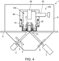
- FIG. 4 illustrates a state where the sample container 100 is placed in the sample chamber 8 of the XRF analyzer 1.
- the XRF analyzer 1 is an apparatus for performing analysis by X-ray fluorescence spectrometry which is a technique of analyzing the liquid sample S by irradiating it with primary X-rays and detecting secondary X-rays produced from the liquid sample S in response to the irradiation.
- the sample chamber 8 When the liquid sample S is measured using the sample container 100, the sample chamber 8 is placed in a vacuum atmosphere at a given pressure. During measurement, the sample chamber 8 is maintained at the given pressure by the vacuum pump. The interior of the sealed receptacle 40 of the sample chamber 8 in the vacuum atmosphere is maintained at a pressure higher than the given pressure inside the sample chamber 8. Within the sample chamber 8 in the vacuum atmosphere, the interior of the sealed receptacle 40 is maintained by the pressure adjusting valve 50 at a pressure which is higher than the pressure at which the liquid sample S boils and lower than the pressure at which the analytical film 20 is damaged.
- the primary X-ray collimator 4 limits the region of the liquid sample S irradiated with the X-rays and thus controls the size of the irradiated region.
- the size of the irradiated region is determined according to the diameter of the sample cup 10, i.e., according to the area of the second opening 14.
- the secondary X-ray collimator 6 limits the usable region of the liquid sample S from which the secondary X-rays are emitted and detected, and permits efficient detection of the secondary X-rays of interest.
- X-rays are emitted from the sample and referred to as secondary X-rays which include fluorescent X-rays and scattered X-rays.
- secondary X-rays which include fluorescent X-rays and scattered X-rays.
- X-rays are emitted by scattering of atoms and electrons and referred to as scattered X-rays.
- inner shell electrons of atoms are excited, leaving inner shell vacancies.
- outer shell electrons fill these vacancies, X-rays known as fluorescent X-rays are released.
- the detector 7 detects secondary X-rays emitted from the liquid sample S and is a semiconductor detector, for example.
- the detector 7 is an energy dispersive X-ray spectrometer (EDS).
- the detector 7 may be a wavelength dispersive X-ray spectrometer (WDS).
- the sample chamber 8 is in a vacuum atmosphere and so light elements in the liquid sample S can be detected with high sensitivity.
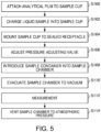
- FIG. 5 is a flowchart illustrating one example of a measuring method using the sample container 100.
- the analytical film 20 is attached to the sample cup 10 (S100).
- the optimum sample cup 10 is selected from plural sample cups of differing diameters according to the type of the liquid sample S to be measured, the element to be measured, the purpose of the measurement, and other factors.
- the optimum analytical film 20 is selected according to the type of the liquid sample S to be measured, the element to be measured, the purpose of the measurement, the diameter of the sample cup 10, and other factors.
- the liquid sample S is charged into the sample cup 10 (S102).
- the sample cup 10 is then mounted into the sealed receptacle 40 (S104).
- the sample cup 10 is inserted into the hole 43 of the base 42 and supported by the sample cup supporting member 46. Consequently, the sample cup 10 can be mounted in the sealed receptacle 40.
- the sample container 100 containing the liquid sample S is admitted into the sample chamber 8 of the XRF analyzer 1 (S108) after opening the cover of the sample chamber in a manner not illustrated.
- the sample chamber 8 is then evacuated and placed in a vacuum atmosphere at a given pressure (S110).
- the sample chamber 8 is pumped down to a given pressure at which X-rays from light elements released from the liquid sample S can be detected by the detector 7.
- the pressure in the sealed receptacle 40 also decreases but the pressure difference between the inner space 102 of the sealed receptacle 40 and the sample chamber 8 outside the sealed receptacle 40 is maintained at a preset pressure by the operation of the pressure adjusting valve 50.
- the interior of the sealed receptacle 40 is maintained at a pressure higher than the pressure at which the liquid sample S boils and lower than the pressure at which the analytical film 20 is damaged.
- the liquid sample S is measured by X-ray fluorescence spectrometry (S112).
- a measurement is started.
- primary X-rays generated by the X-ray tube 2 are directed at the liquid sample S in the sample cup 10 through both the filter 3 and the primary X-ray collimator 4.
- the primary X-rays are transmitted through the analytical film 20 and hit the liquid sample S.
- secondary X-rays are emitted from the liquid sample S, passed through the analytical film 20, and detected by the detector 7 via the secondary X-ray collimator 6.
- the pressure in the sealed receptacle 40 is higher than the pressure at which the liquid sample S boils and so the liquid sample S can be measured without boiling it. Furthermore, the pressure in the sealed receptacle 40 is lower than the pressure at which the analytical film 20 is damaged and, therefore, damage to the film 20 can be prevented. Additionally, the sample chamber 8 can be placed in a vacuum atmosphere. Consequently, attenuation of secondary X-rays emitted from the liquid sample S can be reduced. As a result, light elements, for example, can be measured with high sensitivity.
- the sample chamber 8 is vented to atmospheric pressure (S114). This increases the pressure in the sample chamber 8.
- the pressure in the sealed receptacle 40 is also increased by the operation of the leak valve 60. As a result, damage to the analytical film 20 can be prevented.
- the interior of the sealed receptacle 40 can be placed at atmospheric pressure. Because of the processing steps described so far, the liquid sample S can be measured.
- the sample container 100 is for use with an X-ray fluorescence (XRF) analyzer and includes the sealable receptacle 40, the pressure adjusting valve 50 for adjusting the pressure in the sealed receptacle 40, the sample cup 10 receiving the liquid sample S and having both the first opening 12 and the second opening 14 located inside and outside, respectively, of the sealed receptacle 40, and the analytical film 20 plugging up the second opening 14 and transmitting X-rays.
- XRF X-ray fluorescence
- the pressure in the sealed receptacle 40 can be adjusted with the pressure adjusting valve 50. Therefore, the interior of the sealed receptacle 40 can be maintained at a pressure which is higher than the pressure at which the liquid sample S boils and lower than the pressure at which the analytical film 20 is damaged within the sample chamber 8 in a vacuum atmosphere.
- the use of the sample container 100 makes it possible to perform a measurement while placing the sample chamber 8 of the XRF analyzer 1 in a vacuum atmosphere. In consequence, light elements in the liquid sample S can be measured without replacing the interior environment of the sample chamber 8 by helium.
- the pressure adjusting valve 50 maintains constant the pressure difference between the inside and outside of the sealed receptacle 40 in a vacuum atmosphere. Therefore, in the sample container 100, damage to the analytical film 20 can be prevented.
- the pressure adjusting valve 50 opens, if the pressure in the sealed receptacle 40 is greater than the outside pressure and, at the same time, the pressure difference between the inside and outside of the sealed receptacle 40 is greater than the preset pressure, and closes, if the pressure in the sealed receptacle 40 is greater than the outside pressure and, at the same time, the pressure difference between the inside and outside of the sealed receptacle 40 is equal to or less than the preset pressure which is variable. Therefore, in the sample container 100, the preset pressure can be varied according to both the diameter of the sample cup 10 and the mechanical strength of the analytical film 20 which is determined by the thickness and the material. Accordingly, in the sample container 100, measurements can be performed using sample cups 10 of various diameters and various types of analytical films 20.
- the sample container 100 includes the film supporting member 30 by which the analytical film 20 is detachably supported. Therefore, the analytical film 20 of optimum thickness and optimum material can be used in the sample container 100 according to the type of the liquid sample S to be measured, the element to be measured, the purpose of the measurement, the diameter of the sample cup 10, and other factors.
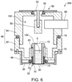
- FIG. 6 is a cross section schematically showing the sample container, 200, associated with the second embodiment.
- those members of the sample container 200 which are similar in function to their respective counterparts of the sample container 100 associated with the first embodiment are indicated by the same reference numerals as in the foregoing figures and a detailed description thereof is omitted.
- the pressure adjusting valve 50 opens and closes the valve body 52 according to the pressure difference between the inside and outside of the sealed receptacle 40 using the spring 54.
- the pressure adjusting valve 50 opens and closes the valve body 52 according to the pressure difference between the inside and outside of the sealed receptacle 40 using a weight 56.
- the weight 56 applies a force to close the valve body 52.
- the pressure adjusting valve 50 operates in the same manner as when using the spring 54.
- the valve body 52 of the pressure adjusting valve 50 is closed by the force of the weight 56. Under this condition, the gap between the valve body 52 and the sealed receptacle 40 is hermetically sealed with the O-ring 58.
- the sample chamber 8 of the XRF analyzer is evacuated to a vacuum, the pressure outside the sealed receptacle 40 drops, the pressure inside the sealed receptacle 40 becomes greater than the pressure outside the sealed receptacle 40, and the pressure difference between the inside and outside of the sealed receptacle 40 exceeds the preset pressure, then the force of the weight 56 to close the valve body 52 is exceeded by the force applied to valve body 52 due to the pressure difference between the inside and outside of the sealed receptacle 40. As a result, the valve body 52 opens, placing the inside and outside of the sealed receptacle 40 in communication with each other.
- valve body 52 As the valve body 52 opens, the pressure in the sealed receptacle 40 drops. If the pressure difference between the inside and outside of the sealed receptacle 40 decreases below the preset pressure, then the force of the weight 56 to close the valve body 52 exceeds the force applied to the valve body 52 due to the pressure difference between the inside and outside of the sealed receptacle 40. As a result, the valve body 52 closes.
- the pressure adjusting valve 50 operates in the same manner as when the valve body 52 is opened and closed according to the pressure difference between the inside and outside of the sealed receptacle 40 using the spring 54.
- the preset pressure can be varied by changing the weight of the weight 56 so as to adjust the force of the weight 56 to close the valve body 52.
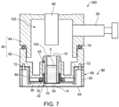
- FIG. 7 is a schematic cross-sectional view of the sample container, 300, associated with the third embodiment.
- FIG. 8 illustrates a state in which the sample container 300 is placed in the sample chamber 8 of the XRF analyzer 1.
- Those members of the sample container 300 which are similar in function to their counterparts of the sample container 100 associated with the first embodiment are indicated by the same reference numerals as in the foregoing figures and a detailed description thereof is omitted.
- the sample container 300 includes a protective receptacle 80.
- the protective receptacle 80 accepts the leaking sample S. Therefore, if the analytical film 20 is damaged, it can be prevented that the liquid sample S splashes and spoils the XRF analyzer 1.
- the protective film 84 transmits X-rays and is made of the same material, for example, as the analytical film 20. As shown in FIG. 8 , primary X-rays are transmitted through the protective film 84 and the analytical film 20 and impinge on the liquid sample S. Secondary X-rays are transmitted through the analytical film 20 and the protective film 84 and detected by the detector 7.
- the protective cup 82 has a ventilation hole 86 forming a gas passageway that interconnects the inside and outside of the protective cup 82. Therefore, as shown in FIG. 8 , if the sample chamber 8 is evacuated to a vacuum and the pressure varies from atmospheric pressure to the vacuum, the inside and outside of the protective cup 82 can be made equal in pressure. Accordingly, damage to the protective film 84 can be prevented.
- the ventilation hole 86 is a through hole formed, for example, in the protective cup 82.
- the protective cup 82 is only required to have a gas passageway interconnecting the inside and outside of the protective cup 82. For example, the gap between the protective cup 82 and the sealed receptacle 40 may be used as the gas passageway that interconnects the inside and outside of the protective cup 82.
- the sample container 400 includes a porous film 90 for producing a pressure difference between the space 102 inside the sealed receptacle 40 and the space 104 inside the sample cup 10.
- the porous film 90 is made of a polypropylene film, unwoven cloth, or the like.
- a film used as a separator in a lithium ion battery may also be used as the porous film 90.
- the porous film 90 is mounted across the first opening 12 of the sample cup 10.
- the first opening 12 of the sample cup 10 is plugged up by the porous film 90 which can partition the space 102 in the sealed receptacle 40 and the space 104 in the sample cup 10 from each other.
- a pressure adjusting liquid L is received in the sealed receptacle 40 and adjusts the pressure in the interior space 102 of the sealed receptacle 40.
- the pressure adjusting liquid L is the same, for example, as the liquid sample S.
- the pressure adjusting liquid L may be different in type from the liquid sample S.
- the pressure adjusting liquid L may be a liquid which has a vapor pressure equal to or higher than that of the liquid sample S at the same temperature.
- the pressure adjusting liquid L has a vapor pressure curve close to that of the liquid sample S.
- FIG. 11 is a flowchart illustrating one example of a measuring method using the sample container 400. In the following description, only differences with the measuring method illustrated in the above-cited FIG. 5 are described; a description of similarities is omitted.
- the analytical film 20 is first attached to the sample cup 10 (S200). Then, the liquid sample S is charged into the sample cup 10 as also shown in FIG. 3 (S202).
- the sample cup 10 is mounted into the sealed receptacle 40 (S204).
- the pressure adjusting liquid L is then put into the sealed receptacle 40 (S205).
- the sealed receptacle 40 has a recess at its bottom. The pressure adjusting liquid L is put into the recess and then the cover 44 is closed.
- the sample container 400 receiving the liquid sample S is introduced into the sample chamber 8 of the XRF analyzer 1 (S408).
- the sample chamber 8 is then evacuated to a vacuum and placed in a vacuum atmosphere at a given pressure (S210). At this pressure, X-rays emanating from light elements in the liquid sample S can be detected by the detector 7.
- the pressure in the sealed receptacle 40 also drops.
- the pressure difference between the interior space 102 of the sealed receptacle 40 and the sample chamber 8 outside the sealed receptacle 40 is maintained at the preset pressure by the operation of the pressure adjusting valve 50.
- the interior of the sealed receptacle 40 is maintained at the pressure higher than the pressure at which the liquid sample S boils and lower than the pressure at which the analytical film 20 is damaged.
- the sample chamber 8 is vented to atmospheric pressure (S214). Because of the processing steps described so far, the liquid sample S can be measured.
- FIG. 12 is a graph showing variations in the pressure in the interior space 102 of the sealed receptacle 40 and variations in the pressure in the interior space 104 of the sample cup 10.
- the pressure in the interior space 102 of the sealed receptacle 40 is indicated by a broken line
- the pressure in the interior space 104 of the sample cup 10 is indicated by a solid line.
- the sample container 400 is made to stay for a long time in the sample chamber 8 that is in a vacuum atmosphere due to a prolonged measurement, gas gradually leaks from clearance gaps in the sealed receptacle 40 and the pressure in the interior space 102 of the sealed receptacle 40 drops. Since the interior space 102 of the sealed receptacle 40 and the interior space 104 of the sample cup 10 are partitioned from each other by the porous film 90, the pressure in the receptacle space 102 drops faster than the pressure in the cup space 104.
- the cup space 104 is maintained at a higher pressure than in the receptacle space 102. This makes it possible to maintain the pressure in the cup space 104 higher than the pressure at which the liquid sample S boils and lower than the pressure at which the analytical film 20 is damaged.
- the pressure adjusting liquid L is identical in vapor pressure to the liquid sample S but the requirement is only that the pressure adjusting liquid L has a vapor pressure equal to or greater than that of the liquid sample S. Consequently, the pressure adjusting liquid L evaporates earlier than the liquid sample S. Hence, the pressure in the cup space 104 can be maintained at a pressure higher than the pressure at which the liquid sample S boils and lower than the pressure at which the analytical film 20 is damaged.
- the porous film 90 is used to produce a differential pressure between the interior space 102 of the sealed receptacle 40 and the interior space 104 of the sample cup 10.
- the differential pressure generator for producing a differential pressure between the receptacle space 102 and the cup space 104 is not restricted to the porous film 90.
- a pressure adjusting valve may be mounted in the first opening 12 of the sample cup 10.
- An orifice may be mounted in the first opening 12.
- the present invention is not restricted to the foregoing embodiments but rather can be implemented in various modified forms.
- the present invention embraces configurations (e.g., configurations identical in function and method) which are substantially identical to the configurations described in any one of the above embodiments.
- the invention embraces configurations which are similar to the configurations described in any one of the above embodiments except that their nonessential portions have been replaced.
- the invention embraces configurations which are similar to the configurations described in any one of the above embodiments except that a well-known technique is added.
Landscapes
- Physics & Mathematics (AREA)
- Health & Medical Sciences (AREA)
- Life Sciences & Earth Sciences (AREA)
- Chemical & Material Sciences (AREA)
- Analytical Chemistry (AREA)
- Biochemistry (AREA)
- General Health & Medical Sciences (AREA)
- General Physics & Mathematics (AREA)
- Immunology (AREA)
- Pathology (AREA)
- Analysing Materials By The Use Of Radiation (AREA)
Abstract
Description
- The present invention relates to a sample container and a measuring method.
- An X-ray fluorescence (XRF) analyzer can perform qualitative, quantitative, and other analyses by irradiating a sample with primary X-rays produced from an X-ray tube and detecting with a detector secondary X-rays responsively emanating from the sample.
- In X-ray fluorescence analysis, when light elements within a liquid are analyzed, the interior of the sample chamber is replaced by helium gas and then a measurement is made. Air absorbs fluorescent X-rays generated from the sample. Especially, air absorbs fluorescent X-rays from light elements released from the sample strongly. Therefore, in general, measurements are performed after a vacuum atmosphere has been created in the sample chamber. However, in a vacuum, liquids evaporate or become frozen and thus light elements in a liquid cannot be measured. Therefore, the air in the sample chamber is replaced by helium gas which less absorbs fluorescent X-rays and then measurements are performed.
- For example,
patent document 1 discloses an XRF analyzer which is designed to measure light elements in a sample and which includes a helium inlet port into an open chamber, a film attach-detach mechanism for attaching and detaching light-element film having a high X-ray transmissivity to and from an open portion of the chamber, and a gas outlet port for expelling gas from inside the chamber. - Patent document 1:
JP-A-2001-349852 - However, in order to replace the air inside the sample chamber with helium gas, a mechanism for replacing the air inside the sample chamber with helium gas is needed as in the XRF analyzer of
patent document 1. Furthermore, a facility for managing high-pressure helium gas is necessary. - One aspect of the sample container associated with the present invention is for use with an X-ray fluorescence (XRF) analyzer and comprises:
- a sealable first receptacle having a pressure therein;
- a pressure adjusting valve for adjusting the pressure in the first receptacle;
- a second receptacle for receiving a liquid sample and having both a first opening and a second opening located inside and outside, respectively of the first receptacle; and
- an analytical film closing off the second opening and transmitting X-rays.
- In this sample container, the pressure in the first receptacle can be adjusted with the pressure adjusting valve and therefore, within the sample chamber in a vacuum atmosphere, the interior of the first receptacle can be maintained at a pressure higher than the pressure at which the liquid sample boils and lower than the pressure at which the analytical film is damaged. The use of the sample container makes it possible to perform measurements using the XRF analyzer while placing the interior of the sample chamber in a vacuum atmosphere. Consequently, the light elements in the liquid sample can be measured without replacing the interior of the sample chamber with helium.
- One aspect of a measuring method associated with the present invention uses a sample container which includes:
- a sealable first receptacle having a pressure therein;
- a pressure adjusting valve for adjusting the pressure in the first receptacle;
- a second receptacle for receiving a liquid sample and having both a first opening and a second opening located inside and outside, respectively of the first receptacle; and
- an analytical film closing off the second opening and transmitting X-rays.
- The measuring method comprises the steps of: receiving a liquid sample in the first receptacle; introducing the sample container into a sample chamber of an XRF analyzer; lowering the pressure in the sample chamber such that the sample chamber is placed in a vacuum atmosphere; irradiating the liquid sample received in the sample container with X-rays through the analytical film within the vacuum atmosphere of the sample chamber; and detecting fluorescent X-rays responsively emitted from the liquid sample.
- In this measuring method, the pressure in the first receptacle can be adjusted with the pressure adjusting valve. Therefore, in the vacuum atmosphere of the sample chamber, the pressure in the first receptacle can be maintained higher than the pressure at which the liquid sample boils and lower than the pressure at which the analytical film is damaged. Thus, the use of the sample container permits the XRF analyzer to perform measurements while placing the interior of the sample chamber in a vacuum atmosphere. Consequently, light elements in the liquid sample can be measured without replacing the air within the sample chamber by helium.
-
-
FIG. 1 is a schematic vertical cross-sectional view of a sample container associated with a first embodiment of the present invention. -
FIG. 2 illustrates a pressure adjusting valve. -
FIG. 3 shows cross sections illustrating a method of charging a liquid sample into a sample cup. -
FIG. 4 is a schematic diagram illustrating an operational state where the sample container ofFIG. 1 has been placed in the sample chamber of an XRF analyzer. -
FIG. 5 is a flowchart illustrating one example of a measuring method using the sample container ofFIG. 1 . -
FIG. 6 is a schematic cross-sectional view of a sample container associated with a second embodiment. -
FIG. 7 is a schematic cross-sectional view of a sample container associated with a third embodiment. -
FIG. 8 is a diagram illustrating an operational state where the sample container ofFIG. 7 has been placed in the sample chamber of an XRF analyzer. -
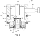
FIG. 9 is a schematic cross-sectional view of a sample container associated with a fourth embodiment. -
FIG. 10 is a diagram illustrating an operational state where the sample container ofFIG. 9 has been placed in the sample chamber of an XRF analyzer. -
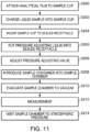
FIG. 11 is a flowchart illustrating one example of a measuring method using the sample container ofFIG. 9 . -
FIG. 12 is a graph showing variations in the pressure within the interior space of a sealed receptacle and variations in the pressure within the interior space of a sample cup. - The preferred embodiments of the present invention are hereinafter described in detail with reference to the drawings. It is to be understood that the embodiments provided below do not unduly restrict the scope and content of the present invention delineated by the appended claims and that not all the configurations described below are essential constituent components of the invention.
- A sample container associated with a first embodiment of the present invention is first described by referring to
FIG. 1 , which schematically shows this sample container, 100. Thesample container 100 is for use with an X-ray fluorescence (XRF) analyzer and permits a liquid sample S to be measured in a sample container that is in a vacuum atmosphere. - As shown in
FIG. 1 , thesample container 100 includes a sample cup 10 (one example of a second receptacle), an analytical film 20 (i.e., film for analytical use), afilm supporting member 30, a sealed receptacle 40 (one example of a first receptacle), apressure adjusting valve 50, and aleak valve 60.FIG. 1 shows a state where thesample cup 10 has been mounted to the sealedreceptacle 40. - The liquid sample S to be measured is received in the
sample cup 10. Examples of the liquid sample S to be measured include foods (such as drinking water), cleaning fluids (such as organic solvents), alcohols (such as ethanol), and oils. - The
sample cup 10 is cylindrical, for example, and has afirst opening 12 and asecond opening 14. Thefirst opening 12 is at the top of thesample cup 10, while thesecond opening 14 is at the bottom of thesample cup 10. When thesample cup 10 has been mounted to the sealedreceptacle 40, thefirst opening 12 is located inside thesealed receptacle 40, whereas thesecond opening 14 is located outside thesealed receptacle 40. Thesecond opening 14 is closed off by theanalytical film 20. - In the
sample container 100, plural kinds of sample cups of different diameters can be used as thesample cup 10. The region irradiated with the primary X-rays can be increased in area by increasing the diameter of thesample cup 10 so as to increase the area of thesecond opening 14, in which case, however, theanalytical film 20 tends to be damaged more easily due to the pressure difference between the inside and outside of the sealedreceptacle 40. In thesample container 100, theoptimum sample cup 10 can be selected from plural kinds of sample cups of different diameters according to the type of the liquid sample S to be measured, the element to be measured, the purpose of the measurement, and other factors. - The
analytical film 20 transmits X-rays and is an organic film as made of Prolene or Mylar. A Prolene film used as theanalytical film 20 has a thickness of about 4 µm, for example. A Mylar film used as theanalytical film 20 has a thickness of about 1.5 µm, for example. The thickness or material of theanalytical film 20 can be varied according to the type of the liquid sample S to be measured, the element to be measured, the purpose of the measurement, the diameter of thesample cup 10, or other factor. - The
analytical film 20 is detachably supported to thesample cup 10 by thefilm supporting member 30 that is a disklike member and centrally provided with ahole 32 into which thesample cup 10 can be inserted. When theanalytical film 20 and thesample cup 10 are inserted into thehole 32 of thefilm supporting member 30, thesample cup 10 and thefilm supporting member 30 are secured while thesecond opening 14 of thesample cup 10 is covered with theanalytical film 20. - The sealed
receptacle 40 is internally sealable and includes abase 42, acover 44, and a samplecup supporting member 46. Thebase 42 is provided with ahole 43 into which thesample cup 10 can be inserted. The samplecup supporting member 46 for supporting thesample cup 10 is mounted to thebase 42. In the illustrated example, the disklikefilm supporting member 30 is supported by the samplecup supporting member 46, whereby thesample cup 10 integrally coupled to thefilm supporting member 30 is secured to the sealedreceptacle 40. The gap between thesample cup 10 coupled to thefilm supporting member 30 and thebase 42 is hermetically sealed with an O-ring 70. The samplecup supporting member 46 is secured to the base 42 withscrews 72. - The
pressure adjusting valve 50 and theleak valve 60 are mounted to thecover 44. In the sample chamber of the XRF analyzer which is in a vacuum atmosphere, the interior of the sealedreceptacle 40 is maintained at a constant pressure, for example, between 600 Pa and atmospheric pressure, by thepressure adjusting valve 50. - The gap between the base 42 and the
cover 44 is hermetically sealed by an O-ring 74. Thebase 42 and thecover 44 together form aspace 102 in which thefirst opening 12 of thesample cup 10 is placed. Therefore, the pressure in aspace 104 within thesample cup 10 is equal to that in thespace 102 within the sealedreceptacle 40. - The
pressure adjusting valve 50 operates such that the pressure difference between the inside and outside of the sealedreceptacle 40 within the vacuum atmosphere inside the sample container of the XRF analyzer is equal to a preset pressure. The pressure in the sealedreceptacle 40 is the pressure inside thespace 102 of thereceptable 40. The pressure outside of the sealedreceptacle 40 is the pressure inside the sample chamber. - The
pressure adjusting valve 50 opens if the pressure in the sealedreceptacle 40 is greater than the pressure outside the sealedreceptacle 40 and, at the same time, the pressure difference between the inside and the outside of the sealedreceptacle 40 is greater than the preset pressure. Thepressure adjusting valve 50 closes either if the pressure inside the sealedreceptacle 40 is greater than the pressure outside the sealedreceptacle 40 and, at the same time, the pressure difference between the inside and the outside of the sealedreceptacle 40 is equal to or less than a preset pressure or if the pressure inside the sealedreceptacle 40 is equal to or less than the pressure outside the sealedreceptacle 40. The preset pressure of thepressure adjusting valve 50 is variable. -
FIG. 2 illustrates thepressure adjusting valve 50 which includes avalve body 52 and aspring 54. Thepressure adjusting valve 50 adjusts the pressure in the sealedreceptacle 40 using thespring 54. - If both inside and outside of the sealed
receptacle 40 are at atmospheric pressure, thevalve body 52 of thepressure adjusting valve 50 is closed by a force F2 of thespring 54. If the sample chamber of the XRF analyzer is evacuated to a vacuum such that the pressure outside the sealedreceptacle 40 drops, the pressure inside the sealedreceptacle 40 becomes greater than the pressure outside the sealedreceptacle 40, and the pressure difference between the inside and outside of the sealedreceptacle 40 exceeds the preset pressure, then the force F2 of thespring 54 that closes thevalve body 52 is exceeded by a force F4 applied to thevalve body 52 due to the pressure difference between the inside and outside of the sealedreceptacle 40. In consequence, thevalve body 52 is opened, so that the inside and outside of the sealedreceptacle 40 are placed in communication with each other. As a result, the pressure inside the sealedreceptacle 40 drops. If the pressure difference between the inside and outside of the sealedreceptacle 40 decreases below a preset level, the force F2 of thespring 54 closing thevalve body 52 exceeds the force F4 applied to thevalve body 52 due to the pressure difference between the inside and outside of the sealedreceptacle 40, thus closing thevalve body 52. - The pressure in the
inside space 102 of the sealedreceptacle 40 can be maintained constant by opening or closing thevalve body 52 according to the pressure difference between the inside and outside of the sealedreceptacle 40 in this way. Furthermore, the preset pressure can be varied by varying the length of thespring 54 so as to adjust the force F2 of thespring 54 closing thevalve body 52. - If the pressure inside the sealed
receptacle 40 is equal to or less than the pressure outside the sealedreceptacle 40 in a manner not illustrated, the force F4 applied to thevalve body 52 due to the pressure difference between the inside and outside of the sealedreceptacle 40 acts to close thevalve body 52. Consequently, thevalve body 52 is closed. - The
leak valve 60 is used to return the interior of the sealedreceptacle 40 to atmospheric pressure. Theleak valve 60 opens, for example, if the pressure outside the sealedreceptacle 40 is greater than the pressure in the sealedreceptacle 40. Theleak valve 60 closes, for example, if the pressure outside the sealedreceptacle 40 is equal to or less than the pressure in the sealedreceptacle 40. Theleak valve 60 opens and closes its valve body according to the pressure difference between the inside and outside of the sealedreceptacle 40 using a spring in the same manner, for example, as thepressure adjusting valve 50. -
FIG. 3 illustrates a method of charging the liquid sample S into thesample cup 10. First, thesecond opening 14 of thesample cup 10 is covered by theanalytical film 20. Under this condition, thesample cup 10 is inserted into thecentral hole 32 of thefilm supporting member 30. Consequently, thesample cup 10 is secured to thefilm supporting member 30. At this time, theanalytical film 20 is squeezed in between thesample cup 10 and thefilm supporting member 30. Thefilm 20 is fixedly stretched across thesecond opening 14. As a result, thesample cup 10 and thefilm supporting member 30 are integrally coupled together. Theanalytical film 20 can plug up thesecond opening 14. - Then, the liquid sample S is poured through the
first opening 12 of thesample cup 10, thus charging the liquid sample S into thesample cup 10. Thesample cup 10 charged with the liquid sample S in this way is loaded into the sealedreceptacle 40 as shown inFIG. 1 . Alternatively, the liquid sample S may be charged into thesample cup 10 after thecup 10 is loaded into the sealedreceptacle 40 in a manner not illustrated. 1.2. X-Ray Fluorescence (XRF) Analyzer -
FIG. 4 illustrates a state where thesample container 100 is placed in thesample chamber 8 of theXRF analyzer 1. TheXRF analyzer 1 is an apparatus for performing analysis by X-ray fluorescence spectrometry which is a technique of analyzing the liquid sample S by irradiating it with primary X-rays and detecting secondary X-rays produced from the liquid sample S in response to the irradiation. - As shown in
FIG. 4 , theXRF analyzer 1 includes thesample container 100, anX-ray tube 2, afilter 3, aprimary X-ray collimator 4, asupport plate 5, asecondary X-ray collimator 6, and adetector 7. As shown, thesample container 100 is received in thesample chamber 8 of theXRF analyzer 1. Received in thesample chamber 8 are thefilter 3,primary X-ray collimator 4,support plate 5, andsecondary X-ray collimator 6, for example. Alternatively, theX-ray tube 2 and thedetector 7 may also be received in thesample chamber 8. TheXRF analyzer 1 is equipped with a vacuum pump (not shown) for evacuating thesample chamber 8 to a vacuum. - When the liquid sample S is measured using the
sample container 100, thesample chamber 8 is placed in a vacuum atmosphere at a given pressure. During measurement, thesample chamber 8 is maintained at the given pressure by the vacuum pump. The interior of the sealedreceptacle 40 of thesample chamber 8 in the vacuum atmosphere is maintained at a pressure higher than the given pressure inside thesample chamber 8. Within thesample chamber 8 in the vacuum atmosphere, the interior of the sealedreceptacle 40 is maintained by thepressure adjusting valve 50 at a pressure which is higher than the pressure at which the liquid sample S boils and lower than the pressure at which theanalytical film 20 is damaged. - The
X-ray tube 2 produces primary X-rays. Voltage and current applied to theX-ray tube 2 are set according to the material of the liquid sample S and the element to be analyzed. Thefilter 3 passes the X-rays generated by theX-ray tube 2. By directing X-rays at the liquid sample S through thefilter 3, parts of continuous X-rays and characteristic X-rays can be absorbed into thefilter 3 and their components can be filtered out. Consequently, the peak to background ratio or other characteristic can be improved. TheXRF analyzer 1 hasplural filters 3 which differ in attenuation band. One used for measurement is selected from theplural filters 3 according to the element to be measured. - The
primary X-ray collimator 4 limits the region of the liquid sample S irradiated with the X-rays and thus controls the size of the irradiated region. The size of the irradiated region is determined according to the diameter of thesample cup 10, i.e., according to the area of thesecond opening 14. - The
support plate 5 mechanically supports thesample container 100 and is provided with an opening through which primary X-rays are directed at theanalytical film 20 of thesample container 100. The primary X-rays pass through theanalytical film 20 and impinge on the liquid sample S. In response, secondary X-rays are emitted from the liquid sample S, are transmitted through theanalytical film 20, and are released through the opening of thesupport plate 5. - The
secondary X-ray collimator 6 limits the usable region of the liquid sample S from which the secondary X-rays are emitted and detected, and permits efficient detection of the secondary X-rays of interest. When a sample is irradiated with primary X-rays, X-rays are emitted from the sample and referred to as secondary X-rays which include fluorescent X-rays and scattered X-rays. When a sample is irradiated with primary X-rays, X-rays are emitted by scattering of atoms and electrons and referred to as scattered X-rays. When a sample is irradiated with primary X-rays, inner shell electrons of atoms are excited, leaving inner shell vacancies. When outer shell electrons fill these vacancies, X-rays known as fluorescent X-rays are released. - The
detector 7 detects secondary X-rays emitted from the liquid sample S and is a semiconductor detector, for example. As an example, thedetector 7 is an energy dispersive X-ray spectrometer (EDS). Alternatively, thedetector 7 may be a wavelength dispersive X-ray spectrometer (WDS). - In the
XRF analyzer 1, thesample chamber 8 is in a vacuum atmosphere and so light elements in the liquid sample S can be detected with high sensitivity. 1.3. Measuring Method -
FIG. 5 is a flowchart illustrating one example of a measuring method using thesample container 100. First, as shown inFIG. 3 , theanalytical film 20 is attached to the sample cup 10 (S100). For example, theoptimum sample cup 10 is selected from plural sample cups of differing diameters according to the type of the liquid sample S to be measured, the element to be measured, the purpose of the measurement, and other factors. Then, the optimumanalytical film 20 is selected according to the type of the liquid sample S to be measured, the element to be measured, the purpose of the measurement, the diameter of thesample cup 10, and other factors. - Then, the
analytical film 20 is attached onto thesample cup 10 by inserting thesample cup 10 whosesecond opening 14 is covered by theanalytical film 20 into thehole 32 of thefilm supporting member 30. Consequently, thesample cup 10 and thefilm supporting member 30 are coupled together integrally, and thesecond opening 14 is covered by theanalytical film 20. - Then, the liquid sample S is charged into the sample cup 10 (S102). As shown in
FIG. 1 , thesample cup 10 is then mounted into the sealed receptacle 40 (S104). Thesample cup 10 is inserted into thehole 43 of thebase 42 and supported by the samplecup supporting member 46. Consequently, thesample cup 10 can be mounted in the sealedreceptacle 40. - The
pressure adjusting valve 50 is then adjusted (S106). In this example, a preset pressure for thepressure adjusting valve 50 is determined such that the pressure in the sealedreceptacle 40 within thesample chamber 8 in the vacuum atmosphere at a given pressure is higher than the pressure at which the liquid sample S boils and lower than the pressure at which theanalytical film 20 is damaged. Accordingly, the preset pressure is determined according to the vapor pressure of the liquid sample S, the diameter of the sample cup 10 (or the area of the second opening 14), the pressure in thesample chamber 8, and other factors. - Then, as shown in
FIG. 4 , thesample container 100 containing the liquid sample S is admitted into thesample chamber 8 of the XRF analyzer 1 (S108) after opening the cover of the sample chamber in a manner not illustrated. - The
sample chamber 8 is then evacuated and placed in a vacuum atmosphere at a given pressure (S110). Thesample chamber 8 is pumped down to a given pressure at which X-rays from light elements released from the liquid sample S can be detected by thedetector 7. As the pressure in thesample chamber 8 drops, the pressure in the sealedreceptacle 40 also decreases but the pressure difference between theinner space 102 of the sealedreceptacle 40 and thesample chamber 8 outside the sealedreceptacle 40 is maintained at a preset pressure by the operation of thepressure adjusting valve 50. The interior of the sealedreceptacle 40 is maintained at a pressure higher than the pressure at which the liquid sample S boils and lower than the pressure at which theanalytical film 20 is damaged. Then, the liquid sample S is measured by X-ray fluorescence spectrometry (S112). - If the pressure in the
sample chamber 8 reaches a preset given pressure and becomes constant, a measurement is started. In particular, primary X-rays generated by theX-ray tube 2 are directed at the liquid sample S in thesample cup 10 through both thefilter 3 and theprimary X-ray collimator 4. The primary X-rays are transmitted through theanalytical film 20 and hit the liquid sample S. In response, secondary X-rays are emitted from the liquid sample S, passed through theanalytical film 20, and detected by thedetector 7 via thesecondary X-ray collimator 6. - As described previously, the pressure in the sealed
receptacle 40 is higher than the pressure at which the liquid sample S boils and so the liquid sample S can be measured without boiling it. Furthermore, the pressure in the sealedreceptacle 40 is lower than the pressure at which theanalytical film 20 is damaged and, therefore, damage to thefilm 20 can be prevented. Additionally, thesample chamber 8 can be placed in a vacuum atmosphere. Consequently, attenuation of secondary X-rays emitted from the liquid sample S can be reduced. As a result, light elements, for example, can be measured with high sensitivity. - After the end of the measurement, the
sample chamber 8 is vented to atmospheric pressure (S114). This increases the pressure in thesample chamber 8. The pressure in the sealedreceptacle 40 is also increased by the operation of theleak valve 60. As a result, damage to theanalytical film 20 can be prevented. The interior of the sealedreceptacle 40 can be placed at atmospheric pressure. Because of the processing steps described so far, the liquid sample S can be measured. - The
sample container 100 is for use with an X-ray fluorescence (XRF) analyzer and includes thesealable receptacle 40, thepressure adjusting valve 50 for adjusting the pressure in the sealedreceptacle 40, thesample cup 10 receiving the liquid sample S and having both thefirst opening 12 and thesecond opening 14 located inside and outside, respectively, of the sealedreceptacle 40, and theanalytical film 20 plugging up thesecond opening 14 and transmitting X-rays. - In the
sample container 100, the pressure in the sealedreceptacle 40 can be adjusted with thepressure adjusting valve 50. Therefore, the interior of the sealedreceptacle 40 can be maintained at a pressure which is higher than the pressure at which the liquid sample S boils and lower than the pressure at which theanalytical film 20 is damaged within thesample chamber 8 in a vacuum atmosphere. Thus, the use of thesample container 100 makes it possible to perform a measurement while placing thesample chamber 8 of theXRF analyzer 1 in a vacuum atmosphere. In consequence, light elements in the liquid sample S can be measured without replacing the interior environment of thesample chamber 8 by helium. - In the
sample container 100, thepressure adjusting valve 50 maintains constant the pressure difference between the inside and outside of the sealedreceptacle 40 in a vacuum atmosphere. Therefore, in thesample container 100, damage to theanalytical film 20 can be prevented. - In the
sample container 100, thepressure adjusting valve 50 opens, if the pressure in the sealedreceptacle 40 is greater than the outside pressure and, at the same time, the pressure difference between the inside and outside of the sealedreceptacle 40 is greater than the preset pressure, and closes, if the pressure in the sealedreceptacle 40 is greater than the outside pressure and, at the same time, the pressure difference between the inside and outside of the sealedreceptacle 40 is equal to or less than the preset pressure which is variable. Therefore, in thesample container 100, the preset pressure can be varied according to both the diameter of thesample cup 10 and the mechanical strength of theanalytical film 20 which is determined by the thickness and the material. Accordingly, in thesample container 100, measurements can be performed usingsample cups 10 of various diameters and various types ofanalytical films 20. - The
sample container 100 includes thefilm supporting member 30 by which theanalytical film 20 is detachably supported. Therefore, theanalytical film 20 of optimum thickness and optimum material can be used in thesample container 100 according to the type of the liquid sample S to be measured, the element to be measured, the purpose of the measurement, the diameter of thesample cup 10, and other factors. - A sample container associated with a second embodiment is next described by referring to
FIG. 6 , which is a cross section schematically showing the sample container, 200, associated with the second embodiment. In the following description, those members of thesample container 200 which are similar in function to their respective counterparts of thesample container 100 associated with the first embodiment are indicated by the same reference numerals as in the foregoing figures and a detailed description thereof is omitted. - In the above-stated
sample container 100 ofFIG. 1 , thepressure adjusting valve 50 opens and closes thevalve body 52 according to the pressure difference between the inside and outside of the sealedreceptacle 40 using thespring 54. - In contrast, in the
sample container 200, thepressure adjusting valve 50 opens and closes thevalve body 52 according to the pressure difference between the inside and outside of the sealedreceptacle 40 using aweight 56. In the example shown inFIG. 6 , theweight 56 applies a force to close thevalve body 52. When using theweight 56, thepressure adjusting valve 50 operates in the same manner as when using thespring 54. - For example, when both the inside and outside of the sealed
receptacle 40 are at atmospheric pressure, thevalve body 52 of thepressure adjusting valve 50 is closed by the force of theweight 56. Under this condition, the gap between thevalve body 52 and the sealedreceptacle 40 is hermetically sealed with the O-ring 58. - If the
sample chamber 8 of the XRF analyzer is evacuated to a vacuum, the pressure outside the sealedreceptacle 40 drops, the pressure inside the sealedreceptacle 40 becomes greater than the pressure outside the sealedreceptacle 40, and the pressure difference between the inside and outside of the sealedreceptacle 40 exceeds the preset pressure, then the force of theweight 56 to close thevalve body 52 is exceeded by the force applied tovalve body 52 due to the pressure difference between the inside and outside of the sealedreceptacle 40. As a result, thevalve body 52 opens, placing the inside and outside of the sealedreceptacle 40 in communication with each other. - As the
valve body 52 opens, the pressure in the sealedreceptacle 40 drops. If the pressure difference between the inside and outside of the sealedreceptacle 40 decreases below the preset pressure, then the force of theweight 56 to close thevalve body 52 exceeds the force applied to thevalve body 52 due to the pressure difference between the inside and outside of the sealedreceptacle 40. As a result, thevalve body 52 closes. - In this way, when the
valve body 52 is opened and closed using theweight 56 according to the pressure difference between the inside and outside of the sealedreceptacle 40, thepressure adjusting valve 50 operates in the same manner as when thevalve body 52 is opened and closed according to the pressure difference between the inside and outside of the sealedreceptacle 40 using thespring 54. The preset pressure can be varied by changing the weight of theweight 56 so as to adjust the force of theweight 56 to close thevalve body 52. - The configuration of the
pressure adjusting valve 50 is not restricted to the examples ofFIGS. 1 and6 . There is no restriction on the configuration as long as the pressure inside the sealedreceptacle 40 can be adjusted. - A sample container associated with a third embodiment is next described by referring to
FIGS. 7 and8 .FIG. 7 is a schematic cross-sectional view of the sample container, 300, associated with the third embodiment.FIG. 8 illustrates a state in which thesample container 300 is placed in thesample chamber 8 of theXRF analyzer 1. Those members of thesample container 300 which are similar in function to their counterparts of thesample container 100 associated with the first embodiment are indicated by the same reference numerals as in the foregoing figures and a detailed description thereof is omitted. - As shown in
FIG. 7 , thesample container 300 includes aprotective receptacle 80. In thesample container 300, if theanalytical film 20 is damaged and the liquid sample S leaks out, theprotective receptacle 80 accepts the leaking sample S. Therefore, if theanalytical film 20 is damaged, it can be prevented that the liquid sample S splashes and spoils theXRF analyzer 1. - The
protective receptacle 80 is secured to the sealedreceptacle 40 and includes a cylindricalprotective cup 82 and aprotective film 84. Theprotective cup 82 has an opening at its bottom, the opening being plugged up by theprotective film 84. Thesecond opening 14 of thesample cup 10 that is plugged up by theanalytical film 20 is located in theprotective cup 82. Therefore, if theanalytical film 20 is damaged and the liquid sample S leaks out, it can be accepted by theprotective receptacle 80. - The
protective film 84 transmits X-rays and is made of the same material, for example, as theanalytical film 20. As shown inFIG. 8 , primary X-rays are transmitted through theprotective film 84 and theanalytical film 20 and impinge on the liquid sample S. Secondary X-rays are transmitted through theanalytical film 20 and theprotective film 84 and detected by thedetector 7. - The
protective cup 82 has aventilation hole 86 forming a gas passageway that interconnects the inside and outside of theprotective cup 82. Therefore, as shown inFIG. 8 , if thesample chamber 8 is evacuated to a vacuum and the pressure varies from atmospheric pressure to the vacuum, the inside and outside of theprotective cup 82 can be made equal in pressure. Accordingly, damage to theprotective film 84 can be prevented. Theventilation hole 86 is a through hole formed, for example, in theprotective cup 82. Theprotective cup 82 is only required to have a gas passageway interconnecting the inside and outside of theprotective cup 82. For example, the gap between theprotective cup 82 and the sealedreceptacle 40 may be used as the gas passageway that interconnects the inside and outside of theprotective cup 82. - A sample container associated with a fourth embodiment is next described by referring to
FIGS. 9 and10 .FIG. 9 is a schematic cross-sectional view of the sample container, 400, associated with the fourth embodiment.FIG. 8 illustrates a state in which thesample container 400 is placed in thesample chamber 8 of theXRF analyzer 1. In the following description, those members of thesample container 400 which are similar in function to their respective counterparts of thesample container 100 associated with the first embodiment are indicated by the same reference numerals as in the foregoing figures and a detailed description thereof is omitted. - As shown in
FIG. 9 , thesample container 400 includes aporous film 90 for producing a pressure difference between thespace 102 inside the sealedreceptacle 40 and thespace 104 inside thesample cup 10. Theporous film 90 is made of a polypropylene film, unwoven cloth, or the like. A film used as a separator in a lithium ion battery may also be used as theporous film 90. - The
porous film 90 is mounted across thefirst opening 12 of thesample cup 10. In the illustrated example, thefirst opening 12 of thesample cup 10 is plugged up by theporous film 90 which can partition thespace 102 in the sealedreceptacle 40 and thespace 104 in thesample cup 10 from each other. - A pressure adjusting liquid L is received in the sealed
receptacle 40 and adjusts the pressure in theinterior space 102 of the sealedreceptacle 40. The pressure adjusting liquid L is the same, for example, as the liquid sample S. Alternatively, the pressure adjusting liquid L may be different in type from the liquid sample S. For example, the pressure adjusting liquid L may be a liquid which has a vapor pressure equal to or higher than that of the liquid sample S at the same temperature. Preferably, the pressure adjusting liquid L has a vapor pressure curve close to that of the liquid sample S. -
FIG. 11 is a flowchart illustrating one example of a measuring method using thesample container 400. In the following description, only differences with the measuring method illustrated in the above-citedFIG. 5 are described; a description of similarities is omitted. - As shown in
FIG. 3 , theanalytical film 20 is first attached to the sample cup 10 (S200). Then, the liquid sample S is charged into thesample cup 10 as also shown inFIG. 3 (S202). - Then, as shown in
FIG. 9 , thesample cup 10 is mounted into the sealed receptacle 40 (S204). The pressure adjusting liquid L is then put into the sealed receptacle 40 (S205). The sealedreceptacle 40 has a recess at its bottom. The pressure adjusting liquid L is put into the recess and then thecover 44 is closed. - Then, the
pressure adjusting valve 50 is adjusted (S206). The preset pressure is so determined that, in thesample chamber 8 placed in a vacuum atmosphere at a given pressure, the pressure in the sealedreceptacle 40 is higher than the pressure at which the liquid sample S boils and lower than the pressure at which theanalytical film 20 is damaged. There is no restriction on the order in which the steps S200, S202, S204, S205, and S206 are carried out. - Then, as shown in
FIG. 10 , thesample container 400 receiving the liquid sample S is introduced into thesample chamber 8 of the XRF analyzer 1 (S408). Thesample chamber 8 is then evacuated to a vacuum and placed in a vacuum atmosphere at a given pressure (S210). At this pressure, X-rays emanating from light elements in the liquid sample S can be detected by thedetector 7. At this time, as the pressure in thesample chamber 8 drops, the pressure in the sealedreceptacle 40 also drops. The pressure difference between theinterior space 102 of the sealedreceptacle 40 and thesample chamber 8 outside the sealedreceptacle 40 is maintained at the preset pressure by the operation of thepressure adjusting valve 50. The interior of the sealedreceptacle 40 is maintained at the pressure higher than the pressure at which the liquid sample S boils and lower than the pressure at which theanalytical film 20 is damaged. - Then, the liquid sample S is measured by X-ray fluorescence spectrometry (S212). When the pressure in the
sample chamber 8 reaches the preset, given pressure and becomes constant, the measurement is started. - If the
sample container 400 is caused to reside in thesample chamber 8 in a vacuum atmosphere for a long time by a prolonged measurement, thesample container 400 can suppress the drop of the pressure inside thesample cup 10 charged with the liquid sample S. That is, in thesample container 400, if the measurement is performed for a long time, the pressure inside thesample cup 10 can be maintained higher than the pressure at which the liquid sample S boils and lower than the pressure at which theanalytical film 20 is damaged, for the reason described later. - After the end of the measurement, the
sample chamber 8 is vented to atmospheric pressure (S214). Because of the processing steps described so far, the liquid sample S can be measured. -
FIG. 12 is a graph showing variations in the pressure in theinterior space 102 of the sealedreceptacle 40 and variations in the pressure in theinterior space 104 of thesample cup 10. InFIG. 12 , the pressure in theinterior space 102 of the sealedreceptacle 40 is indicated by a broken line, while the pressure in theinterior space 104 of thesample cup 10 is indicated by a solid line. - Vacuum pumping of the
sample chamber 8 is initiated at instant T1 and thesample chamber 8 reaches a given pressure at instant T2. At this time, the pressure in theinterior space 102 of the sealedreceptacle 40 is maintained at pressure P0 (pressure level indicated by the higher dotted line) higher than the pressure at which the liquid sample S boils and lower than the pressure at which theanalytical film 20 is damaged. - If the
sample container 400 is made to stay for a long time in thesample chamber 8 that is in a vacuum atmosphere due to a prolonged measurement, gas gradually leaks from clearance gaps in the sealedreceptacle 40 and the pressure in theinterior space 102 of the sealedreceptacle 40 drops. Since theinterior space 102 of the sealedreceptacle 40 and theinterior space 104 of thesample cup 10 are partitioned from each other by theporous film 90, the pressure in thereceptacle space 102 drops faster than the pressure in thecup space 104. - The pressure in the
receptacle space 102 drops and, at instant T3, the pressure in thereceptacle space 102 is greater than the vapor pressure P2 (pressure level indicated by the lower dotted line) of the pressure adjusting liquid L. This initiates evaporation of the pressure adjusting liquid L. Because the pressure in thereceptacle space 102 drops faster than the pressure in theinterior space 104 of thesample cup 10, the pressure adjusting liquid L starts to evaporate earlier than the liquid sample S if the vapor pressure of the pressure adjusting liquid L and the vapor pressure of the liquid sample S are equal at the same temperature. - The evaporation of the pressure adjusting liquid L suppresses the pressure in the
receptacle space 102 from decreasing. The pressure rise caused by evaporation of the pressure adjusting liquid L is balanced by the pressure decrease caused by the leakage, whereby the pressure in thereceptacle space 102 can be maintained constant. - Because the
receptacle space 102 andcup space 104 are partitioned from each other by theporous film 90, thecup space 104 is maintained at a higher pressure than in thereceptacle space 102. This makes it possible to maintain the pressure in thecup space 104 higher than the pressure at which the liquid sample S boils and lower than the pressure at which theanalytical film 20 is damaged. - An example has been described in which the pressure adjusting liquid L is identical in vapor pressure to the liquid sample S but the requirement is only that the pressure adjusting liquid L has a vapor pressure equal to or greater than that of the liquid sample S. Consequently, the pressure adjusting liquid L evaporates earlier than the liquid sample S. Hence, the pressure in the
cup space 104 can be maintained at a pressure higher than the pressure at which the liquid sample S boils and lower than the pressure at which theanalytical film 20 is damaged. - The
sample container 400 includes theporous film 90 which is mounted across thefirst opening 12 and which acts to produce a pressure difference between theinterior space 102 of the sealedreceptacle 40 and theinterior space 104 of thesample cup 10. Therefore, by receiving the pressure adjusting liquid L in the sealedreceptacle 40, if thesample container 100 is kept positioned in the vacuum atmosphere of thesample chamber 8 for a long time as described previously, the pressure in thecup space 104 can be maintained at a pressure higher than the pressure at which the liquid sample S boils and lower than the pressure at which theanalytical film 20 is damaged. - In the fourth embodiment described above, the
porous film 90 is used to produce a differential pressure between theinterior space 102 of the sealedreceptacle 40 and theinterior space 104 of thesample cup 10. The differential pressure generator for producing a differential pressure between thereceptacle space 102 and thecup space 104 is not restricted to theporous film 90. For example, a pressure adjusting valve may be mounted in thefirst opening 12 of thesample cup 10. An orifice may be mounted in thefirst opening 12. With a pressure adjusting valve or an orifice, a pressure difference can be created between theinterior space 102 of the sealedreceptacle 40 and theinterior space 104 of thesample cup 10 in the same manner as with theporous film 90. - It is to be understood that the present invention is not restricted to the foregoing embodiments but rather can be implemented in various modified forms. For example, the present invention embraces configurations (e.g., configurations identical in function and method) which are substantially identical to the configurations described in any one of the above embodiments. Furthermore, the invention embraces configurations which are similar to the configurations described in any one of the above embodiments except that their nonessential portions have been replaced. Further, the invention embraces configurations which are similar to the configurations described in any one of the above embodiments except that a well-known technique is added.
Claims (15)
- A sample container for use with an X-ray fluorescence analyzer, comprising:a sealable first receptacle having a pressure therein;a pressure adjusting valve for adjusting the pressure in the first receptacle;a second receptacle for receiving a liquid sample and having both a first opening and a second opening located inside and outside, respectively, of the first receptacle; andan analytical film closing off the second opening and transmitting X-rays.
- A sample container as set forth in claim 1, wherein said pressure adjusting valve maintains constant a pressure difference between the inside and outside of said first receptacle in a vacuum atmosphere.
- A sample container as set forth in claim 1 or 2, wherein said pressure adjusting valve opens if the pressure inside said first receptacle is greater than the pressure outside the first receptacle and, at the same time, a pressure difference between the inside and outside of the first receptacle is greater than a preset pressure and closes if the pressure inside the first receptacle is greater than the pressure outside the first receptacle and, at the same time, the pressure difference between the inside and outside of the first receptacle is equal to or less than the preset pressure that is variable.
- A sample container as set forth in any one of claims 1 to 3, further comprising a differential pressure generator mounted in or across said first opening and operating to produce a pressure difference between an interior space of said first receptacle and an interior space of said second receptacle.
- A sample container as set forth in claim 4, wherein said differential pressure generator is a porous film plugging up said first opening.
- A sample container as set forth in claim 5, wherein a liquid having a vapor pressure equal to or higher than the vapor pressure of said liquid sample is received in said second receptacle.
- A sample container as set forth in any one of claims 1 to 6, further comprising a protective receptacle which covers said analytical film and includes a protective film transmitting X-rays.
- A sample container as set forth in claim 7, wherein said protective receptacle has a gas passageway interconnecting the inside and outside of the protective receptacle.
- A sample container as set forth in any one of claims 1 to 8, further comprising a film supporting member by which said analytical film is detachably supported.
- A measuring method using a sample container including a sealable first receptacle having a pressure therein, a pressure adjusting valve for adjusting the pressure in the first receptacle, a second receptacle for receiving a liquid sample and having both a first opening and a second opening located inside and outside, respectively, of the first receptacle, and an analytical film closing off the second opening and transmitting X-rays, said method comprising the steps of:receiving a liquid sample in said first receptacle;introducing the sample container into a sample chamber of an X-ray fluorescence analyzer;lowering the pressure in the sample chamber such that the sample chamber is placed in a vacuum atmosphere; andirradiating the liquid sample received in the sample container with X-rays through the analytical film within the vacuum atmosphere of the sample chamber and detecting fluorescent X-rays responsively emitted from the liquid sample.
- A measuring method as set forth in claim 10, wherein said pressure adjusting valve makes constant the pressure difference between the inside and outside of said first receptacle in the vacuum atmosphere.
- A measuring method as set forth in claim 10 or 11, wherein said pressure adjusting valve is so set that, within the vacuum atmosphere of said sample chamber, the pressure inside said first receptacle is higher than the pressure at which said liquid sample boils and lower than the pressure at which said analytical film is damaged.
- A measuring method as set forth in any one of claims 10 to 12, further comprising the step of receiving in said second receptacle a liquid having a vapor pressure equal to or higher than the vapor pressure of said liquid sample; and
wherein said sample container includes a differential pressure generator mounted in or across said first opening and operating to produce a pressure difference between said first receptacle and said second receptacle. - A measuring method as set forth in any one of claims 10 to 13, wherein said sample container includes a protective receptacle mounted to the second receptacle and covering said analytical film, and wherein the protective receptacle includes a protective film transmitting X-rays.
- A measuring method as set forth in claim 14, wherein said protective receptacle has a gas passageway interconnecting the inside and outside of the protective receptacle.
Applications Claiming Priority (1)
| Application Number | Priority Date | Filing Date | Title |
|---|---|---|---|
| JP2022098822A JP7562603B2 (en) | 2022-06-20 | 2022-06-20 | X-ray fluorescence analysis device and measurement method |
Publications (2)
| Publication Number | Publication Date |
|---|---|
| EP4296658A1 true EP4296658A1 (en) | 2023-12-27 |
| EP4296658B1 EP4296658B1 (en) | 2025-12-24 |
Family
ID=86282424
Family Applications (1)
| Application Number | Title | Priority Date | Filing Date |
|---|---|---|---|
| EP23170827.2A Active EP4296658B1 (en) | 2022-06-20 | 2023-04-28 | Sample container and measuring method |
Country Status (3)
| Country | Link |
|---|---|
| US (1) | US12436120B2 (en) |
| EP (1) | EP4296658B1 (en) |
| JP (1) | JP7562603B2 (en) |
Families Citing this family (1)
| Publication number | Priority date | Publication date | Assignee | Title |
|---|---|---|---|---|
| JP2026039749A (en) | 2024-08-23 | 2026-03-09 | 日本電子株式会社 | Sample container, X-ray fluorescence analyzer, and measurement method |
Citations (6)
| Publication number | Priority date | Publication date | Assignee | Title |
|---|---|---|---|---|
| JPS58204357A (en) * | 1982-05-24 | 1983-11-29 | Idemitsu Kosan Co Ltd | Method and apparatus of fluorescence x-ray analysis |
| JP2001349852A (en) | 2000-04-06 | 2001-12-21 | Seiko Instruments Inc | Open chamber X-ray fluorescence analyzer |
| WO2004088296A1 (en) * | 2003-03-28 | 2004-10-14 | Rigaku Industrial Corporation | Fluorescent x-ray analyzer |
| US20210018453A1 (en) * | 2019-07-18 | 2021-01-21 | Jeol Ltd. | X-Ray Fluorescence Measurement Apparatus |
| US20210270757A1 (en) * | 2020-02-27 | 2021-09-02 | Shimadzu Corporation | X-ray fluorescence analyzer |
| WO2022004000A1 (en) * | 2020-06-30 | 2022-01-06 | 株式会社島津製作所 | X-ray fluorescence analysis device |
Family Cites Families (4)
| Publication number | Priority date | Publication date | Assignee | Title |
|---|---|---|---|---|
| JPH03254054A (en) * | 1990-03-02 | 1991-11-13 | Jeol Ltd | X-ray analyzing device of energy dispersed type and its operating method |
| JP3629539B2 (en) * | 2002-03-04 | 2005-03-16 | 理学電機工業株式会社 | X-ray fluorescence analyzer |
| JP7331481B2 (en) * | 2019-06-17 | 2023-08-23 | 株式会社大林組 | friction damper |
| JP7464999B2 (en) * | 2022-01-13 | 2024-04-10 | 株式会社リガク | X-ray fluorescence analyzer |
-
2022
- 2022-06-20 JP JP2022098822A patent/JP7562603B2/en active Active
-
2023
- 2023-04-28 EP EP23170827.2A patent/EP4296658B1/en active Active
- 2023-06-19 US US18/211,372 patent/US12436120B2/en active Active
Patent Citations (6)
| Publication number | Priority date | Publication date | Assignee | Title |
|---|---|---|---|---|
| JPS58204357A (en) * | 1982-05-24 | 1983-11-29 | Idemitsu Kosan Co Ltd | Method and apparatus of fluorescence x-ray analysis |
| JP2001349852A (en) | 2000-04-06 | 2001-12-21 | Seiko Instruments Inc | Open chamber X-ray fluorescence analyzer |
| WO2004088296A1 (en) * | 2003-03-28 | 2004-10-14 | Rigaku Industrial Corporation | Fluorescent x-ray analyzer |
| US20210018453A1 (en) * | 2019-07-18 | 2021-01-21 | Jeol Ltd. | X-Ray Fluorescence Measurement Apparatus |
| US20210270757A1 (en) * | 2020-02-27 | 2021-09-02 | Shimadzu Corporation | X-ray fluorescence analyzer |
| WO2022004000A1 (en) * | 2020-06-30 | 2022-01-06 | 株式会社島津製作所 | X-ray fluorescence analysis device |
Also Published As
| Publication number | Publication date |
|---|---|
| EP4296658B1 (en) | 2025-12-24 |
| JP2024000191A (en) | 2024-01-05 |
| US20230408427A1 (en) | 2023-12-21 |
| JP7562603B2 (en) | 2024-10-07 |
| US12436120B2 (en) | 2025-10-07 |
Similar Documents
| Publication | Publication Date | Title |
|---|---|---|
| CN101545874B (en) | Environmental cell for a particle-optical apparatus | |
| US6233307B1 (en) | Compact X-ray spectrometer | |
| KR101752164B1 (en) | Charged particle beam apparatus and sample image acquiring method | |
| DK2603783T3 (en) | Method and apparatus for leak testing of containers | |
| EP4296658B1 (en) | Sample container and measuring method | |
| US5832054A (en) | Fluorescent x-ray analyzer with quickly evacuable cover cases | |
| RU2576550C2 (en) | Leak detector with optical detection of test gas | |
| EP0347452A4 (en) | Counterflow leak detector with high and low sensitivity operating modes | |
| US7427750B2 (en) | Mass spectrometer assemblies, mass spectrometry vacuum chamber lid assemblies, and mass spectrometer operational methods | |
| CN115343321A (en) | Apparatus and method for X-ray fluorescence analysis | |
| JP2003254919A (en) | X-ray fluorescence analyzer | |
| WO2016095787A1 (en) | X-ray fluorescence spectrum analyzer | |
| EP4700379A1 (en) | Sample container, fluorescent x-ray analyzer, and measurement method | |
| JP2926943B2 (en) | Leak test method and device | |
| CN204359716U (en) | X-ray fluorescence spectrometry instrument sample cup | |
| JPH05256803A (en) | X-ray fluorescence analyzer | |
| CN113169016B (en) | Method for determining the pressure at the sample surface | |
| EP4027367A2 (en) | Sample loading method and charged particle beam apparatus | |
| JP2024147220A (en) | X-ray fluorescence analyzer | |
| KR101067100B1 (en) | Fluorescence X-ray Analyzer | |
| Turnbull | Leak detection and detectors | |
| JP2000162161A (en) | X-ray fluorescence analyzer | |
| CN204359714U (en) | X-ray fluorescence spectrometry instrument | |
| Träbert et al. | Stovepipe optical setup at the Livermore electron beam ion trap | |
| US20250308874A1 (en) | Measurement system and method for determining a sample characteristic |
Legal Events
| Date | Code | Title | Description |
|---|---|---|---|
| PUAI | Public reference made under article 153(3) epc to a published international application that has entered the european phase |
Free format text: ORIGINAL CODE: 0009012 |
|
| STAA | Information on the status of an ep patent application or granted ep patent |
Free format text: STATUS: THE APPLICATION HAS BEEN PUBLISHED |
|
| AK | Designated contracting states |
Kind code of ref document: A1 Designated state(s): AL AT BE BG CH CY CZ DE DK EE ES FI FR GB GR HR HU IE IS IT LI LT LU LV MC ME MK MT NL NO PL PT RO RS SE SI SK SM TR |
|
| STAA | Information on the status of an ep patent application or granted ep patent |
Free format text: STATUS: REQUEST FOR EXAMINATION WAS MADE |
|
| 17P | Request for examination filed |
Effective date: 20240620 |
|
| RBV | Designated contracting states (corrected) |
Designated state(s): AL AT BE BG CH CY CZ DE DK EE ES FI FR GB GR HR HU IE IS IT LI LT LU LV MC ME MK MT NL NO PL PT RO RS SE SI SK SM TR |
|
| GRAP | Despatch of communication of intention to grant a patent |
Free format text: ORIGINAL CODE: EPIDOSNIGR1 |
|
| STAA | Information on the status of an ep patent application or granted ep patent |
Free format text: STATUS: GRANT OF PATENT IS INTENDED |
|
| INTG | Intention to grant announced |
Effective date: 20250724 |
|
| GRAS | Grant fee paid |
Free format text: ORIGINAL CODE: EPIDOSNIGR3 |
|
| GRAA | (expected) grant |
Free format text: ORIGINAL CODE: 0009210 |
|
| STAA | Information on the status of an ep patent application or granted ep patent |
Free format text: STATUS: THE PATENT HAS BEEN GRANTED |
|
| AK | Designated contracting states |
Kind code of ref document: B1 Designated state(s): AL AT BE BG CH CY CZ DE DK EE ES FI FR GB GR HR HU IE IS IT LI LT LU LV MC ME MK MT NL NO PL PT RO RS SE SI SK SM TR |
|
| RAP3 | Party data changed (applicant data changed or rights of an application transferred) |
Owner name: JEOL LTD. |
|
| REG | Reference to a national code |
Ref country code: CH Ref legal event code: F10 Free format text: ST27 STATUS EVENT CODE: U-0-0-F10-F00 (AS PROVIDED BY THE NATIONAL OFFICE) Effective date: 20251224 Ref country code: GB Ref legal event code: FG4D |
|
| REG | Reference to a national code |
Ref country code: DE Ref legal event code: R096 Ref document number: 602023009977 Country of ref document: DE |
|
| REG | Reference to a national code |
Ref country code: LT Ref legal event code: MG9D |
|
| PG25 | Lapsed in a contracting state [announced via postgrant information from national office to epo] |
Ref country code: NO Free format text: LAPSE BECAUSE OF FAILURE TO SUBMIT A TRANSLATION OF THE DESCRIPTION OR TO PAY THE FEE WITHIN THE PRESCRIBED TIME-LIMIT Effective date: 20260324 |
|
| PG25 | Lapsed in a contracting state [announced via postgrant information from national office to epo] |
Ref country code: FI Free format text: LAPSE BECAUSE OF FAILURE TO SUBMIT A TRANSLATION OF THE DESCRIPTION OR TO PAY THE FEE WITHIN THE PRESCRIBED TIME-LIMIT Effective date: 20251224 Ref country code: HR Free format text: LAPSE BECAUSE OF FAILURE TO SUBMIT A TRANSLATION OF THE DESCRIPTION OR TO PAY THE FEE WITHIN THE PRESCRIBED TIME-LIMIT Effective date: 20251224 |
|
| PG25 | Lapsed in a contracting state [announced via postgrant information from national office to epo] |
Ref country code: RS Free format text: LAPSE BECAUSE OF FAILURE TO SUBMIT A TRANSLATION OF THE DESCRIPTION OR TO PAY THE FEE WITHIN THE PRESCRIBED TIME-LIMIT Effective date: 20260324 |
|
| PG25 | Lapsed in a contracting state [announced via postgrant information from national office to epo] |
Ref country code: LV Free format text: LAPSE BECAUSE OF FAILURE TO SUBMIT A TRANSLATION OF THE DESCRIPTION OR TO PAY THE FEE WITHIN THE PRESCRIBED TIME-LIMIT Effective date: 20251224 |
|
| REG | Reference to a national code |
Ref country code: NL Ref legal event code: MP Effective date: 20251224 |
|
| PG25 | Lapsed in a contracting state [announced via postgrant information from national office to epo] |
Ref country code: BG Free format text: LAPSE BECAUSE OF FAILURE TO SUBMIT A TRANSLATION OF THE DESCRIPTION OR TO PAY THE FEE WITHIN THE PRESCRIBED TIME-LIMIT Effective date: 20251224 |