EP4296552A1 - Solenoid valve - Google Patents
Solenoid valve Download PDFInfo
- Publication number
- EP4296552A1 EP4296552A1 EP22756031.5A EP22756031A EP4296552A1 EP 4296552 A1 EP4296552 A1 EP 4296552A1 EP 22756031 A EP22756031 A EP 22756031A EP 4296552 A1 EP4296552 A1 EP 4296552A1
- Authority
- EP
- European Patent Office
- Prior art keywords
- solenoid
- end side
- flange portion
- iron core
- molded body
- Prior art date
- Legal status (The legal status is an assumption and is not a legal conclusion. Google has not performed a legal analysis and makes no representation as to the accuracy of the status listed.)
- Pending
Links
Images

Classifications
-
- F—MECHANICAL ENGINEERING; LIGHTING; HEATING; WEAPONS; BLASTING
- F16—ENGINEERING ELEMENTS AND UNITS; GENERAL MEASURES FOR PRODUCING AND MAINTAINING EFFECTIVE FUNCTIONING OF MACHINES OR INSTALLATIONS; THERMAL INSULATION IN GENERAL
- F16K—VALVES; TAPS; COCKS; ACTUATING-FLOATS; DEVICES FOR VENTING OR AERATING
- F16K27/00—Construction of housing; Use of materials therefor
- F16K27/04—Construction of housing; Use of materials therefor of sliding valves
- F16K27/048—Electromagnetically actuated valves
-
- F—MECHANICAL ENGINEERING; LIGHTING; HEATING; WEAPONS; BLASTING
- F16—ENGINEERING ELEMENTS AND UNITS; GENERAL MEASURES FOR PRODUCING AND MAINTAINING EFFECTIVE FUNCTIONING OF MACHINES OR INSTALLATIONS; THERMAL INSULATION IN GENERAL
- F16K—VALVES; TAPS; COCKS; ACTUATING-FLOATS; DEVICES FOR VENTING OR AERATING
- F16K1/00—Lift valves or globe valves, i.e. cut-off apparatus with closure members having at least a component of their opening and closing motion perpendicular to the closing faces
- F16K1/12—Lift valves or globe valves, i.e. cut-off apparatus with closure members having at least a component of their opening and closing motion perpendicular to the closing faces with streamlined valve member around which the fluid flows when the valve is opened
- F16K1/123—Lift valves or globe valves, i.e. cut-off apparatus with closure members having at least a component of their opening and closing motion perpendicular to the closing faces with streamlined valve member around which the fluid flows when the valve is opened with stationary valve member and moving sleeve
-
- F—MECHANICAL ENGINEERING; LIGHTING; HEATING; WEAPONS; BLASTING
- F16—ENGINEERING ELEMENTS AND UNITS; GENERAL MEASURES FOR PRODUCING AND MAINTAINING EFFECTIVE FUNCTIONING OF MACHINES OR INSTALLATIONS; THERMAL INSULATION IN GENERAL
- F16K—VALVES; TAPS; COCKS; ACTUATING-FLOATS; DEVICES FOR VENTING OR AERATING
- F16K27/00—Construction of housing; Use of materials therefor
- F16K27/12—Covers for housings
-
- F—MECHANICAL ENGINEERING; LIGHTING; HEATING; WEAPONS; BLASTING
- F16—ENGINEERING ELEMENTS AND UNITS; GENERAL MEASURES FOR PRODUCING AND MAINTAINING EFFECTIVE FUNCTIONING OF MACHINES OR INSTALLATIONS; THERMAL INSULATION IN GENERAL
- F16K—VALVES; TAPS; COCKS; ACTUATING-FLOATS; DEVICES FOR VENTING OR AERATING
- F16K31/00—Actuating devices; Operating means; Releasing devices
- F16K31/02—Actuating devices; Operating means; Releasing devices electric; magnetic
- F16K31/06—Actuating devices; Operating means; Releasing devices electric; magnetic using a magnet, e.g. diaphragm valves, cutting off by means of a liquid
- F16K31/0644—One-way valve
- F16K31/0655—Lift valves
-
- F—MECHANICAL ENGINEERING; LIGHTING; HEATING; WEAPONS; BLASTING
- F16—ENGINEERING ELEMENTS AND UNITS; GENERAL MEASURES FOR PRODUCING AND MAINTAINING EFFECTIVE FUNCTIONING OF MACHINES OR INSTALLATIONS; THERMAL INSULATION IN GENERAL
- F16K—VALVES; TAPS; COCKS; ACTUATING-FLOATS; DEVICES FOR VENTING OR AERATING
- F16K27/00—Construction of housing; Use of materials therefor
- F16K27/02—Construction of housing; Use of materials therefor of lift valves
- F16K27/029—Electromagnetically actuated valves
-
- F—MECHANICAL ENGINEERING; LIGHTING; HEATING; WEAPONS; BLASTING
- F16—ENGINEERING ELEMENTS AND UNITS; GENERAL MEASURES FOR PRODUCING AND MAINTAINING EFFECTIVE FUNCTIONING OF MACHINES OR INSTALLATIONS; THERMAL INSULATION IN GENERAL
- F16K—VALVES; TAPS; COCKS; ACTUATING-FLOATS; DEVICES FOR VENTING OR AERATING
- F16K31/00—Actuating devices; Operating means; Releasing devices
- F16K31/02—Actuating devices; Operating means; Releasing devices electric; magnetic
- F16K31/06—Actuating devices; Operating means; Releasing devices electric; magnetic using a magnet, e.g. diaphragm valves, cutting off by means of a liquid
- F16K31/0603—Multiple-way valves
- F16K31/061—Sliding valves
- F16K31/0613—Sliding valves with cylindrical slides
-
- F—MECHANICAL ENGINEERING; LIGHTING; HEATING; WEAPONS; BLASTING
- F16—ENGINEERING ELEMENTS AND UNITS; GENERAL MEASURES FOR PRODUCING AND MAINTAINING EFFECTIVE FUNCTIONING OF MACHINES OR INSTALLATIONS; THERMAL INSULATION IN GENERAL
- F16K—VALVES; TAPS; COCKS; ACTUATING-FLOATS; DEVICES FOR VENTING OR AERATING
- F16K31/00—Actuating devices; Operating means; Releasing devices
- F16K31/02—Actuating devices; Operating means; Releasing devices electric; magnetic
- F16K31/06—Actuating devices; Operating means; Releasing devices electric; magnetic using a magnet, e.g. diaphragm valves, cutting off by means of a liquid
- F16K31/0675—Electromagnet aspects, e.g. electric supply therefor
-
- F—MECHANICAL ENGINEERING; LIGHTING; HEATING; WEAPONS; BLASTING
- F16—ENGINEERING ELEMENTS AND UNITS; GENERAL MEASURES FOR PRODUCING AND MAINTAINING EFFECTIVE FUNCTIONING OF MACHINES OR INSTALLATIONS; THERMAL INSULATION IN GENERAL
- F16K—VALVES; TAPS; COCKS; ACTUATING-FLOATS; DEVICES FOR VENTING OR AERATING
- F16K31/00—Actuating devices; Operating means; Releasing devices
- F16K31/02—Actuating devices; Operating means; Releasing devices electric; magnetic
- F16K31/06—Actuating devices; Operating means; Releasing devices electric; magnetic using a magnet, e.g. diaphragm valves, cutting off by means of a liquid
- F16K31/0686—Braking, pressure equilibration, shock absorbing
- F16K31/0693—Pressure equilibration of the armature
-
- F—MECHANICAL ENGINEERING; LIGHTING; HEATING; WEAPONS; BLASTING
- F16—ENGINEERING ELEMENTS AND UNITS; GENERAL MEASURES FOR PRODUCING AND MAINTAINING EFFECTIVE FUNCTIONING OF MACHINES OR INSTALLATIONS; THERMAL INSULATION IN GENERAL
- F16K—VALVES; TAPS; COCKS; ACTUATING-FLOATS; DEVICES FOR VENTING OR AERATING
- F16K41/00—Spindle sealings
- F16K41/14—Spindle sealings with conical flange on the spindle which co-operates with a conical surface in the housing
Definitions
- the present invention relates to a solenoid valve that controls a hydraulic fluid.
- a valve used to control a hydraulic fluid in various industrial fields includes a valve seat and a valve body that can come into contact with and separate from the valve seat, and can control the pressure or flow rate of the hydraulic fluid by adjusting a valve opening degree.
- valve forms of such a valve include a butterfly valve in which a valve body includes a rotating shaft, a lift valve in which a valve body moves orthogonal to a valve seat of a valve opening, and a spool valve in which a spool that is a valve body moves parallel to a valve seat of a valve opening.
- a butterfly valve in which a valve body includes a rotating shaft
- a lift valve in which a valve body moves orthogonal to a valve seat of a valve opening
- spool valve in which a spool that is a valve body moves parallel to a valve seat of a valve opening.
- a solenoid valve of Patent Citation 1 is known as a spool valve.
- the solenoid valve of Patent Citation 1 is an oil-immersed solenoid valve that is attached to a mounting hole of a valve housing of a hydraulically controlled apparatus such as an automatic transmission for a vehicle in a horizontal direction, and that is immersed in a hydraulic oil inside the valve housing.
- the solenoid valve of Patent Citation 1 mainly includes a valve unit including a spool having a columnar shape which is accommodated in a sleeve; and a solenoid unit that drives the spool.
- the solenoid unit includes a solenoid casing having a tubular shape, of which one axial end is connected to the sleeve; a solenoid molded body in which a coil is molded with resin and which is accommodated in the solenoid casing; a stator disposed on one axial end side inside the solenoid molded body; a side ring that is a yoke disposed on the other axial end side inside the solenoid molded body; a plunger that is a movable iron core disposed to be movable in an axial direction inside the side ring; and an end plate that closes the other end of the solenoid casing.
- the side ring includes a tubular portion disposed inside the solenoid molded body, and a flange portion having an annular shape which projects radially outward from an end portion on an end plate side of the tubular portion, and a cutout portion is formed at a part of an outer edge of the flange portion.
- the solenoid molded body includes a connector portion projecting radially outward from a portion of the solenoid molded body in a circumferential direction.
- the side ring and the solenoid molded body can be integrally assembled in a state where a relative movement thereof in the circumferential direction is restricted by fitting an end portion of the solenoid molded body to the cutout portion.
- the spool When the coil is in a non-energized state, the spool is biased toward the end plate side by a spring provided in the valve unit.
- a magnetic circuit is formed by the solenoid casing, the stator, the side ring, and the plunger, and a magnetic force is generated between the stator and the plunger, so that the plunger is moved toward a stator side, and accordingly, the spool is moved opposite the end plate against a biasing force of the spring, and the amount of the hydraulic fluid flowing from an input port to an output port of the sleeve can be changed.
- Patent Citation 1 International Publication WO 2019/017271 (PAGE 6, FIG. 1 )
- the present invention is conceived in view of such a problem, and an object of the present invention is to provide a solenoid valve capable of acting a magnetic force on a movable iron core in a well-balanced manner.
- a solenoid valve includes: a valve body; a sleeve in which the valve body is accommodated; a solenoid casing which is connected to the sleeve on a first end side in an axial direction of the solenoid valve, and which is closed on a second end side opposed to the first end side in the axial direction; a solenoid molded body accommodated in the solenoid casing; a yoke including a tubular portion disposed inside the solenoid molded body, and a flange portion projecting radially outward from an end portion of the tubular portion on the second end side; and a movable iron core disposed to be movable in the axial direction inside the yoke, wherein the valve body is moved together with the movable iron core by energizing a coil of the solenoid molded body, and the flange portion has an annular outer peripheral surface that is continuous, and is disposed on the second
- the flange portion since the annular outer peripheral surface of the flange portion is continuously formed in an annular shape, the flange portion has a uniform shape in a circumferential direction, so that a magnetic efficiency can be improved, and a magnetic force can act on the movable iron core in a well-balanced manner.
- the solenoid molded body and the yoke can be separately assembled, a relative assembly direction of the solenoid molded body and the yoke is not limited, and assembly work can be easily performed.
- an end portion of the solenoid casing on the second end side is closed by a lid member, and the lid member and the flange portion abut each other in an annular shape in the axial direction. According to this preferable configuration, since a wide annular abutting area between the lid member and the flange portion can be ensured, contaminations are unlikely to intrude into a space on a lid member side of the movable iron core.
- the lid member is made of a magnetic material. According to this preferable configuration, since the lid member is made of a magnetic material, the magnetic efficiency can be improved, and a magnetic force can act on the movable iron core in a well-balanced manner.
- an end portion of the solenoid casing on the second end side is closed by the flange portion. According to this preferable configuration, since the end portion of the solenoid casing on the second end side is closed by the flange portion of the yoke, the magnetic efficiency can be improved, and a magnetic force can act on the movable iron core in a well-balanced manner.
- the flange portion is crimp-fixed to the solenoid casing. According to this preferable configuration, a magnetic circuit can be reliably formed between the flange portion and the solenoid casing.
- a space on the second end side of the movable iron core does not communicate with and is partitioned off from an external space of the solenoid casing, a through-hole that allows communication between the space on the second end side of the movable iron core and a space on the first end side of the movable iron core is formed in the movable iron core, and the flange portion includes a protrusion that is abuttable with respect to a portion of the movable iron core different from the through-hole.
- a solenoid valve according to a first embodiment of the present invention will be described with reference to FIGS. 1 and 2 .
- the right side of the drawing sheet of FIG. 1 and the left side of the drawing sheet of FIG. 1 will be described as one axial end side of the solenoid valve and the other axial end side of the solenoid valve, respectively.
- a solenoid valve 1 is a spool-type solenoid valve and is used in, for example, a hydraulically controlled apparatus such as an automatic transmission for a vehicle.
- the solenoid valve 1 is used as a so-called oil-immersed solenoid valve that is attached to a mounting hole of a valve housing on an apparatus side in a horizontal direction, and that is immersed in a hydraulic oil which is a liquid inside the valve housing.
- the solenoid valve 1 is configured such that a valve unit 2 which adjusts the flow rate of a fluid, namely, a control fluid such as a hydraulic oil is integrally attached to a solenoid unit 3.
- FIG. 1 illustrates an OFF state of the solenoid valve 1 in which a coil 36 of a solenoid molded body 31 is not energized.
- the valve unit 2 includes a sleeve 21 provided with openings of various ports such as an input port 24, an output port 25, a discharge port 26, a drain port 27, and a feedback port 28 that are connected to flow passages provided in the mounting hole of the valve housing; a spool 22 as a valve body that is liquid-tightly accommodated in a through-hole 21a formed in an axial direction on a radially inner side of the sleeve 21; a spring 29 having a coil shape which biases the spool 22 toward the other axial end side; and a retainer 23 that holds the spring 29.
- a sleeve 21 provided with openings of various ports such as an input port 24, an output port 25, a discharge port 26, a drain port 27, and a feedback port 28 that are connected to flow passages provided in the mounting hole of the valve housing
- a spool 22 as a valve body that is liquid-tightly accommodated in a through-hole 21a formed in an axial direction on a radially inner
- the discharge port 26, the output port 25, the input port 24, the feedback port 28, and the drain port 27 are formed in order from the one axial end side toward the other axial end side.
- the spool 22 is reciprocatable in the axial direction, and the spool 22 is reciprocated in the axial direction to change communication states of the various ports and to control the pressure or flow rate of the hydraulic oil.
- the sleeve 21, the spool 22, and the retainer 23 are made of a material such as aluminum, iron, stainless steel, or resin.
- the solenoid unit 3 mainly includes a solenoid casing 30 having a tubular shape; the solenoid molded body 31 accommodated in the solenoid casing 30; a stator 32 disposed on the one axial end side inside the solenoid molded body 31; a side ring 33 as a yoke disposed on the other axial end side inside the solenoid molded body 31; an end plate 34 as a lid member that closes an opening at the other axial end of the solenoid casing 30; and a plunger 35 as a movable iron core that is disposed to be movable in the axial direction in a space surrounded by the stator 32, a tubular body 7 to be described later, the side ring 33, and the end plate 34.
- the solenoid casing 30 is a tubular body made of a metal material having a magnetic property such as iron, and the sleeve 21 is connected to one axial end of the solenoid casing 30.
- an opening 30a penetrating through the solenoid casing 30 in a radial direction is formed in a lower portion at the other axial end of the solenoid casing 30 by cutting out the solenoid casing 30 from the other axial end side (refer to FIG. 2 ).
- a crimping portion 30b having a C shape in an axial view is provided at the other axial end of the solenoid casing 30, namely, at a portion other than the opening 30a, and the crimping portion 30b is crimped on a radially inner side, so that the end plate 34 is sandwiched between the crimping portion 30b and a flange portion 33b of the side ring 33.
- the end plate 34 is made of a metal material having a magnetic property such as iron, and is a disc having a slightly larger diameter than that of the flange portion 33b of the side ring 33.
- a protrusion 34a protruding toward a plunger 35 side is formed on a radial center of the end plate 34.
- the solenoid molded body 31 is formed by molding the coil 36 with resin 37, and includes a connector portion 37a projecting from the other radial end of the solenoid molded body 31 in a radially outward direction, and having a substantially L-shaped cross section formed by a root portion and a terminal portion.
- the root portion of the connector portion 37a is fitted to the opening 30a of the solenoid casing 30 from the other axial end side, and the terminal portion of the connector portion 37a is disposed to extend toward the one end side (also referred to as a first end side) outside the solenoid casing 30.
- a control electric current is supplied to the coil 36 from the terminal portion of the connector portion 37a.
- the stator 32 is a tubular body having a through-hole 32a with a step in a central portion thereof, the through-hole 32a penetrating therethrough in the axial direction, and is made of a metal material having a magnetic property such as iron.
- a portion on the other end side (also referred to as a second end side) in the axial direction is a large-diameter hole portion 32b, and a portion on the one axial end side is a small-diameter hole portion 32c having a smaller diameter than that of the large-diameter hole portion 32b.
- a damper member 6 having a ring shape which is made of a non-magnetic material such as resin or rubber is firmly fixed to an annular surface of the stator 32, the annular surface being orthogonal to the axial direction and being formed between an inner peripheral surface forming the large-diameter hole portion 32b and an inner peripheral surface forming the small-diameter hole portion 32c.
- the other axial end of the spool 22 can come into contact with one axial end of the stator 32, and the movement of the spool 22 toward the other axial end side is restricted.
- the side ring 33 is made of a metal material having a magnetic property such as iron.
- a tubular portion 33a that extends in the axial direction and that is disposed inside the solenoid molded body 31, and the flange portion 33b having an annular shape which projects radially outward from the other axial end of the tubular portion 33a, namely, an end portion on an end plate 34 side are formed.
- the flange portion 33b is disposed on the other axial end side with respect to the solenoid molded body 31.
- tubular body 7 made of a non-magnetic material is disposed between the stator 32 and the side ring 33.
- a bushing 9 made of a non-magnetic material is disposed over the tubular body 7 and the side ring 33 inside the tubular body 7 and the side ring 33.
- a space S1 that does not communicate with and is partitioned off from an external space of the solenoid casing 30 is formed on the other axial end side of the plunger 35, and a space S2 that does not communicate with and is partitioned off from the external space of the solenoid casing 30 is formed on one axial end side of the plunger 35.
- a through-hole 35a penetrating through the plunger 35 in parallel to a central axis is formed in the plunger 35 at an eccentric position, and allows communication between the space S1 and the space S2.
- the space S1 is partitioned off by the plunger 35, the side ring 33, and the end plate 34, and the space S2 is partitioned off by the plunger 35, the through-hole 32a of the stator 32, and the spool 22.
- a space S3 inside the sleeve 21 is partitioned off from the spaces S1 and S2 by the spool 22.
- the side ring 33 has a uniform shape in the circumferential direction, a relative circumferential assembly direction of the solenoid molded body 31 and the side ring 33 is not limited, and assembly work can be easily performed.
- the end plate 34 is made of a magnetic material, the volume of portions forming a magnetic circuit is large, and the magnetic efficiency is improved. Further, since the end plate 34 has a disc shape without a cutout in the circumferential direction, a magnetic force can act on the plunger 35 in a well-balanced manner.
- the spaces S1 and S2 that do not communicate with and are partitioned off from the external space of the solenoid valve 1 are formed on both respective axial sides of the plunger 35, and the through-hole 35a that allows communication between the space S1 and the space S2 is formed in the plunger 35.
- the protrusion 34a protruding toward the plunger 35 side is formed on the end plate 34, and the protrusion 34a abuts the end surface 35d of the plunger 35 at a position different from that of the through-hole 35a.
- the solenoid casing 30 includes the opening 30a through which the connector portion 37a of the solenoid molded body 31 extends, the connector portion 37a projecting in the radially outward direction, and the lower portion of the annular outer peripheral surface 33c of the flange portion 33b, namely, a part of the annular outer peripheral surface 33c in the circumferential direction is exposed to the outside through the opening 30a of the solenoid casing 30.
- the other end surface of the connector portion 37a is formed to be flush with the other end surface of a portion of the solenoid molded body 31 in the radial direction, the portion being disposed inside the solenoid casing 30 in the radial direction, the connector portion 37a is easily manufactured.
- the opening 30a serves as a relief margin when the solenoid casing 30 is deformed by a force acting when crimping is performed, and as a region where a crimping jig is movable, and the crimping portion 30b can be easily crimped even in the vicinity of the opening 30a.
- the end plate 34 is made of a magnetic material, but the end plate may be made of a non-magnetic material such as resin.
- a side ring 330 of a solenoid valve 10 includes a tubular portion 330a disposed inside the solenoid molded body 31; a flange portion 330b projecting radially outward from the other axial end of the tubular portion 330a; and a lid portion 330d that closes an opening of the flange portion 330b.
- the lid portion 330d has a thinner thickness in the axial direction than that of the flange portion 330b, and an end surface on the other axial end side of the lid portion 330d extends to be flush with an end surface on the other axial end side of the flange portion 330b.
- a protrusion 330e protruding toward the plunger 35 side is formed on a radial center of the lid portion 330d. In an OFF state of the solenoid valve 10, the protrusion 330e abuts the end surface 35d of the plunger 35 at a position different from that of the through-hole 35a.
- the flange portion 330b of the side ring 330 is sandwiched between the crimping portion 30b and the other axial end surface of the solenoid molded body 31 by crimping the crimping portion 30b of the solenoid casing 30.
- the side ring 330 is provided with the protrusion 330e that abuts the end surface 35d of the plunger 35 at a position different from that of the through-hole 35a in an OFF state of the solenoid valve 10, the through-hole 35a of the plunger 35 is not closed by the lid portion 330d in an OFF state of the solenoid valve 10, and the fluid can smoothly move between the space S1 and the space S2.
- a mode has been provided in which the other end of the rod 5 is in contact with the end surface 35b of the plunger 35 and the one end of the rod 5 abuts the other end of the spool 22, but the rod 5 may be fixed to the plunger 35 or to the spool 22 by a fixing member such as a bolt, welding, bonding, or the like.
- a mode has been provided in which in the first embodiment, the connector portion 37a of the solenoid molded body 31 is disposed on the one axial end side with respect to the flange portion 33b, and in the second embodiment, the connector portion 37a is disposed on the one axial end side with respect to the flange portion 330b, but the present invention is not limited to the mode, and a part of the connector portion may be disposed on a radially outer side of the annular outer peripheral surface of the flange portion.
- the flange portion may be disposed on the other axial end side with respect to a portion of the solenoid molded body disposed inside the solenoid casing in the radial direction, namely, a portion of the solenoid molded body other than the connector portion.
- a mode has been provided in which the through-hole 35a is formed in the plunger 35, but the present invention is not limited to the mode, and instead of the through-hole 35a, a groove that allows communication between the space S1 and the space S2 may be formed in a side surface of the plunger 35.
- the present invention is not limited to the mode, and the solenoid casing may include a lid portion that closes the other end of the solenoid casing.
- the side ring and the stator are separate bodies, but the side ring and the stator may be integrally formed. In this case, it is preferable that a portion in which a cross-sectional area of a magnetic flux flow passage is narrow is formed in the middle of a portion extending in the axial direction so as to act a strong magnetic force on the movable iron core.
- the spool-type solenoid valve using the spool as a valve body has been described, but the present invention is not limited to the configuration, and may be applied to a solenoid valve using a globe valve, a gate valve, or the like.
Landscapes
- Engineering & Computer Science (AREA)
- General Engineering & Computer Science (AREA)
- Mechanical Engineering (AREA)
- Physics & Mathematics (AREA)
- Electromagnetism (AREA)
- Fluid Mechanics (AREA)
- Magnetically Actuated Valves (AREA)
Abstract
Description
- The present invention relates to a solenoid valve that controls a hydraulic fluid.
- A valve used to control a hydraulic fluid in various industrial fields includes a valve seat and a valve body that can come into contact with and separate from the valve seat, and can control the pressure or flow rate of the hydraulic fluid by adjusting a valve opening degree.
- Examples of representative valve forms of such a valve include a butterfly valve in which a valve body includes a rotating shaft, a lift valve in which a valve body moves orthogonal to a valve seat of a valve opening, and a spool valve in which a spool that is a valve body moves parallel to a valve seat of a valve opening. In the spool valve among these valves, since a movement direction of the spool and a flow direction of the hydraulic fluid intersect each other, and fluid pressure of the hydraulic fluid is unlikely to act in the movement direction of the spool, responsiveness of the spool to a driving force is improved.
- For example, a solenoid valve of Patent Citation 1 is known as a spool valve. The solenoid valve of Patent Citation 1 is an oil-immersed solenoid valve that is attached to a mounting hole of a valve housing of a hydraulically controlled apparatus such as an automatic transmission for a vehicle in a horizontal direction, and that is immersed in a hydraulic oil inside the valve housing.
- The solenoid valve of Patent Citation 1 mainly includes a valve unit including a spool having a columnar shape which is accommodated in a sleeve; and a solenoid unit that drives the spool. The solenoid unit includes a solenoid casing having a tubular shape, of which one axial end is connected to the sleeve; a solenoid molded body in which a coil is molded with resin and which is accommodated in the solenoid casing; a stator disposed on one axial end side inside the solenoid molded body; a side ring that is a yoke disposed on the other axial end side inside the solenoid molded body; a plunger that is a movable iron core disposed to be movable in an axial direction inside the side ring; and an end plate that closes the other end of the solenoid casing.
- The side ring includes a tubular portion disposed inside the solenoid molded body, and a flange portion having an annular shape which projects radially outward from an end portion on an end plate side of the tubular portion, and a cutout portion is formed at a part of an outer edge of the flange portion. In addition, the solenoid molded body includes a connector portion projecting radially outward from a portion of the solenoid molded body in a circumferential direction. The side ring and the solenoid molded body can be integrally assembled in a state where a relative movement thereof in the circumferential direction is restricted by fitting an end portion of the solenoid molded body to the cutout portion.
- When the coil is in a non-energized state, the spool is biased toward the end plate side by a spring provided in the valve unit. In addition, when the coil is in an energized state, a magnetic circuit is formed by the solenoid casing, the stator, the side ring, and the plunger, and a magnetic force is generated between the stator and the plunger, so that the plunger is moved toward a stator side, and accordingly, the spool is moved opposite the end plate against a biasing force of the spring, and the amount of the hydraulic fluid flowing from an input port to an output port of the sleeve can be changed.
-
- However, in the solenoid valve of Patent Citation 1, since the cutout portion to which the end portion of the solenoid molded body is fitted is formed in the flange portion of the side ring, magnetic resistance between the cutout portion of the flange portion and the solenoid casing is increased, so that a magnitude of a magnetic force generated between the plunger and the stator is not uniform in the circumferential direction, and movement of the plunger is affected, which is a problem.
- The present invention is conceived in view of such a problem, and an object of the present invention is to provide a solenoid valve capable of acting a magnetic force on a movable iron core in a well-balanced manner.
- In order to solve the foregoing problem, a solenoid valve according to the present invention includes: a valve body; a sleeve in which the valve body is accommodated; a solenoid casing which is connected to the sleeve on a first end side in an axial direction of the solenoid valve, and which is closed on a second end side opposed to the first end side in the axial direction; a solenoid molded body accommodated in the solenoid casing; a yoke including a tubular portion disposed inside the solenoid molded body, and a flange portion projecting radially outward from an end portion of the tubular portion on the second end side; and a movable iron core disposed to be movable in the axial direction inside the yoke, wherein the valve body is moved together with the movable iron core by energizing a coil of the solenoid molded body, and the flange portion has an annular outer peripheral surface that is continuous, and is disposed on the second end side of the solenoid molded body. According to the aforesaid feature of the present invention, since the annular outer peripheral surface of the flange portion is continuously formed in an annular shape, the flange portion has a uniform shape in a circumferential direction, so that a magnetic efficiency can be improved, and a magnetic force can act on the movable iron core in a well-balanced manner. In addition, since the solenoid molded body and the yoke can be separately assembled, a relative assembly direction of the solenoid molded body and the yoke is not limited, and assembly work can be easily performed.
- It may be preferable that an end portion of the solenoid casing on the second end side is closed by a lid member, and the lid member and the flange portion abut each other in an annular shape in the axial direction. According to this preferable configuration, since a wide annular abutting area between the lid member and the flange portion can be ensured, contaminations are unlikely to intrude into a space on a lid member side of the movable iron core.
- It may be preferable that the lid member is made of a magnetic material. According to this preferable configuration, since the lid member is made of a magnetic material, the magnetic efficiency can be improved, and a magnetic force can act on the movable iron core in a well-balanced manner.
- It may be preferable that an end portion of the solenoid casing on the second end side is closed by the flange portion. According to this preferable configuration, since the end portion of the solenoid casing on the second end side is closed by the flange portion of the yoke, the magnetic efficiency can be improved, and a magnetic force can act on the movable iron core in a well-balanced manner.
- It may be preferable that the flange portion is crimp-fixed to the solenoid casing. According to this preferable configuration, a magnetic circuit can be reliably formed between the flange portion and the solenoid casing.
- It may be preferable that a space on the second end side of the movable iron core does not communicate with and is partitioned off from an external space of the solenoid casing, a through-hole that allows communication between the space on the second end side of the movable iron core and a space on the first end side of the movable iron core is formed in the movable iron core, and the flange portion includes a protrusion that is abuttable with respect to a portion of the movable iron core different from the through-hole. According to this preferable configuration, when the movable iron core has moved to the second end side in the axial direction, since the movable iron core abuts the protrusion and the through-hole is not closed by the flange portion, a fluid can smoothly move between the space on the first end side of and the space on the second end side of the movable iron core.
-
-
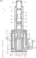
FIG. 1 is a cross-sectional view illustrating a solenoid valve according to a first embodiment of the present invention. -
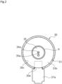
FIG. 2 is a partial cross-sectional view of the solenoid valve when viewed on the second end side in the axial direction. -
FIG. 3A and 3B are main part enlarged side cross-sectional views illustrating an OFF state of the solenoid valve and an ON state of the solenoid valve, respectively. -
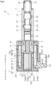
FIG. 4 is a side cross-sectional view illustrating a solenoid valve according to a second embodiment of the present invention. - Modes for implementing a solenoid valve according to the present invention will be described below based on embodiments.
- A solenoid valve according to a first embodiment of the present invention will be described with reference to
FIGS. 1 and2 . Hereinafter, the right side of the drawing sheet ofFIG. 1 and the left side of the drawing sheet ofFIG. 1 will be described as one axial end side of the solenoid valve and the other axial end side of the solenoid valve, respectively. - As illustrated in
FIG. 1 , asolenoid valve 1 according to the first embodiment of the present embodiment is a spool-type solenoid valve and is used in, for example, a hydraulically controlled apparatus such as an automatic transmission for a vehicle. Incidentally, thesolenoid valve 1 is used as a so-called oil-immersed solenoid valve that is attached to a mounting hole of a valve housing on an apparatus side in a horizontal direction, and that is immersed in a hydraulic oil which is a liquid inside the valve housing. - The
solenoid valve 1 is configured such that avalve unit 2 which adjusts the flow rate of a fluid, namely, a control fluid such as a hydraulic oil is integrally attached to asolenoid unit 3. Incidentally,FIG. 1 illustrates an OFF state of thesolenoid valve 1 in which acoil 36 of a solenoid moldedbody 31 is not energized. - First, a structure of the
valve unit 2 will be described. As illustrated inFIG. 1 , thevalve unit 2 includes asleeve 21 provided with openings of various ports such as aninput port 24, anoutput port 25, adischarge port 26, adrain port 27, and afeedback port 28 that are connected to flow passages provided in the mounting hole of the valve housing; aspool 22 as a valve body that is liquid-tightly accommodated in a through-hole 21a formed in an axial direction on a radially inner side of thesleeve 21; aspring 29 having a coil shape which biases thespool 22 toward the other axial end side; and aretainer 23 that holds thespring 29. - In the
sleeve 21, thedischarge port 26, theoutput port 25, theinput port 24, thefeedback port 28, and thedrain port 27 are formed in order from the one axial end side toward the other axial end side. Thespool 22 is reciprocatable in the axial direction, and thespool 22 is reciprocated in the axial direction to change communication states of the various ports and to control the pressure or flow rate of the hydraulic oil. Incidentally, thesleeve 21, thespool 22, and theretainer 23 are made of a material such as aluminum, iron, stainless steel, or resin. - Next, a structure of the
solenoid unit 3 will be described. As illustrated inFIG. 1 , thesolenoid unit 3 mainly includes asolenoid casing 30 having a tubular shape; the solenoid moldedbody 31 accommodated in thesolenoid casing 30; astator 32 disposed on the one axial end side inside the solenoid moldedbody 31; aside ring 33 as a yoke disposed on the other axial end side inside the solenoid moldedbody 31; anend plate 34 as a lid member that closes an opening at the other axial end of thesolenoid casing 30; and aplunger 35 as a movable iron core that is disposed to be movable in the axial direction in a space surrounded by thestator 32, atubular body 7 to be described later, theside ring 33, and theend plate 34. - The
solenoid casing 30 is a tubular body made of a metal material having a magnetic property such as iron, and thesleeve 21 is connected to one axial end of thesolenoid casing 30. In addition, an opening 30a penetrating through thesolenoid casing 30 in a radial direction is formed in a lower portion at the other axial end of thesolenoid casing 30 by cutting out thesolenoid casing 30 from the other axial end side (refer toFIG. 2 ). - In addition, a crimping
portion 30b having a C shape in an axial view is provided at the other axial end of thesolenoid casing 30, namely, at a portion other than the opening 30a, and the crimpingportion 30b is crimped on a radially inner side, so that theend plate 34 is sandwiched between the crimpingportion 30b and aflange portion 33b of theside ring 33. - The
end plate 34 is made of a metal material having a magnetic property such as iron, and is a disc having a slightly larger diameter than that of theflange portion 33b of theside ring 33. Aprotrusion 34a protruding toward aplunger 35 side is formed on a radial center of theend plate 34. - The solenoid molded
body 31 is formed by molding thecoil 36 withresin 37, and includes aconnector portion 37a projecting from the other radial end of the solenoid moldedbody 31 in a radially outward direction, and having a substantially L-shaped cross section formed by a root portion and a terminal portion. The root portion of theconnector portion 37a is fitted to the opening 30a of thesolenoid casing 30 from the other axial end side, and the terminal portion of theconnector portion 37a is disposed to extend toward the one end side (also referred to as a first end side) outside thesolenoid casing 30. A control electric current is supplied to thecoil 36 from the terminal portion of theconnector portion 37a. - The
stator 32 is a tubular body having a through-hole 32a with a step in a central portion thereof, the through-hole 32a penetrating therethrough in the axial direction, and is made of a metal material having a magnetic property such as iron. In the through-hole 32a, a portion on the other end side (also referred to as a second end side) in the axial direction is a large-diameter hole portion 32b, and a portion on the one axial end side is a small-diameter hole portion 32c having a smaller diameter than that of the large-diameter hole portion 32b. - In addition, a
damper member 6 having a ring shape which is made of a non-magnetic material such as resin or rubber is firmly fixed to an annular surface of thestator 32, the annular surface being orthogonal to the axial direction and being formed between an inner peripheral surface forming the large-diameter hole portion 32b and an inner peripheral surface forming the small-diameter hole portion 32c. In addition, the other axial end of thespool 22 can come into contact with one axial end of thestator 32, and the movement of thespool 22 toward the other axial end side is restricted. - The
side ring 33 is made of a metal material having a magnetic property such as iron. In theside ring 33, atubular portion 33a that extends in the axial direction and that is disposed inside the solenoid moldedbody 31, and theflange portion 33b having an annular shape which projects radially outward from the other axial end of thetubular portion 33a, namely, an end portion on anend plate 34 side are formed. Theflange portion 33b is disposed on the other axial end side with respect to the solenoid moldedbody 31. - As illustrated in
FIGS. 1 and2 , theflange portion 33b is formed such that an outer circumference and an inner circumference are concentric with each other and a thickness is substantially constant, and an annular outerperipheral surface 33c of theflange portion 33b continuously extends in a circumferential direction in an annular shape. In other words, theflange portion 33b has the annular outerperipheral surface 33c without a cutout portion, and is formed in a ring shape in an axial view. Namely, the annular outerperipheral surface 33c of theflange portion 33b is in arc contact with an innerperipheral surface 30c of thesolenoid casing 30. - In addition, a lower portion of the annular outer
peripheral surface 33c of theflange portion 33b, namely, a part of the annular outerperipheral surface 33c in the circumferential direction is exposed to the outside through theopening 30a of thesolenoid casing 30. - In addition, the
tubular body 7 made of a non-magnetic material is disposed between thestator 32 and theside ring 33. Abushing 9 made of a non-magnetic material is disposed over thetubular body 7 and theside ring 33 inside thetubular body 7 and theside ring 33. - The
plunger 35 is formed in a columnar shape from a metal material having a magnetic property such as iron, and is slidably disposed inside thebushing 9. An outer peripheral surface of theplunger 35 and an inner peripheral surface of thebushing 9 are slightly separated from each other. - A space S1 that does not communicate with and is partitioned off from an external space of the
solenoid casing 30 is formed on the other axial end side of theplunger 35, and a space S2 that does not communicate with and is partitioned off from the external space of thesolenoid casing 30 is formed on one axial end side of theplunger 35. A through-hole 35a penetrating through theplunger 35 in parallel to a central axis is formed in theplunger 35 at an eccentric position, and allows communication between the space S1 and the space S2. - Specifically, the space S1 is partitioned off by the
plunger 35, theside ring 33, and theend plate 34, and the space S2 is partitioned off by theplunger 35, the through-hole 32a of thestator 32, and thespool 22. Incidentally, a space S3 inside thesleeve 21 is partitioned off from the spaces S1 and S2 by thespool 22. - The other end of the
rod 5 that is slidably inserted into the small-diameter hole portion 32c of thestator 32 is in contact with anend surface 35b on the one end side of theplunger 35, and one end of therod 5 abuts the other end of thespool 22. Incidentally, the one end of therod 5 may not abut theend surface 35b on the one end side of theplunger 35 when an electric current is turned off. - Next, an operation of the
solenoid valve 1 will be described. As illustrated inFIG. 3A , in an OFF state of thesolenoid valve 1, thespool 22 is biased toward the other axial end side by a biasing force of the spring 29 (refer toFIG. 1 ), and accordingly, theplunger 35 and therod 5 are moved to the other axial end side. - At this time, the
protrusion 34a of theend plate 34 abuts a center of anend surface 35d on the other axial end side of theplunger 35. Specifically, theprotrusion 34a of theend plate 34 abuts theend surface 35d of theplunger 35 at a position different from that of the through-hole 35a, and accordingly, the movement of theplunger 35 toward the other axial end side is restricted. - As illustrated in
FIG. 3B , in an ON state of thesolenoid valve 1, since thecoil 36 is energized, a magnetic circuit is formed by thesolenoid casing 30, theend plate 34, theside ring 33, theplunger 35, and thestator 32, and a magnetic force is generated between thestator 32 and theplunger 35, so that theplunger 35 and therod 5 move toward astator 32 side in the axial direction. - Accordingly, the one axial end of the
rod 5 pushes an end surface on the other axial end side of thespool 22 to move thespool 22 toward the one axial end side against the biasing force of thespring 29, thereby being able to change the amount of the control fluid flowing from theinput port 24 to theoutput port 25 of thesleeve 21. Incidentally, theend surface 35b of theplunger 35 abuts thedamper member 6, so that the movement of theplunger 35 toward the one axial end side is restricted. - In addition, when the
spool 22 has moved to the one axial end side, the fluid in the space S2 moves to the space S1 through the through-hole 35a of theplunger 35. Accordingly, the fluid in the space S2 can be prevented from becoming resistance to movement of theplunger 35 toward the one axial end side, and responsiveness of thesolenoid valve 1 can be improved. - In addition, when the
coil 36 is de-energized and the magnetic force generated between thestator 32 and theplunger 35 becomes relatively weak, thespool 22 is moved toward the other axial end side by the biasing force of thespring 29, and accordingly, theplunger 35 and therod 5 move toward the other axial end side (refer toFIGS. 1 and3A ). At this time, the fluid in the space S1 flows to the space S2 through the through-hole 35a of theplunger 35. Accordingly, the fluid in the space S1 can be prevented from becoming resistance to movement of theplunger 35 toward the other axial end side, and responsiveness of thesolenoid valve 1 can be improved. - As described above, the
flange portion 33b of theside ring 33 has the annular outerperipheral surface 33c that is continuous, and is disposed on the other end side of the solenoid moldedbody 31. According to this configuration, since the annular outerperipheral surface 33c of theflange portion 33b is continuously formed in an annular shape, a cutout is not formed in theflange portion 33b, and theflange portion 33b has a uniform shape in the circumferential direction, so that a magnetic efficiency is good and a magnetic force can act on theplunger 35 in a well-balanced manner. - In addition, since the
side ring 33 has a uniform shape in the circumferential direction, a relative circumferential assembly direction of the solenoid moldedbody 31 and theside ring 33 is not limited, and assembly work can be easily performed. - In addition, since the
end plate 34 abuts theflange portion 33b in an annular shape in the axial direction, theflange portion 33b having an annular shape in an axial view in which a cutout is not formed, a wide abutting area can be ensured, and contaminations are unlikely to intrude into the space S1. - In addition, since the
end plate 34 is made of a magnetic material, the volume of portions forming a magnetic circuit is large, and the magnetic efficiency is improved. Further, since theend plate 34 has a disc shape without a cutout in the circumferential direction, a magnetic force can act on theplunger 35 in a well-balanced manner. - In addition, since the
end plate 34 is sandwiched between the crimpingportion 30b of thesolenoid casing 30 and theflange portion 33b of theside ring 33, a magnetic circuit can be reliably formed between thesolenoid casing 30, theend plate 34, and theflange portion 33b of theside ring 33. - In addition, the spaces S1 and S2 that do not communicate with and are partitioned off from the external space of the
solenoid valve 1 are formed on both respective axial sides of theplunger 35, and the through-hole 35a that allows communication between the space S1 and the space S2 is formed in theplunger 35. In addition, theprotrusion 34a protruding toward theplunger 35 side is formed on theend plate 34, and theprotrusion 34a abuts theend surface 35d of theplunger 35 at a position different from that of the through-hole 35a. - According to this configuration, when the
plunger 35 has moved to theend plate 34 side, since theplunger 35 abuts theprotrusion 34a, the through-hole 35a of theplunger 35 is not closed by theend plate 34, so that the fluid can smoothly move between the space S2 on the one axial end side and the space S1 on the other axial end side of theplunger 35. In addition, since the spaces S1 and S2 that do not communicate with and are partitioned off from the external space of thesolenoid valve 1, contaminations are unlikely to intrude from the external space. - In addition, the
solenoid casing 30 includes theopening 30a through which theconnector portion 37a of the solenoid moldedbody 31 extends, theconnector portion 37a projecting in the radially outward direction, and the lower portion of the annular outerperipheral surface 33c of theflange portion 33b, namely, a part of the annular outerperipheral surface 33c in the circumferential direction is exposed to the outside through theopening 30a of thesolenoid casing 30. According to this configuration, since a part of the annular outerperipheral surface 33c of theflange portion 33b is exposed to the outside through theopening 30a, magnetic fluxes generated between thesolenoid casing 30 and theflange portion 33b at theopening 30a are unlikely to be blocked by theconnector portion 37a, and magnetic fluxes are easily generated in a well-balanced manner. In addition, since theconnector portion 37a does not interfere with theflange portion 33b when thesolenoid valve 1 is assembled, assembly work can be easily performed. - In addition, since the other end surface of the
connector portion 37a is formed to be flush with the other end surface of a portion of the solenoid moldedbody 31 in the radial direction, the portion being disposed inside thesolenoid casing 30 in the radial direction, theconnector portion 37a is easily manufactured. - In addition, since the other end surface of the
connector portion 37a is located on the one axial end side with respect to theflange portion 33b of theside ring 33, theopening 30a serves as a relief margin when thesolenoid casing 30 is deformed by a force acting when crimping is performed, and as a region where a crimping jig is movable, and the crimpingportion 30b can be easily crimped even in the vicinity of theopening 30a. - Incidentally, in the present embodiment, a mode has been provided in which the
end plate 34 is made of a magnetic material, but the end plate may be made of a non-magnetic material such as resin. - Next, a solenoid valve according to a second embodiment of the present invention will be described with reference to
FIG. 4 . Incidentally, a description of duplicated configurations that are the same as the configurations of the foregoing embodiment will be omitted. - A
side ring 330 of asolenoid valve 10 according to the second embodiment of the present invention includes atubular portion 330a disposed inside the solenoid moldedbody 31; aflange portion 330b projecting radially outward from the other axial end of thetubular portion 330a; and alid portion 330d that closes an opening of theflange portion 330b. Thelid portion 330d has a thinner thickness in the axial direction than that of theflange portion 330b, and an end surface on the other axial end side of thelid portion 330d extends to be flush with an end surface on the other axial end side of theflange portion 330b. - In addition, a
protrusion 330e protruding toward theplunger 35 side is formed on a radial center of thelid portion 330d. In an OFF state of thesolenoid valve 10, theprotrusion 330e abuts theend surface 35d of theplunger 35 at a position different from that of the through-hole 35a. - The
flange portion 330b of theside ring 330 is sandwiched between the crimpingportion 30b and the other axial end surface of the solenoid moldedbody 31 by crimping the crimpingportion 30b of thesolenoid casing 30. - In such a manner, since the other axial end of the
solenoid casing 30 is closed by thelid portion 330d forming a part of theflange portion 330b, the volume of portions forming a magnetic circuit is increased to improve the magnetic efficiency, and a magnetic force can act on theplunger 35 in a well-balanced manner. - In addition, since the
flange portion 330b of theside ring 330 is crimp-fixed by the crimpingportion 30b of thesolenoid casing 30, a magnetic circuit can be reliably formed between thesolenoid casing 30 and theflange portion 330b of theside ring 330. - In addition, since it is not necessary to prepare a lid member that closes the other axial end of the
solenoid casing 30, separately from theside ring 330, the number of components can be reduced, and assembly work can be easily performed. - In addition, since the
flange portion 330b of theside ring 330 and thelid portion 330d are integrally formed, contaminations can be prevented from intruding into the space S1 from the external space. - In addition, since the
side ring 330 is provided with theprotrusion 330e that abuts theend surface 35d of theplunger 35 at a position different from that of the through-hole 35a in an OFF state of thesolenoid valve 10, the through-hole 35a of theplunger 35 is not closed by thelid portion 330d in an OFF state of thesolenoid valve 10, and the fluid can smoothly move between the space S1 and the space S2. - Incidentally, a mode has been provided in which the
side ring 330 of the present embodiment is attached by sandwiching theflange portion 330b between the crimpingportion 30b of thesolenoid casing 30 and the other axial end surface of the solenoid moldedbody 31, but theside ring 330 may be attached by being sandwiched between the crimpingportion 30b of thesolenoid casing 30 and thetubular body 7, and in this case, theflange portion 330b may not abut the other axial end surface of the solenoid moldedbody 31. - The embodiments of the present invention have been described above with reference to the drawings, but the specific configurations are not limited to the embodiments, and the present invention also includes changes or additions that are made without departing from the scope of the present invention.
- For example, in the first and second embodiments, a mode has been provided in which the other end of the
rod 5 is in contact with theend surface 35b of theplunger 35 and the one end of therod 5 abuts the other end of thespool 22, but therod 5 may be fixed to theplunger 35 or to thespool 22 by a fixing member such as a bolt, welding, bonding, or the like. - In addition, in the first and second embodiments, a mode has been provided in which in an ON state of the
solenoid valves plunger 35 is prevented from coming into contact with thestator 32 by thedamper member 6, but theplunger 35 may come into contact with thestator 32. - In addition, a mode has been provided in which in the first embodiment, the
connector portion 37a of the solenoid moldedbody 31 is disposed on the one axial end side with respect to theflange portion 33b, and in the second embodiment, theconnector portion 37a is disposed on the one axial end side with respect to theflange portion 330b, but the present invention is not limited to the mode, and a part of the connector portion may be disposed on a radially outer side of the annular outer peripheral surface of the flange portion. In other words, the flange portion may be disposed on the other axial end side with respect to a portion of the solenoid molded body disposed inside the solenoid casing in the radial direction, namely, a portion of the solenoid molded body other than the connector portion. - In addition, in the first and second embodiments, a mode has been provided in which the through-
hole 35a is formed in theplunger 35, but the present invention is not limited to the mode, and instead of the through-hole 35a, a groove that allows communication between the space S1 and the space S2 may be formed in a side surface of theplunger 35. - In addition, in the first and second embodiments, a mode has been provided in which the space S1 on the other axial end side of the
plunger 35 and the space S2 on the one axial end side of theplunger 35 do not communicate with the external space of the solenoid valve, but one of or both the spaces S1 and S2 may communicate with the external space of the solenoid valve. Incidentally, when both the spaces S1 and S2 communicate with the external space of the solenoid valve, the through-hole 35a may not be formed in theplunger 35 since each of the spaces S1 and S2 can breathe with the external space. - In addition, a mode has been provided in which the other end of the
solenoid casing 30 is closed by theend plate 34 in the first embodiment and by theflange portion 330b of theside ring 330 in the second embodiment, but the present invention is not limited to the mode, and the solenoid casing may include a lid portion that closes the other end of the solenoid casing. - In addition, in the first and second embodiments, the side ring and the stator are separate bodies, but the side ring and the stator may be integrally formed. In this case, it is preferable that a portion in which a cross-sectional area of a magnetic flux flow passage is narrow is formed in the middle of a portion extending in the axial direction so as to act a strong magnetic force on the movable iron core.
- In addition, in the embodiments, the spool-type solenoid valve using the spool as a valve body has been described, but the present invention is not limited to the configuration, and may be applied to a solenoid valve using a globe valve, a gate valve, or the like.
-
- 1
- Solenoid valve
- 2
- Valve unit
- 3
- Solenoid unit
- 10
- Solenoid valve
- 30
- Solenoid casing
- 30a
- Opening
- 30b
- Crimping portion
- 31
- Solenoid molded body
- 32
- Stator
- 33
- Side ring (yoke)
- 33a
- Tubular portion
- 33b
- Flange portion
- 33c
- Annular outer peripheral surface
- 34
- End plate (lid member)
- 34a
- Protrusion
- 35
- Plunger (movable iron core)
- 35a
- Through-hole
- 36
- Coil
- 37a
- Connector portion
- 330
- Side ring
- 330a
- Tubular portion
- 330b
- Flange portion
- 330d
- Lid portion
- 330e
- Protrusion
- S1 to S3
- Space
Claims (6)
- A solenoid valve, comprising:a valve body;a sleeve in which the valve body is accommodated;a solenoid casing which is connected to the sleeve on a first end side in an axial direction of the solenoid valve, and which is closed on a second end side opposed to the first end side in the axial direction;a solenoid molded body accommodated in the solenoid casing;a yoke including a tubular portion disposed inside the solenoid molded body, and a flange portion projecting radially outward from an end portion of the tubular portion on the second end side; anda movable iron core disposed to be movable in the axial direction inside the yoke,wherein the valve body is moved together with the movable iron core by energizing a coil of the solenoid molded body, andthe flange portion has an annular outer peripheral surface that is continuous, and is disposed on the second end side of the solenoid molded body.
- The solenoid valve according to claim 1,
wherein an end portion of the solenoid casing on the second end side is closed by a lid member, and the lid member and the flange portion abut each other in an annular shape in the axial direction. - The solenoid valve according to claim 2,
wherein the lid member is made of a magnetic material. - The solenoid valve according to claim 1, wherein an end portion of the solenoid casing on the second end side is closed by the flange portion.
- The solenoid valve according to claim 4,
wherein the flange portion is crimp-fixed to the solenoid casing. - The solenoid valve according to claim 4 or 5,wherein a space on the second end side of the movable iron core does not communicate with and is partitioned off from an external space of the solenoid casing,a through-hole that allows communication between the space on the second end side of the movable iron core and a space on the first end side of the movable iron core is formed in the movable iron core, andthe flange portion includes a protrusion that is abuttable with respect to a portion of the movable iron core different from the through-hole.
Applications Claiming Priority (2)
| Application Number | Priority Date | Filing Date | Title |
|---|---|---|---|
| JP2021022850 | 2021-02-16 | ||
| PCT/JP2022/004923 WO2022176710A1 (en) | 2021-02-16 | 2022-02-08 | Solenoid valve |
Publications (2)
| Publication Number | Publication Date |
|---|---|
| EP4296552A1 true EP4296552A1 (en) | 2023-12-27 |
| EP4296552A4 EP4296552A4 (en) | 2025-01-01 |
Family
ID=82930510
Family Applications (1)
| Application Number | Title | Priority Date | Filing Date |
|---|---|---|---|
| EP22756031.5A Pending EP4296552A4 (en) | 2021-02-16 | 2022-02-08 | SOLENOID VALVE |
Country Status (5)
| Country | Link |
|---|---|
| US (1) | US12366304B2 (en) |
| EP (1) | EP4296552A4 (en) |
| JP (1) | JPWO2022176710A1 (en) |
| CN (1) | CN117043503A (en) |
| WO (1) | WO2022176710A1 (en) |
Families Citing this family (1)
| Publication number | Priority date | Publication date | Assignee | Title |
|---|---|---|---|---|
| JP7523249B2 (en) * | 2020-04-27 | 2024-07-26 | 川崎重工業株式会社 | Valve mechanism |
Family Cites Families (74)
| Publication number | Priority date | Publication date | Assignee | Title |
|---|---|---|---|---|
| US1049845A (en) | 1910-09-15 | 1913-01-07 | Geissinger Regulator Company | Electromagnetic valve. |
| US2654393A (en) | 1948-07-24 | 1953-10-06 | United Aircraft Prod | Two phase electromagnetic device |
| US2700397A (en) | 1949-08-24 | 1955-01-25 | Borg Warner | Unloading valve |
| US2650617A (en) | 1950-09-07 | 1953-09-01 | Missouri Automatic Contr Corp | Electromagnetic valve |
| US2999192A (en) | 1958-06-16 | 1961-09-05 | White Rodgers Company | Solenoid actuator and control means therefor |
| US3462116A (en) | 1964-02-06 | 1969-08-19 | Wright Components Inc | Solenoid valve and method for making the same |
| US3446473A (en) | 1964-11-23 | 1969-05-27 | Monsanto Co | Pulsed solenoid control valves |
| BE793385A (en) | 1971-12-29 | 1973-04-16 | Lucifer Sa | ELECTROMAGNETICALLY CONTROLLED FLUID VALVE |
| US3926405A (en) | 1974-08-21 | 1975-12-16 | Valcor Eng Corp | Solenoid operated proportional valve |
| JPS5565407A (en) | 1978-11-10 | 1980-05-16 | Minolta Camera Co Ltd | Electromagnetic mechanism |
| US4305566A (en) | 1979-10-31 | 1981-12-15 | Fluid Controls, Inc. | Fluid control valve |
| US4790345A (en) | 1987-03-17 | 1988-12-13 | Parker-Hannifin Corporation | Proportional valve |
| JPH0221378U (en) * | 1988-07-27 | 1990-02-13 | ||
| JPH0292907A (en) | 1988-09-30 | 1990-04-03 | Sekisui Chem Co Ltd | Vinyl chloride-based copolymer resin |
| JPH02129476A (en) | 1988-11-09 | 1990-05-17 | Aisin Aw Co Ltd | Pressure regulating valve |
| JPH03157576A (en) * | 1989-11-15 | 1991-07-05 | Aisin Aw Co Ltd | Three-way solenoid valve and manufacture thereof |
| DE3938136A1 (en) | 1989-11-16 | 1991-05-23 | Bosch Gmbh Robert | ELECTROMAGNETICALLY ACTUABLE VALVE |
| JP3016056B2 (en) | 1993-07-13 | 2000-03-06 | 日信工業株式会社 | Air gap adjustment method for normally closed solenoid valve and air gap and valve stroke adjustment method for normally open solenoid valve |
| US5413308A (en) | 1993-09-03 | 1995-05-09 | The Horton Company | Fail-open solenoid actuated valve |
| DE19510646C2 (en) | 1995-03-23 | 1997-09-18 | Bosch Gmbh Robert | Electromagnetically actuated pressure switching valve |
| JP3601554B2 (en) | 1995-08-11 | 2004-12-15 | アイシン・エィ・ダブリュ株式会社 | Solenoid pressure regulator |
| JPH09250650A (en) | 1996-03-18 | 1997-09-22 | Aichi Electric Co Ltd | Dimpproofing solenoid valve |
| JP3423581B2 (en) | 1997-07-22 | 2003-07-07 | リンナイ株式会社 | Latch type solenoid valve |
| DE19757475C2 (en) | 1997-12-23 | 1999-10-14 | Danfoss As | Servo-controlled solenoid valve |
| JPH11343820A (en) | 1998-06-03 | 1999-12-14 | Unisia Jecs Corp | Valve timing control device for internal combustion engine |
| DE19904901A1 (en) | 1999-02-06 | 2000-08-10 | Zahnradfabrik Friedrichshafen | Proportional pressure control valve |
| DE19934846A1 (en) | 1999-07-24 | 2001-01-25 | Hydraulik Ring Gmbh | Electromagnet and hydraulic valve with an electromagnet |
| JP2001143924A (en) * | 1999-11-15 | 2001-05-25 | Aisin Seiki Co Ltd | Electromagnet |
| DE19956160A1 (en) | 1999-11-23 | 2001-05-31 | Schaeffler Waelzlager Ohg | Magnetic valve, especially hydraulic proportional valve, has electromagnet and valve part joined radially, axially in force-locking and/or shape-locking manner by electromagnet pole shoe |
| JP2002027723A (en) | 2000-07-11 | 2002-01-25 | Denso Corp | Method of manufacturing electromagnetic drive device |
| JP2002181222A (en) | 2000-10-04 | 2002-06-26 | Denso Corp | Solenoid valve device and method of manufacturing the same |
| JP2002188747A (en) | 2000-12-22 | 2002-07-05 | Bosch Braking Systems Co Ltd | Solenoid valve and method of manufacturing the same |
| WO2002061314A1 (en) | 2001-01-31 | 2002-08-08 | Nok Corporation | Solenoid valve |
| JP2004360748A (en) | 2003-06-03 | 2004-12-24 | Nissin Kogyo Co Ltd | Normally open solenoid valve |
| JP4569371B2 (en) | 2005-04-28 | 2010-10-27 | 株式会社デンソー | Linear solenoid |
| FR2887005B1 (en) | 2005-06-14 | 2009-04-24 | Bontaz Ct Soc Par Actions Simp | SHOULDER RELEASE SOLENOID VALVE |
| JP2007211857A (en) | 2006-02-08 | 2007-08-23 | Denso Corp | Electromagnetic spool valve |
| JP4900074B2 (en) * | 2007-06-18 | 2012-03-21 | アイシン・エィ・ダブリュ株式会社 | solenoid valve |
| JP2009036328A (en) * | 2007-08-02 | 2009-02-19 | Denso Corp | Linear solenoid |
| JP2009250650A (en) | 2008-04-02 | 2009-10-29 | Seiko Epson Corp | Visual examination device and method for manufacturing semiconductor device |
| KR101168505B1 (en) * | 2008-05-29 | 2012-07-30 | 아이신에이더블류 가부시키가이샤 | Solenoid valve device |
| US8714179B2 (en) * | 2008-08-27 | 2014-05-06 | Eagle Industry Co., Ltd. | Solenoid valve |
| JP2010106899A (en) | 2008-10-29 | 2010-05-13 | Hitachi Automotive Systems Ltd | Solenoid valve |
| JP2010223279A (en) | 2009-03-20 | 2010-10-07 | Denso Corp | solenoid valve |
| US8585014B2 (en) * | 2009-05-13 | 2013-11-19 | Keihin Corporation | Linear solenoid and valve device using the same |
| JP5316263B2 (en) | 2009-06-30 | 2013-10-16 | 株式会社ジェイテクト | solenoid valve |
| JP2011077355A (en) * | 2009-09-30 | 2011-04-14 | Keihin Corp | Linear solenoid and valve device using the same |
| JP5077331B2 (en) | 2009-11-16 | 2012-11-21 | 株式会社デンソー | Linear solenoid |
| JP4844672B2 (en) | 2009-12-01 | 2011-12-28 | 株式会社デンソー | Linear solenoid |
| JP5387492B2 (en) | 2010-04-22 | 2014-01-15 | 株式会社デンソー | Linear solenoid |
| DE102010031334A1 (en) | 2010-07-14 | 2012-01-19 | Robert Bosch Gmbh | Solenoid valve and driver assistance device |
| JP5293792B2 (en) * | 2010-11-19 | 2013-09-18 | 株式会社デンソー | Hydraulic adjustment valve |
| JP5494681B2 (en) | 2012-01-13 | 2014-05-21 | 株式会社デンソー | solenoid valve |
| DE102012207584A1 (en) | 2012-05-08 | 2013-11-14 | Robert Bosch Gmbh | magnetic valve |
| DE102012104285A1 (en) | 2012-05-16 | 2013-11-21 | Svm Schultz Verwaltungs-Gmbh & Co. Kg | Valve |
| JP2014110372A (en) | 2012-12-04 | 2014-06-12 | Keihin Corp | Linear solenoid and linear solenoid valve, and method of manufacturing linear solenoid |
| DE202013100643U1 (en) | 2013-02-13 | 2013-02-21 | Bürkert Werke GmbH | magnetic valve |
| JP6245632B2 (en) | 2013-05-28 | 2017-12-13 | 株式会社ケーヒン | Linear solenoid valve |
| JP6115434B2 (en) | 2013-10-09 | 2017-04-19 | 株式会社デンソー | solenoid valve |
| JP2015137757A (en) | 2014-01-24 | 2015-07-30 | 株式会社ケーヒン | solenoid valve |
| JP6132035B2 (en) | 2014-01-29 | 2017-05-24 | アイシン・エィ・ダブリュ株式会社 | Electromagnetic drive device and method of manufacturing electromagnetic drive device |
| JP6265009B2 (en) | 2014-03-31 | 2018-01-24 | アイシン・エィ・ダブリュ株式会社 | Electromagnetic drive device and solenoid valve |
| JP2016089883A (en) | 2014-10-31 | 2016-05-23 | ニッタ株式会社 | Connecting mechanism of valve and joint in air piping |
| JP2016211657A (en) | 2015-05-08 | 2016-12-15 | 株式会社日本自動車部品総合研究所 | Spool valve |
| CN205190900U (en) | 2015-11-07 | 2016-04-27 | 余姚市三顺净水科技有限公司 | Guide's formula water inlet solenoid valve |
| JP2017157791A (en) | 2016-03-04 | 2017-09-07 | アイシン・エィ・ダブリュ株式会社 | Method of manufacturing solenoid valve core and solenoid valve core |
| KR101918532B1 (en) * | 2016-12-28 | 2018-11-15 | 주식회사 유니크 | Solenoid valve |
| DE102017207208A1 (en) | 2017-04-28 | 2018-10-31 | Robert Bosch Gmbh | Valve for adjusting a fluid flow |
| JP6563441B2 (en) | 2017-06-26 | 2019-08-21 | 株式会社不二工機 | Pilot operated solenoid valve |
| JP7016592B2 (en) | 2017-07-18 | 2022-02-07 | イーグル工業株式会社 | Solenoid valve |
| US11320061B2 (en) | 2017-11-22 | 2022-05-03 | Eagle Industry Co., Ltd. | Solenoid valve |
| CN111480024B (en) | 2017-11-22 | 2022-06-03 | 伊格尔工业股份有限公司 | Electromagnetic valve |
| JP2020088143A (en) * | 2018-11-26 | 2020-06-04 | 株式会社デンソー | solenoid |
| JP7171509B2 (en) * | 2019-05-24 | 2022-11-15 | イーグル工業株式会社 | solenoid valve |
-
2022
- 2022-02-08 US US18/277,378 patent/US12366304B2/en active Active
- 2022-02-08 WO PCT/JP2022/004923 patent/WO2022176710A1/en not_active Ceased
- 2022-02-08 EP EP22756031.5A patent/EP4296552A4/en active Pending
- 2022-02-08 CN CN202280015303.3A patent/CN117043503A/en active Pending
- 2022-02-08 JP JP2023500766A patent/JPWO2022176710A1/ja active Pending
Also Published As
| Publication number | Publication date |
|---|---|
| EP4296552A4 (en) | 2025-01-01 |
| CN117043503A (en) | 2023-11-10 |
| WO2022176710A1 (en) | 2022-08-25 |
| US20240125405A1 (en) | 2024-04-18 |
| US12366304B2 (en) | 2025-07-22 |
| JPWO2022176710A1 (en) | 2022-08-25 |
Similar Documents
| Publication | Publication Date | Title |
|---|---|---|
| EP2320114B1 (en) | Solenoid valve | |
| JPWO2011052371A1 (en) | Solenoid valve | |
| CN110036226B (en) | The electromagnetic valve | |
| US8141842B2 (en) | Solenoid valve | |
| JP2012204574A (en) | Linear solenoid | |
| US12366304B2 (en) | Solenoid valve | |
| JP7463356B2 (en) | Solenoid valve | |
| US12046418B2 (en) | Solenoid | |
| JP4492649B2 (en) | Bleed valve device | |
| JP4703615B2 (en) | Bleed valve device | |
| JP7007218B2 (en) | Solenoid valve | |
| CN115427716B (en) | solenoid valve | |
| EP3967911B1 (en) | Solenoid valve | |
| US11948737B2 (en) | Solenoid | |
| US11908620B2 (en) | Solenoid | |
| WO2024210067A1 (en) | Solenoid | |
| JP2024159215A (en) | Solenoid and method for assembling same | |
| WO2023195386A1 (en) | Valve and valve assembly method | |
| JP2008095813A (en) | Bleed valve device |
Legal Events
| Date | Code | Title | Description |
|---|---|---|---|
| STAA | Information on the status of an ep patent application or granted ep patent |
Free format text: STATUS: THE INTERNATIONAL PUBLICATION HAS BEEN MADE |
|
| PUAI | Public reference made under article 153(3) epc to a published international application that has entered the european phase |
Free format text: ORIGINAL CODE: 0009012 |
|
| STAA | Information on the status of an ep patent application or granted ep patent |
Free format text: STATUS: REQUEST FOR EXAMINATION WAS MADE |
|
| 17P | Request for examination filed |
Effective date: 20230825 |
|
| AK | Designated contracting states |
Kind code of ref document: A1 Designated state(s): AL AT BE BG CH CY CZ DE DK EE ES FI FR GB GR HR HU IE IS IT LI LT LU LV MC MK MT NL NO PL PT RO RS SE SI SK SM TR |
|
| DAV | Request for validation of the european patent (deleted) | ||
| DAX | Request for extension of the european patent (deleted) | ||
| A4 | Supplementary search report drawn up and despatched |
Effective date: 20241203 |
|
| RIC1 | Information provided on ipc code assigned before grant |
Ipc: F16K 31/06 20060101AFI20241127BHEP |