EP4296461A1 - Door hinge - Google Patents
Door hinge Download PDFInfo
- Publication number
- EP4296461A1 EP4296461A1 EP22180743.1A EP22180743A EP4296461A1 EP 4296461 A1 EP4296461 A1 EP 4296461A1 EP 22180743 A EP22180743 A EP 22180743A EP 4296461 A1 EP4296461 A1 EP 4296461A1
- Authority
- EP
- European Patent Office
- Prior art keywords
- door
- base body
- hinge
- seesaw
- bearing element
- Prior art date
- Legal status (The legal status is an assumption and is not a legal conclusion. Google has not performed a legal analysis and makes no representation as to the accuracy of the status listed.)
- Withdrawn
Links
- 238000013016 damping Methods 0.000 claims abstract description 24
- 238000006073 displacement reaction Methods 0.000 claims description 10
- 239000012530 fluid Substances 0.000 claims description 10
- 229910000831 Steel Inorganic materials 0.000 description 1
- XAGFODPZIPBFFR-UHFFFAOYSA-N aluminium Chemical compound [Al] XAGFODPZIPBFFR-UHFFFAOYSA-N 0.000 description 1
- 229910052782 aluminium Inorganic materials 0.000 description 1
- 239000004411 aluminium Substances 0.000 description 1
- 230000006835 compression Effects 0.000 description 1
- 238000007906 compression Methods 0.000 description 1
- 230000003993 interaction Effects 0.000 description 1
- 239000000463 material Substances 0.000 description 1
- 239000010959 steel Substances 0.000 description 1
Images

Classifications
-
- E—FIXED CONSTRUCTIONS
- E05—LOCKS; KEYS; WINDOW OR DOOR FITTINGS; SAFES
- E05F—DEVICES FOR MOVING WINGS INTO OPEN OR CLOSED POSITION; CHECKS FOR WINGS; WING FITTINGS NOT OTHERWISE PROVIDED FOR, CONCERNED WITH THE FUNCTIONING OF THE WING
- E05F3/00—Closers or openers with braking devices, e.g. checks; Construction of pneumatic or liquid braking devices
- E05F3/20—Closers or openers with braking devices, e.g. checks; Construction of pneumatic or liquid braking devices in hinges
-
- E—FIXED CONSTRUCTIONS
- E05—LOCKS; KEYS; WINDOW OR DOOR FITTINGS; SAFES
- E05F—DEVICES FOR MOVING WINGS INTO OPEN OR CLOSED POSITION; CHECKS FOR WINGS; WING FITTINGS NOT OTHERWISE PROVIDED FOR, CONCERNED WITH THE FUNCTIONING OF THE WING
- E05F1/00—Closers or openers for wings, not otherwise provided for in this subclass
- E05F1/08—Closers or openers for wings, not otherwise provided for in this subclass spring-actuated, e.g. for horizontally sliding wings
- E05F1/10—Closers or openers for wings, not otherwise provided for in this subclass spring-actuated, e.g. for horizontally sliding wings for swinging wings, e.g. counterbalance
- E05F1/12—Mechanisms in the shape of hinges or pivots, operated by springs
- E05F1/1207—Mechanisms in the shape of hinges or pivots, operated by springs with a coil spring parallel with the pivot axis
-
- E—FIXED CONSTRUCTIONS
- E05—LOCKS; KEYS; WINDOW OR DOOR FITTINGS; SAFES
- E05F—DEVICES FOR MOVING WINGS INTO OPEN OR CLOSED POSITION; CHECKS FOR WINGS; WING FITTINGS NOT OTHERWISE PROVIDED FOR, CONCERNED WITH THE FUNCTIONING OF THE WING
- E05F1/00—Closers or openers for wings, not otherwise provided for in this subclass
- E05F1/08—Closers or openers for wings, not otherwise provided for in this subclass spring-actuated, e.g. for horizontally sliding wings
- E05F1/10—Closers or openers for wings, not otherwise provided for in this subclass spring-actuated, e.g. for horizontally sliding wings for swinging wings, e.g. counterbalance
- E05F1/12—Mechanisms in the shape of hinges or pivots, operated by springs
- E05F1/1207—Mechanisms in the shape of hinges or pivots, operated by springs with a coil spring parallel with the pivot axis
- E05F1/1223—Mechanisms in the shape of hinges or pivots, operated by springs with a coil spring parallel with the pivot axis with a compression or traction spring
-
- E—FIXED CONSTRUCTIONS
- E05—LOCKS; KEYS; WINDOW OR DOOR FITTINGS; SAFES
- E05F—DEVICES FOR MOVING WINGS INTO OPEN OR CLOSED POSITION; CHECKS FOR WINGS; WING FITTINGS NOT OTHERWISE PROVIDED FOR, CONCERNED WITH THE FUNCTIONING OF THE WING
- E05F3/00—Closers or openers with braking devices, e.g. checks; Construction of pneumatic or liquid braking devices
- E05F3/04—Closers or openers with braking devices, e.g. checks; Construction of pneumatic or liquid braking devices with liquid piston brakes
- E05F3/10—Closers or openers with braking devices, e.g. checks; Construction of pneumatic or liquid braking devices with liquid piston brakes with a spring, other than a torsion spring, and a piston, the axes of which are the same or lie in the same direction
-
- E—FIXED CONSTRUCTIONS
- E05—LOCKS; KEYS; WINDOW OR DOOR FITTINGS; SAFES
- E05F—DEVICES FOR MOVING WINGS INTO OPEN OR CLOSED POSITION; CHECKS FOR WINGS; WING FITTINGS NOT OTHERWISE PROVIDED FOR, CONCERNED WITH THE FUNCTIONING OF THE WING
- E05F3/00—Closers or openers with braking devices, e.g. checks; Construction of pneumatic or liquid braking devices
- E05F3/04—Closers or openers with braking devices, e.g. checks; Construction of pneumatic or liquid braking devices with liquid piston brakes
- E05F3/10—Closers or openers with braking devices, e.g. checks; Construction of pneumatic or liquid braking devices with liquid piston brakes with a spring, other than a torsion spring, and a piston, the axes of which are the same or lie in the same direction
- E05F3/104—Closers or openers with braking devices, e.g. checks; Construction of pneumatic or liquid braking devices with liquid piston brakes with a spring, other than a torsion spring, and a piston, the axes of which are the same or lie in the same direction with cam-and-slide transmission between driving shaft and piston within the closer housing
-
- E—FIXED CONSTRUCTIONS
- E05—LOCKS; KEYS; WINDOW OR DOOR FITTINGS; SAFES
- E05F—DEVICES FOR MOVING WINGS INTO OPEN OR CLOSED POSITION; CHECKS FOR WINGS; WING FITTINGS NOT OTHERWISE PROVIDED FOR, CONCERNED WITH THE FUNCTIONING OF THE WING
- E05F3/00—Closers or openers with braking devices, e.g. checks; Construction of pneumatic or liquid braking devices
- E05F3/04—Closers or openers with braking devices, e.g. checks; Construction of pneumatic or liquid braking devices with liquid piston brakes
- E05F3/10—Closers or openers with braking devices, e.g. checks; Construction of pneumatic or liquid braking devices with liquid piston brakes with a spring, other than a torsion spring, and a piston, the axes of which are the same or lie in the same direction
- E05F3/106—Closers or openers with braking devices, e.g. checks; Construction of pneumatic or liquid braking devices with liquid piston brakes with a spring, other than a torsion spring, and a piston, the axes of which are the same or lie in the same direction with crank-arm transmission between driving shaft and piston within the closer housing
-
- E—FIXED CONSTRUCTIONS
- E05—LOCKS; KEYS; WINDOW OR DOOR FITTINGS; SAFES
- E05D—HINGES OR SUSPENSION DEVICES FOR DOORS, WINDOWS OR WINGS
- E05D3/00—Hinges with pins
- E05D3/02—Hinges with pins with one pin
- E05D2003/025—Hinges with pins with one pin having three knuckles
- E05D2003/027—Hinges with pins with one pin having three knuckles the end knuckles being mutually connected
-
- E—FIXED CONSTRUCTIONS
- E05—LOCKS; KEYS; WINDOW OR DOOR FITTINGS; SAFES
- E05Y—INDEXING SCHEME ASSOCIATED WITH SUBCLASSES E05D AND E05F, RELATING TO CONSTRUCTION ELEMENTS, ELECTRIC CONTROL, POWER SUPPLY, POWER SIGNAL OR TRANSMISSION, USER INTERFACES, MOUNTING OR COUPLING, DETAILS, ACCESSORIES, AUXILIARY OPERATIONS NOT OTHERWISE PROVIDED FOR, APPLICATION THEREOF
- E05Y2201/00—Constructional elements; Accessories therefor
- E05Y2201/60—Suspension or transmission members; Accessories therefor
- E05Y2201/622—Suspension or transmission members elements
- E05Y2201/624—Arms
-
- E—FIXED CONSTRUCTIONS
- E05—LOCKS; KEYS; WINDOW OR DOOR FITTINGS; SAFES
- E05Y—INDEXING SCHEME ASSOCIATED WITH SUBCLASSES E05D AND E05F, RELATING TO CONSTRUCTION ELEMENTS, ELECTRIC CONTROL, POWER SUPPLY, POWER SIGNAL OR TRANSMISSION, USER INTERFACES, MOUNTING OR COUPLING, DETAILS, ACCESSORIES, AUXILIARY OPERATIONS NOT OTHERWISE PROVIDED FOR, APPLICATION THEREOF
- E05Y2201/00—Constructional elements; Accessories therefor
- E05Y2201/60—Suspension or transmission members; Accessories therefor
- E05Y2201/622—Suspension or transmission members elements
- E05Y2201/624—Arms
- E05Y2201/626—Levers
-
- E—FIXED CONSTRUCTIONS
- E05—LOCKS; KEYS; WINDOW OR DOOR FITTINGS; SAFES
- E05Y—INDEXING SCHEME ASSOCIATED WITH SUBCLASSES E05D AND E05F, RELATING TO CONSTRUCTION ELEMENTS, ELECTRIC CONTROL, POWER SUPPLY, POWER SIGNAL OR TRANSMISSION, USER INTERFACES, MOUNTING OR COUPLING, DETAILS, ACCESSORIES, AUXILIARY OPERATIONS NOT OTHERWISE PROVIDED FOR, APPLICATION THEREOF
- E05Y2201/00—Constructional elements; Accessories therefor
- E05Y2201/60—Suspension or transmission members; Accessories therefor
- E05Y2201/622—Suspension or transmission members elements
- E05Y2201/638—Cams; Ramps
-
- E—FIXED CONSTRUCTIONS
- E05—LOCKS; KEYS; WINDOW OR DOOR FITTINGS; SAFES
- E05Y—INDEXING SCHEME ASSOCIATED WITH SUBCLASSES E05D AND E05F, RELATING TO CONSTRUCTION ELEMENTS, ELECTRIC CONTROL, POWER SUPPLY, POWER SIGNAL OR TRANSMISSION, USER INTERFACES, MOUNTING OR COUPLING, DETAILS, ACCESSORIES, AUXILIARY OPERATIONS NOT OTHERWISE PROVIDED FOR, APPLICATION THEREOF
- E05Y2900/00—Application of doors, windows, wings or fittings thereof
- E05Y2900/10—Application of doors, windows, wings or fittings thereof for buildings or parts thereof
- E05Y2900/13—Type of wing
- E05Y2900/132—Doors
Definitions
- the present invention relates to a door hinge forming a hinge between a door leaf and a door frame, having a base body and having a bearing element, whereas the bearing element is rotatably received in the base body, and whereas a spring element is received in or at the base body, whereas between the bearing element and the spring element an interacting mechanism is arranged, and by said interacting mechanism the spring element compresses when the bearing element rotates relative to the base body.
- a prior art door hinge is known from KR 101958219 A , in which the base body is integrated into the door leaf, while the bearing element is received in the door frame, in particular forming a bottom side hinge for the door leaf in the door frame.
- the spring tensiles by interacting with a sloped receiving element, in which one end of the spring element is received. When the slope element rotates in a rotating axis, the spring compresses and the door can be led back e.g. into a closed position.
- the US 5,075,923 A teaches another embodiment of a door closer between a door leaf and a door frame, having a base body which is integrated in the door frame and a counter element, but this embodiment only forms a door closer without a hinge function.
- the invention discloses the technical teaching that a hydraulic system is arranged in or at the base body, whereas the hydraulic system features a damping link to the interacting mechanism for damping the rotation of the bearing element.
- the core idea of the invention is to provide a door hinge forming a hinge between door leaf and door frame which provides a restoring moment for the door leaf preferably into a closed position of the door leaf combined with a damping behaviour for damping the movement of the door leaf by applying a hydraulic system to the door hinge.
- the door hinge forms a hinge between the door leaf and the door frame in such a way that at least the base body and/or the bearing element must be integrable into the door leaf or the door frame, respectively.
- the inventive solution integrates and/or combines a hydraulic system into the door hinge as a unit, and the hydraulic system features a damping link to the interacting mechanism between the bearing element and the spring element.
- the damping link according to the invention can be a mechanical link and/or a fluidic link of the hydraulic system to the interacting mechanism.
- a common part can be provided which is a part of the mechanical interacting mechanism as well as a part of the hydraulic system. This common part can be pressurized by the hydraulic fluid of the hydraulic system across at least one surface of the common part.
- the spring element features a first spring end, whereas a piston is attached to the first spring end forming the damping link, and in particular forming the common part of the hydraulic system and of the interacting mechanism.
- the piston is displaceable arranged in a cylinder, whereas the cylinder can be a part of or at least combined with the base body.
- the cylinder can be at least partly filled with a hydraulic fluid of the hydraulic system and forms a part of the hydraulic system.
- the hydraulic system pressurizes the hydraulic fluid and can thus interact with the piston displaceable arranged in the cylinder.
- the piston which is displaceable arranged in the cylinder, forms the damping link between the hydraulic system and the interacting mechanism.
- the door hinge can fulfil two main objectives, namely providing a restoring moment of the door leaf preferably into a closed position preferred within the door frame and the providing a damping of the movement of the door leaf, similar to an external mounted door closer, but with the main function of the door hinge to form a hinge between the door leaf and the door frame.
- the door hinge can be integrated in the door leaf or at least in the door frame, in particular without protruding parts or sections of the door hinge protruding beyond the overall shape of the door leaf and/or of the door frame.
- This forms another main feature of the door hinge namely that the door hinge is integrated in the door leaf or/and the door frame as it is known from usual door hinges without a restoring moment and/or a damping function.
- the hydraulic system comprises at least one preferably adjustable valve through which the hydraulic fluid flows.
- two hydraulic valves are provided, which are adjustable for an operator person, in particular to adjust the damping force and/or the damping force behaviour across the entire swinging angle of the door leaf between an opened and a closed position.
- the adjustable formed valves can be operated by hand, by a tool, e.g. a screwdriver, by a hand wheel or similar.
- the interacting mechanism is formed in such a way that the hydraulic system can be at least partly integrated into the interacting mechanism.
- the hydraulic system can be spatial interleaved with the interacting mechanism, in order to minimize the entire space need of the door hinge comprising the interacting mechanism as well as the hydraulic system.
- the spatial interleaving can be optimized by an interacting mechanism comprising a seesaw element, which is received in a seesaw axis, and the seesaw axis is received in or at the base body.
- a first end of the seesaw element is connected to the first spring end and an opposing second end of the seesaw element is at least indirect interconnected to the bearing element.
- the interconnection between the second end of the seesaw element and the bearing element comprises an eccentric means and a displaceable means, which displaceable means interacts with the eccentric means and displaces, when the bearing element is rotated.
- the rotating movement of the bearing element can be transferred into a longitudinal movement of the displaceable means, and the displacement of the displaceable means causes a pivot movement of the seesaw element in the seesaw axis.
- the spring element can be compressed and released when the seesaw element pivots in the seesaw axis caused by rotating the bearing element.
- the bearing element and the eccentric element can be formed integrally in a one-piece and can comprise or feature a bearing ring for bearing the bearing element in the base body.
- a tilting means is arranged between the displaceable means and the second end of the seesaw element, whereas said tiling means is coupled to the displaceable means via a connecting hinge and is coupled to the second end of the seesaw element.
- This tiling means comprises a first tilting element which is connected to the displaceable means via the connecting hinge and a second tilting element which is connected to the second end of the seesaw element.
- the first tilting element is tiltable relative to the second tilting element in a tilting axis, in order to permit the displaceable means to perform a displacement while the seesaw element performs a seesaw movement in the seesaw axis and tensions and relaxes the spring element.
- the displacement of the displaceable means causes a displacement of the tilting means in such a direction that the seesaw element tilts in the seesaw axis.
- the entire interacting mechanism forms a C-mount from a side view perpendicular to a moving axis of the first spring end, comprising the elements between the bearing element and the spring element, beginning with the eccentric means, which is in direct interaction with the bearing element, or the eccentric means as a part of the bearing element, followed by the displaceable means, interacting with the eccentric means, and the displaceable means is followed by the tilting means, whereas the tilting means is connected to the displaceable means by a connecting hinge.
- the tilting means comprises a first tilting element and a second tilting element, whereas the tilting elements are rotatably interconnected in a tilting axis.
- the first tilting element is connected to the displaceable means and the second tilting element is connected to the second end of the seesaw element.
- the piston To the first end of the seesaw element the piston is attached, and to the piston the first spring end is attached, and when the seesaw element performs a seesaw movement in the seesaw axis, the spring can be compressed and released.
- the opposite second spring end is received in the base body and can preferably be combined with a screw element to adjust the pre-tension of the spring by an operating person.
- the displacement means In order to use the door hinge as a door closer with a feedback force for the door leaf and with the damping function by means of the hydraulic system, it is important to permit the displacement means a displacement, when the bearing means is rotating in a rotating axis forming the rotating axis of the door leaf.
- This displacement of the displaceable means is permitted in the tilting means, because the first tilting element is rotatable connected to the second tilting element, and due to the displacement of the displaceable means the displaceable means, the tilting means and thus the second end of the seesaw element displaces, causing a compression and release of the spring element.
- a rack-and-pinion arrangement can also be formed as an interacting mechanism between the bearing element and the displaceable means and can thus form an alternative to the interconnection basing in the eccentric element.
- the base body of the door hinge features a flat, box-like shape that is designed to be inserted into a door leaf or into a door frame.
- the base body can measure 6 cm to 8 cm, preferably 7.2 cm wide, 16 cm to 20 cm height and 10 cm to 13 cm depth.
- the base body is inserted into the door frame, but depending on the thickness of the door leaf, the base body can also be integrated into the door leaf.
- the elements of the interacting mechanism between the bearing element and the spring element, respectively, are received within the base body.
- the base body can form a closed housing or at least a frame with opened side faces.
- the base body can also be a design part of the door, like it is known for door hinges in only-glass-door-systems, in particular when the base body forms a designed surface e.g. made of high-grade steel or brushed aluminium.
- a second hinge element can be arranged at or in the base body, in particular at an opposite position at the base body relative to the bearing element.
- a counter element can be tiltable arranged to the base body, and the counter element can receive the door leaf or can be received in the door frame, depending on which side the base body is integrated.
- the hinge element and the bearing element form a common axis, which forms a tilting axis of the door leaf, and thus the tilting axis of the counter element which is arranged to the base body.
- FIG 1 is depicted the door hinge 100 in a perspective view and in figure 2 the door hinge 100 is shown in a side view with a partly opened base body 10.
- the door hinge 100 comprises a base body 10, which can be integrated into the door frame (or alternatively in the door leaf), and to the base body 10 is attached a counter element 26, which is tiltable in a common axis 27, forming the tilting axis between the door leaf in the door frame, whereas the door with the door leaf and the door frame are not shown.
- the counter element 26 features a fork-like arrangement, to encompass a part of the base body 10, and to form the tiltable arrangement of the counter element 26 at the base body 10 in the bearing element 11 as a first bearing and an opposite hinge element 25 as a second bearing, in such a way that the common axis 27 is defined by the bearing element 11 and the hinge element 25.
- the hydraulic system 14 is shown in conjunction with the base body 10, to which is attached a door part 30, which door part is tiltable relative to the counter element 26 in the common axis 27 in conjunction with the base body 10.
- the interacting mechanism 13 is arranged within the base body 10 for forming a mechanical interconnection between the bearing element 11 and the spring element 12.
- the spring element 12 features a first spring end 12a and a second spring end 12b, whereas the first spring end 12a is received in a piston 16 and the second spring end 12b is received in the bottom side of the base body 10 in or next to the hinge element 25.
- the piston 16 forms a damping link 15 between the interacting mechanism 13 and the hydraulic system 14, which is attached to or received in the base body 10 and attached to the base body 10 is attached the door part 30.
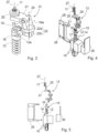
- FIG 3 the interacting mechanism 13 between the bearing element 11 and the spring element 12 is shown in a perspective view, whereas the interacting mechanism 13 is mounted.
- Figure 4 and figure 5 show the same embodiment of the interacting mechanism 13 in a perspective view ( fig. 4 ) and in a side view ( fig. 5 ) in an un-mounted state next to the counter element 26 and the door part 30.
- a piston 16 To the first spring end 12a of the spring element 12 is arranged a piston 16, whereas said piston 16 is displaceable arranged in a cylinder 17, whereas the cylinder 17 is as an example only a part of the base body 10 or at least integrated in the base body 10.
- the cylinder 17 is filled with a hydraulic fluid and forms a fluid reservoir of the hydraulic system 14, so that when the piston 16 displaces in the cylinder 17, the piston 16 forms a damping link 15 to the hydraulic system 14.
- the interacting mechanism 13 comprises a seesaw element 19, which is pivotally received in a seesaw axis 19a, and the seesaw axis 19a is received in the base body 10.
- a first end of the seesaw element 19 is connected to piston 16 via a rotating axis. Piston 16 is further pressed on first spring end 12a. The opposing second end of the seesaw element 19 is indirect interconnected to the bearing element 11 via the remaining parts of the interacting mechanism 13.
- the interconnection between the second end of the seesaw element 19 and the bearing element 11 comprises an eccentric means 20 and a displaceable means 21, which displaceable means 21 interacts with the eccentric means 20 and displaces when the bearing element 11 is rotated.
- the eccentric means 20 is received in a receiving hole 28 in the displaceable means 21, and when the bearing element 11 rotates in the common axis 27, the displaceable means 21 fulfils a planar movement according to the excentre of the eccentric means.
- the tilting means 22 comprises a first tilting element 22a and a second tilting element 22b, and both tilting elements 22a, 22b can tilt against each other in a tilting axis 24, in order to permit the displaceable means 21 a displacement while the seesaw element 19 performs a seesaw movement in the seesaw axis 19a and tensions and relaxes the spring element 12.
- the depictions in the related figures also show the counter element 26, which is designed to be received in a door leaf, whereas the door hinge 100 operates as a door closer comprising a damping effect between the counter element 26 and the door part 30, which door part 30 may represent a part of the door leaf or the door frame or a part which can be mounted to the door leaf or the door frame and relates to a part of the door hinge 100 itself.
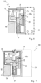
- Figure 6 and figure 7 show the door hinge 100 in different cross section layers, whereas the interacting mechanism 13 is received within the base body 10, and the counter element 26 as well as the door part 30 are attached to the base body 10.
- the hydraulic system 14 is shown with hydraulic lines 29, and two different valves 18a and 18b are shown in the hydraulic lines 29, which valves 18a, 18b differ from each other, and the valves 18a, 18b can be adjusted by an operating person.
- valves 18a, 18b are thought to control the inner flow and outer flow of the hydraulic fluid F in and out of the cylinder 17, which cylinder forms the main part of the hydraulic system 14, in which the piston 16 is displaceable received.
- a damping link 15 is formed between the interacting mechanism 13 and the hydraulic system 14.
- the valves 18a, 18b e.g. the closing speed of the door leaf between the open position and the closed position can be adjusted or the closing speed can be formed with a closing speed profile over the entire closing angle.
- the valves 18a, 18b lie in different layers, whereas figure 6 shows the first valve 18a in a first layer representing the first cross section and figure 7 shows the second valve 18b in a second layer representing the second cross section.
- the present invention is not limited by the described above, which is represented as an example only and can be modified in various ways within the scope of protection defined by the appending patent claims.
- the invention is also applicable to different embodiments, in particular of the design, of the interacting mechanism 13 and the position of the spring element 12.
- the elongation direction of the spring element 12 can be perpendicular to the direction of the common axis 27 forming the rotating axis for the bearing element 11 and thus for the door leaf.
Landscapes
- Closing And Opening Devices For Wings, And Checks For Wings (AREA)
Abstract
The invention relates to a door hinge (100) forming a hinge between a door leaf and a door frame, having a base body (10) and having a bearing element (11), whereas the bearing element (11) is rotatably received in the base body (10), and whereas a spring element (12) is received in or at the base body (10), whereas between the bearing element (11) and the spring element (12) is arranged an interacting mechanism (13), and by said interacting mechanism (13) the spring element (12) compresses when the bearing element (11) rotates relative to the base body (10). According to the invention a hydraulic system (14) is arranged in or at the base body (10), whereas the hydraulic system (14) features a damping link (15) to the interacting mechanism (13) for damping the rotation of the bearing element (11).
Description
- The present invention relates to a door hinge forming a hinge between a door leaf and a door frame, having a base body and having a bearing element, whereas the bearing element is rotatably received in the base body, and whereas a spring element is received in or at the base body, whereas between the bearing element and the spring element an interacting mechanism is arranged, and by said interacting mechanism the spring element compresses when the bearing element rotates relative to the base body.
- Door hinges with a door closer function by means of a compressible spring are already known. A prior art door hinge is known from
KR 101958219 A - The
US 5,075,923 A teaches another embodiment of a door closer between a door leaf and a door frame, having a base body which is integrated in the door frame and a counter element, but this embodiment only forms a door closer without a hinge function. - It is a first object of the present invention to provide an improved door hinge forming a hinge between a door leaf and a door frame, which door hinge can easily be integrated into the door leaf or the door frame. Accordingly, the door hinge must have a slender overall design, and in particular the base body containing the spring element must be integrable into the door leaf or, at least, into the door frame. Moreover, it is the objective of the invention to enlarge the functionality of the door hinge, in particular regarding a damping function. The main object is to enlarge the functionality of the door hinge.
- This object is achieved by a door hinge with a door closer function as taught by claim 1 of the present invention. Advantageous embodiments of the inventive system are defined in the sub-claims.
- The invention discloses the technical teaching that a hydraulic system is arranged in or at the base body, whereas the hydraulic system features a damping link to the interacting mechanism for damping the rotation of the bearing element.
- The core idea of the invention is to provide a door hinge forming a hinge between door leaf and door frame which provides a restoring moment for the door leaf preferably into a closed position of the door leaf combined with a damping behaviour for damping the movement of the door leaf by applying a hydraulic system to the door hinge. In conjunction with this core idea of the invention the door hinge forms a hinge between the door leaf and the door frame in such a way that at least the base body and/or the bearing element must be integrable into the door leaf or the door frame, respectively.
- The inventive solution integrates and/or combines a hydraulic system into the door hinge as a unit, and the hydraulic system features a damping link to the interacting mechanism between the bearing element and the spring element. The damping link according to the invention can be a mechanical link and/or a fluidic link of the hydraulic system to the interacting mechanism. For example, a common part can be provided which is a part of the mechanical interacting mechanism as well as a part of the hydraulic system. This common part can be pressurized by the hydraulic fluid of the hydraulic system across at least one surface of the common part.
- The spring element features a first spring end, whereas a piston is attached to the first spring end forming the damping link, and in particular forming the common part of the hydraulic system and of the interacting mechanism. The piston is displaceable arranged in a cylinder, whereas the cylinder can be a part of or at least combined with the base body.
- This arrangement makes it possible that the cylinder can be at least partly filled with a hydraulic fluid of the hydraulic system and forms a part of the hydraulic system. When the door hinge is operated, the hydraulic system pressurizes the hydraulic fluid and can thus interact with the piston displaceable arranged in the cylinder. Accordingly, the piston, which is displaceable arranged in the cylinder, forms the damping link between the hydraulic system and the interacting mechanism. As a result, the door hinge can fulfil two main objectives, namely providing a restoring moment of the door leaf preferably into a closed position preferred within the door frame and the providing a damping of the movement of the door leaf, similar to an external mounted door closer, but with the main function of the door hinge to form a hinge between the door leaf and the door frame. Another main function is that the door hinge can be integrated in the door leaf or at least in the door frame, in particular without protruding parts or sections of the door hinge protruding beyond the overall shape of the door leaf and/or of the door frame. This forms another main feature of the door hinge, namely that the door hinge is integrated in the door leaf or/and the door frame as it is known from usual door hinges without a restoring moment and/or a damping function.
- According to another preferred embodiment of the present invention the hydraulic system comprises at least one preferably adjustable valve through which the hydraulic fluid flows. Preferably, two hydraulic valves are provided, which are adjustable for an operator person, in particular to adjust the damping force and/or the damping force behaviour across the entire swinging angle of the door leaf between an opened and a closed position. The adjustable formed valves can be operated by hand, by a tool, e.g. a screwdriver, by a hand wheel or similar.
- The interacting mechanism is formed in such a way that the hydraulic system can be at least partly integrated into the interacting mechanism. In other words, the hydraulic system can be spatial interleaved with the interacting mechanism, in order to minimize the entire space need of the door hinge comprising the interacting mechanism as well as the hydraulic system.
- The spatial interleaving can be optimized by an interacting mechanism comprising a seesaw element, which is received in a seesaw axis, and the seesaw axis is received in or at the base body.
- A first end of the seesaw element is connected to the first spring end and an opposing second end of the seesaw element is at least indirect interconnected to the bearing element. The interconnection between the second end of the seesaw element and the bearing element comprises an eccentric means and a displaceable means, which displaceable means interacts with the eccentric means and displaces, when the bearing element is rotated. In other words, the rotating movement of the bearing element can be transferred into a longitudinal movement of the displaceable means, and the displacement of the displaceable means causes a pivot movement of the seesaw element in the seesaw axis. Accordingly, the spring element can be compressed and released when the seesaw element pivots in the seesaw axis caused by rotating the bearing element. The bearing element and the eccentric element can be formed integrally in a one-piece and can comprise or feature a bearing ring for bearing the bearing element in the base body. According to yet another embodiment in particular of the design of the interacting mechanism, a tilting means is arranged between the displaceable means and the second end of the seesaw element, whereas said tiling means is coupled to the displaceable means via a connecting hinge and is coupled to the second end of the seesaw element. This tiling means comprises a first tilting element which is connected to the displaceable means via the connecting hinge and a second tilting element which is connected to the second end of the seesaw element. The first tilting element is tiltable relative to the second tilting element in a tilting axis, in order to permit the displaceable means to perform a displacement while the seesaw element performs a seesaw movement in the seesaw axis and tensions and relaxes the spring element.
- In other words, when the bearing element rotates and the displaceable means displaces as a result of the eccentric interconnection between the bearing means and the displaceable means, the displacement of the displaceable means causes a displacement of the tilting means in such a direction that the seesaw element tilts in the seesaw axis.
- The entire interacting mechanism forms a C-mount from a side view perpendicular to a moving axis of the first spring end, comprising the elements between the bearing element and the spring element, beginning with the eccentric means, which is in direct interaction with the bearing element, or the eccentric means as a part of the bearing element, followed by the displaceable means, interacting with the eccentric means, and the displaceable means is followed by the tilting means, whereas the tilting means is connected to the displaceable means by a connecting hinge. The tilting means comprises a first tilting element and a second tilting element, whereas the tilting elements are rotatably interconnected in a tilting axis. The first tilting element is connected to the displaceable means and the second tilting element is connected to the second end of the seesaw element.
- To the first end of the seesaw element the piston is attached, and to the piston the first spring end is attached, and when the seesaw element performs a seesaw movement in the seesaw axis, the spring can be compressed and released. The opposite second spring end is received in the base body and can preferably be combined with a screw element to adjust the pre-tension of the spring by an operating person.
- In order to use the door hinge as a door closer with a feedback force for the door leaf and with the damping function by means of the hydraulic system, it is important to permit the displacement means a displacement, when the bearing means is rotating in a rotating axis forming the rotating axis of the door leaf. This displacement of the displaceable means is permitted in the tilting means, because the first tilting element is rotatable connected to the second tilting element, and due to the displacement of the displaceable means the displaceable means, the tilting means and thus the second end of the seesaw element displaces, causing a compression and release of the spring element. A rack-and-pinion arrangement can also be formed as an interacting mechanism between the bearing element and the displaceable means and can thus form an alternative to the interconnection basing in the eccentric element.
- According to yet another embodiment, the base body of the door hinge features a flat, box-like shape that is designed to be inserted into a door leaf or into a door frame. As an example only the base body can measure 6 cm to 8 cm, preferably 7.2 cm wide, 16 cm to 20 cm height and 10 cm to 13 cm depth. Preferably, the base body is inserted into the door frame, but depending on the thickness of the door leaf, the base body can also be integrated into the door leaf. The elements of the interacting mechanism between the bearing element and the spring element, respectively, are received within the base body. In the sense of the invention, the base body can form a closed housing or at least a frame with opened side faces. The base body can also be a design part of the door, like it is known for door hinges in only-glass-door-systems, in particular when the base body forms a designed surface e.g. made of high-grade steel or brushed aluminium.
- According to yet another embodiment a second hinge element can be arranged at or in the base body, in particular at an opposite position at the base body relative to the bearing element. By the bearing element and the second hinge element a counter element can be tiltable arranged to the base body, and the counter element can receive the door leaf or can be received in the door frame, depending on which side the base body is integrated. The hinge element and the bearing element form a common axis, which forms a tilting axis of the door leaf, and thus the tilting axis of the counter element which is arranged to the base body.
- The aforementioned components as well as the claimed components and the components to be used in accordance with the invention in the described embodiments, are not subject to any special exceptions with respect to their size, shape, material selection and technical concept such that the selection criteria known in the pertinent field can be applied without limitations.
- Additional details, characteristics and advantages of the object of the invention are disclosed in the sub-claims and the following description of the respective figures, of which show:
- Figure 1
- a perspective view of the door hinge,
- Figure 2
- a side view of the door hinge,
- Figure 3
- the interacting mechanism between the bearing element and the spring element in a mounted state,
- Figure 4
- the interacting mechanism according to
figure 3 in an un-mounted state in a perspective view, - Figure 5
- the un-mounted arrangement of the interacting mechanism according to
figure 4 in a side view, - Figure 6
- a cross-sectioned view of the door hinge in a first section and
- Figure 7
- a cross-sectioned view of the door hinge in a second section.
- In
figure 1 is depicted thedoor hinge 100 in a perspective view and infigure 2 thedoor hinge 100 is shown in a side view with a partly openedbase body 10. - The
door hinge 100 comprises abase body 10, which can be integrated into the door frame (or alternatively in the door leaf), and to thebase body 10 is attached acounter element 26, which is tiltable in acommon axis 27, forming the tilting axis between the door leaf in the door frame, whereas the door with the door leaf and the door frame are not shown. Thecounter element 26 features a fork-like arrangement, to encompass a part of thebase body 10, and to form the tiltable arrangement of thecounter element 26 at thebase body 10 in thebearing element 11 as a first bearing and anopposite hinge element 25 as a second bearing, in such a way that thecommon axis 27 is defined by the bearingelement 11 and thehinge element 25. Thehydraulic system 14 is shown in conjunction with thebase body 10, to which is attached adoor part 30, which door part is tiltable relative to thecounter element 26 in thecommon axis 27 in conjunction with thebase body 10. - As depicted in
figure 2 with an at least partly cut-ofbase body 10 theinteracting mechanism 13 is arranged within thebase body 10 for forming a mechanical interconnection between the bearingelement 11 and thespring element 12. Thespring element 12 features afirst spring end 12a and asecond spring end 12b, whereas thefirst spring end 12a is received in apiston 16 and thesecond spring end 12b is received in the bottom side of thebase body 10 in or next to thehinge element 25. Thepiston 16 forms a dampinglink 15 between the interactingmechanism 13 and thehydraulic system 14, which is attached to or received in thebase body 10 and attached to thebase body 10 is attached thedoor part 30. - In
figure 3 , the interactingmechanism 13 between the bearingelement 11 and thespring element 12 is shown in a perspective view, whereas theinteracting mechanism 13 is mounted.Figure 4 and figure 5 show the same embodiment of the interactingmechanism 13 in a perspective view (fig. 4 ) and in a side view (fig. 5 ) in an un-mounted state next to thecounter element 26 and thedoor part 30. - To the
first spring end 12a of thespring element 12 is arranged apiston 16, whereas saidpiston 16 is displaceable arranged in acylinder 17, whereas thecylinder 17 is as an example only a part of thebase body 10 or at least integrated in thebase body 10. Thecylinder 17 is filled with a hydraulic fluid and forms a fluid reservoir of thehydraulic system 14, so that when thepiston 16 displaces in thecylinder 17, thepiston 16 forms a dampinglink 15 to thehydraulic system 14. - As a core element the interacting
mechanism 13 comprises aseesaw element 19, which is pivotally received in aseesaw axis 19a, and theseesaw axis 19a is received in thebase body 10. - A first end of the
seesaw element 19 is connected topiston 16 via a rotating axis.Piston 16 is further pressed onfirst spring end 12a. The opposing second end of theseesaw element 19 is indirect interconnected to thebearing element 11 via the remaining parts of the interactingmechanism 13. - The interconnection between the second end of the
seesaw element 19 and the bearingelement 11 comprises an eccentric means 20 and a displaceable means 21, which displaceable means 21 interacts with the eccentric means 20 and displaces when the bearingelement 11 is rotated. The eccentric means 20 is received in a receivinghole 28 in the displaceable means 21, and when the bearingelement 11 rotates in thecommon axis 27, the displaceable means 21 fulfils a planar movement according to the excentre of the eccentric means. - To the displaceable means 21 is attached a tilting means 22 by means of a connecting
hinge 23, which couples the displaceable means 21 to the tilting means 22. The opposite side of the tilting means 22 is connected to the second end of theseesaw element 19. In order to balance the planar movement of the displaceable means 21, the tilting means 22 comprises afirst tilting element 22a and asecond tilting element 22b, and both tiltingelements axis 24, in order to permit the displaceable means 21 a displacement while theseesaw element 19 performs a seesaw movement in theseesaw axis 19a and tensions and relaxes thespring element 12. - The depictions in the related figures also show the
counter element 26, which is designed to be received in a door leaf, whereas thedoor hinge 100 operates as a door closer comprising a damping effect between thecounter element 26 and thedoor part 30, whichdoor part 30 may represent a part of the door leaf or the door frame or a part which can be mounted to the door leaf or the door frame and relates to a part of thedoor hinge 100 itself. -
Figure 6 and figure 7 show thedoor hinge 100 in different cross section layers, whereas theinteracting mechanism 13 is received within thebase body 10, and thecounter element 26 as well as thedoor part 30 are attached to thebase body 10. Thehydraulic system 14 is shown withhydraulic lines 29, and twodifferent valves hydraulic lines 29, whichvalves valves - The
valves cylinder 17, which cylinder forms the main part of thehydraulic system 14, in which thepiston 16 is displaceable received. By this piston 16 a dampinglink 15 is formed between the interactingmechanism 13 and thehydraulic system 14. By means of thevalves valves figure 6 shows thefirst valve 18a in a first layer representing the first cross section andfigure 7 shows thesecond valve 18b in a second layer representing the second cross section. - The present invention is not limited by the described above, which is represented as an example only and can be modified in various ways within the scope of protection defined by the appending patent claims. Thus, the invention is also applicable to different embodiments, in particular of the design, of the interacting
mechanism 13 and the position of thespring element 12. As an example, the elongation direction of thespring element 12 can be perpendicular to the direction of thecommon axis 27 forming the rotating axis for the bearingelement 11 and thus for the door leaf. -
- 100
- door hinge
- 10
- base body
- 11
- bearing element
- 12
- spring element
- 12a
- first spring end
- 12b
- second spring end
- 13
- interacting mechanism
- 14
- hydraulic system
- 15
- damping link
- 16
- piston
- 17
- cylinder
- 18a
- valve
- 18b
- valve
- 19
- seesaw element
- 19a
- seesaw axis
- 20
- eccentric means
- 21
- displaceable means
- 22
- tilting means
- 22a
- first tilting element
- 22b
- second tilting element
- 23
- connecting hinge
- 24
- tilting axis
- 25
- hinge element
- 26
- counter element
- 27
- common axis
- 28
- receiving hole
- 29
- hydraulic line
- 30
- door part
- F
- Fluid
Claims (14)
- Door hinge (100) forming a hinge between a door leaf and a door frame, having a base body (10) and having a bearing element (11), whereas the bearing element (11) is rotatably received in the base body (10), and whereas a spring element (12) is received in or at the base body (10), whereas between the bearing element (11) and the spring element (12) is arranged an interacting mechanism (13), and by said interacting mechanism (13) the spring element (12) compresses when the bearing element (11) rotates relative to the base body (10), characterized in that a hydraulic system (14) is arranged in or at the base body (10), whereas the hydraulic system (14) features a damping link (15) to the interacting mechanism (13) for damping the rotation of the bearing element (11).
- Door hinge (100) according to claim 1, characterised in that the spring element (12) features a first spring end (12a), whereas a piston (16) is attached to the first spring end (12a) forming the damping link (15), and the piston (16) is displaceable arranged in a cylinder (17).
- Door hinge (100) according to claim 1 or 2, characterised in that the cylinder (17) is filled with a hydraulic fluid (F) and forms a part of the hydraulic system (14).
- Door hinge (100) according to one of the claims 1 to 3, characterised in that the hydraulic system (14) comprises at least one preferably adjustable formed valve (18a, b) through which the hydraulic fluid (F) flows.
- Door hinge (100) according to one of the previous claims, characterised in that the interacting mechanism (13) comprises a seesaw element (19), which is received in a seesaw axis (19a), and the seesaw axis (19a) is received in or at the base body (10).
- Door hinge (100) according to one of the previous claims, characterised in that a first end of the seesaw element (19) is at least indirect connected to the first spring end (12a) and an opposing second end of the seesaw element (19) is at least indirect interconnected to the bearing element (11).
- Door hinge (100) according to one of the previous claims, characterised in that the interconnection between the second end of the seesaw element (19) and the bearing element (11) comprises an eccentric means (20) and a displaceable means (21), which displaceable means (21) interacts with the eccentric means (20) and displaces, when the bearing element (11) is rotated.
- Door hinge (100) according to one of the previous claims, characterised in that a tilting means (22) is arranged between the displaceable means (21) and the second end of the seesaw element (19), whereas said tilting means (22) is coupled to the displaceable means (21) via a connecting hinge (23) and is coupled to the second end of the seesaw element (19).
- Door hinge (100) according to one of the previous claims, characterised in that the tilting means (22) comprises a first tilting element (22a), which is connected to the displaceable means (21) via the connecting hinge (23) and second tilting element (22b) which is connected to the second end of the seesaw element (19).
- Door hinge (100) according to one of the previous claims, characterised in that the first tilting element (22a) is tiltable relative to the second tilting element (22b) in a tilting axis (24), in order to permit the displaceable means (21) a displacement while the seesaw element (19) performs a seesaw movement in the seesaw axis (19a) and tensions and relaxes the spring element (12).
- Door hinge (100) according to one of the previous claims, characterised in that the base body (10) features a flat, box-like shape that is designed to be inserted into a door leaf or into a door frame.
- Door hinge (100) according to one of the previous claims, characterised in that the bearing element (11) is designed to receive a door leaf and/or the bearing element (11) is rotatably received in the base body (10) such that the bearing element (11) forms a hinge element for the door leaf.
- Door hinge (100) according to one of the previous claims, characterised in that a second hinge element (25) is arranged at the base body (10), in particular at an opposite position at the base body (10) relative to the bearing element (11).
- Door hinge (100) according to one of the previous claims, characterised in that a counter element (26) is arranged to receive the door leaf or to be received by the door frame, whereas the counter element (26) is tiltable attached to the base body (10) via said bearing element (11) and said hinge element (25) in a common axis (27).
Priority Applications (1)
| Application Number | Priority Date | Filing Date | Title |
|---|---|---|---|
| EP22180743.1A EP4296461A1 (en) | 2022-06-23 | 2022-06-23 | Door hinge |
Applications Claiming Priority (1)
| Application Number | Priority Date | Filing Date | Title |
|---|---|---|---|
| EP22180743.1A EP4296461A1 (en) | 2022-06-23 | 2022-06-23 | Door hinge |
Publications (1)
| Publication Number | Publication Date |
|---|---|
| EP4296461A1 true EP4296461A1 (en) | 2023-12-27 |
Family
ID=82258390
Family Applications (1)
| Application Number | Title | Priority Date | Filing Date |
|---|---|---|---|
| EP22180743.1A Withdrawn EP4296461A1 (en) | 2022-06-23 | 2022-06-23 | Door hinge |
Country Status (1)
| Country | Link |
|---|---|
| EP (1) | EP4296461A1 (en) |
Citations (6)
| Publication number | Priority date | Publication date | Assignee | Title |
|---|---|---|---|---|
| GB342973A (en) * | 1930-05-15 | 1931-02-12 | Newman William & Sons Ltd | Improvements in door closing and check devices |
| US2164358A (en) * | 1937-01-22 | 1939-07-04 | Leavelle Ab | Closure controlling device |
| US2933755A (en) * | 1956-05-23 | 1960-04-26 | George W Houlsby Jr | Door control device |
| US5075923A (en) | 1991-01-07 | 1991-12-31 | Richard Taylor | Concealed door positioning mechanism |
| EP2241708A1 (en) * | 2008-02-05 | 2010-10-20 | Sawa Corporation | Hinge for automatically closing door which opens in both directions and structure for door which opening in both directions |
| KR101958219B1 (en) | 2018-10-17 | 2019-03-14 | 주식회사 야흥금속 | Door hinge |
-
2022
- 2022-06-23 EP EP22180743.1A patent/EP4296461A1/en not_active Withdrawn
Patent Citations (6)
| Publication number | Priority date | Publication date | Assignee | Title |
|---|---|---|---|---|
| GB342973A (en) * | 1930-05-15 | 1931-02-12 | Newman William & Sons Ltd | Improvements in door closing and check devices |
| US2164358A (en) * | 1937-01-22 | 1939-07-04 | Leavelle Ab | Closure controlling device |
| US2933755A (en) * | 1956-05-23 | 1960-04-26 | George W Houlsby Jr | Door control device |
| US5075923A (en) | 1991-01-07 | 1991-12-31 | Richard Taylor | Concealed door positioning mechanism |
| EP2241708A1 (en) * | 2008-02-05 | 2010-10-20 | Sawa Corporation | Hinge for automatically closing door which opens in both directions and structure for door which opening in both directions |
| KR101958219B1 (en) | 2018-10-17 | 2019-03-14 | 주식회사 야흥금속 | Door hinge |
Similar Documents
| Publication | Publication Date | Title |
|---|---|---|
| JP6611828B2 (en) | Furniture hinges | |
| JP7155305B2 (en) | Actuation drive for furniture parts | |
| EP2411612B1 (en) | Furniture hinge | |
| EP3887632B1 (en) | Furniture hinge for upward-opening cabinet doors | |
| EP3575532B1 (en) | Lifting system for leaves of furniture | |
| JP5442169B2 (en) | Door closer for doors, especially glass doors | |
| EP2268882B1 (en) | Furniture hinge | |
| US5743575A (en) | Fluid-damped automotive door latch actuator | |
| EP2140091B1 (en) | Double-link hinge | |
| HUE025894T2 (en) | Hinge device for doors, shutters and the like | |
| JP2013536907A5 (en) | ||
| US5887317A (en) | Adjustable locking hinge | |
| JP2006526087A (en) | Hinge | |
| HUE026972T2 (en) | A lifting device | |
| EP3887633B1 (en) | A furniture hinge with damping adjustment | |
| EP3309335B1 (en) | Articulated damped snap hinge | |
| CA2242127C (en) | Container having a door | |
| EP0576672B1 (en) | Damper mechanism | |
| US5943736A (en) | Door closer | |
| WO2010082028A1 (en) | Damped hinge assemblies | |
| DE102004026117B3 (en) | Carrier arm unit for apparatus has hydraulic release element coupled to valve of gas spring, with line from it to release button | |
| EP2011942A1 (en) | Infinitely variable door check | |
| CN109415921B (en) | Articulation Mechanisms and Articulation Components | |
| DE4323152C2 (en) | Swing door drive | |
| EP4526536B1 (en) | Hydraulic hinge for the controlled rotatable movement of a door or a leaf |
Legal Events
| Date | Code | Title | Description |
|---|---|---|---|
| PUAI | Public reference made under article 153(3) epc to a published international application that has entered the european phase |
Free format text: ORIGINAL CODE: 0009012 |
|
| STAA | Information on the status of an ep patent application or granted ep patent |
Free format text: STATUS: REQUEST FOR EXAMINATION WAS MADE |
|
| 17P | Request for examination filed |
Effective date: 20220623 |
|
| AK | Designated contracting states |
Kind code of ref document: A1 Designated state(s): AL AT BE BG CH CY CZ DE DK EE ES FI FR GB GR HR HU IE IS IT LI LT LU LV MC MK MT NL NO PL PT RO RS SE SI SK SM TR |
|
| STAA | Information on the status of an ep patent application or granted ep patent |
Free format text: STATUS: THE APPLICATION IS DEEMED TO BE WITHDRAWN |
|
| 18D | Application deemed to be withdrawn |
Effective date: 20240628 |