EP4296458A1 - Thermally insulated hinge arrangement - Google Patents
Thermally insulated hinge arrangement Download PDFInfo
- Publication number
- EP4296458A1 EP4296458A1 EP23180631.6A EP23180631A EP4296458A1 EP 4296458 A1 EP4296458 A1 EP 4296458A1 EP 23180631 A EP23180631 A EP 23180631A EP 4296458 A1 EP4296458 A1 EP 4296458A1
- Authority
- EP
- European Patent Office
- Prior art keywords
- hinge
- hinge arrangement
- sealing element
- thermal insulating
- arrangement
- Prior art date
- Legal status (The legal status is an assumption and is not a legal conclusion. Google has not performed a legal analysis and makes no representation as to the accuracy of the status listed.)
- Granted
Links
Images


Classifications
-
- E—FIXED CONSTRUCTIONS
- E06—DOORS, WINDOWS, SHUTTERS, OR ROLLER BLINDS IN GENERAL; LADDERS
- E06B—FIXED OR MOVABLE CLOSURES FOR OPENINGS IN BUILDINGS, VEHICLES, FENCES OR LIKE ENCLOSURES IN GENERAL, e.g. DOORS, WINDOWS, BLINDS, GATES
- E06B7/00—Special arrangements or measures in connection with doors or windows
- E06B7/16—Sealing arrangements on wings or parts co-operating with the wings
- E06B7/22—Sealing arrangements on wings or parts co-operating with the wings by means of elastic edgings, e.g. elastic rubber tubes; by means of resilient edgings, e.g. felt or plush strips, resilient metal strips
-
- E—FIXED CONSTRUCTIONS
- E05—LOCKS; KEYS; WINDOW OR DOOR FITTINGS; SAFES
- E05D—HINGES OR SUSPENSION DEVICES FOR DOORS, WINDOWS OR WINGS
- E05D3/00—Hinges with pins
- E05D3/02—Hinges with pins with one pin
-
- E—FIXED CONSTRUCTIONS
- E05—LOCKS; KEYS; WINDOW OR DOOR FITTINGS; SAFES
- E05D—HINGES OR SUSPENSION DEVICES FOR DOORS, WINDOWS OR WINGS
- E05D11/00—Additional features or accessories of hinges
-
- E—FIXED CONSTRUCTIONS
- E05—LOCKS; KEYS; WINDOW OR DOOR FITTINGS; SAFES
- E05D—HINGES OR SUSPENSION DEVICES FOR DOORS, WINDOWS OR WINGS
- E05D5/00—Construction of single parts, e.g. the parts for attachment
- E05D5/02—Parts for attachment, e.g. flaps
- E05D5/0215—Parts for attachment, e.g. flaps for attachment to profile members or the like
- E05D5/0223—Parts for attachment, e.g. flaps for attachment to profile members or the like with parts, e.g. screws, extending through the profile wall or engaging profile grooves
- E05D5/023—Parts for attachment, e.g. flaps for attachment to profile members or the like with parts, e.g. screws, extending through the profile wall or engaging profile grooves with parts extending through the profile wall
-
- E—FIXED CONSTRUCTIONS
- E06—DOORS, WINDOWS, SHUTTERS, OR ROLLER BLINDS IN GENERAL; LADDERS
- E06B—FIXED OR MOVABLE CLOSURES FOR OPENINGS IN BUILDINGS, VEHICLES, FENCES OR LIKE ENCLOSURES IN GENERAL, e.g. DOORS, WINDOWS, BLINDS, GATES
- E06B7/00—Special arrangements or measures in connection with doors or windows
- E06B7/16—Sealing arrangements on wings or parts co-operating with the wings
- E06B7/22—Sealing arrangements on wings or parts co-operating with the wings by means of elastic edgings, e.g. elastic rubber tubes; by means of resilient edgings, e.g. felt or plush strips, resilient metal strips
- E06B7/23—Plastic, sponge rubber, or like strips or tubes
-
- E—FIXED CONSTRUCTIONS
- E06—DOORS, WINDOWS, SHUTTERS, OR ROLLER BLINDS IN GENERAL; LADDERS
- E06B—FIXED OR MOVABLE CLOSURES FOR OPENINGS IN BUILDINGS, VEHICLES, FENCES OR LIKE ENCLOSURES IN GENERAL, e.g. DOORS, WINDOWS, BLINDS, GATES
- E06B7/00—Special arrangements or measures in connection with doors or windows
- E06B7/16—Sealing arrangements on wings or parts co-operating with the wings
- E06B7/22—Sealing arrangements on wings or parts co-operating with the wings by means of elastic edgings, e.g. elastic rubber tubes; by means of resilient edgings, e.g. felt or plush strips, resilient metal strips
- E06B7/23—Plastic, sponge rubber, or like strips or tubes
- E06B7/2305—Plastic, sponge rubber, or like strips or tubes with an integrally formed part for fixing the edging
- E06B7/2307—Plastic, sponge rubber, or like strips or tubes with an integrally formed part for fixing the edging with a single sealing-line or -plane between the wing and the part co-operating with the wing
- E06B7/2309—Plastic, sponge rubber, or like strips or tubes with an integrally formed part for fixing the edging with a single sealing-line or -plane between the wing and the part co-operating with the wing with a hollow sealing part
-
- E—FIXED CONSTRUCTIONS
- E05—LOCKS; KEYS; WINDOW OR DOOR FITTINGS; SAFES
- E05D—HINGES OR SUSPENSION DEVICES FOR DOORS, WINDOWS OR WINGS
- E05D3/00—Hinges with pins
- E05D3/02—Hinges with pins with one pin
- E05D2003/025—Hinges with pins with one pin having three knuckles
- E05D2003/027—Hinges with pins with one pin having three knuckles the end knuckles being mutually connected
-
- E—FIXED CONSTRUCTIONS
- E05—LOCKS; KEYS; WINDOW OR DOOR FITTINGS; SAFES
- E05D—HINGES OR SUSPENSION DEVICES FOR DOORS, WINDOWS OR WINGS
- E05D7/00—Hinges or pivots of special construction
- E05D7/04—Hinges adjustable relative to the wing or the frame
- E05D7/0415—Hinges adjustable relative to the wing or the frame with adjusting drive means
- E05D7/0423—Screw-and-nut mechanisms
-
- E—FIXED CONSTRUCTIONS
- E05—LOCKS; KEYS; WINDOW OR DOOR FITTINGS; SAFES
- E05Y—INDEXING SCHEME ASSOCIATED WITH SUBCLASSES E05D AND E05F, RELATING TO CONSTRUCTION ELEMENTS, ELECTRIC CONTROL, POWER SUPPLY, POWER SIGNAL OR TRANSMISSION, USER INTERFACES, MOUNTING OR COUPLING, DETAILS, ACCESSORIES, AUXILIARY OPERATIONS NOT OTHERWISE PROVIDED FOR, APPLICATION THEREOF
- E05Y2800/00—Details, accessories and auxiliary operations not otherwise provided for
- E05Y2800/10—Additional functions
- E05Y2800/12—Sealing
-
- E—FIXED CONSTRUCTIONS
- E05—LOCKS; KEYS; WINDOW OR DOOR FITTINGS; SAFES
- E05Y—INDEXING SCHEME ASSOCIATED WITH SUBCLASSES E05D AND E05F, RELATING TO CONSTRUCTION ELEMENTS, ELECTRIC CONTROL, POWER SUPPLY, POWER SIGNAL OR TRANSMISSION, USER INTERFACES, MOUNTING OR COUPLING, DETAILS, ACCESSORIES, AUXILIARY OPERATIONS NOT OTHERWISE PROVIDED FOR, APPLICATION THEREOF
- E05Y2900/00—Application of doors, windows, wings or fittings thereof
- E05Y2900/10—Application of doors, windows, wings or fittings thereof for buildings or parts thereof
- E05Y2900/13—Type of wing
- E05Y2900/132—Doors
Definitions
- the invention relates to a thermally insulated hinge arrangement, and in particular a door or window hinge arrangement, comprising at least two hinge members connected to each other in an articulated manner by means of a common hinge pin and fastened to thermal insulating profile elements of a frame and a sash, wherein the frame defines an interior side and an exterior side of the hinge arrangement and in the closed position of the hinge arrangement a gap of a non-zero width is defined between adjacent thermal insulating profile elements.
- Hinge arrangements of this type are commonly used, in particular in metal joinery, and usually have a form of hidden or pin hinges. Their use is however associated with a formation of thermal bridges within the hinge arrangements.
- Publication CN205531880 discloses a hinge sealing element and a hinge arrangement with a sealing element.
- the sealing element is made of a deformable thermal insulating material and has a shape of a sheet, strip or block.
- Publication EP1022425B1 discloses a hinge arrangement provided with a sealing strip parallel to the hinge axis and pressed against a frame in the closed state of a window/door. In the closed position, the hinge seal is flush with each end of the fixed seal, thus forming a continuous seal around the frame. In the case of double hinges, two hinge sealing strips are installed.
- Thermally insulated hinge arrangements are also known, inter alia, from the following publications WO2006128549 , EP1582674 , DE29712633 , CN106522753 , or KR20170114716 .
- the present invention provides a hinge arrangement of the kind mentioned in the outset which is characterized in that the hinge arrangement comprises at least one sealing element made of plastic and arranged between at least one hinge member and a thermal insulating profile element corresponding to the at least one hinge member and surrounding this hinge member from the interior side and from the sides by which the straight lines parallel to the axis of the hinge pin are passed through, wherein the height of the at least one sealing element is greater that the width of the gap, and wherein an edge of the at least one sealing element that is distant from the hinge member is pressed in the closed position of the hinge arrangement.
- the hinge arrangement according to the present invention minimizes an untightness of joinery caused by a mounting process of the hinge arrangement, features an increased noise attenuation coefficient, and shifts the water condensation point to the exterior side of a building partition in a result of a temperature difference.
- the distant edge of the sealing element is preferably bent in the direction of the hinge member surrounded by this sealing element.
- the distant edge of the sealing element is preferably pressed in the closed position of the hinge arrangement by the thermal insulating profile element that is adjacent relative to the thermal insulating profile element to which the sealing element is fastened.
- An outer edge of the sealing element is preferably flush with the surfaces of the thermal insulating profile elements from the exterior side.
- the sealing element has preferably a form of a circumferential element.
- the sealing element is preferably made of an elastomer plastic.
- the sealing element of the present invention may be made in a process of an injection or extrusion moulding from an elastomer material, such as rubber or neoprene foam, or highly flexible plastics. This enables a more precise adjustment of the sealing element in the gap between adjacent thermal insulation profile elements.
- an elastomer material such as rubber or neoprene foam, or highly flexible plastics. This enables a more precise adjustment of the sealing element in the gap between adjacent thermal insulation profile elements.
- Figs. 1-4 show one of a number of hinge arrangements 1 that in this embodiment serve to hinge multi-chamber thermal insulating profile elements 3a of a sash 4 of an external door of a building construction partition, wherein the door are not shown on the drawings, on multi-chamber thermal insulating profile elements 3b of a frame 5.
- Uniform or multi-chamber glazing units, panes or elements made of tempered glass, plastic, wood, etc., that are not shown in the drawing, can be embedded within the contour defined by the joined profile elements 3a of the sash 4.
- the hinge arrangement 1 has a form of a pin hinge and comprises a hinge member 2b on the side of the frame 5 connected in a hinged manner via a hinge pin 8 to a hinge member 2a on the side of the sash 4.
- a hinge pin 8 to a hinge member 2a on the side of the sash 4.
- the orientation of the coordinate system used in this description relates to the profile element 3b of the frame 5 and the profile element 3a of the sash 4 in the closed position of the hinge arrangement 1.
- the axis z is parallel to the profile element 3 and it constitutes the axis of the hinge pin 8
- the axis y is perpendicular to the plane of the building partition
- the axis x is perpendicular to the axes y and z.
- the terms "exterior" side (Z) and "interior" side (W) of a building partition relate to the side of a lower temperature (Z) and to the side of a greater temperature (W) respectively.
- the hinge pin 8 is located on the exterior side (Z).
- the profile element 3a of the sash 5 comprises an inner aluminum box profile 31a and an outer aluminum box profile 32a, which are connected to each other by means of two longitudinal shaped thermal insulating ribs 33a made of polyamide PA66 comprising 50% of a glass fiber addition.
- the thermal insulating ribs 33a define a thermal insulating space 34a between them.
- the profile element 3b of the frame 4 has in this embodiment an analogous structure defined by an inner first aluminum box profile 31b and an outer aluminum box profile 32b, connected by thermal insulating ribs 33b defining a thermal insulating space 34b.
- the low thermal conductivity (of less than 0.1 W/(m•K)) of the thermal insulating ribs 33 ensures a thermal separation of the box profiles 31, 32 (whose thermal conductivity amounts about 200 W/(m•K)) in the area of the inner thermal insulating space 34.
- the total thermal resistance of the profile elements 3 is relatively high.
- the hinge member 2a on the side of the sash 4 comprises a hinge lever 21a and an adjusting element 22a fastened by means of four mounting screws 7 to the profile element 3a of the sash 4.
- the hinge lever 21a is fastened by means of two mounting screws 7 passed through the adjusting element 22a into the profile element 3a of the sash 4.
- the hinge member 2b on the side of the frame 5 comprises two hinge levers 21b and an adjusting element 22b fastened by means of four mounting screws 7 passed through mounting openings 35 into the profile element 3b of the frame 5.
- Each of the hinge levers 21b is fastened by means of two mounting screws 7 passed through the adjusting element 22b and the mounting openings 35 into the profile element 3b of the frame 5.
- the hinge member 2b is in this embodiment surrounded from the interior side W and from the axis z of the hinge pin 8 by a shaped sealing element 6 made of plastic.
- the sealing element 6 is a C-shaped strip made of neoprene foam with a substantially U-shaped form and is fastened between the adjusting element 22b and the profile element 3b of the frame 4.
- the sealing element 6 is provided with a plurality of mounting protrusions 62 arranged around its periphery and inserted into the mounting recesses 23 (cf. Fig. 4 ) in the adjusting element 22b.
- the height H of the sealing element 6 is greater than the width h of the gap 36 between adjacent thermal insulating profile elements 3a and 3b. Thanks to this, in the closed position of the hinge arrangement 1 ( Fig. 4 ), the sealing element 6 is pressed by the thermal insulating element 3a of the sash 4.
- the edge 61 of the sealing element 6 that is distant from the hinge member 2b, is bent towards the exterior side Z and towards the axis of the hinge pin 8.
- the bent edge 61 generates the preload and ensures that in the closed position of the hinge arrangement 1, the pressure of the air blowing from the exterior side Z into the gap 36 between the thermal insulating elements 3a and 3b, as visualized by the arrow, is faced against the resistance of this bent edge 61 and this air is unable to flow further.
- the outer edge 63 of the sealing element 6 is flush with the surface of the outer box profiles 32a, 32b from the outer side Z.
- both hinge members 2a, 2b could be provided with sealing elements 6, the outer edges 61 of which would be pressed in the closed position of the hinge arrangement 1.
Landscapes
- Engineering & Computer Science (AREA)
- Civil Engineering (AREA)
- Structural Engineering (AREA)
- Mechanical Engineering (AREA)
- Specific Sealing Or Ventilating Devices For Doors And Windows (AREA)
- Special Wing (AREA)
Abstract
Description
- The invention relates to a thermally insulated hinge arrangement, and in particular a door or window hinge arrangement, comprising at least two hinge members connected to each other in an articulated manner by means of a common hinge pin and fastened to thermal insulating profile elements of a frame and a sash, wherein the frame defines an interior side and an exterior side of the hinge arrangement and in the closed position of the hinge arrangement a gap of a non-zero width is defined between adjacent thermal insulating profile elements.
- Hinge arrangements of this type are commonly used, in particular in metal joinery, and usually have a form of hidden or pin hinges. Their use is however associated with a formation of thermal bridges within the hinge arrangements.
- Publication
CN205531880 discloses a hinge sealing element and a hinge arrangement with a sealing element. The sealing element is made of a deformable thermal insulating material and has a shape of a sheet, strip or block. - Publication
EP1022425B1 discloses a hinge arrangement provided with a sealing strip parallel to the hinge axis and pressed against a frame in the closed state of a window/door. In the closed position, the hinge seal is flush with each end of the fixed seal, thus forming a continuous seal around the frame. In the case of double hinges, two hinge sealing strips are installed. - Thermally insulated hinge arrangements are also known, inter alia, from the following publications
WO2006128549 ,EP1582674 ,DE29712633 ,CN106522753 , orKR20170114716 - It has been the object of the present invention to provide a hinge arrangement that prevents a formation of a thermal bridge within the hinge arrangement.
- The present invention provides a hinge arrangement of the kind mentioned in the outset which is characterized in that the hinge arrangement comprises at least one sealing element made of plastic and arranged between at least one hinge member and a thermal insulating profile element corresponding to the at least one hinge member and surrounding this hinge member from the interior side and from the sides by which the straight lines parallel to the axis of the hinge pin are passed through, wherein the height of the at least one sealing element is greater that the width of the gap, and wherein an edge of the at least one sealing element that is distant from the hinge member is pressed in the closed position of the hinge arrangement.
- The hinge arrangement according to the present invention minimizes an untightness of joinery caused by a mounting process of the hinge arrangement, features an increased noise attenuation coefficient, and shifts the water condensation point to the exterior side of a building partition in a result of a temperature difference.
- The distant edge of the sealing element is preferably bent in the direction of the hinge member surrounded by this sealing element.
- The distant edge of the sealing element is preferably pressed in the closed position of the hinge arrangement by the thermal insulating profile element that is adjacent relative to the thermal insulating profile element to which the sealing element is fastened.
- An outer edge of the sealing element is preferably flush with the surfaces of the thermal insulating profile elements from the exterior side.
- The sealing element has preferably a form of a circumferential element.
- The sealing element is preferably made of an elastomer plastic.
- The sealing element of the present invention may be made in a process of an injection or extrusion moulding from an elastomer material, such as rubber or neoprene foam, or highly flexible plastics. This enables a more precise adjustment of the sealing element in the gap between adjacent thermal insulation profile elements.
- The invention is described and explained and illustrated in a preferred embodiment and in a connection with the attached drawings in which:
-
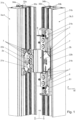
Fig. 1 shows a hinge arrangement in an open position depicting fragments of the profiles of a frame and sash in an axonometric view; -
Fig. 2 shows a method of fastening a hinge member to a profile frame element in an axonometric exploded view; -
Fig. 3 shows the hinge arrangement in an open position depicting fragments of profiles of a frame and sash in a cross-section along the plane perpendicular relative to the axis of the hinge; and -
Fig. 4 shows the hinge arrangement in the closed position depicting fragments of profiles of a frame and sash in a cross-section along the plane perpendicular relative to the axis of the hinge. -
Figs. 1-4 show one of a number ofhinge arrangements 1 that in this embodiment serve to hinge multi-chamber thermalinsulating profile elements 3a of asash 4 of an external door of a building construction partition, wherein the door are not shown on the drawings, on multi-chamber thermalinsulating profile elements 3b of aframe 5. Uniform or multi-chamber glazing units, panes or elements made of tempered glass, plastic, wood, etc., that are not shown in the drawing, can be embedded within the contour defined by the joinedprofile elements 3a of thesash 4. In this embodiment, thehinge arrangement 1 has a form of a pin hinge and comprises ahinge member 2b on the side of theframe 5 connected in a hinged manner via a hinge pin 8 to ahinge member 2a on the side of thesash 4. Where appropriate, numerical references of elements having the same functionality but slightly different constructions were provided with the suffix "a" in the case of thesash 4 or "b" in the case of theframe 5. - As shown in
Fig. 1 , the orientation of the coordinate system used in this description relates to theprofile element 3b of theframe 5 and theprofile element 3a of thesash 4 in the closed position of thehinge arrangement 1. The axis z is parallel to the profile element 3 and it constitutes the axis of the hinge pin 8, the axis y is perpendicular to the plane of the building partition, and the axis x is perpendicular to the axes y and z. The terms "exterior" side (Z) and "interior" side (W) of a building partition relate to the side of a lower temperature (Z) and to the side of a greater temperature (W) respectively. In the presented embodiment, the hinge pin 8 is located on the exterior side (Z). - In this embodiment, the
profile element 3a of thesash 5 comprises an inneraluminum box profile 31a and an outeraluminum box profile 32a, which are connected to each other by means of two longitudinal shapedthermal insulating ribs 33a made of polyamide PA66 comprising 50% of a glass fiber addition. The thermalinsulating ribs 33a define a thermalinsulating space 34a between them. Theprofile element 3b of theframe 4 has in this embodiment an analogous structure defined by an inner firstaluminum box profile 31b and an outeraluminum box profile 32b, connected by thermalinsulating ribs 33b defining a thermalinsulating space 34b. The low thermal conductivity (of less than 0.1 W/(m•K)) of the thermal insulating ribs 33 ensures a thermal separation of the box profiles 31, 32 (whose thermal conductivity amounts about 200 W/(m•K)) in the area of the inner thermal insulating space 34. Thus, the total thermal resistance of the profile elements 3 is relatively high. - The
hinge member 2a on the side of thesash 4 comprises ahinge lever 21a and an adjustingelement 22a fastened by means of fourmounting screws 7 to theprofile element 3a of thesash 4. Thehinge lever 21a is fastened by means of twomounting screws 7 passed through the adjustingelement 22a into theprofile element 3a of thesash 4. Thehinge member 2b on the side of theframe 5 comprises twohinge levers 21b and an adjustingelement 22b fastened by means of fourmounting screws 7 passed throughmounting openings 35 into theprofile element 3b of theframe 5. Each of thehinge levers 21b is fastened by means of twomounting screws 7 passed through the adjustingelement 22b and themounting openings 35 into theprofile element 3b of theframe 5. - As shown in
Fig. 2 , thehinge member 2b is in this embodiment surrounded from the interior side W and from the axis z of the hinge pin 8 by ashaped sealing element 6 made of plastic. Thesealing element 6 is a C-shaped strip made of neoprene foam with a substantially U-shaped form and is fastened between the adjustingelement 22b and theprofile element 3b of theframe 4. For this purpose, the sealingelement 6 is provided with a plurality of mountingprotrusions 62 arranged around its periphery and inserted into the mounting recesses 23 (cf.Fig. 4 ) in the adjustingelement 22b. - As shown in
Figs. 3 and 4 , the height H of thesealing element 6 is greater than the width h of thegap 36 between adjacent thermalinsulating profile elements Fig. 4 ), thesealing element 6 is pressed by the thermalinsulating element 3a of thesash 4. - The
edge 61 of thesealing element 6 that is distant from thehinge member 2b, is bent towards the exterior side Z and towards the axis of the hinge pin 8. Thebent edge 61 generates the preload and ensures that in the closed position of thehinge arrangement 1, the pressure of the air blowing from the exterior side Z into thegap 36 between the thermalinsulating elements bent edge 61 and this air is unable to flow further. - Furthermore, the
outer edge 63 of thesealing element 6 is flush with the surface of theouter box profiles - In other embodiments of the invention that are not presented on the drawings, both
hinge members sealing elements 6, theouter edges 61 of which would be pressed in the closed position of thehinge arrangement 1. - The figures are not necessarily to scale and some features may be exaggerated or minimized in order to better illustrate the present invention. The above embodiments of the present invention are therefore merely exemplary. These and other factors however should not be considered as limiting the spirit of the invention, the intended scope of protection of which is indicated in appended claims.
-
- 1.
- hinge arrangement
- 2.
- hinge
member
21. hinge lever (21a, 21b)
22. adjusting element (22a, 22b)
23. mounting recess - 3.
- thermal insulating profile element
31. inner box profile
32. outer box profile
33. thermal insulating rib
34. thermal insulating space
35. mounting opening
36. gap - 4.
- frame
- 5.
- sash
- 6.
- sealing element
61. distant edge
62. mounting protrusion
63. outer edge - 7.
- mounting screw
- 8.
- hinge pin
Claims (6)
- Thermally insulated hinge arrangement (1), and in particular a door or window hinge arrangement, comprising at least two hinge members (2) connected to each other in an articulated manner by means of a common hinge pin (8) and fastened to thermal insulating profile elements (3) of a frame (4) and a sash (5), wherein the frame (4) defines an interior side (W) and an exterior side (Z) of the hinge arrangement (1) and in the closed position of the hinge arrangement (1) a gap of a non-zero width (h) is defined between adjacent thermal insulating profile elements (3), characterized in that , the hinge arrangement (1) comprises at least one sealing element (6) made of plastic and arranged between at least one hinge member (2b) and a thermal insulating profile element (3) corresponding to the at least one hinge member (2b) and surrounding this hinge member (2b) from the interior side (W) and from the sides by which the straight lines parallel to the axis (z) of the hinge pin (8) are passed through, wherein the height (H) of the at least one sealing element (6) is greater that the width (h) of the gap, and wherein an edge (61) of the at least one sealing element (6) that is distant from the hinge member (2b) is pressed in the closed position of the hinge arrangement (1).
- A hinge arrangement (1) according to Claim 1, characterized in that , the distant edge (61) of the sealing element (6) is bent in the direction of the hinge member (2b) surrounded by this sealing element (6).
- A hinge arrangement (1) according to Claim 1 or 2, characterized in that , the distant edge (61) of the sealing element (6) is pressed in the closed position of the hinge arrangement (1) by the thermal insulating profile element (3) that is adjacent relative to the thermal insulating profile element (3) to which the sealing element (6) is fastened.
- A hinge arrangement (1) according to any one of the preceding Claims, characterized in that , an outer edge (63) of the sealing element (6) is flush with the surfaces of the thermal insulating profile elements (3) from the exterior side (Z).
- A hinge arrangement (1) according to any one of the preceding Claims, characterized in that , the sealing element (6) has a form of a circumferential element.
- A hinge arrangement (1) according to any one of the preceding Claims, characterized in that , the sealing element (6) is made of an elastomer plastic.
Priority Applications (1)
| Application Number | Priority Date | Filing Date | Title |
|---|---|---|---|
| SI202330058T SI4296458T1 (en) | 2022-06-22 | 2023-06-21 | Thermally insulated hinge arrangement |
Applications Claiming Priority (1)
| Application Number | Priority Date | Filing Date | Title |
|---|---|---|---|
| PL441522A PL441522A1 (en) | 2022-06-22 | 2022-06-22 | Thermal insulated hinged system |
Publications (2)
| Publication Number | Publication Date |
|---|---|
| EP4296458A1 true EP4296458A1 (en) | 2023-12-27 |
| EP4296458B1 EP4296458B1 (en) | 2025-10-15 |
Family
ID=86942807
Family Applications (1)
| Application Number | Title | Priority Date | Filing Date |
|---|---|---|---|
| EP23180631.6A Active EP4296458B1 (en) | 2022-06-22 | 2023-06-21 | Thermally insulated hinge arrangement |
Country Status (5)
| Country | Link |
|---|---|
| EP (1) | EP4296458B1 (en) |
| ES (1) | ES3053842T3 (en) |
| PL (1) | PL441522A1 (en) |
| PT (1) | PT4296458T (en) |
| SI (1) | SI4296458T1 (en) |
Citations (10)
| Publication number | Priority date | Publication date | Assignee | Title |
|---|---|---|---|---|
| DE29712633U1 (en) | 1997-07-17 | 1997-09-18 | Schüco International KG, 33609 Bielefeld | Stop seal for windows, doors or facades |
| JPH1054173A (en) * | 1996-08-09 | 1998-02-24 | Goal Co Ltd | Device for preventing finger from being caught in door |
| JPH1088893A (en) * | 1996-09-10 | 1998-04-07 | Takahashi Kanamono Kk | Hinge |
| EP1022425B1 (en) | 1999-01-13 | 2004-01-07 | Dr. Hahn GmbH & Co. KG | Hinge arrangement for doors, windows or similar |
| EP1582674A2 (en) | 2004-03-31 | 2005-10-05 | Carl Fuhr GmbH & Co. KG | Rebate hinge with sealing strip |
| WO2006128549A1 (en) | 2005-05-31 | 2006-12-07 | Dr. Hahn Gmbh & Co. Kg | Hinge system |
| CN205531880U (en) | 2016-02-04 | 2016-08-31 | 嘉寓门窗幕墙(临邑)有限公司 | Hinge seal part and hinge and door and window that have seal structure |
| CN106522753A (en) | 2016-12-19 | 2017-03-22 | 天津东方海川门窗幕墙工程有限公司 | Internal casement screen window and heat insulation internal casement screen window integrated structure |
| KR20170114716A (en) | 2016-04-06 | 2017-10-16 | (주)폴딩테크원 | Door with the multi-block structure sealing device |
| KR200489879Y1 (en) * | 2017-08-17 | 2019-08-23 | 최범식 | A Hinge for Windbreak |
Family Cites Families (2)
| Publication number | Priority date | Publication date | Assignee | Title |
|---|---|---|---|---|
| DE202008014611U1 (en) * | 2008-11-04 | 2010-03-25 | Dr. Hahn Gmbh & Co. Kg | Band assembly for hinged about a hinge axis connection of a wing with a frame |
| GB2511164B (en) * | 2012-12-06 | 2017-08-02 | Era Home Security Ltd | Sash sealing system and method |
-
2022
- 2022-06-22 PL PL441522A patent/PL441522A1/en unknown
-
2023
- 2023-06-21 PT PT231806316T patent/PT4296458T/en unknown
- 2023-06-21 EP EP23180631.6A patent/EP4296458B1/en active Active
- 2023-06-21 ES ES23180631T patent/ES3053842T3/en active Active
- 2023-06-21 SI SI202330058T patent/SI4296458T1/en unknown
Patent Citations (10)
| Publication number | Priority date | Publication date | Assignee | Title |
|---|---|---|---|---|
| JPH1054173A (en) * | 1996-08-09 | 1998-02-24 | Goal Co Ltd | Device for preventing finger from being caught in door |
| JPH1088893A (en) * | 1996-09-10 | 1998-04-07 | Takahashi Kanamono Kk | Hinge |
| DE29712633U1 (en) | 1997-07-17 | 1997-09-18 | Schüco International KG, 33609 Bielefeld | Stop seal for windows, doors or facades |
| EP1022425B1 (en) | 1999-01-13 | 2004-01-07 | Dr. Hahn GmbH & Co. KG | Hinge arrangement for doors, windows or similar |
| EP1582674A2 (en) | 2004-03-31 | 2005-10-05 | Carl Fuhr GmbH & Co. KG | Rebate hinge with sealing strip |
| WO2006128549A1 (en) | 2005-05-31 | 2006-12-07 | Dr. Hahn Gmbh & Co. Kg | Hinge system |
| CN205531880U (en) | 2016-02-04 | 2016-08-31 | 嘉寓门窗幕墙(临邑)有限公司 | Hinge seal part and hinge and door and window that have seal structure |
| KR20170114716A (en) | 2016-04-06 | 2017-10-16 | (주)폴딩테크원 | Door with the multi-block structure sealing device |
| CN106522753A (en) | 2016-12-19 | 2017-03-22 | 天津东方海川门窗幕墙工程有限公司 | Internal casement screen window and heat insulation internal casement screen window integrated structure |
| KR200489879Y1 (en) * | 2017-08-17 | 2019-08-23 | 최범식 | A Hinge for Windbreak |
Also Published As
| Publication number | Publication date |
|---|---|
| ES3053842T3 (en) | 2026-01-27 |
| EP4296458B1 (en) | 2025-10-15 |
| PL441522A1 (en) | 2023-12-27 |
| PT4296458T (en) | 2025-12-05 |
| SI4296458T1 (en) | 2026-01-30 |
Similar Documents
| Publication | Publication Date | Title |
|---|---|---|
| US12320184B2 (en) | Frame solution for laminated VIG unit | |
| EP3447228A1 (en) | Thermal compensation spacer | |
| EP3339550B1 (en) | Aluminium carpentry system having improved thermal insulation | |
| EP4296458A1 (en) | Thermally insulated hinge arrangement | |
| DK160158B (en) | FAN FOR A WINDOW | |
| KR102535898B1 (en) | Heat insulation door assembly | |
| EP3121361B1 (en) | Covering strip | |
| US12123252B2 (en) | Thermal insulation structure in side section in which two-side supporting frame window sash overlaps door frame in sliding window system | |
| CN119156481A (en) | Composite profile assembly for a door, window or facade element and door, window or facade element | |
| KR20240053517A (en) | Heat insulation door assembly | |
| GB2576199A (en) | Elongate member for window or door or frame therefor and reinforcement member for window or door profile | |
| EP2472046A1 (en) | Window or door structure made from an assembly of profiles | |
| ITPI20000019A1 (en) | THERMAL CUT GLASS WINDOW FRAME. |
Legal Events
| Date | Code | Title | Description |
|---|---|---|---|
| PUAI | Public reference made under article 153(3) epc to a published international application that has entered the european phase |
Free format text: ORIGINAL CODE: 0009012 |
|
| STAA | Information on the status of an ep patent application or granted ep patent |
Free format text: STATUS: THE APPLICATION HAS BEEN PUBLISHED |
|
| AK | Designated contracting states |
Kind code of ref document: A1 Designated state(s): AL AT BE BG CH CY CZ DE DK EE ES FI FR GB GR HR HU IE IS IT LI LT LU LV MC ME MK MT NL NO PL PT RO RS SE SI SK SM TR |
|
| STAA | Information on the status of an ep patent application or granted ep patent |
Free format text: STATUS: REQUEST FOR EXAMINATION WAS MADE |
|
| 17P | Request for examination filed |
Effective date: 20240627 |
|
| RBV | Designated contracting states (corrected) |
Designated state(s): AL AT BE BG CH CY CZ DE DK EE ES FI FR GB GR HR HU IE IS IT LI LT LU LV MC ME MK MT NL NO PL PT RO RS SE SI SK SM TR |
|
| STAA | Information on the status of an ep patent application or granted ep patent |
Free format text: STATUS: EXAMINATION IS IN PROGRESS |
|
| 17Q | First examination report despatched |
Effective date: 20241118 |
|
| GRAP | Despatch of communication of intention to grant a patent |
Free format text: ORIGINAL CODE: EPIDOSNIGR1 |
|
| STAA | Information on the status of an ep patent application or granted ep patent |
Free format text: STATUS: GRANT OF PATENT IS INTENDED |
|
| INTG | Intention to grant announced |
Effective date: 20250509 |
|
| GRAS | Grant fee paid |
Free format text: ORIGINAL CODE: EPIDOSNIGR3 |
|
| GRAA | (expected) grant |
Free format text: ORIGINAL CODE: 0009210 |
|
| STAA | Information on the status of an ep patent application or granted ep patent |
Free format text: STATUS: THE PATENT HAS BEEN GRANTED |
|
| AK | Designated contracting states |
Kind code of ref document: B1 Designated state(s): AL AT BE BG CH CY CZ DE DK EE ES FI FR GB GR HR HU IE IS IT LI LT LU LV MC ME MK MT NL NO PL PT RO RS SE SI SK SM TR |
|
| REG | Reference to a national code |
Ref country code: GB Ref legal event code: FG4D Ref country code: CH Ref legal event code: F10 Free format text: ST27 STATUS EVENT CODE: U-0-0-F10-F00 (AS PROVIDED BY THE NATIONAL OFFICE) Effective date: 20251015 |
|
| REG | Reference to a national code |
Ref country code: IE Ref legal event code: FG4D |
|
| REG | Reference to a national code |
Ref country code: DE Ref legal event code: R096 Ref document number: 602023007472 Country of ref document: DE |
|
| REG | Reference to a national code |
Ref country code: NL Ref legal event code: FP |
|
| REG | Reference to a national code |
Ref country code: PT Ref legal event code: SC4A Ref document number: 4296458 Country of ref document: PT Date of ref document: 20251205 Kind code of ref document: T Free format text: AVAILABILITY OF NATIONAL TRANSLATION Effective date: 20251128 |
|
| REG | Reference to a national code |
Ref country code: SK Ref legal event code: T3 Ref document number: E 47447 Country of ref document: SK |
|
| REG | Reference to a national code |
Ref country code: GR Ref legal event code: EP Ref document number: 20250402419 Country of ref document: GR Effective date: 20260115 |
|
| P01 | Opt-out of the competence of the unified patent court (upc) registered |
Free format text: CASE NUMBER: UPC_APP_0017702_4296458/2025 Effective date: 20251216 |
|
| REG | Reference to a national code |
Ref country code: ES Ref legal event code: FG2A Ref document number: 3053842 Country of ref document: ES Kind code of ref document: T3 Effective date: 20260127 |
|
| REG | Reference to a national code |
Ref country code: AT Ref legal event code: MK05 Ref document number: 1847089 Country of ref document: AT Kind code of ref document: T Effective date: 20251015 |
|
| REG | Reference to a national code |
Ref country code: LT Ref legal event code: MG9D |
|
| PG25 | Lapsed in a contracting state [announced via postgrant information from national office to epo] |
Ref country code: NO Free format text: LAPSE BECAUSE OF FAILURE TO SUBMIT A TRANSLATION OF THE DESCRIPTION OR TO PAY THE FEE WITHIN THE PRESCRIBED TIME-LIMIT Effective date: 20260115 |
|
| PG25 | Lapsed in a contracting state [announced via postgrant information from national office to epo] |
Ref country code: AT Free format text: LAPSE BECAUSE OF FAILURE TO SUBMIT A TRANSLATION OF THE DESCRIPTION OR TO PAY THE FEE WITHIN THE PRESCRIBED TIME-LIMIT Effective date: 20251015 Ref country code: HR Free format text: LAPSE BECAUSE OF FAILURE TO SUBMIT A TRANSLATION OF THE DESCRIPTION OR TO PAY THE FEE WITHIN THE PRESCRIBED TIME-LIMIT Effective date: 20251015 Ref country code: FI Free format text: LAPSE BECAUSE OF FAILURE TO SUBMIT A TRANSLATION OF THE DESCRIPTION OR TO PAY THE FEE WITHIN THE PRESCRIBED TIME-LIMIT Effective date: 20251015 |
|
| PG25 | Lapsed in a contracting state [announced via postgrant information from national office to epo] |
Ref country code: RS Free format text: LAPSE BECAUSE OF FAILURE TO SUBMIT A TRANSLATION OF THE DESCRIPTION OR TO PAY THE FEE WITHIN THE PRESCRIBED TIME-LIMIT Effective date: 20260115 |
|
| PG25 | Lapsed in a contracting state [announced via postgrant information from national office to epo] |
Ref country code: IS Free format text: LAPSE BECAUSE OF FAILURE TO SUBMIT A TRANSLATION OF THE DESCRIPTION OR TO PAY THE FEE WITHIN THE PRESCRIBED TIME-LIMIT Effective date: 20260215 |
|
| PG25 | Lapsed in a contracting state [announced via postgrant information from national office to epo] |
Ref country code: PL Free format text: LAPSE BECAUSE OF FAILURE TO SUBMIT A TRANSLATION OF THE DESCRIPTION OR TO PAY THE FEE WITHIN THE PRESCRIBED TIME-LIMIT Effective date: 20251015 |
|
| PG25 | Lapsed in a contracting state [announced via postgrant information from national office to epo] |
Ref country code: LV Free format text: LAPSE BECAUSE OF FAILURE TO SUBMIT A TRANSLATION OF THE DESCRIPTION OR TO PAY THE FEE WITHIN THE PRESCRIBED TIME-LIMIT Effective date: 20251015 |