EP4295767A1 - Schaltungsgehäuse für eine tragbare intraorale anwendung - Google Patents
Schaltungsgehäuse für eine tragbare intraorale anwendung Download PDFInfo
- Publication number
- EP4295767A1 EP4295767A1 EP22180128.5A EP22180128A EP4295767A1 EP 4295767 A1 EP4295767 A1 EP 4295767A1 EP 22180128 A EP22180128 A EP 22180128A EP 4295767 A1 EP4295767 A1 EP 4295767A1
- Authority
- EP
- European Patent Office
- Prior art keywords
- circuit
- sensor
- circuit housing
- housing
- electronic circuit
- Prior art date
- Legal status (The legal status is an assumption and is not a legal conclusion. Google has not performed a legal analysis and makes no representation as to the accuracy of the status listed.)
- Granted
Links
Images
Classifications
-
- A—HUMAN NECESSITIES
- A61—MEDICAL OR VETERINARY SCIENCE; HYGIENE
- A61B—DIAGNOSIS; SURGERY; IDENTIFICATION
- A61B5/00—Measuring for diagnostic purposes; Identification of persons
- A61B5/145—Measuring characteristics of blood in vivo, e.g. gas concentration or pH-value ; Measuring characteristics of body fluids or tissues, e.g. interstitial fluid or cerebral tissue
- A61B5/14507—Measuring characteristics of blood in vivo, e.g. gas concentration or pH-value ; Measuring characteristics of body fluids or tissues, e.g. interstitial fluid or cerebral tissue specially adapted for measuring characteristics of body fluids other than blood
-
- H—ELECTRICITY
- H05—ELECTRIC TECHNIQUES NOT OTHERWISE PROVIDED FOR
- H05K—PRINTED CIRCUITS; CASINGS OR CONSTRUCTIONAL DETAILS OF ELECTRIC APPARATUS; MANUFACTURE OF ASSEMBLAGES OF ELECTRICAL COMPONENTS
- H05K5/00—Casings, cabinets or drawers for electric apparatus
- H05K5/06—Hermetically-sealed casings
-
- A—HUMAN NECESSITIES
- A61—MEDICAL OR VETERINARY SCIENCE; HYGIENE
- A61B—DIAGNOSIS; SURGERY; IDENTIFICATION
- A61B5/00—Measuring for diagnostic purposes; Identification of persons
- A61B5/0002—Remote monitoring of patients using telemetry, e.g. transmission of vital signals via a communication network
-
- A—HUMAN NECESSITIES
- A61—MEDICAL OR VETERINARY SCIENCE; HYGIENE
- A61B—DIAGNOSIS; SURGERY; IDENTIFICATION
- A61B5/00—Measuring for diagnostic purposes; Identification of persons
- A61B5/145—Measuring characteristics of blood in vivo, e.g. gas concentration or pH-value ; Measuring characteristics of body fluids or tissues, e.g. interstitial fluid or cerebral tissue
- A61B5/14546—Measuring characteristics of blood in vivo, e.g. gas concentration or pH-value ; Measuring characteristics of body fluids or tissues, e.g. interstitial fluid or cerebral tissue for measuring analytes not otherwise provided for, e.g. ions, cytochromes
-
- A—HUMAN NECESSITIES
- A61—MEDICAL OR VETERINARY SCIENCE; HYGIENE
- A61B—DIAGNOSIS; SURGERY; IDENTIFICATION
- A61B5/00—Measuring for diagnostic purposes; Identification of persons
- A61B5/68—Arrangements of detecting, measuring or recording means, e.g. sensors, in relation to patient
- A61B5/6801—Arrangements of detecting, measuring or recording means, e.g. sensors, in relation to patient specially adapted to be attached to or worn on the body surface
- A61B5/6813—Specially adapted to be attached to a specific body part
- A61B5/6814—Head
- A61B5/682—Mouth, e.g., oral cavity; tongue; Lips; Teeth
-
- A—HUMAN NECESSITIES
- A61—MEDICAL OR VETERINARY SCIENCE; HYGIENE
- A61C—DENTISTRY; APPARATUS OR METHODS FOR ORAL OR DENTAL HYGIENE
- A61C19/00—Dental auxiliary appliances
- A61C19/02—Protective casings, e.g. boxes for instruments; Bags
-
- A—HUMAN NECESSITIES
- A61—MEDICAL OR VETERINARY SCIENCE; HYGIENE
- A61B—DIAGNOSIS; SURGERY; IDENTIFICATION
- A61B2560/00—Constructional details of operational features of apparatus; Accessories for medical measuring apparatus
- A61B2560/02—Operational features
- A61B2560/0204—Operational features of power management
- A61B2560/0214—Operational features of power management of power generation or supply
-
- A—HUMAN NECESSITIES
- A61—MEDICAL OR VETERINARY SCIENCE; HYGIENE
- A61B—DIAGNOSIS; SURGERY; IDENTIFICATION
- A61B2560/00—Constructional details of operational features of apparatus; Accessories for medical measuring apparatus
- A61B2560/02—Operational features
- A61B2560/0242—Operational features adapted to measure environmental factors, e.g. temperature, pollution
- A61B2560/0247—Operational features adapted to measure environmental factors, e.g. temperature, pollution for compensation or correction of the measured physiological value
- A61B2560/0257—Operational features adapted to measure environmental factors, e.g. temperature, pollution for compensation or correction of the measured physiological value using atmospheric pressure
-
- A—HUMAN NECESSITIES
- A61—MEDICAL OR VETERINARY SCIENCE; HYGIENE
- A61B—DIAGNOSIS; SURGERY; IDENTIFICATION
- A61B2560/00—Constructional details of operational features of apparatus; Accessories for medical measuring apparatus
- A61B2560/04—Constructional details of apparatus
- A61B2560/0406—Constructional details of apparatus specially shaped apparatus housings
-
- A—HUMAN NECESSITIES
- A61—MEDICAL OR VETERINARY SCIENCE; HYGIENE
- A61B—DIAGNOSIS; SURGERY; IDENTIFICATION
- A61B2562/00—Details of sensors; Constructional details of sensor housings or probes; Accessories for sensors
- A61B2562/02—Details of sensors specially adapted for in-vivo measurements
- A61B2562/0219—Inertial sensors, e.g. accelerometers, gyroscopes, tilt switches
-
- A—HUMAN NECESSITIES
- A61—MEDICAL OR VETERINARY SCIENCE; HYGIENE
- A61B—DIAGNOSIS; SURGERY; IDENTIFICATION
- A61B2562/00—Details of sensors; Constructional details of sensor housings or probes; Accessories for sensors
- A61B2562/02—Details of sensors specially adapted for in-vivo measurements
- A61B2562/029—Humidity sensors
-
- A—HUMAN NECESSITIES
- A61—MEDICAL OR VETERINARY SCIENCE; HYGIENE
- A61B—DIAGNOSIS; SURGERY; IDENTIFICATION
- A61B2562/00—Details of sensors; Constructional details of sensor housings or probes; Accessories for sensors
- A61B2562/16—Details of sensor housings or probes; Details of structural supports for sensors
-
- A—HUMAN NECESSITIES
- A61—MEDICAL OR VETERINARY SCIENCE; HYGIENE
- A61B—DIAGNOSIS; SURGERY; IDENTIFICATION
- A61B2562/00—Details of sensors; Constructional details of sensor housings or probes; Accessories for sensors
- A61B2562/16—Details of sensor housings or probes; Details of structural supports for sensors
- A61B2562/164—Details of sensor housings or probes; Details of structural supports for sensors the sensor is mounted in or on a conformable substrate or carrier
-
- A—HUMAN NECESSITIES
- A61—MEDICAL OR VETERINARY SCIENCE; HYGIENE
- A61B—DIAGNOSIS; SURGERY; IDENTIFICATION
- A61B5/00—Measuring for diagnostic purposes; Identification of persons
- A61B5/01—Measuring temperature of body parts ; Diagnostic temperature sensing, e.g. for malignant or inflamed tissue
-
- A—HUMAN NECESSITIES
- A61—MEDICAL OR VETERINARY SCIENCE; HYGIENE
- A61B—DIAGNOSIS; SURGERY; IDENTIFICATION
- A61B5/00—Measuring for diagnostic purposes; Identification of persons
- A61B5/03—Measuring fluid pressure within the body other than blood pressure, e.g. cerebral pressure ; Measuring pressure in body tissues or organs
- A61B5/036—Measuring fluid pressure within the body other than blood pressure, e.g. cerebral pressure ; Measuring pressure in body tissues or organs by means introduced into body tracts
- A61B5/038—Measuring oral pressure
-
- A—HUMAN NECESSITIES
- A61—MEDICAL OR VETERINARY SCIENCE; HYGIENE
- A61B—DIAGNOSIS; SURGERY; IDENTIFICATION
- A61B5/00—Measuring for diagnostic purposes; Identification of persons
- A61B5/145—Measuring characteristics of blood in vivo, e.g. gas concentration or pH-value ; Measuring characteristics of body fluids or tissues, e.g. interstitial fluid or cerebral tissue
- A61B5/14532—Measuring characteristics of blood in vivo, e.g. gas concentration or pH-value ; Measuring characteristics of body fluids or tissues, e.g. interstitial fluid or cerebral tissue for measuring glucose, e.g. by tissue impedance measurement
-
- A—HUMAN NECESSITIES
- A61—MEDICAL OR VETERINARY SCIENCE; HYGIENE
- A61B—DIAGNOSIS; SURGERY; IDENTIFICATION
- A61B5/00—Measuring for diagnostic purposes; Identification of persons
- A61B5/145—Measuring characteristics of blood in vivo, e.g. gas concentration or pH-value ; Measuring characteristics of body fluids or tissues, e.g. interstitial fluid or cerebral tissue
- A61B5/14539—Measuring characteristics of blood in vivo, e.g. gas concentration or pH-value ; Measuring characteristics of body fluids or tissues, e.g. interstitial fluid or cerebral tissue for measuring pH
-
- A—HUMAN NECESSITIES
- A61—MEDICAL OR VETERINARY SCIENCE; HYGIENE
- A61B—DIAGNOSIS; SURGERY; IDENTIFICATION
- A61B5/00—Measuring for diagnostic purposes; Identification of persons
- A61B5/42—Detecting, measuring or recording for evaluating the gastrointestinal, the endocrine or the exocrine systems
- A61B5/4261—Evaluating exocrine secretion production
- A61B5/4277—Evaluating exocrine secretion production saliva secretion
-
- A—HUMAN NECESSITIES
- A61—MEDICAL OR VETERINARY SCIENCE; HYGIENE
- A61B—DIAGNOSIS; SURGERY; IDENTIFICATION
- A61B5/00—Measuring for diagnostic purposes; Identification of persons
- A61B5/48—Other medical applications
- A61B5/4845—Toxicology, e.g. by detection of alcohol, drug or toxic products
Definitions
- the present invention relates to a circuit package for portable intraoral use and a method of manufacturing a circuit package for portable intraoral use.
- the publication US 4,629,424 A relates to an intraoral environmental sensing device comprising a removable oral device with a number of chemically sensitive electrodes and a common reference electrode at the chemical sensing sites.
- a circuit housing for portable intraoral use having an inner layer made of a first material for waterproofing an electronic circuit; and an outer layer made of a second material for spatially adapting the circuit housing to a set of teeth, which at least partially covers the first material.
- the circuit housing achieves the technical advantage that water penetration into the circuit housing due to a chewing movement can be prevented.
- the second layer also serves as mechanical protection against damage to the first layer.
- the circuit housing with two separate layers is more robust and less susceptible to water ingress.
- the circuit housing can protect electronic circuits for the medical and dental sector from external influences such as water, saliva, other liquids or contamination and prevent failure.
- the first material of the inner layer comprises at least one protective lacquer which consists of silicone, (meth)acrylate resin, urethane resin, epoxy resin, parylene or mixtures thereof.
- the second material of the outer layer comprises at least one 3D printable material (for example in stereolithography), in particular light-polymerizable resins, preferably (meth)acrylates, epoxy resins, urethane resins, thermoplastics, and / or the second material a millable material, in particular poly(meth)acrylate, polycarbonate or ceramic.
- the second material may be formed from a material that can be used in a three-dimensional printing process or milling process. This achieves, for example, the technical advantage that the circuit housing can be easily spatially adapted to different intraoral spaces.
- materials for the second material of the outer layer are orthodontic splints (e.g. bite splints) materials such as ProArt Print Splint from Ivoclar Vivadent.
- the second material has a fracture toughness of more than 0.5 MPa m or a flexural modulus of less than 2500 MPa. This achieves, for example, the technical advantage that the second material adapts well to a set of teeth.
- the first and second materials allow transmission of electromagnetic radiation in the range between 2.2 and 2.4 GHz. This makes the technical, for example The advantage is that data can be transmitted through the circuit housing via Bluetooth.
- the first and second materials allow transmission of electromagnetic radiation in the range between 13 and 14 MHz. This achieves, for example, the technical advantage that data can be transmitted through the circuit housing via near field communication (NFC).
- NFC near field communication
- the first and second materials have an electrical conductivity below 10 -10 S/m. This achieves, for example, the technical advantage that leakage currents can be prevented.
- the circuit housing comprises an opening for a sensor. This achieves the technical advantage, for example, that saliva can be brought to the sensor for measurement.
- the circuit housing comprises an electronic circuit with a device with a number of chemical, biological and/or physical sensors.
- Examples include a circuit with one or more pH sensor, a lactate sensor, a temperature sensor, a glucose sensor, a volatile sulfur component sensor, an alcohol sensor, an air pressure sensor, a cortisol sensor, a Osmolality sensor, an ion-selective sensor, an acceleration sensor, a pressure sensor and / or a humidity sensor.
- the circuit housing can also include several sensors. For example, when measuring lactate or pH values, two identical sensors can be used in a circuit to generate measured values at different points or to check the first sensor.
- the circuit housing arrangement comprises the circuit housing and an electronic circuit with a device with a number of chemical, biological and/or physical sensors.
- a circuit with one or more pH sensor, a lactate sensor, a temperature sensor, a glucose sensor, a volatile sulfur component sensor, an alcohol sensor, an air pressure sensor, a cortisol sensor, an osmolality sensor, an ion-selective sensor, an acceleration sensor, a pressure sensor and/or or a humidity sensor.
- the circuit housing arrangement can also include several sensors. For example, when measuring lactate or pH values, two identical sensors can be used in a circuit to generate measured values at different points or to check the first sensor.
- the circuit housing comprises a Electronic circuit with a circuit section for wirelessly transmitting energy, a transmitting/receiving unit for wireless data transmission and/or an energy storage device. This achieves, for example, the technical advantage that energy and/or data can be transmitted to the electronic circuit.
- the circuit housing arrangement comprises the circuit housing and an electronic circuit with a circuit section for wirelessly transmitting energy, a transmitting/receiving unit for wireless data transmission and/or an energy storage device. This achieves, for example, the technical advantage that energy and/or data can be transmitted to the electronic circuit.
- the circuit housing comprises an intermediate layer for connecting the inner layer and the outer layer. This achieves, for example, the technical advantage that the adhesion between the inner and outer layers can be improved or mechanical protection of the inner components is increased.
- the circuit housing comprises an electronic circuit that is cast into the first material. This achieves, for example, the technical advantage that moisture protection is further improved.
- the circuit housing arrangement comprises the circuit housing and an electronic circuit which is cast into the first material. This achieves, for example, the technical advantage that moisture protection is further improved.
- a method of manufacturing a circuit housing for portable intraoral use comprising the steps of arranging an inner layer of a first material for waterproofing an electronic circuit; and arranging an outer layer made of a second material for spatially adapting the circuit housing to a denture, which at least partially covers the first material.
- the electronic circuit is cast into the first material. This achieves, for example, the technical advantage that penetration of moisture is particularly effectively prevented.
- the first material is painted onto the electronic circuit or applied by physical vapor deposition or chemical vapor deposition. This achieves, for example, the technical advantage that the electronic circuit can be enclosed in a particularly waterproof film with a thin film.
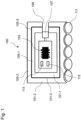
- Fig. 1 shows a schematic illustration of a circuit housing 100 for a portable intraoral electronic circuit 103.
- the circuit housing 100 can be used in a patient's mouth as a wearable device.
- the electronic circuit 103 used within the circuit housing 100 is worn intraorally for a period of several minutes to days.
- the circuit housing 100 protects the electronic circuit 103 from saliva and ingested food or liquid.
- the circuit housing 100 protects the electronic circuit 103 from damage caused by accidental biting.
- the circuit housing 100 thus provides a seal for the electronic circuit 103 from external influences. Materials that are already approved for the intraoral area can be used for sealing. Since the circuit housing 100 in one When worn in the mouth, biocompatible materials can be used. The EN ISO 7405:2019 standard is used to assess the biocompatibility of dental materials.
- the protection of the electronic circuit 103 follows an onion principle.
- the circuit housing 100 includes an inner layer 105-1 made of a biocompatible material 101-1 for waterproofing an electronic circuit 103.
- an outer layer 105-2 made of a biocompatible material 101-2 for spatially adapting the circuit housing to a set of teeth 111.
- the outer layer at least partially covers and surrounds the first material 101-1 of the inner layer 105-1 the first material is 101-1.
- the outer layer 105-2 can be made individually for the patient and can adapt seamlessly to the dentition 111 so that it resists external pressure when teeth are clenched.
- shaping additive or subtractive manufacturing processes are therefore advantageous because they can produce the outer layer 105-1 in the desired spatial shape. Three-dimensional printing or injection molding processes are suitable for this.
- the material 101-1 of the inner layer 105-1 is formed, for example, by a protective lacquer (conformal coating).
- the protective varnish can consist of silicone, (meth)acrylate resin, urethane resin, epoxy resin, parylene or mixtures thereof.
- the material 101-1 of the inner layer 101-5 may also include polyvinylsiloxane.
- materials for the material 101-1 of the inner layer are 105-1 Polyvinylsiloxane impression materials such as those from the Virtual product line from Ivoclar Vivadent Putty, Heavy Body, Monophase, Light Body and Extra Light Body, or (meth)acrylate resins such as Heliobond from Ivoclar Vivadent.
- the inner layer 105-1 should be as thin as possible.
- the inner layer 105-1 for example, has a minimum thickness of preferably 5 mm to 0.0001 mm, most preferably 3 mm to 0.001, particularly preferably 1 mm to 0.01 mm.
- the inner layer 105-1 for example, has a maximum thickness of preferably 10 mm to 0.0001 mm, most preferably 6 mm to 0.001, particularly preferably 2 mm to 0.01 mm.
- the outer layer 105-2 for example, has a minimum thickness of preferably 15 mm to 0.1 mm, most preferably 12 mm to 0.5 mm, particularly preferably 10 mm to 1 mm.
- the outer layer 105-2 for example, has a maximum thickness of preferably 30 mm to 0.1 mm, most preferably 20 mm to 0.5 mm, particularly preferably 15 mm to 1 mm.
- the material 101-2 of the outer layer 105-2 includes a material that can be used in a three-dimensional printing process, such as a radical polymerizable composition or a photopolymerizable resin for stereolithography.
- the material 101-2 of the outer layer 105-2 may comprise at least one 3D printable material, in particular light-polymerizable resins, preferably (meth)acrylates, epoxy resins, urethane resins, and/or thermoplastics.
- the second material 101-2 may also include a millable material, in particular poly(meth)acrylate, polycarbonate or ceramic.
- the circuit housing 100 may also have an intermediate layer 101-3 as a bonding material between the inner layer 101-1 and the outer layer 101-2 include.
- the material 105-3 of the intermediate layer 101-3 serves as a binding material and is a potting material or potting material, such as silicone, urethane resin, epoxy resin or (meth)acrylate resin.
- the electronic circuit 103 includes a transmitting/receiving unit 113 for wireless data transmission, such as a communication unit for wireless data transmission such as Bluetooth in one or NFC.
- a transmitting/receiving unit 113 for wireless data transmission such as a communication unit for wireless data transmission such as Bluetooth in one or NFC.
- the materials 101-1, 1012 and 101-3 of the circuit housing 100 are suitable for electromagnetic radiation in the range between 2.2 and 2.4 GHz (Bluetooth) or in the range between 13 and 14 MHz (NFC). permeable.
- the electronic circuit 103 can include a wirelessly rechargeable battery as an energy storage device 115.
- the electronic circuit 103 has a circuit section for wirelessly transmitting energy, for example with an induction loop.
- the materials used 101-1, 101-2 and 101-3 therefore allow wireless charging and communication via Bluetooth or NFC.
- the circuit housing 100 may contain electrical outputs or lines for different sensors 107 of the electronic circuit 103.
- the sensors 107 are used, for example, to determine the amount of various substances, such as lactate, glucose, cortisol, alcohol or volatile sulfur components (Volatile Sulfur Compounds - VSC).
- the sensors 107 can also be provided for measuring a pH value, a temperature, an air pressure or an osmolality.
- the sensors 107 are in direct contact with the saliva. Depending on the application, the sensors 107 are not covered so that saliva or air can come into contact with the sensor 107.
- the circuit housing 100 includes at least one opening 109, which extends through the layers 101-1, 101-2 and 101-3 and brings the liquid to the sensor 107.
- the openings 109 of the different sensors 107 can differ in shape, size and position and can be adapted to the individual circuit housing 100 of the carrier.
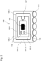
- Fig. 2 shows a schematic illustration of a circuit housing 100 in a second embodiment.
- the inner layer 105-1, the intermediate layer 105-3 and the outer layer 105-2 are constructed completely closed around the electronic circuit 103.
- the circuit housing 100 therefore has no opening 109.
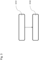
- Fig. 3 shows a block diagram of a method for manufacturing a circuit package 100 for portable intraoral use.
- a first step S101 an inner layer of the first material 101-1 is arranged for waterproofing the electronic circuit 103.
- the electronic circuit 103 is, for example, cast in silicone or another material to keep it waterproof. This casing forms the first protective layer to protect the electronic circuit 103.
- the outer layer is made of the second material 101-2 for spatial adjustment of the Circuit housing is arranged on the teeth 111, which at least partially covers the first material 101-1.
- the inner layer can, for example, be painted on.
- the inner layer 105-1 is preferably not printed, but rather by encapsulation such as potting, potting, dip coating, spray coating, brush coating, physical vapor deposition (PVD). ) or chemical vapor deposition (Chemical Vapor Deposition - CVD) is applied to the electronic circuit 103.
- the inner layer 105-1 can be cured thermally, chemically or by UV radiation or air drying. These methods are easy to handle and the electronic circuit 103 can be protected with a thin film as the inner layer 101-1.
- the electronic circuit 103 can be partially or completely sealed as required.
- the electronic circuit 103 can also be immersed in the material 101-1 or painted or coated with it. After the material 101-1 has hardened, the electronic circuit 103 is surrounded by a protective layer. Multiple layers of material 101-1 can also be applied for a seal. After complete sealing, the electronic circuit 103 is sealed in a watertight manner.
- a flexible and connecting intermediate layer 101-3 such as an adhesive, can also be used to connect the inner layer 101-1 to the outer layer 101-2 can be applied.
- the intermediate layer 101-3 also forms further mechanical protection for the underlying layer 101-1 and the electronic circuit.
- the intermediate layer 101-3 can be formed from a third material as a binding material, such as polyvinyl ether or silicone, in particular addition silicone or vinyl polysiloxane.
- the sealed electronic circuit 103 can safely withstand saliva and other liquids in the mouth.
- the materials 101-1, 101-2 and 101-3 can be removed from the electronic circuit 103 if necessary.
- All method steps can be implemented by devices that are suitable for carrying out the respective method step. All functions that are carried out by physical features can be a procedural step of a process.
Landscapes
- Health & Medical Sciences (AREA)
- Life Sciences & Earth Sciences (AREA)
- Engineering & Computer Science (AREA)
- Physics & Mathematics (AREA)
- Animal Behavior & Ethology (AREA)
- Veterinary Medicine (AREA)
- Public Health (AREA)
- General Health & Medical Sciences (AREA)
- Pathology (AREA)
- Medical Informatics (AREA)
- Molecular Biology (AREA)
- Surgery (AREA)
- Heart & Thoracic Surgery (AREA)
- Biomedical Technology (AREA)
- Biophysics (AREA)
- Oral & Maxillofacial Surgery (AREA)
- Dentistry (AREA)
- Computer Networks & Wireless Communication (AREA)
- Optics & Photonics (AREA)
- Microelectronics & Electronic Packaging (AREA)
- Epidemiology (AREA)
- Measuring And Recording Apparatus For Diagnosis (AREA)
- Casings For Electric Apparatus (AREA)
Abstract
Description
- Die vorliegende Erfindung betrifft ein Schaltungsgehäuse für eine tragbare intraorale Anwendung und ein Verfahren zum Herstellen eines Schaltungsgehäuse für eine tragbare intraorale Anwendung.
- Die Druckschrift
US 4,629,424 A betrifft eine Vorrichtung zur intraoralen Umgebungserfassung, die eine abnehmbare orale Vorrichtung mit einer Anzahl von chemisch empfindlichen Elektroden und einer gemeinsamen Referenzelektrode an den chemischen Erfassungsstellen umfasst. - Zurzeit werden elektronische Geräte für einen Intraoralraum durch ein äußeres, separates Gehäuse aus Polymeren geschützt. Neue Materialien erlauben dagegen kleinere Baugrößen von elektronischen Geräten für den dentalen Bereich. Diese Gehäuse werden oft undicht und schützen die innenliegende Elektronik nur unzureichend.
- Es ist die technische Aufgabe der vorliegenden Erfindung, ein Schaltungsgehäuse bereitzustellen, mit dem eine elektronische Schaltung in einem Intraoralraum besser vor Feuchtigkeit geschützt werden kann.
- Diese technische Aufgabe wird durch Gegenstände nach den unabhängigen Ansprüchen gelöst. Technisch vorteilhafte Ausführungsformen sind Gegenstand der abhängigen Ansprüche, der Beschreibung und der Zeichnungen.
- Gemäß einem ersten Aspekt wird die technische Aufgabe durch ein Schaltungsgehäuse für eine tragbare intraorale Anwendung gelöst, mit einer inneren Schicht aus einem ersten Material zum wasserdichten Einschließen einer elektronischen Schaltung; und einer äußeren Schicht aus einem zweiten Material zum räumlichen Anpassen des Schaltungsgehäuses an ein Gebiss, die das erste Material zumindest teilweise abdeckt.
- Durch das Schaltungsgehäuse wird der technische Vorteil erreicht, dass Wassereinbrüche in das Schaltungsgehäuse aufgrund einer Kaubewegung verhindert werden können. Zudem dient die zweite Schicht zum mechanischen Schutz vor Beschädigung der ersten Schicht. Das Schaltungsgehäuse mit zwei separaten Schichten ist robuster und weniger anfällig für Wassereinbrüche. Durch das Schaltungsgehäuse können elektronische Schaltungen für den medizinischen und dentalen Bereich vor äußeren Einflüssen wie Wasser, Speichel, anderen Flüssigkeiten oder Verunreinigungen geschützt werden und ein Ausfall verhindert werden.
- In einer technisch vorteilhaften Ausführungsform des Schaltungsgehäuses umfasst das erste Material der inneren Schicht mindestens einen Schutzlack, der aus Silikon, (Meth)acrylatharz, Urethanharz, Epoxidharz, Parylene oder Mischungen davon besteht. Dadurch wird beispielsweise der technische Vorteil erreicht, dass besonders geeignete Materialien zum wasserdichten Einschließen der elektronischen Schaltung verwendet werden.
- In einer weiteren technisch vorteilhaften Ausführungsform des Schaltungsgehäuses umfasst das zweite Material der äußeren Schicht mindestens ein 3D-druckbares Material (beispielweise bei Stereolithographie), insbesondere lichtpolymerisierbare Harze, vorzugsweise (Meth)acrylate, Epoxidharze, Urethanharze, Thermoplaste, und/oder das zweite Material umfasst ein fräsbares Material, insbesondere Poly(meth)acrylat, Polycarbonat oder Keramik. Das zweite Material kann aus einem aus einem Material gebildet sein, das in einem dreidimensionalen Druckverfahren oder Fräsverfahren verwendet werden kann. Dadurch wird beispielsweise der technische Vorteil erreicht, dass das Schaltungsgehäuse auf einfache Weise räumlich an unterschiedliche Intraoralräume angepasst werden kann.
- In bevorzugten Ausführungsformen, Materialien für das zweite Material der äußeren Schicht sind orthodontische Schienen (z.B. Aufbissschienen) Materialien wie ProArt Print Splint der Firma Ivoclar Vivadent.
- In einer weiteren technisch vorteilhaften Ausführungsform des Schaltungsgehäuses weist das zweite Material eine Bruchzähigkeit von mehr als 0,5

- In einer weiteren technisch vorteilhaften Ausführungsform des Schaltungsgehäuses lässt das erste und das zweite Material eine Transmission elektromagnetischer Strahlung im Bereich zwischen 2,2 und 2,4 GHz zu. Dadurch wird beispielsweise der technische Vorteil erreicht, dass Daten durch das Schaltungsgehäuse hindurch über Bluetooth übermittelt werden können.
- In einer weiteren technisch vorteilhaften Ausführungsform des Schaltungsgehäuses lassen das erste und das zweite Material eine Transmission elektromagnetischer Strahlung im Bereich zwischen 13 und 14 MHz zu. Dadurch wird beispielsweise der technische Vorteil erreicht, dass Daten durch das Schaltungsgehäuse hindurch über Nahfeldkommunikation (Near Field Communication - NFC) übertragen werden können.
- In einer weiteren technisch vorteilhaften Ausführungsform des Schaltungsgehäuses weisen das erste und das zweite Material eine elektrische Leitfähigkeit unter 10-10 S/m auf. Dadurch wird beispielsweise der technische Vorteil erreicht, dass Verlustströme verhindert werden können.
- In einer weiteren technisch vorteilhaften Ausführungsform des Schaltungsgehäuses umfasst das Schaltungsgehäuse eine Öffnung für einen Sensor. Dadurch wird beispielsweise der technische Vorteil erreicht, dass Speichel zur Messung an den Sensor herangeführt werden kann.
- In einer weiteren technisch vorteilhaften Ausführungsform des Schaltungsgehäuses umfasst das Schaltungsgehäuse eine elektronische Schaltung mit einer Vorrichtung mit einer Anzahl von chemisch, biologisch und/oder physikalischen Sensoren. Beispiele sind eine Schaltung mit einem oder mehreren pH-Sensor, einem Laktatsensor, einem Temperatursensor, einem Glukosesensor, einen Sensor für flüchtige Schwefelkomponenten, einem Alkoholsensor, einem Luftdrucksensor, einem Cortisolsensor, einem Osmolalitätssensor, einem ionenselektiven Sensor, einem Beschleunigungssensor, einem Drucksensor und/oder einem Feuchtigkeitssensor. Dadurch wird beispielsweise der technische Vorteil erreicht, dass besonders geeignete Sensoren für einen Intraoralraum verwendet werden. Das Schaltungsgehäuse kann auch mehrere Sensoren umfassen. Es können beispielsweise bei einer Laktat- oder pH-Wertmessung auch zwei gleiche Sensoren in einer Schaltung genutzt werden, um Messwerte an verschiedenen Stellen zu generieren oder zu einer Kontrolle des ersten Sensors.
- In einer technisch vorteilhaften Ausführungsform einer Schaltungsgehäuseanordnung umfasst die Schaltungsgehäuseanordnung das Schaltungsgehäuse und eine elektronische Schaltung mit einer Vorrichtung mit einer Anzahl von chemisch, biologisch und/oder physikalischen Sensoren. Beispiele sind eine Schaltung mit einem oder mehreren pH-Sensor, einem Laktatsensor, einem Temperatursensor, einem Glukosesensor, einen Sensor für flüchtige Schwefelkomponenten, einem Alkoholsensor, einem Luftdrucksensor, einem Cortisolsensor, einem Osmolalitätssensor, einem ionenselektiven Sensor, einem Beschleunigungssensor, einem Drucksensor und/oder einem Feuchtigkeitssensor. Dadurch wird beispielsweise der technische Vorteil erreicht, dass besonders geeignete Sensoren für einen Intraoralraum verwendet werden. Die Schaltungsgehäuseanordnung kann auch mehrere Sensoren umfassen. Es können beispielsweise bei einer Laktat- oder pH-Wertmessung auch zwei gleiche Sensoren in einer Schaltung genutzt werden, um Messwerte an verschiedenen Stellen zu generieren oder zu einer Kontrolle des ersten Sensors.
- In einer weiteren technisch vorteilhaften Ausführungsform des Schaltungsgehäuses umfasst das Schaltungsgehäuse eine elektronische Schaltung mit einem Schaltungsabschnitt zum drahtlosen Übertragen von Energie, eine Sende-/Empfangseinheit für eine drahtlose Datenübertragung und/oder einen Energiespeicher. Dadurch wird beispielsweise der technische Vorteil erreicht, dass Energie und/oder Daten an die elektronische Schaltung übertragen werden können.
- In einer weiteren technisch vorteilhaften Ausführungsform einer Schaltungsgehäuseanordnung umfasst die Schaltungsgehäuseanordnung das Schaltungsgehäuse und eine elektronische Schaltung mit einem Schaltungsabschnitt zum drahtlosen Übertragen von Energie, eine Sende-/Empfangseinheit für eine drahtlose Datenübertragung und/oder einen Energiespeicher. Dadurch wird beispielsweise der technische Vorteil erreicht, dass Energie und/oder Daten an die elektronische Schaltung übertragen werden können.
- In einer weiteren technisch vorteilhaften Ausführungsform des Schaltungsgehäuses umfasst das Schaltungsgehäuse eine Zwischenschicht zum Verbinden der inneren Schicht und der äußeren Schicht. Dadurch wird beispielsweise der technische Vorteil erreicht, dass die Haftung zwischen der inneren und der äußeren Schicht verbessert werden kann oder ein mechanischer Schutz der inneren Komponenten erhöht wird.
- In einer weiteren technisch vorteilhaften Ausführungsform des Schaltungsgehäuses umfasst das Schaltungsgehäuse eine elektronische Schaltung, die in das erste Material eingegossen ist. Dadurch wird beispielsweise der technische Vorteil erreicht, dass ein Feuchtigkeitsschutz weiter verbessert wird.
- In einer weiteren technisch vorteilhaften Ausführungsform einer Schaltungsgehäuseanordnung umfasst die Schaltungsgehäuseanordnung das Schaltungsgehäuse und eine elektronische Schaltung, die in das erste Material eingegossen ist. Dadurch wird beispielsweise der technische Vorteil erreicht, dass ein Feuchtigkeitsschutz weiter verbessert wird.
- Gemäß einem zweiten Aspekt wird die technische Aufgabe durch ein Verfahren zum Herstellen eines Schaltungsgehäuse für eine tragbare intraorale Anwendung gelöst, mit den Schritten eines Anordnens einer inneren Schicht aus einem ersten Material zum wasserdichten Einschließen einer elektronischen Schaltung; und eines Anordnens einer äußeren Schicht aus einem zweiten Material zum räumlichen Anpassen des Schaltungsgehäuses an ein Gebiss, die das erste Material zumindest teilweise abdeckt. Dadurch werden die gleichen technischen Vorteile wie durch das Schaltungsgehäuse nach dem ersten Aspekt erreicht.
- In einer technisch vorteilhaften Ausführungsform des Verfahrens wird die elektronische Schaltung in das erste Material eingegossen. Dadurch wird beispielsweise der technische Vorteil erreicht, dass ein Eindringen von Feuchtigkeit besonders wirksam verhindert wird.
- In einer weiteren technisch vorteilhaften Ausführungsform des Verfahrens wird das erste Material auf die elektronische Schaltung auflackiert oder durch physikalische Gasphasenabscheidung oder chemische Gasphasenabscheidung angebracht. Dadurch wird beispielsweise der technische Vorteil erreicht, dass die elektronische Schaltung mit einem dünnen Film besonders wasserfest eingeschlossen werden kann.
- Ausführungsbeispiele der Erfindung sind in den Zeichnungen dargestellt und werden im Folgenden näher beschrieben.
- Es zeigen:
- Fig. 1
- eine schematische Abbildung eines Schaltungsgehäuses in einer ersten Ausführungsform;
- Fig. 2
- eine schematische Abbildung eines Schaltungsgehäuses in einer zweiten Ausführungsform; und
- Fig. 3
- ein Blockdiagramm eines Verfahrens zum Herstellen eines Schaltungsgehäuses.
-
Fig. 1 zeigt eine schematische Abbildung eines Schaltungsgehäuses 100 für eine tragbare intraorale elektronische Schaltung 103. Das Schaltungsgehäuse 100 kann in einem Mund eines Patienten als tragbare Vorrichtung (Wearable) verwendet werden. - Die verwendete elektronische Schaltung 103 innerhalb des Schaltungsgehäuses 100 wird intraoral über einen Zeitraum von mehreren Minuten bis Tagen getragen. Das Schaltungsgehäuse 100 schützt die elektronische Schaltung 103 hierbei vor dem Speichel und aufgenommener Nahrung oder Flüssigkeit. Zudem schützt das Schaltungsgehäuse 100 die elektronische Schaltung 103 vor einer Beschädigung durch versehentliches Beißen. Das Schaltungsgehäuse 100 stellt somit eine Versiegelung für die elektronische Schaltung 103 vor äußeren Einflüssen bereit. Für die Versiegelung können Materialien verwendet werden, die im intraoralen Bereich bereits zugelassen sind. Da das Schaltungsgehäuse 100 in einem Mund getragen wird, können hierzu biokompatible Materialien verwendet werden. Für die Bewertung der Biokompatibilität von Dentalmaterialien wird die Norm EN ISO 7405:2019 verwendet.
- Der Schutz der elektronischen Schaltung 103 folgt einem Zwiebelprinzip. Das Schaltungsgehäuse 100 umfasst eine innere Schicht 105-1 aus einem biokompatiblen Material 101-1 zum wasserdichten Einschließen einer elektronischen Schaltung 103.
- Auf der inneren Schicht befindet sich eine äußere Schicht 105-2 aus einem biokompatiblen Material 101-2 zum räumlichen Anpassen des Schaltungsgehäuses an ein Gebiss 111. Die äußere Schicht deckt das erste Material 101-1 der inneren Schicht 105-1 zumindest teilweise ab und umgibt dabei das erste Material 101-1.
- Die äußere Schicht 105-2 kann patientenindividuell gefertigt sein und sich nahtlos an das Gebiss 111 anpassen, so dass diese einem äußeren Druck beim Zusammenbeißen von Zähnen widersteht. Zur Herstellung der äußeren Schicht 105-2 sind daher formgebende additive oder subtraktive Fertigungsverfahren vorteilhaft, da diese die äußere Schicht 105-1 in der gewünschten räumlichen Form herstellen können. Hierzu bieten sich dreidimensionale Druck- oder Spritzgussverfahren an.
- Das Material 101-1 der inneren Schicht 105-1 ist beispielsweise durch einen Schutzlack (Conformal Coating) gebildet. Der Schutzlack kann aus Silikon, (Meth)Acrylatharz, Urethanharz, Epoxidharz, Parylene oder deren Mischungen bestehen. Das Material 101-1 der inneren Schicht 101-5 kann auch Polyvinylsiloxan umfassen. In bevorzugten Ausführungsformen, Materialien für das Material 101-1 der inneren Schicht 105-1 sind Polyvinylsiloxanabformmaterialien wie die der Virtual-Produktlinie der Firma Ivoclar Vivadent Putty, Heavy Body, Monophase, Light Body und Extra Light Body, oder (Meth)acrylatharze wie Heliobond der Firma Ivoclar Vivadent.
- Die innere Schicht 105-1 sollte möglichst dünn sein. Die innere Schicht 105-1 weist beispielsweise eine minimale Dicke von vorzugsweise 5 mm bis 0.0001 mm auf, ganz bevorzugt 3 mm bis 0.001, besonders bevorzugt 1 mm bis 0.01 mm. Die innere Schicht 105-1 weist beispielsweise eine maximale Dicke von vorzugsweise 10 mm bis 0.0001 mm auf, ganz bevorzugt 6 mm bis 0.001, besonders bevorzugt 2 mm bis 0.01 mm. Die äußere Schicht 105-2 weist beispielsweise eine minimale Dicke von vorzugsweise 15 mm bis 0.1 mm auf, ganz bevorzugt 12 mm bis 0.5 mm, besonders bevorzugt 10 mm bis 1 mm. Die äußere Schicht 105-2 weist beispielsweise eine maximale Dicke von vorzugsweise 30 mm bis 0.1 mm auf, ganz bevorzugt 20 mm bis 0.5 mm, besonders bevorzugt 15 mm bis 1 mm.
- Das Material 101-2 der äußeren Schicht 105-2 umfasst ein Material, das in einem dreidimensionalen Druckverfahren verwendet werden kann, wie beispielsweise eine radikalisch polymerisierbare Zusammensetzung oder ein lichtpolymerisierbares Harz für die Stereolithografie. Das Material 101-2 der äußeren Schicht 105-2 kann mindestens ein 3D-druckbares Material umfassen, insbesondere lichtpolymerisierbare Harze, vorzugsweise (Meth)acrylate, Epoxidharze, Urethanharze, und/oder Thermoplaste. Das zweite Material 101-2 kann ebenfalls ein fräsbares Material umfassen, insbesondere Poly(meth)acrylat, Polycarbonat oder Keramik.
- Das Schaltungsgehäuse 100 kann zudem eine Zwischenschicht 101-3 als Bindematerial zwischen der inneren Schicht 101-1 und der äußeren Schicht 101-2 umfassen. Das Material 105-3 der Zwischenschicht 101-3 dient als Bindematerial und ist ein Vergussmaterial oder eine Vergussmasse (Potting Material), wie beispielsweise Silikon, Urethanharz, Epoxidharz oder (Meth)acrylatharz.
- Die elektronische Schaltung 103 umfasst eine Sende-/Empfangseinheit 113 für die kabellose Datenübertragung, wie beispielsweise eine Kommunikationseinheit für die kabellose Datenübertragung wie Bluetooth in einem oder NFC. Um diese Datenübertragung zu ermöglichen, sind die Materialien 101-1, 1012 und 101-3 des Schaltungsgehäuses 100 für eine elektromagnetische Strahlung im Bereich zwischen 2,2 und 2,4 GHz (Bluetooth) oder im Bereich zwischen 13 und 14 MHz (NFC) durchlässig. Zudem kann die elektronische Schaltung 103 einen kabellos aufladbaren Akku als Energiespeicher 115 umfassen. Zu diesem Zweck verfügt die elektronische Schaltung 103 einen Schaltungsabschnitt zum drahtlosen Übertragen von Energie, beispielsweise mit einer Induktionsschleife. Die verwendeten Materialien 101-1, 101-2 und 101-3 erlauben daher das kabellose Laden und die Kommunikation per Bluetooth oder NFC.
- Das Schaltungsgehäuse 100 kann elektrische Ausgänge oder Leitungen für unterschiedliche Sensoren 107 der elektronischen Schaltung 103 enthalten. Die Sensoren 107 dienen beispielsweise zur Bestimmung der Menge verschiedener Stoffe, wie beispielsweise Laktat, Glukose, Cortisol, Alkohol oder flüchtige Schwefelkomponenten (Volatile Sulphur Compounds - VSC). Die Sensoren 107 können zudem zur Messung eines pH-Wertes, einer Temperatur, eines Luftdrucks oder einer Osmolalität vorgesehen sein.
- Um diese Stoffe und Werte messen zu können, sind die Sensoren 107 in direkten Kontakt mit dem Speichel. Je nach Anwendung sind die Sensoren 107 nicht ummantelt, damit der Speichel oder die Luft mit dem Sensor 107 in Kontakt kommen kann. Zu diesem Zweck umfasst das Schaltungsgehäuse 100 zumindest eine Öffnung 109, die sich durch die Schichten 101-1, 101-2 und 101-3 hindurch erstreckt und die Flüssigkeit an den Sensor 107 heranführt. Die Öffnungen 109 der unterschiedlichen Sensoren 107 können sich in Form, Größe und Position unterscheiden und an das individuelle Schaltungsgehäuse 100 des Trägers angepasst werden.
-
Fig. 2 zeigt eine schematische Abbildung eines Schaltungsgehäuses 100 in einer zweiten Ausführungsform. In dieser Ausführungsform sind die innere Schicht 105-1, die Zwischenschicht 105-3 und die äußere Schicht 105-2 vollständig geschlossen um die elektronische Schaltung 103 herum aufgebaut. Das Schaltungsgehäuse 100 weist demnach keine Öffnung 109 auf. -
Fig. 3 zeigt ein Blockdiagramm eines Verfahrens zum Herstellen eines Schaltungsgehäuses 100 für eine tragbare intraorale Anwendung. In einem ersten Schritt S101 wird eine innere Schicht aus dem ersten Material 101-1 zum wasserdichten Einschließen der elektronischen Schaltung 103 angeordnet. Die elektronische Schaltung 103 wird beispielsweise in Silikon oder ein anderes Material eingegossen, um diese wasserdicht zu halten. Diese Ummantelung bildet die erste Schutzschicht zum Schutze der elektronischen Schaltung 103. - In einem weiteren Schritt S102 wird die äußere Schicht aus dem zweiten Material 101-2 zum räumlichen Anpassen des Schaltungsgehäuses an das Gebiss 111 angeordnet, das das erste Material 101-1 zumindest teilweise abdeckt.
- Die innere Schicht kann beispielsweise auflackiert werden. Die innere Schicht 105-1 wird vorzugsweise nicht gedruckt, sondern durch Umhüllen/ Verkapselung wie Vergießen, Potting, Tauchbeschichtung (Dip Coating), Sprühbeschichtung (Spray Coating), Beschichtung mittels Pinsel (Brush Coating), mittels physikalischer Gasphasenabscheidung (Physical Vapour Deposition - PVD) oder chemischer Gasphasenabscheidung (Chemical Vapour Deposition - CVD) auf die elektronische Schaltung 103 aufgebracht. Im Allgemeinen kann die innere Schicht 105-1 thermisch, chemisch oder durch UV-Strahlung oder Lufttrocknung ausgehärtet werden. Diese Verfahren sind auf einfache Weise handhabbar und die elektronische Schaltung 103 kann mit einem dünnen Film als innerer Schicht 101-1 geschützt werden. Die elektronische Schaltung 103 kann je nach Bedarf nur teilweise oder vollständig versiegelt werden.
- Je nach Größe der elektronischen Schaltung 103 kann diese auch in das Material 101-1 eingetaucht oder mit diesem lackiert oder ummantelt werden. Nach dem Aushärten des Materials 101-1 ist die elektronische Schaltung 103 von einer schützenden Schicht umgeben. Es können auch mehrere Schichten aus dem Material 101-1 für eine Versiegelung aufgetragen werden. Nach einer vollständigen Versiegelung ist die elektronische Schaltung 103 wasserdicht eingeschlossen.
- Nach dem ersten Schritt S101 kann auch zunächst eine flexible und verbindende Zwischenschicht 101-3, wie beispielsweise ein Kleber, zum Verbinden der inneren Schicht 101-1 mit der äußeren Schicht 101-2 aufgebracht werden. Die Zwischenschicht 101-3 bildet zudem einen weiteren mechanischen Schutz für die darunterliegende Schicht 101-1 und die elektronische Schaltung. Die Zwischenschicht 101-3 kann aus einem dritten Material als Bindematerial gebildet sein, wie beispielsweise Polyvinylether oder Silikon, insbesondere Additionssilikon oder Vinylpolysiloxan.
- In einer dentalen Anwendung kann die versiegelte elektronische Schaltung 103 schadlos Speichel und anderen Flüssigkeiten im Mund widerstehen. Die Materialien 101-1, 101-2 und 101-3 können von der elektronische Schaltung 103 bei Bedarf wieder entfernt werden.
- Alle in Verbindung mit einzelnen Ausführungsformen der Erfindung erläuterten und gezeigten Merkmale können in unterschiedlicher Kombination in dem erfindungsgemäßen Gegenstand vorgesehen sein, um gleichzeitig deren vorteilhafte Wirkungen zu realisieren.
- Alle Verfahrensschritte können durch Vorrichtungen implementiert werden, die zum Ausführen des jeweiligen Verfahrensschrittes geeignet sind. Alle Funktionen, die von gegenständlichen Merkmalen ausgeführt werden, können ein Verfahrensschritt eines Verfahrens sein.
- Der Schutzbereich der vorliegenden Erfindung ist durch die Ansprüche gegeben und wird durch die in der Beschreibung erläuterten oder den Figuren gezeigten Merkmale nicht beschränkt.
-
- 100
- Schaltungsgehäuse
- 101
- Material
- 103
- elektronische Schaltung
- 105
- Schicht
- 107
- Sensor
- 109
- Öffnung
- 111
- Gebiss
- 113
- Sende-/Empfangseinheit
- 115
- Energiespeicher
Claims (15)
- Schaltungsgehäuse (100) für eine tragbare intraorale Anwendung, mit:- einer inneren Schicht (105-1) aus einem ersten Material (101-1) zum wasserdichten Einschließen einer elektronischen Schaltung (103); und- einer äußeren Schicht (105-2) aus einem zweiten Material (101-2) zum räumlichen Anpassen des Schaltungsgehäuses an ein Gebiss (111), die das erste Material (101-1) zumindest teilweise abdeckt.
- Schaltungsgehäuse (100) nach Anspruch 1, wobei das erste Material (101-1) mindestens einen Schutzlack umfasst, der aus Silikon, (Meth)acrylatharz, Urethanharz, Epoxidharz, Parylene oder Mischungen davon besteht.
- Schaltungsgehäuse (100) nach einem der vorangehenden Ansprüche, wobei das zweite Material (101-2) mindestens ein 3D-druckbares Material umfasst, insbesondere lichtpolymerisierbares Harz, vorzugsweise (Meth)acrylatharz, Epoxidharz, Urethanharz, Thermoplast, und/oder das zweite Material (101-2) ein fräsbares Material umfasst, insbesondere Poly(meth)acrylat, Polycarbonat oder Keramik.
- Schaltungsgehäuse (100) nach einem der vorangehenden Ansprüche, wobei das zweite Material (101-2) eine Bruchzähigkeit von mehr als 0,5

- Schaltungsgehäuse (100) nach einem der vorangehenden Ansprüche, wobei das erste und das zweite Material (101-1, 101-2) eine Transmission elektromagnetischer Strahlung im Bereich zwischen 2,2 und 2,4 GHz zulassen.
- Schaltungsgehäuse (100) nach einem der vorangehenden Ansprüche, wobei das erste und das zweite Material (101-1, 101-2) eine Transmission elektromagnetischer Strahlung im Bereich zwischen 13 und 14 MHz zulassen.
- Schaltungsgehäuse (100) nach einem der vorangehenden Ansprüche, wobei das erste und das zweite Material (101-1, 101-2) eine elektrische Leitfähigkeit unter 10-10 S/m aufweisen.
- Schaltungsgehäuse (100) nach einem der vorangehenden Ansprüche, wobei das Schaltungsgehäuse (100) eine Öffnung (109) für einen Sensor (107) umfasst.
- Schaltungsgehäuse (100) nach einem der vorangehenden Ansprüche, wobei das Schaltungsgehäuse (100) eine elektronische Schaltung (103) mit einem pH-Sensor, einem Laktatsensor, einem Temperatursensor, einem Glukosesensor, einen Sensor für flüchtige Schwefelkomponenten, einem Alkoholsensor, einem Luftdrucksensor, einem Cortisolsensor, einem Osmolalitätssensor, einem ionenselektiven Sensor, einem Beschleunigungssensor, einem Drucksensor und/oder einem Feuchtigkeitssensor umfasst.
- Schaltungsgehäuse (100) nach einem der vorangehenden Ansprüche, wobei das Schaltungsgehäuse (100) eine elektronische Schaltung (103) zum drahtlosen Übertragen von Energie, eine Sende-/Empfangseinheit (113) für eine drahtlose Datenübertragung und/oder einen Energiespeicher (115).
- Schaltungsgehäuse (100) nach einem der vorangehenden Ansprüche, wobei das Schaltungsgehäuse (100) eine Zwischenschicht (101-3) zum Verbinden der inneren Schicht (101-1) und der äußeren Schicht (101-2) umfasst.
- Schaltungsgehäuse (100) nach einem der vorangehenden Ansprüche, wobei das Schaltungsgehäuse (100) eine elektronische Schaltung (103) umfasst, die in das erste Material (101-1) eingegossen ist.
- Verfahren zum Herstellen eines Schaltungsgehäuse (100) für eine tragbare intraorale Anwendung, mit den Schritten:- Anordnen (S101) einer inneren Schicht aus einem ersten Material (101-1) zum wasserdichten Einschließen einer elektronischen Schaltung (103); und- Anordnen (S102) einer äußeren Schicht aus einem zweiten Material (101-2) zum räumlichen Anpassen des Schaltungsgehäuses an ein Gebiss (111), die das erste Material (101-1) zumindest teilweise abdeckt.
- Verfahren nach Anspruch 13, wobei die elektronische Schaltung (103) in das erste Material (101-1) eingegossen wird.
- Verfahren nach Anspruch 13 oder 14, wobei das erste Material (101-1) auf die elektronische Schaltung (103) auflackiert wird oder durch physikalische Gasphasenabscheidung (PVD) oder chemische Gasphasenabscheidung (CVD) angebracht wird.
Priority Applications (2)
| Application Number | Priority Date | Filing Date | Title |
|---|---|---|---|
| EP22180128.5A EP4295767B1 (de) | 2022-06-21 | 2022-06-21 | Schaltungsgehäuse für eine tragbare intraorale anwendung |
| US18/325,818 US20230413464A1 (en) | 2022-06-21 | 2023-05-30 | Circuit housing for wearable intraoral application |
Applications Claiming Priority (1)
| Application Number | Priority Date | Filing Date | Title |
|---|---|---|---|
| EP22180128.5A EP4295767B1 (de) | 2022-06-21 | 2022-06-21 | Schaltungsgehäuse für eine tragbare intraorale anwendung |
Publications (3)
| Publication Number | Publication Date |
|---|---|
| EP4295767A1 true EP4295767A1 (de) | 2023-12-27 |
| EP4295767C0 EP4295767C0 (de) | 2025-09-10 |
| EP4295767B1 EP4295767B1 (de) | 2025-09-10 |
Family
ID=82163559
Family Applications (1)
| Application Number | Title | Priority Date | Filing Date |
|---|---|---|---|
| EP22180128.5A Active EP4295767B1 (de) | 2022-06-21 | 2022-06-21 | Schaltungsgehäuse für eine tragbare intraorale anwendung |
Country Status (2)
| Country | Link |
|---|---|
| US (1) | US20230413464A1 (de) |
| EP (1) | EP4295767B1 (de) |
Citations (4)
| Publication number | Priority date | Publication date | Assignee | Title |
|---|---|---|---|---|
| US4629424A (en) | 1984-08-30 | 1986-12-16 | Integrated Ionics, Inc. | Intraoral ambient sensing device |
| US20180000563A1 (en) * | 2016-06-17 | 2018-01-04 | Yaser Shanjani | Intraoral appliances with sensing |
| US20220183624A1 (en) * | 2020-12-16 | 2022-06-16 | Ivoclar Vivadent Ag | Dental Sensor For The Intraoral Region |
| US20220183623A1 (en) * | 2020-12-16 | 2022-06-16 | Ivoclar Vivadent Ag | Dental Object For Attaching To A Tooth |
Family Cites Families (7)
| Publication number | Priority date | Publication date | Assignee | Title |
|---|---|---|---|---|
| US6089864A (en) * | 1997-11-14 | 2000-07-18 | William L. Hintermister | Bio-feedback, data acquisition teeth guards, methods of their manufacture and use |
| US7610919B2 (en) * | 2004-05-28 | 2009-11-03 | Aetherworks Ii, Inc. | Intraoral aversion devices and methods |
| WO2020132548A2 (en) * | 2018-12-20 | 2020-06-25 | Gonzales Anthony M | Mouth guard having user-notification feature of impact force and method of making the same |
| US11185285B2 (en) * | 2018-12-26 | 2021-11-30 | Intel Corporation | Systems and methods for integrating electronics into a mouth guard |
| GB201902878D0 (en) * | 2019-03-04 | 2019-04-17 | Photocentric Ltd | Method of making a 3D printed dental aligener or mouthgaurd |
| EP3878400B1 (de) * | 2020-03-13 | 2023-10-18 | Seiko Group Corporation | Intraorale sensorvorrichtung und verfahren zu ihrer herstellung |
| US12121368B2 (en) * | 2020-11-11 | 2024-10-22 | International Business Machines Corporation | Embedded oral sensor platform |
-
2022
- 2022-06-21 EP EP22180128.5A patent/EP4295767B1/de active Active
-
2023
- 2023-05-30 US US18/325,818 patent/US20230413464A1/en active Pending
Patent Citations (4)
| Publication number | Priority date | Publication date | Assignee | Title |
|---|---|---|---|---|
| US4629424A (en) | 1984-08-30 | 1986-12-16 | Integrated Ionics, Inc. | Intraoral ambient sensing device |
| US20180000563A1 (en) * | 2016-06-17 | 2018-01-04 | Yaser Shanjani | Intraoral appliances with sensing |
| US20220183624A1 (en) * | 2020-12-16 | 2022-06-16 | Ivoclar Vivadent Ag | Dental Sensor For The Intraoral Region |
| US20220183623A1 (en) * | 2020-12-16 | 2022-06-16 | Ivoclar Vivadent Ag | Dental Object For Attaching To A Tooth |
Also Published As
| Publication number | Publication date |
|---|---|
| EP4295767C0 (de) | 2025-09-10 |
| US20230413464A1 (en) | 2023-12-21 |
| EP4295767B1 (de) | 2025-09-10 |
Similar Documents
| Publication | Publication Date | Title |
|---|---|---|
| Heboyan et al. | Dental luting cements: an updated comprehensive review | |
| US11382730B2 (en) | Dental appliance etch template | |
| EP2387372A1 (de) | Abdrucklöffel sowie verfahren zur erfassung von strukturen, anordnungen oder formen, insbesondere im mund oder menschlichen körper | |
| CA1287753C (en) | Pre-loaded dental impression package and method of making | |
| DE69521071T2 (de) | Interdentalkeil mit Formanpassungsvermögen | |
| EP3801199A1 (de) | Sensorkopfvorrichtung für ein minimalinvasives herzunterstützungssystem und verfahren zum herstellen einer solchen sensorkopfvorrichtung | |
| WO2008104339A1 (de) | Vorrichtung zur indirekten messung okklusaler kräfte | |
| DE102007024238A1 (de) | Selbsthaftendes Sensorelement | |
| DE102014102770A1 (de) | Bissgabel sowie Verfahren und System zur Darstellung eines Gebisses | |
| US6520775B2 (en) | Fixture and method for training and use of apical position locator | |
| EP4350282B1 (de) | Hüllkörper und verfahren zum erfassen einer kontur eines amputationsstumpfes | |
| DE3637956A1 (de) | Flexible wegwerfbare elektrodenbandvorrichtung | |
| DE202014102968U1 (de) | Kopplungslöffel | |
| EP4295767B1 (de) | Schaltungsgehäuse für eine tragbare intraorale anwendung | |
| KR20200093928A (ko) | 치아 스케일링 시술의 트레이닝을 위한 인공 치아 모델 및 치아 스케일링 시술 트레이닝 기구 | |
| WO2022128310A1 (de) | Dentalobjekt zum befestigen an einem zahn | |
| DE3540067A1 (de) | Verfahren zum ansetzen von materialien zum abnehmen und formen eines abdrucks sowie chemisches material zur dentalen diagnose/behandlung | |
| EP1915104B1 (de) | Verfahren zum Ermitteln der Zentrikposition eines menschlichen Gebisses | |
| EP1307174B1 (de) | Adhesive siliconfüllungs- und befestigungsmaterialien | |
| DE2820358C3 (de) | Kieferorthopädischer Apparat | |
| DE102014011448B4 (de) | Röntgen-Schablone | |
| EP1901676B1 (de) | Verfahren und materialsatz zum herstellen von zahnersatzteilen | |
| Millar et al. | A comparison of three wetting agents used to facilitate the pouring of dies | |
| DE4416458B4 (de) | Kunststoffolie für zahnärztliche Abformverfahren, deren Verwendung und Verfahren für zahnärztliche Abformungen | |
| DE102024116966B4 (de) | Technik zur Herstellung einer individuell angepassten intelligenten Dentalvorrichtung und individuell angepasste intelligente Dentalvorrichtung |
Legal Events
| Date | Code | Title | Description |
|---|---|---|---|
| PUAI | Public reference made under article 153(3) epc to a published international application that has entered the european phase |
Free format text: ORIGINAL CODE: 0009012 |
|
| STAA | Information on the status of an ep patent application or granted ep patent |
Free format text: STATUS: THE APPLICATION HAS BEEN PUBLISHED |
|
| AK | Designated contracting states |
Kind code of ref document: A1 Designated state(s): AL AT BE BG CH CY CZ DE DK EE ES FI FR GB GR HR HU IE IS IT LI LT LU LV MC MK MT NL NO PL PT RO RS SE SI SK SM TR |
|
| STAA | Information on the status of an ep patent application or granted ep patent |
Free format text: STATUS: REQUEST FOR EXAMINATION WAS MADE |
|
| 17P | Request for examination filed |
Effective date: 20240423 |
|
| RBV | Designated contracting states (corrected) |
Designated state(s): AL AT BE BG CH CY CZ DE DK EE ES FI FR GB GR HR HU IE IS IT LI LT LU LV MC MK MT NL NO PL PT RO RS SE SI SK SM TR |
|
| GRAP | Despatch of communication of intention to grant a patent |
Free format text: ORIGINAL CODE: EPIDOSNIGR1 |
|
| STAA | Information on the status of an ep patent application or granted ep patent |
Free format text: STATUS: GRANT OF PATENT IS INTENDED |
|
| RIC1 | Information provided on ipc code assigned before grant |
Ipc: A61B 5/03 20060101ALN20250331BHEP Ipc: A61B 5/01 20060101ALN20250331BHEP Ipc: A61C 19/02 20060101ALI20250331BHEP Ipc: A61B 5/145 20060101AFI20250331BHEP |
|
| RIC1 | Information provided on ipc code assigned before grant |
Ipc: A61B 5/03 20060101ALN20250410BHEP Ipc: A61B 5/01 20060101ALN20250410BHEP Ipc: A61C 19/02 20060101ALI20250410BHEP Ipc: A61B 5/145 20060101AFI20250410BHEP |
|
| INTG | Intention to grant announced |
Effective date: 20250416 |
|
| GRAS | Grant fee paid |
Free format text: ORIGINAL CODE: EPIDOSNIGR3 |
|
| GRAA | (expected) grant |
Free format text: ORIGINAL CODE: 0009210 |
|
| STAA | Information on the status of an ep patent application or granted ep patent |
Free format text: STATUS: THE PATENT HAS BEEN GRANTED |
|
| AK | Designated contracting states |
Kind code of ref document: B1 Designated state(s): AL AT BE BG CH CY CZ DE DK EE ES FI FR GB GR HR HU IE IS IT LI LT LU LV MC MK MT NL NO PL PT RO RS SE SI SK SM TR |
|
| REG | Reference to a national code |
Ref country code: GB Ref legal event code: FG4D Free format text: NOT ENGLISH |
|
| REG | Reference to a national code |
Ref country code: CH Ref legal event code: EP |
|
| REG | Reference to a national code |
Ref country code: IE Ref legal event code: FG4D Free format text: LANGUAGE OF EP DOCUMENT: GERMAN |
|
| U01 | Request for unitary effect filed |
Effective date: 20250910 |
|
| U07 | Unitary effect registered |
Designated state(s): AT BE BG DE DK EE FI FR IT LT LU LV MT NL PT RO SE SI Effective date: 20250916 |
|
| PG25 | Lapsed in a contracting state [announced via postgrant information from national office to epo] |
Ref country code: NO Free format text: LAPSE BECAUSE OF FAILURE TO SUBMIT A TRANSLATION OF THE DESCRIPTION OR TO PAY THE FEE WITHIN THE PRESCRIBED TIME-LIMIT Effective date: 20251210 |
|
| PG25 | Lapsed in a contracting state [announced via postgrant information from national office to epo] |
Ref country code: HR Free format text: LAPSE BECAUSE OF FAILURE TO SUBMIT A TRANSLATION OF THE DESCRIPTION OR TO PAY THE FEE WITHIN THE PRESCRIBED TIME-LIMIT Effective date: 20250910 |
|
| PG25 | Lapsed in a contracting state [announced via postgrant information from national office to epo] |
Ref country code: GR Free format text: LAPSE BECAUSE OF FAILURE TO SUBMIT A TRANSLATION OF THE DESCRIPTION OR TO PAY THE FEE WITHIN THE PRESCRIBED TIME-LIMIT Effective date: 20251211 |
|
| PG25 | Lapsed in a contracting state [announced via postgrant information from national office to epo] |
Ref country code: PL Free format text: LAPSE BECAUSE OF FAILURE TO SUBMIT A TRANSLATION OF THE DESCRIPTION OR TO PAY THE FEE WITHIN THE PRESCRIBED TIME-LIMIT Effective date: 20250910 |
|
| PG25 | Lapsed in a contracting state [announced via postgrant information from national office to epo] |
Ref country code: RS Free format text: LAPSE BECAUSE OF FAILURE TO SUBMIT A TRANSLATION OF THE DESCRIPTION OR TO PAY THE FEE WITHIN THE PRESCRIBED TIME-LIMIT Effective date: 20251210 |
|
| PG25 | Lapsed in a contracting state [announced via postgrant information from national office to epo] |
Ref country code: ES Free format text: LAPSE BECAUSE OF FAILURE TO SUBMIT A TRANSLATION OF THE DESCRIPTION OR TO PAY THE FEE WITHIN THE PRESCRIBED TIME-LIMIT Effective date: 20250910 |
|
| PG25 | Lapsed in a contracting state [announced via postgrant information from national office to epo] |
Ref country code: SM Free format text: LAPSE BECAUSE OF FAILURE TO SUBMIT A TRANSLATION OF THE DESCRIPTION OR TO PAY THE FEE WITHIN THE PRESCRIBED TIME-LIMIT Effective date: 20250910 |
|
| PG25 | Lapsed in a contracting state [announced via postgrant information from national office to epo] |
Ref country code: IS Free format text: LAPSE BECAUSE OF FAILURE TO SUBMIT A TRANSLATION OF THE DESCRIPTION OR TO PAY THE FEE WITHIN THE PRESCRIBED TIME-LIMIT Effective date: 20260110 |
|
| PG25 | Lapsed in a contracting state [announced via postgrant information from national office to epo] |
Ref country code: CZ Free format text: LAPSE BECAUSE OF FAILURE TO SUBMIT A TRANSLATION OF THE DESCRIPTION OR TO PAY THE FEE WITHIN THE PRESCRIBED TIME-LIMIT Effective date: 20250910 |
|
| PG25 | Lapsed in a contracting state [announced via postgrant information from national office to epo] |
Ref country code: SK Free format text: LAPSE BECAUSE OF FAILURE TO SUBMIT A TRANSLATION OF THE DESCRIPTION OR TO PAY THE FEE WITHIN THE PRESCRIBED TIME-LIMIT Effective date: 20250910 |
|
| PGFP | Annual fee paid to national office [announced via postgrant information from national office to epo] |
Ref country code: GB Payment date: 20260626 Year of fee payment: 5 |
|
| PLBE | No opposition filed within time limit |
Free format text: ORIGINAL CODE: 0009261 |
|
| STAA | Information on the status of an ep patent application or granted ep patent |
Free format text: STATUS: NO OPPOSITION FILED WITHIN TIME LIMIT |
|
| REG | Reference to a national code |
Ref country code: CH Ref legal event code: L10 Free format text: ST27 STATUS EVENT CODE: U-0-0-L10-L00 (AS PROVIDED BY THE NATIONAL OFFICE) Effective date: 20260722 |
|
| U20 | Renewal fee for the european patent with unitary effect paid |
Year of fee payment: 5 Effective date: 20260612 |