EP4295014B1 - Drahtlose bohrloch kommunikation - Google Patents
Drahtlose bohrloch kommunikation Download PDFInfo
- Publication number
- EP4295014B1 EP4295014B1 EP22709105.5A EP22709105A EP4295014B1 EP 4295014 B1 EP4295014 B1 EP 4295014B1 EP 22709105 A EP22709105 A EP 22709105A EP 4295014 B1 EP4295014 B1 EP 4295014B1
- Authority
- EP
- European Patent Office
- Prior art keywords
- downhole
- sub
- controller
- fluid
- turbine
- Prior art date
- Legal status (The legal status is an assumption and is not a legal conclusion. Google has not performed a legal analysis and makes no representation as to the accuracy of the status listed.)
- Active
Links
Images



Classifications
-
- E—FIXED CONSTRUCTIONS
- E21—EARTH OR ROCK DRILLING; MINING
- E21B—EARTH OR ROCK DRILLING; OBTAINING OIL, GAS, WATER, SOLUBLE OR MELTABLE MATERIALS OR A SLURRY OF MINERALS FROM WELLS
- E21B47/00—Survey of boreholes or wells
- E21B47/12—Means for transmitting measuring-signals or control signals from the well to the surface, or from the surface to the well, e.g. for logging while drilling
-
- E—FIXED CONSTRUCTIONS
- E21—EARTH OR ROCK DRILLING; MINING
- E21B—EARTH OR ROCK DRILLING; OBTAINING OIL, GAS, WATER, SOLUBLE OR MELTABLE MATERIALS OR A SLURRY OF MINERALS FROM WELLS
- E21B41/00—Equipment or details not covered by groups E21B15/00 - E21B40/00
- E21B41/0085—Adaptations of electric power generating means for use in boreholes
-
- E—FIXED CONSTRUCTIONS
- E21—EARTH OR ROCK DRILLING; MINING
- E21B—EARTH OR ROCK DRILLING; OBTAINING OIL, GAS, WATER, SOLUBLE OR MELTABLE MATERIALS OR A SLURRY OF MINERALS FROM WELLS
- E21B34/00—Valve arrangements for boreholes or wells
- E21B34/16—Control means therefor being outside the borehole
-
- E—FIXED CONSTRUCTIONS
- E21—EARTH OR ROCK DRILLING; MINING
- E21B—EARTH OR ROCK DRILLING; OBTAINING OIL, GAS, WATER, SOLUBLE OR MELTABLE MATERIALS OR A SLURRY OF MINERALS FROM WELLS
- E21B47/00—Survey of boreholes or wells
- E21B47/12—Means for transmitting measuring-signals or control signals from the well to the surface, or from the surface to the well, e.g. for logging while drilling
- E21B47/14—Means for transmitting measuring-signals or control signals from the well to the surface, or from the surface to the well, e.g. for logging while drilling using acoustic waves
- E21B47/18—Means for transmitting measuring-signals or control signals from the well to the surface, or from the surface to the well, e.g. for logging while drilling using acoustic waves through the well fluid, e.g. mud pressure pulse telemetry
Definitions
- This disclosure relates to surface to downhole wireless communication.
- Downhole communication in a wellbore involves communication between surface equipment disposed at or above a surface of the wellbore and downhole equipment disposed within the wellbore.
- a signal can be transmitted from surface equipment to downhole equipment.
- a signal can be transmitted from downhole equipment to surface equipment.
- the communication can be completed via a wired connection (for example, a wireline) or via a wireless connection.
- Downhole communication can also involve communication between two different equipment located downhole.
- US 9,605,535 describes a downhole system that has a plurality of telemetry systems and a control system configured to obtain information from one or more sensors and transmit that information on one or more of the plurality of telemetry systems.
- the configuration of a controller may be changed so as to change which information is transmitted on a given telemetry system and how the information is to be transmitted on the given telemetry system.
- US 2020/0310389 describes a data sampling and collection system in an oil drilling system includes a data acquirer installed in the measurement sub to transmit a sampling collector identification signal to one of a plurality of sampling collectors coupled to the data acquire
- US 2013/0234859 describes a method for transmission of data from a downhole sensor array.
- a continuous unidirectional data stream is sent from the downhole sensor array to two or more different types of data transmitters at the same time.
- US 5,448,227 describes a measuring-while-drilling system includes a sensor sub positioned at the lower end of a downhole motor assembly so that the sub is located near the drill bit.
- the sub houses instrumentalities that measure various downhole parameters such as inclination of the borehole, the natural gamma ray emission of the formations, the electrical resistivity of the formations, and a number of mechanical drilling performance parameters. Sonic or electromagnetic telemetry signals representing these measurements are transmitted uphole.
- the dump valve is a first dump valve.
- the surface valve sub-assembly includes a second dump valve.
- the first dump valve and the second dump valve are in a parallel flow configuration.
- the downhole sub-system and the surface valve sub-assembly are coupled by a coiled tubing that fluidically couples the pump to the turbine-generator.
- the surface controller includes a surface processor and a surface computer-readable storage medium coupled to the surface processor.
- the surface computer-readable storage medium is non-transitory.
- the surface computer-readable storage medium stores programming instructions for execution by the surface processor.
- the programming instructions instruct the surface processor to perform operations including adjusting an amount of the first portion of the fluid pumped by the pump by adjusting fluid flow through each of the first dump valve and the second dump valve, such that a sinusoidal signal is hydraulically transmitted to the downhole sub-system via the second portion of the fluid pumped by the pump.
- the turbine-generator is configured to receive the sinusoidal signal via the second portion of the fluid pumped by the pump and change the output in response to the receiving the sinusoidal signal, and the downhole controller is configured to process the change in the output.
- the surface controller is configured to modulate the sinusoidal signal that is hydraulically transmitted to the downhole sub-system via the second portion of the fluid pumped by the pump, and the downhole controller is configured to de-modulate the sinusoidal signal that is hydraulically transmitted to the downhole sub-system via the second portion of the fluid pumped by the pump.
- the downhole controller is configured to process the change in the output of the turbine-generator, such that a power output of the turbine-generator is maintained to be greater than a minimum power output threshold.
- flowing the second portion of the fluid from the container to the downhole sub-system includes flowing the second portion of the fluid through a coiled tubing fluidically coupled to the turbine-generator.
- the dump valve is a first dump valve.
- the surface valve sub-assembly includes a second dump valve.
- the first dump valve and the second dump valve are in a parallel flow configuration.
- a split of the first portion of the fluid between the first dump valve and the second dump valve is adjusted by the surface controller.
- adjusting the split of the first portion of the fluid between the first dump valve and the second dump valve comprises adjusting the fluid flow through each of the first dump valve and the second dump valve, such that a sinusoidal signal is hydraulically transmitted to the downhole sub-system via the second portion of the fluid.
- the sinusoidal signal is received by the turbine-generator via the second portion of the pump. In some implementations, the output generated by the turbine-generator is changed in response to receiving the sinusoidal signal.
- the downhole sub-system includes a circulation valve downstream of the turbine-generator.
- the circulation valve is communicatively coupled to the downhole controller.
- the change in the output is processed by the downhole controller.
- fluid flow through the circulation valve is adjusted by the downhole controller at least based on the processing of the change in the output.
- the sinusoidal signal that is hydraulically transmitted to the downhole sub-system via the second portion of the fluid is modulated by the surface controller. In some implementations, the sinusoidal signal that is hydraulically transmitted to the downhole sub-system via the second portion of the fluid is de-modulated by the downhole controller.
- processing the change in the output includes processing the change in the output, such that the power output of the turbine-generator is maintained to be greater than a minimum power output threshold.
- the dump valves are in a parallel flow configuration.
- the downhole sub-system and the surface sub-system are coupled by a coiled tubing.
- the surface controller includes a surface processor and a surface computer-readable storage medium coupled to the surface processor. In some implementations, the surface computer-readable storage medium is non-transitory. In some implementations, the surface computer-readable storage medium stores surface programming instructions for execution by the surface processor. In some implementations, the surface programming instructions instruct the surface processor to perform surface operations. In some implementations, the downhole controller includes a downhole processor and a downhole computer-readable storage medium coupled to the downhole processor. In some implementations, the downhole computer-readable storage medium is non-transitory. In some implementations, the downhole computer-readable storage medium stores downhole programming instructions for execution by the downhole processor. In some implementations, the downhole programming instructions instruct the downhole processor to perform downhole operations.
- This disclosure describes downhole wireless communication.
- Some examples of methods of such downhole communication include the use of a wired connection, pressure or flow fluctuations in a circulation fluid, or pulling and pushing of coiled tubing.
- Wireless communication can be preferred in some cases, such as acid stimulation in multilateral wells.
- the systems and methods described in this disclosure include a surface sub-system and a downhole sub-system. Each of the surface and downhole sub-systems include a controller.
- the surface sub-system includes one or more dump valves that the surface controller controls to adjust flow of fluid downhole into a wellbore as a form of signal transmission for downhole wireless communication.
- the downhole sub-system disposed within the wellbore includes a turbine-generator that receives the fluid flow.
- the downhole controller which is communicatively coupled to the turbine-generator, interprets the signal based on the power generated by the turbine-generator in response to receiving the fluid flow.
- the subject matter described in this disclosure can be implemented in particular implementations, so as to realize one or more of the following advantages.
- the systems and methods described are non-intrusive in the coiled tubing and do not negatively interfere with the pump rate capacity of the coiled tubing, as is typical for conventional electric wires used for wired communication.
- the systems and methods described can be implemented to perform wireless communication from surface equipment to downhole equipment over long distances, for example, distances of greater than 20,000 feet.
- the systems and methods described can be implemented to transmit digital data and commands to a downhole toolstring in a stimulation operation in which an electric wire would not be able to be used due to material limitations.
- FIG. 1 depicts an example well 100 constructed in accordance with the concepts herein.
- the well 100 extends from the surface 106 through the Earth 108 to one more subterranean zones of interest 110 (one shown).
- the well 100 enables access to the subterranean zones of interest 110 to allow recovery (that is, production) of fluids to the surface 106 (represented by flow arrows in FIG. 1 ) and, in some implementations, additionally or alternatively allows fluids to be placed in the Earth 108.
- the subterranean zone 110 is a formation within the Earth 108 defining a reservoir, but in other instances, the zone 110 can be multiple formations or a portion of a formation.
- the subterranean zone can include, for example, a formation, a portion of a formation, or multiple formations in a hydrocarbon-bearing reservoir from which recovery operations can be practiced to recover trapped hydrocarbons.
- the subterranean zone includes an underground formation of naturally fractured or porous rock containing hydrocarbons (for example, oil, gas, or both).
- the well can intersect other types of formations, including reservoirs that are not naturally fractured.
- the well 100 is shown as a vertical well, but in other instances, the well 100 can be a deviated well with a wellbore deviated from vertical (for example, horizontal or slanted), the well 100 can include multiple bores forming a multilateral well (that is, a well having multiple lateral wells branching off another well or wells), or both.
- the well 100 is a gas well that is used in producing hydrocarbon gas (such as natural gas) from the subterranean zones of interest 110 to the surface 106. While termed a "gas well,” the well need not produce only dry gas, and may incidentally or in much smaller quantities, produce liquid including oil, water, or both.
- the well 100 is an oil well that is used in producing hydrocarbon liquid (such as crude oil) from the subterranean zones of interest 110 to the surface 106. While termed an “oil well,” the well not need produce only hydrocarbon liquid, and may incidentally or in much smaller quantities, produce gas, water, or both.
- the production from the well 100 can be multiphase in any ratio.
- the production from the well 100 can produce mostly or entirely liquid at certain times and mostly or entirely gas at other times.
- the concepts herein are not limited in applicability to gas wells, oil wells, or even production wells, and could be used in wells for producing other gas or liquid resources or could be used in injection wells, disposal wells, or other types of wells used in placing fluids into the Earth.
- system 200 can be implemented to establish downhole wireless communication.
- the system 200 includes a surface sub-system 210 and a downhole sub-system 250 disposed within the well 100.
- the system 200 is described in more detail later.
- the wellbore of the well 100 is typically, although not necessarily, cylindrical. All or a portion of the wellbore is lined with a tubing, such as casing 112.
- the casing 112 connects with a wellhead at the surface 106 and extends downhole into the wellbore.
- the casing 112 operates to isolate the bore of the well 100, defined in the cased portion of the well 100 by the inner bore 116 of the casing 112, from the surrounding Earth 108.
- the casing 112 can be formed of a single continuous tubing or multiple lengths of tubing joined (for example, threadedly) end-to-end.
- the casing 112 is perforated in the subterranean zone of interest 110 to allow fluid communication between the subterranean zone of interest 110 and the bore 116 of the casing 112.
- the casing 112 is omitted or ceases in the region of the subterranean zone of interest 110. This portion of the well 100 without casing is often referred to as "open hole.”
- FIG. 1 shows well 100 being produced with a Christmas tree attached to the wellhead.
- the Christmas tree includes valves used to regulate flow into or out of the well 100.
- casing 112 is commercially produced in a number of common sizes specified by the American Petroleum Institute (the "API"), including 4-1/2, 5, 5-1/2, 6, 6-5/8, 7, 7-5/8, 7-3/4, 8-5/8, 8-3/4, 9-5/8, 9-3/4, 9-7/8, 10-3/4, 11-3/4, 11-7/8, 13-3/8, 13-1/2, 13-5/8, 16, 18-5/8, and 20 inches, and the API specifies internal diameters for each casing size.
- API American Petroleum Institute
- FIG. 2A depicts an example system 200 that can be implemented in relation to the well 100.
- the system 200 includes a surface sub-system 210 and a downhole sub-system 250.
- the downhole sub-system 250 is coupled to the surface sub-system 210.
- the surface sub-system 210 is coupled to the downhole sub-system 250 by a coiled tubing 290. Fluid can be flowed from the surface sub-system 210 to the downhole sub-system 250 through the coiled tubing 290 to establish wireless communication between the sub-systems 210, 250.
- FIG. 2B is a schematic flow diagram of the system 200.
- the surface sub-system 210 includes a pump 211 configured to pump a fluid 299 from a container 212 downhole into a wellbore (for example, downhole into the well 100).
- the container 212 is in the form of a sump, a tank, or barrels.
- the surface sub-system 210 includes a surface valve sub-assembly 220 that is fluidically coupled to the pump 211.
- the surface valve sub-assembly 220 is configured to receive a first portion 299a of the fluid 299 pumped by the pump 211.
- the surface valve sub-assembly 220 includes a first dump valve 221a.
- the surface valve sub-assembly 220 includes a second dump valve 221b.
- Including multiple dump valves (221a, 221b) can achieve redundancy of dump valves in operation and also increase the resolution of digital valves to achieve shaping of a signal waveform.
- an arrangement of two dump valves 221a, 221b can be implemented to shape a sinusoidal waveform.
- Including additional dump valves (such as three or more dump valves) can improve smoothness (for example, resolution) of the sinusoidal waveform.
- the waveform can have a shape different from a sinusoidal waveform.
- the dump valves (221a, 221b and in some cases, dump valve(s) in addition to these) can have flow orifices that vary in shape depending on a target waveform shape.
- the first and second dump valves 221a, 221b are in a parallel flow configuration. That is, the first portion 299a of the fluid 299 pumped by the pump 211 is split between the first and second dump valves 221a, 221b, as opposed to a serial flow configuration in which the first portion 299a of the fluid 299 would flow through the first dump valve 221a and then through the second dump valve 221b.
- the surface valve sub-assembly 220 includes a surface controller 223 that is communicatively coupled to the first dump valve 221a. In some implementations, the surface controller 223 is communicatively coupled to the second dump valve 221b. The surface controller 223 is configured to adjust fluid flow through the first dump valve 221a. In some implementations, the surface controller 223 is configured to adjust fluid flow through the second dump valve 221b.
- the surface sub-system 210 includes a return line 213 in fluid communication with the first dump valves 221a. In some implementations, the return line 213 is in fluid communication with the second dump valve 221b. The return line 213 is configured to flow fluid from the first dump valve 221a, the second dump valve 221b, or both the first and second dump valves 221a, 221b to the container 213.
- the downhole sub-system 250 is configured to be disposed within the wellbore (for example, within a downhole portion of the well 100).
- the downhole sub-system 250 includes a turbine-generator 251 configured to generate an output in response to receiving a second portion 299b of the fluid 299 pumped by the pump 211.
- the output generated by the turbine-generator 251 can be, for example, a frequency output, a power output, a current output, or a voltage output.
- the turbine-generator 251 includes a turbine and a generator coupled together. The turbine receives fluid flow and rotates in response to receiving the fluid flow. The generator generates power in response to the rotation of the turbine.
- the turbine of the turbine-generator 251 is substituted by another hydraulic equipment, such as a vane motor.
- the downhole sub-system 250 includes a circulation valve 252 downstream of the turbine-generator 251.
- the downhole sub-system 250 includes a downhole controller 253 coupled to the turbine-generator 251.
- the downhole controller 253 is communicatively coupled to the circulation valve 252.
- the downhole controller 253 is configured to adjust fluid flow through the circulation valve 252 at least based on the output generated by the turbine-generator 251.
- the downhole sub-system 250 is coupled to the surface valve sub-assembly 220.
- the coiled tubing 290 couples the pump 211 to the turbine-generator 251.
- the surface controller 223 includes a surface processor and a surface computer-readable storage medium coupled to the surface processor.
- the surface computer-readable storage medium stores programming instructions for execution by the surface processor, and the programming instructions instruct the surface processor to perform operations.
- the downhole controller 253 includes a downhole processor and a downhole computer-readable storage medium coupled to the downhole processor.
- the downhole computer-readable storage medium stores programming instructions for execution by the downhole processor, and the programming instructions instruct the downhole processor to perform operations.
- An example of the surface controller 223 and the downhole controller 253 is provided in FIG. 6 and is described in more detail later.
- the split of the fluid 299 pumped by the pump 211 into the first portion 299a and the second portion 299b can be controlled by the surface controller 223.
- the surface controller 223 is configured to adjust the percent openings of the first and second dump valves 221a, 221b, thereby controlling the flow rate of the first portion 299a.
- the second portion 299b is a remaining balance of the fluid 299 in relation to the first portion 299a. Controlling the flow rate of the first portion 299a indirectly affects the flow rate of the second portion 299b based on hydraulics.
- the surface controller 233 can adjust the percent openings of the first and second dump valves 221a, 221b, such that the flow rate of the first portion 299a increases and the flow rate of the second portion 299b decreases.
- the surface controller 233 can adjust the percent openings of the first and second dump valves 221a, 221b, such that the flow rate of the first portion 299a decreases and the flow rate of the second portion 299b increases.
- the surface controller 223 is configured to adjust a split of the first portion 299a between the first dump valve 221a and the second dump valve 221b.
- the surface controller 223 is configured to adjust an amount of the first portion 299a by adjusting the fluid flow through each of the first and second dump valves 221a, 221b, such that a sinusoidal signal is hydraulically transmitted to the downhole sub-system 250 via the second portion 299b.
- the surface controller 223 can adjust the amount of the first portion 299a by adjusting the fluid flow through each of the first and second dump valves 221a, 221b in such a manner that the flow rate of the second portion 299b alternates between increasing and decreasing in an oscillating behavior similar to a sinusoidal curve.
- the surface controller 223 is configured to modulate the sinusoidal signal that is hydraulically transmitted to the downhole sub-system 250 via the second portion 299b.
- a "data packet" hydraulically transmitted to the downhole sub-system 250 via the second portion 299b includes a sync bits component, a payload data component, and a checksum component.
- the sync bits components can be used to prepare the recipient (for example, the turbine-generator 251 communicatively coupled to the downhole controller 253) of an incoming data packet.
- the payload data component can include a command signal allocated in a predetermined bits string and sequence.
- the checksum component can include a polynomial division value of the payload data bit pattern, which can in turn be used to control the integrity of the received data packet.
- the turbine-generator 251 is configured to receive the sinusoidal signal via the second portion 299b and change the output in response to receiving the sinusoidal signal.
- the downhole controller 253 is configured to process the change in the output and adjust fluid flow through the circulation valve 252 at least based on processing the change in the output. For example, in cases where the output generated by the turbine-generator 251 is a frequency output, the downhole controller 253 can be configured to process the change in the frequency output for controlling an alternating electric machine. For example, in cases where the output generated by the turbine-generator 251 is a current output, the downhole controller 253 can be configured to process the change in the current output for controlling a continuous load of an electric machine.
- the downhole controller 253 is configured to process the change in the output of the turbine-generator 251, such that a power output of the turbine-generator 251 is maintained to be greater than a minimum power output threshold.
- the minimum power output threshold can be defined, for example, as the minimum amount of power necessary for operating the integrated electronic circuitry of a downhole tool string. In some implementations, the minimum power output threshold is in a range of from about 1 milliwatt (mW) to about 50 watts (W), from about 1 mW to about 40 W, from about 1 mW to about 30 W, from about 1 mW to about 20 W, from about 1 mW to about 10 W, or from about 1 mW to about 5 W. In some implementations, the downhole controller 253 is configured to de-modulate the sinusoidal signal that is hydraulically transmitted to the downhole sub-system 250 via the second portion 299b.
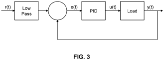
- FIG. 3 is a block diagram of an implementation of the downhole controller 253.
- the downhole controller 253 is a proportional-integral-derivative (PID) controller.
- the r(t) is the target process value (also referred as set point), and y(t) is the measured process value (also referred as operating point).
- the downhole controller 253 implements a feedback loop and calculates error value e(t) as the difference between the set point ( e(t) ) and the operating point ( y(t) ).
- the downhole controller 253 adjusts u(t) to minimize e(t) over time.
- the proportional component of the PID controller is proportional to the value of e(t).
- the integral component of the PID controller accounts for past values of e(t) and integrates them over time.
- the derivative component of the PID controller estimates a future value of e(t) based on a rate of change of e(t).
- the value for u(t) is calculated based on these three components and adjusted to minimize e(t), so that the operating point is maintained in proximity to the set point.
- r(t) passes through a lowpass filter.
- the downhole controller 253 adjusts u(t), such that the power output (for example, y(t) ) is maintained to be greater than a minimum power output threshold. For example, the downhole controller 253 calculates the difference between the target voltage output turbine-generator 251 and the actual measured value and adjusts the load to minimize this difference.
- the downhole controller 253 is configured to maintain steady power production while the low frequency sinusoidal signal causes low frequency fluctuations on the output generated by the turbine-generator 251.
- low frequency fluctuations can typically range from about 0.01 Hertz (Hz) to about 2 Hz.
- the downhole controller 253 is slower than the low frequency sinusoidal signal but fast enough to react to actual changes in operating conditions within a reasonable timeframe (for example, in a range of from about 1 minute to 3 minutes) to enable steady power supply to other onboard equipment that may be included in the downhole sub-system 250.
- the response time for the downhole controller 253 is longer than the duration of (that is, wavelength) of the low frequency sinusoidal signal, such that the downhole controller 253 does not interfere with and compensates for the load of the turbine-generator 251, resulting in a steady voltage output of the turbine-generator 251.
- the lowpass filtering with a long time constant and a hard limit can be implemented to ensure steady power production.
- the hard limit is an absolute minimum voltage that is set to be greater than the voltage of a battery of the downhole sub-system 250 in order to protect the battery and avoid draining/wasting energy while the turbine-generator 251 produces power.
- the hard limit can be 8 volts (V) for a 7.2 V battery pack, such as two 3.6 V lithium cells in series.
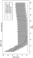
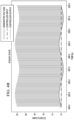
- FIGs. 4A and 4B are plots of various voltages against different time scales relating to the turbine-generator 251 and the downhole controller 253.
- FIG. 4A depicts data associated with a startup sequence
- FIG. 4B depicts data associated with operation at steady state a time period after startup when the process has stabilized.
- low frequency behavior is exhibited by the voltage output of the turbine-generator 251, and the operating point (controller output) is maintained to ensure steady power production.
- "Controller Input” can be considered e(t)
- Controller Output can be considered y(t)
- “Generator Voltage” can be considered u(t).
- the voltage output of the turbine-generator 251 exhibits the low frequency sinusoidal signal, while the downhole controller 253 is stable and does not affect the load of the turbine-generator 251.
- This effect shown in FIG. 4B is a result of the downhole controller 253 operating more slowly than the low frequency sinusoidal signal (described previously).
- FIG. 5 is a flow chart of an example method 500 for wireless communication from surface equipment to downhole equipment.
- the method 500 can be implemented, for example, by system 200.
- a first portion of a fluid (such as the first portion 299a of the fluid 299) is flowed from a container (such as the container 212) to a surface valve sub-assembly (such as the surface valve sub-assembly 220).
- the surface valve sub-assembly includes the first dump valve 221a, the second dump valve 221b, the surface controller 223, and the return line 213.
- the surface controller 223 is communicatively coupled to the first and second dump valves 221a, 221b.
- the return line 213 is in fluid communication with the first and second dump valves 221a, 221b.
- fluid flow through each of the first and second dump valves 221a, 221b is adjusted by the surface controller 223.
- the first and second dump valves 221a, 221b are in a parallel flow configuration.
- the method 500 includes adjusting, by the surface controller 223, a split of the first portion 299a between the first dump valve 221a and the second dump valve 221b.
- the second portion 299b of the fluid 299 is flowed from the container 212 to a downhole sub-system disposed within a wellbore (such as the downhole sub-system 250 disposed within the well 100).
- the downhole sub-system 250 includes the turbine-generator 251 and the downhole controller 253.
- the downhole controller 253 is coupled to the turbine-generator 251.
- flowing the second portion 299b to the downhole sub-system 250 at step 508 includes flowing the second portion 299b through a coiled tubing (such as the coiled tubing 290) that is fluidically coupled to the turbine-generator 251.
- the second portion 299b of the fluid 299 is received by the turbine-generator 251.
- an output (for example, a frequency output, a power output, a current output, or a voltage output) is generated by the turbine-generator 251 in response to receiving the second portion 299b of the fluid 299 at step 510.
- the output (and/or a change in the output) from the turbine-generator 251 (generated at step 512) is received by the downhole controller 253.
- receiving the second portion 299b by the turbine-generator 251 at step 510 includes receiving the sinusoidal signal via the second portion 299b and changing the output generated by the turbine-generator 251 at step 512 in response to receiving the sinusoidal signal.
- the downhole sub-system 250 includes a circulation valve (such as the circulation valve 252) downstream of the turbine-generator 251 and communicatively coupled to the downhole controller 253.
- the method 500 includes processing, by the downhole controller 253, the change in the output, for example, generated by the turbine-generator 251 at step 512 in response to receiving the sinusoidal signal.
- the method 500 includes adjusting, by the downhole controller 253, fluid flow through the circulation valve 252 at least based on the processing of the change in the output, for example, generated by the turbine-generator 251 at step 512 in response to receiving the sinusoidal signal.
- processing, by the downhole controller 253, the change in the output includes processing the change in the output, such that the power output of the turbine-generator 251 is maintained to be greater than a minimum power output threshold.
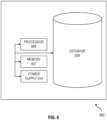
- FIG. 6 is a block diagram of an example controller 600 used to provide computational functionalities associated with described algorithms, methods, functions, processes, flows, and procedures, as described in this specification, according to an implementation.
- each of the surface controller 223 and the downhole controller 253 can be implementations of the controller 600.
- the illustrated controller 600 is intended to encompass any computing device such as a server, desktop computer, laptop/notebook computer, one or more processors within these devices, or any other processing device, including physical or virtual instances (or both) of the computing device.
- the controller 600 can include a computer that includes an input device, such as a keypad, keyboard, touch screen, or other device that can accept user information, and an output device that conveys information associated with the operation of the computer 600, including digital data, visual, audio information, or a combination of information.
- an input device such as a keypad, keyboard, touch screen, or other device that can accept user information
- an output device that conveys information associated with the operation of the computer 600, including digital data, visual, audio information, or a combination of information.
- the controller 600 includes a processor 605. Although illustrated as a single processor 605 in FIG. 6 , two or more processors may be used according to particular needs, desires, or particular implementations of the controller 600. Generally, the processor 605 executes instructions and manipulates data to perform the operations of the controller 600 and any algorithms, methods, functions, processes, flows, and procedures as described in this specification.
- the controller 600 can also include a database 606 that can hold data for the controller 600 or other components (or a combination of both) that can be connected to the network. Although illustrated as a single database 606 in FIG. 6 , two or more databases (of the same or combination of types) can be used according to particular needs, desires, or particular implementations of the controller 600 and the described functionality. While database 606 is illustrated as an integral component of the controller 600, database 606 can be external to the controller 600.
- the controller 600 includes a memory 607 that can hold data for the controller 600 or other components (or a combination of both) that can be connected to the network. Although illustrated as a single memory 607 in FIG. 6 , two or more memories 607 (of the same or combination of types) can be used according to particular needs, desires, or particular implementations of the controller 600 and the described functionality. While memory 607 is illustrated as an integral component of the controller 600, memory 607 can be external to the controller 600. The memory 607 can be a transitory or non-transitory storage medium.
- the memory 607 stores controller-readable instructions executable by the processor 605 that, when executed, cause the processor 605 to perform operations, such as adjust fluid flow through each of the first and second dump valves 221a, 221b.
- the controller 600 can also include a power supply 614.
- the power supply 614 can include a rechargeable or non-rechargeable battery that can be configured to be either user- or non-user-replaceable.
- the power supply 614 can be hard-wired.
- client “user,” “operator,” and other appropriate terminology may be used interchangeably, as appropriate, without departing from this specification.
- this specification contemplates that many users may use one controller 600, or that one user may use multiple controllers 600.
- the term "about” or “approximately” can allow for a degree of variability in a value or range, for example, within 10%, within 5%, or within 1% of a stated value or of a stated limit of a range.
- the term “substantially” refers to a majority of, or mostly, as in at least about 50%, 60%, 70%, 80%, 90%, 95%, 96%, 97%, 98%, 99%, 99.5%, 99.9%, 99.99%, or at least about 99.999% or more.
Landscapes
- Engineering & Computer Science (AREA)
- Life Sciences & Earth Sciences (AREA)
- Mining & Mineral Resources (AREA)
- Geology (AREA)
- Physics & Mathematics (AREA)
- Environmental & Geological Engineering (AREA)
- Fluid Mechanics (AREA)
- General Life Sciences & Earth Sciences (AREA)
- Geochemistry & Mineralogy (AREA)
- Geophysics (AREA)
- Remote Sensing (AREA)
- Acoustics & Sound (AREA)
- Control Of Eletrric Generators (AREA)
- Control Of Turbines (AREA)
- Other Liquid Machine Or Engine Such As Wave Power Use (AREA)
Claims (16)
- System (200), umfassend:i) ein Übertage-Untersystem (210), das Folgendes umfassteine Pumpe (211), die dazu ausgelegt ist, ein Fluid aus einem Behälter (212) unter Tage in ein Bohrloch zu pumpen; undeine Übertage-Ventilunterbaugruppe (220), die strömungstechnisch mit der Pumpe gekoppelt und dazu ausgelegt ist, einen ersten Teil (299a) eines durch die Pumpe gepumpten Fluids (299) zu empfangen, wobei die Übertage-Ventilunterbaugruppe Folgendes umfasst:ein Ablassventil (221),eine Übertage-Steuerung (223), die kommunikativ mit dem Ablassventil gekoppelt ist, wobei die Übertage-Steuerung dazu ausgelegt ist, eine Fluidströmung durch das Ablassventil anzupassen, undeine Rückleitung (213) in strömungstechnischer Verbindung mit dem Ablassventil, wobei die Rückleitung dazu ausgelegt ist, Fluid von dem Ablassventil zu dem Behälter zu leiten; undii) ein Untertage-Untersystem (250), das mit der Übertage-Ventilunterbaugruppe gekoppelt und dazu ausgelegt ist, innerhalb des Bohrlochs angeordnet zu sein, wobei das Untertage-Untersystem Folgendes umfasst einen Turbinengenerator (251), der dazu ausgelegt ist, als Reaktion auf ein Empfangen eines zweiten Teils des durch die Pumpe gepumpten Fluids eine Ausgabe zu erzeugen, undeine Untertage-Steuerung (253), die mit dem Turbinengenerator gekoppelt ist.
- System nach Anspruch 1, wobei das Ablassventil (221) ein erstes Ablassventil ist, die Übertage-Ventilunterbaugruppe ein zweites Ablassventil (221) umfasst und sich das erste Ablassventil und das zweite Ablassventil in einer parallelen Strömungsauslegung befinden.
- System nach Anspruch 2, wobei das Untertage-Untersystem und die Übertage-Ventilunterbaugruppe durch ein gewendeltes Rohr (290) gekoppelt sind, das die Pumpe strömungstechnisch mit dem Turbinengenerator koppelt.
- System nach Anspruch 3, wobei die Übertage-Steuerung Folgendes umfasst:einen Übertage-Prozessor (605); undein computerlesbares Übertage-Speichermedium (607), das mit dem Übertage-Prozessor gekoppelt ist und Programmierungsanweisungen zur Ausführung durch den Übertage-Prozessor speichert, wobei die Programmierungsanweisungen den Übertage-Prozessor anweisen, Operationen durchzuführen, die Anpassen einer Menge des ersten Teils des durch die Pumpe gepumpten Fluids durch Anpassen einer Fluidströmung durch jeweils das erste Ablassventil und das zweite Ablassventil, so dass ein sinusförmiges Signal über den zweiten Teil des von der Pumpe gepumpten Fluids hydraulisch an das Untertage-Untersystem übertragen wird, umfassen.
- System nach Anspruch 4, wobei der Turbinengenerator dazu ausgelegt ist, das sinusförmige Signal über den zweiten Teil des durch die Pumpe gepumpten Fluids zu empfangen und die Ausgabe als Reaktion auf das Empfangen des sinusförmigen Signals zu ändern, und wobei die Untertage-Steuerung dazu ausgelegt ist, die Änderung der Ausgabe zu verarbeiten.
- System nach Anspruch 5, wobei die Übertage-Steuerung dazu ausgelegt ist, das sinusförmige Signal, das hydraulisch über den zweiten Teil des durch die Pumpe gepumpten Fluids an das Untertage-Untersystem übertragen wird, zu modulieren, und die Untertage-Steuerung dazu ausgelegt ist, das sinusförmige Signal, das hydraulisch über den zweiten Teil des durch die Pumpe gepumpten Fluids an das Untertage-Untersystem übertragen wird, zu demodulieren, und
wobei optional die Untertage-Steuerung dazu ausgelegt ist, die Änderung der Ausgabe des Turbinengenerators derart zu verarbeiten, dass eine Leistungsausgabe des Turbinengenerators so aufrechterhalten wird, dass sie größer als ein Leistungsausgabe-Minimalschwellenwert ist. - System nach Anspruch 1, wobei:das Übertage-Untersystem mehrere Ablassventile (221) umfasst;die Übertage-Steuerung kommunikativ mit den mehreren Ablassventilen gekoppelt und dazu ausgelegt ist, eine Fluidströmung durch jedes der mehreren Ablassventile anzupassen; unddie Rückleitung in strömungstechnischer Verbindung mit den mehreren Ablassventilen steht und dazu ausgelegt ist, Fluid von den mehreren Ablassventilen zu dem Behälter zu leiten, der einen Zulauf zu der Pumpe bereitstellt;das Untertage-Untersystem ein Umlaufventil (252) stromabwärts des Turbinengenerators umfasst; unddie Untertage-Steuerung kommunikativ mit dem Umlaufventil gekoppelt ist, wobei die Untertage-Steuerung dazu ausgelegt ist, den Fluidstrom durch das Umlaufventil als Reaktion auf das Empfangen der Ausgabe von dem Turbinengenerator anzupassen.
- System nach Anspruch 7, wobei sich die mehreren Ablassventile in einer parallelen Strömungsauslegung befinden und wobei das Untertage-Untersystem und das Übertage-Untersystem durch ein gewendeltes Rohr (290) gekoppelt sind.
- System nach Anspruch 8, wobei:
die Übertage-Steuerung Folgendes umfasst:einen Übertage-Prozessor; undein computerlesbares Übertage-Speichermedium, das mit dem Übertage-Prozessor gekoppelt ist und Übertage-Programmierungsanweisungen zur Ausführung durch den Übertage-Prozessor speichert, wobei die Übertage-Programmierungsanweisungen den Übertage-Prozessor anweisen, Übertage-Operationen durchzuführen; unddie Untertage-Steuerung Folgendes umfasst:einen Untertage-Prozessor (605); undein computerlesbares Untertage-Speichermedium (607), das mit dem Untertage-Prozessor gekoppelt ist und Untertage-Programmierungsanweisungen zur Ausführung durch den Untertage-Prozessor speichert, wobei die Untertage-Programmierungsanweisungen den Untertage-Prozessor anweisen, Untertage-Operationen durchzuführen. - Verfahren, umfassend:
Leiten eines ersten Teils (299a) eines Fluids (299) von einem Behälter (212) zu einer Übertage-Ventilunterbaugruppe (220), wobei die Übertage-Ventilunterbaugruppe Folgendes umfasst:ein Ablassventil (221);eine Übertage-Steuerung (223), die kommunikativ mit dem Ablassventil gekoppelt ist; undeine Rückleitung (213) in strömungstechnischer Verbindung mit dem Ablassventil;Anpassen, durch die Übertage-Steuerung (223), einer Fluidströmung durch das Ablassventil;Leiten, durch die Rückleitung, des ersten Teils des Fluids zu dem Behälter;Leiten eines zweiten Teils des Fluids von dem Behälter zu einem Untertage-Untersystem, das in einem Bohrloch angeordnet ist, wobei das Untertage-Untersystem einen Turbinengenerator (251) und eine Untertage-Steuerung (253) umfasst, die mit dem Turbinengenerator gekoppelt ist;Empfangen, durch den Turbinengenerator, des zweiten Teils des Fluids;Erzeugen, durch den Turbinengenerator, einer Ausgabe als Reaktion auf das Empfangen des zweiten Teils des Fluids;Empfangen, durch die Untertage-Steuerung, der Ausgabe von dem Turbinengenerator; undÜbertragen, durch die Untertage-Steuerung, eines Steuersignals als Reaktion auf das Empfangen der Ausgabe von dem Turbinengenerator. - Verfahren nach Anspruch 10, wobei das Leiten des zweiten Teils des Fluids von dem Behälter zu dem Untertage-Untersystem Leiten des zweiten Teils des Fluids durch ein gewendeltes Rohr (290), das strömungstechnisch mit dem Turbinengenerator gekoppelt ist, umfasst.
- Verfahren nach Anspruch 11, wobei das Ablassventil ein erstes Ablassventil (221) ist, die Übertage-Ventilunterbaugruppe ein zweites Ablassventil (221) umfasst, sich das erste Ablassventil und das zweite Ablassventil in einer parallelen Strömungsauslegung befinden und das Verfahren Anpassen, durch die Übertage-Steuerung, einer Aufteilung des ersten Teils des Fluids zwischen dem ersten Ablassventil und dem zweiten Ablassventil umfasst.
- Verfahren nach Anspruch 12, wobei das Anpassen der Aufteilung des ersten Teils des Fluids zwischen dem ersten Ablassventil und dem zweiten Ablassventil Anpassen der Fluidströmung durch jeweils das erste Ablassventil und das zweite Ablassventil derart, dass ein sinusförmiges Signal hydraulisch über den zweiten Teil des Fluids an das Untertage-Untersystem übertragen wird, umfasst.
- Verfahren nach Anspruch 13, umfassend Empfangen, durch den Turbinengenerator, des sinusförmigen Signals über den zweiten Teil des Fluids und Ändern der durch den Turbinengenerator erzeugten Ausgabe als Reaktion auf das Empfangen des sinusförmigen Signals.
- Verfahren nach Anspruch 14, wobei:das Untertage-Untersystem ein Umlaufventil (252) stromabwärts des Turbinengenerators (251) umfasst, wobei das Umlaufventil kommunikativ mit der Untertage-Steuerung (253) gekoppelt ist; unddas Verfahren Folgendes umfasst:Verarbeiten, durch die Untertage-Steuerung, der Änderung der Ausgabe; undAnpassen, durch die Untertage-Steuerung, einer Fluidströmung durch das Umlaufventil mindestens basierend auf der Verarbeitung der Änderung der Ausgabe.
- Verfahren nach Anspruch 15, umfassend:Modulieren, durch die Übertage-Steuerung, des sinusförmigen Signals, das hydraulisch über den zweiten Teil des Fluids an das Untertage-Untersystem übertragen wird; undDemodulieren, durch die Untertage-Steuerung, des sinusförmigen Signals, das hydraulisch über den zweiten Teil des Fluids an das Untertage-Untersystem übertragen wird, undwobei optional das Verarbeiten der Änderung der Ausgabe Verarbeiten der Änderung der Ausgabe derart, dass die Leistungsausgabe des Turbinengenerators so aufrechterhalten wird, dass sie größer als ein Leistungsausgabe-Minimalschwellenwert ist, umfasst.
Applications Claiming Priority (2)
| Application Number | Priority Date | Filing Date | Title |
|---|---|---|---|
| US17/178,880 US11530597B2 (en) | 2021-02-18 | 2021-02-18 | Downhole wireless communication |
| PCT/US2022/016967 WO2022178247A1 (en) | 2021-02-18 | 2022-02-18 | Downhole wireless communication |
Publications (2)
| Publication Number | Publication Date |
|---|---|
| EP4295014A1 EP4295014A1 (de) | 2023-12-27 |
| EP4295014B1 true EP4295014B1 (de) | 2025-04-30 |
Family
ID=80683785
Family Applications (1)
| Application Number | Title | Priority Date | Filing Date |
|---|---|---|---|
| EP22709105.5A Active EP4295014B1 (de) | 2021-02-18 | 2022-02-18 | Drahtlose bohrloch kommunikation |
Country Status (3)
| Country | Link |
|---|---|
| US (1) | US11530597B2 (de) |
| EP (1) | EP4295014B1 (de) |
| WO (1) | WO2022178247A1 (de) |
Family Cites Families (164)
| Publication number | Priority date | Publication date | Assignee | Title |
|---|---|---|---|---|
| US2643723A (en) | 1947-12-11 | 1953-06-30 | Lynes Inc | Oil well tool |
| US3175618A (en) | 1961-11-06 | 1965-03-30 | Pan American Petroleum Corp | Apparatus for placing a liner in a vessel |
| US3448305A (en) | 1966-10-11 | 1969-06-03 | Aquitaine Petrole | Apparatus for producing and utilising electrical energy for use in drilling operations |
| US3558936A (en) | 1967-07-19 | 1971-01-26 | John J Horan | Resonant energy-conversion system |
| US3663845A (en) | 1971-02-18 | 1972-05-16 | Us Navy | Fluidic generator |
| GB1462359A (en) | 1973-08-31 | 1977-01-26 | Russell M K | Power generation in underground drilling operations |
| US3918520A (en) | 1974-09-30 | 1975-11-11 | Chevron Res | Wire line inflatable packer apparatus |
| US3916999A (en) | 1974-12-20 | 1975-11-04 | Dresser Ind | Retention sleeve for well tools and method of use thereof |
| US5113379A (en) | 1977-12-05 | 1992-05-12 | Scherbatskoy Serge Alexander | Method and apparatus for communicating between spaced locations in a borehole |
| US4387318A (en) | 1981-06-04 | 1983-06-07 | Piezo Electric Products, Inc. | Piezoelectric fluid-electric generator |
| US4536674A (en) | 1984-06-22 | 1985-08-20 | Schmidt V Hugo | Piezoelectric wind generator |
| US4685523A (en) | 1986-05-06 | 1987-08-11 | Otis Engineering Corporation | Removable side pocket mandrel |
| US5317223A (en) | 1987-01-21 | 1994-05-31 | Dynamotive Corporation | Method and device in magnetostrictive motion systems |
| FR2631653B1 (fr) | 1988-05-19 | 1990-08-17 | Schlumberger Prospection | Procede pour introduire un outil dans un puits sous pression |
| US4940095A (en) | 1989-01-27 | 1990-07-10 | Dowell Schlumberger Incorporated | Deployment/retrieval method and apparatus for well tools used with coiled tubing |
| GB8915994D0 (en) | 1989-07-12 | 1989-08-31 | Schlumberger Ind Ltd | Vortex flowmeters |
| US5092176A (en) | 1990-06-29 | 1992-03-03 | The Babcock & Wilcox Company | Method for determining deposit buildup |
| US5224182A (en) | 1991-08-29 | 1993-06-29 | Virginia Polytechnic Institute And State University | Spatially-weighted two-mode optical fiber sensors |
| US5215151A (en) | 1991-09-26 | 1993-06-01 | Cudd Pressure Control, Inc. | Method and apparatus for drilling bore holes under pressure |
| NO306522B1 (no) | 1992-01-21 | 1999-11-15 | Anadrill Int Sa | Fremgangsmaate for akustisk overföring av maalesignaler ved maaling under boring |
| US5301760C1 (en) | 1992-09-10 | 2002-06-11 | Natural Reserve Group Inc | Completing horizontal drain holes from a vertical well |
| US5375622A (en) | 1993-12-07 | 1994-12-27 | Houston; Reagan | Multiport valve including leakage control system, particularly for a thermal regenerative fume incinerator |
| US5566762A (en) | 1994-04-06 | 1996-10-22 | Tiw Corporation | Thru tubing tool and method |
| US5613555A (en) | 1994-12-22 | 1997-03-25 | Dowell, A Division Of Schlumberger Technology Corporation | Inflatable packer with wide slat reinforcement |
| FR2737533B1 (fr) | 1995-08-04 | 1997-10-24 | Drillflex | Manchon tubulaire gonflable pour tuber ou obturer un puits ou une canalisation |
| US6068015A (en) | 1996-08-15 | 2000-05-30 | Camco International Inc. | Sidepocket mandrel with orienting feature |
| US5892860A (en) | 1997-01-21 | 1999-04-06 | Cidra Corporation | Multi-parameter fiber optic sensor for use in harsh environments |
| CA2279646C (en) | 1997-02-03 | 2006-01-17 | Bj Services Company, U.S.A. | Deployment system and apparatus for running bottomhole assemblies in wells, particularly applicable to coiled tubing operations |
| US5708500A (en) | 1997-02-04 | 1998-01-13 | Tektronix, Inc. | Multimode optical time domain reflectometer having improved resolution |
| CA2264632C (en) | 1997-05-02 | 2007-11-27 | Baker Hughes Incorporated | Wellbores utilizing fiber optic-based sensors and operating devices |
| US20020043404A1 (en) | 1997-06-06 | 2002-04-18 | Robert Trueman | Erectable arm assembly for use in boreholes |
| US5965964A (en) | 1997-09-16 | 1999-10-12 | Halliburton Energy Services, Inc. | Method and apparatus for a downhole current generator |
| US5975205A (en) | 1997-09-30 | 1999-11-02 | Carisella; James V. | Gravel pack apparatus and method |
| US6082455A (en) | 1998-07-08 | 2000-07-04 | Camco International Inc. | Combination side pocket mandrel flow measurement and control assembly |
| US6193079B1 (en) | 1999-04-29 | 2001-02-27 | Dci Marketing, Inc. | Product display and support |
| US6349768B1 (en) | 1999-09-30 | 2002-02-26 | Schlumberger Technology Corporation | Method and apparatus for all multilateral well entry |
| US6728165B1 (en) | 1999-10-29 | 2004-04-27 | Litton Systems, Inc. | Acoustic sensing system for downhole seismic applications utilizing an array of fiber optic sensors |
| WO2002010553A1 (en) | 2000-01-28 | 2002-02-07 | Halliburton Energy Services, Inc. | Vibration based power generator |
| GB2383633A (en) | 2000-06-29 | 2003-07-02 | Paulo S Tubel | Method and system for monitoring smart structures utilizing distributed optical sensors |
| US6920085B2 (en) | 2001-02-14 | 2005-07-19 | Halliburton Energy Services, Inc. | Downlink telemetry system |
| US6578638B2 (en) | 2001-08-27 | 2003-06-17 | Weatherford/Lamb, Inc. | Drillable inflatable packer & methods of use |
| US6779601B2 (en) | 2002-01-16 | 2004-08-24 | Weatherford/Lamb, Inc. | Inflatable packing element |
| AU2002952790A0 (en) | 2002-11-18 | 2002-12-05 | Microtechnology Centre Management Limited | Motion activated power source |
| US7397388B2 (en) | 2003-03-26 | 2008-07-08 | Schlumberger Technology Corporation | Borehold telemetry system |
| US8681000B2 (en) | 2003-04-09 | 2014-03-25 | Visible Assets, Inc. | Low frequency inductive tagging for lifecycle management |
| US20070012437A1 (en) | 2003-07-14 | 2007-01-18 | Clingman Scott R | Inflatable packer |
| US7320370B2 (en) * | 2003-09-17 | 2008-01-22 | Schlumberger Technology Corporation | Automatic downlink system |
| US7224077B2 (en) | 2004-01-14 | 2007-05-29 | Ocean Power Technologies, Inc. | Bluff body energy converter |
| US7199480B2 (en) | 2004-04-15 | 2007-04-03 | Halliburton Energy Services, Inc. | Vibration based power generator |
| US20060042792A1 (en) | 2004-08-24 | 2006-03-02 | Connell Michael L | Methods and apparatus for locating a lateral wellbore |
| US20060086498A1 (en) | 2004-10-21 | 2006-04-27 | Schlumberger Technology Corporation | Harvesting Vibration for Downhole Power Generation |
| US20090114001A1 (en) | 2007-05-25 | 2009-05-07 | Bernitsas Michael M | Enhancement of vortex induced forces and motion through surface roughness control |
| EP1856789B1 (de) | 2005-02-08 | 2018-08-15 | Welldynamics, Inc. | Elektrischer bohrloch-stromgenerator |
| NO20053684A (no) | 2005-08-01 | 2006-12-18 | Well Innovation As | Justerbart sentreringsverktøy til bruk i rør med ulik indre diameter |
| US20080100828A1 (en) | 2005-09-29 | 2008-05-01 | Normand Cyr | Polarization-sensitive optical time domain reflectometer and method for determining PMD |
| US7410003B2 (en) | 2005-11-18 | 2008-08-12 | Bj Services Company | Dual purpose blow out preventer |
| GB0525989D0 (en) | 2005-12-21 | 2006-02-01 | Qinetiq Ltd | Generation of electrical power from fluid flows |
| US7635027B2 (en) | 2006-02-08 | 2009-12-22 | Tolson Jet Perforators, Inc. | Method and apparatus for completing a horizontal well |
| US7345372B2 (en) | 2006-03-08 | 2008-03-18 | Perpetuum Ltd. | Electromechanical generator for, and method of, converting mechanical vibrational energy into electrical energy |
| US20080048455A1 (en) | 2006-08-25 | 2008-02-28 | Matthew Eli Carney | Energy capture in flowing fluids |
| US7847421B2 (en) | 2007-01-19 | 2010-12-07 | Willowview Systems, Inc. | System for generating electrical energy from ambient motion |
| US20130167628A1 (en) | 2007-02-15 | 2013-07-04 | Hifi Engineering Inc. | Method and apparatus for detecting an acoustic event along a channel |
| DE102007049418B4 (de) | 2007-10-12 | 2016-12-08 | Airbus Defence and Space GmbH | Piezoelektrischer Mikrogenerator |
| EP2218120A2 (de) | 2007-10-29 | 2010-08-18 | Humdinger Wind Energy LLC | Energieumsetzer mit wandlern zum umsetzen von durch fluid verursachten bewegungen oder anspannungen in elektrizität |
| US20090107725A1 (en) | 2007-10-30 | 2009-04-30 | Christy Thomas M | System and method for logging soil properties in a borehole |
| US7946341B2 (en) | 2007-11-02 | 2011-05-24 | Schlumberger Technology Corporation | Systems and methods for distributed interferometric acoustic monitoring |
| US7906861B2 (en) | 2007-11-28 | 2011-03-15 | Schlumberger Technology Corporation | Harvesting energy in remote locations |
| CN101488805B (zh) | 2008-01-15 | 2012-08-29 | 电子科技大学 | 光纤扰动探测方法及装置 |
| NO333810B1 (no) | 2008-04-02 | 2013-09-23 | Well Technology As | Anordning og fremgangsmåte for energigenerering nede i et borehull |
| US7980309B2 (en) | 2008-04-30 | 2011-07-19 | Halliburton Energy Services, Inc. | Method for selective activation of downhole devices in a tool string |
| US7668411B2 (en) | 2008-06-06 | 2010-02-23 | Schlumberger Technology Corporation | Distributed vibration sensing system using multimode fiber |
| GB2465717B (en) | 2008-07-16 | 2011-10-05 | Halliburton Energy Serv Inc | Apparatus and method for generating power downhole |
| EP2304422B1 (de) | 2008-07-22 | 2020-01-08 | Nederlandse Organisatie voor toegepast- natuurwetenschappelijk onderzoek TNO | Korrosionskontrolle |
| US8408064B2 (en) | 2008-11-06 | 2013-04-02 | Schlumberger Technology Corporation | Distributed acoustic wave detection |
| JP4581013B2 (ja) | 2008-12-30 | 2010-11-17 | 強化土エンジニヤリング株式会社 | 注入管装置、および地盤注入工法 |
| US8102072B2 (en) | 2008-12-31 | 2012-01-24 | Kuei-Sheng Tsou | Aerodynamic vibration power-generation device |
| EP2380180B1 (de) | 2009-01-02 | 2019-11-27 | JDI International Leasing Limited | Zuverlässiges system zur übertragung von daten eines verdrahteten rohres |
| US9239043B1 (en) | 2009-02-17 | 2016-01-19 | Jaime (“James”) Teodoro Zeas | Conversion of kinetic into electric energy utilizing the universal principles of gravity and magnetism |
| US8604634B2 (en) | 2009-06-05 | 2013-12-10 | Schlumberger Technology Corporation | Energy harvesting from flow-induced vibrations |
| CN101592475B (zh) | 2009-06-08 | 2010-09-29 | 中国计量学院 | 全分布式光纤瑞利与拉曼散射光子应变、温度传感器 |
| RU2543719C2 (ru) | 2009-07-15 | 2015-03-10 | Шелл Интернэшнл Рисерч Маатсхаппий Б.В. | Способ конверсии углеводородного сырья |
| CN201496028U (zh) | 2009-07-24 | 2010-06-02 | 中国石油集团川庆钻探工程有限公司工程技术研究院 | 内管串工具胀封套管外封隔器 |
| WO2011015120A1 (zh) | 2009-08-04 | 2011-02-10 | 天津空中代码工程应用软件开发有限公司 | 卡门涡街发电装置 |
| US8916983B2 (en) | 2009-09-10 | 2014-12-23 | Schlumberger Technology Corporation | Electromagnetic harvesting of fluid oscillations for downhole power sources |
| US8258644B2 (en) | 2009-10-12 | 2012-09-04 | Kaplan A Morris | Apparatus for harvesting energy from flow-induced oscillations and method for the same |
| US20110088462A1 (en) | 2009-10-21 | 2011-04-21 | Halliburton Energy Services, Inc. | Downhole monitoring with distributed acoustic/vibration, strain and/or density sensing |
| WO2011050294A2 (en) | 2009-10-22 | 2011-04-28 | Cornell University | Device and system for harvesting energy |
| US8421251B2 (en) | 2010-03-26 | 2013-04-16 | Schlumberger Technology Corporation | Enhancing the effectiveness of energy harvesting from flowing fluid |
| US8763696B2 (en) | 2010-04-27 | 2014-07-01 | Sylvain Bedouet | Formation testing |
| US8792304B2 (en) * | 2010-05-24 | 2014-07-29 | Schlumberger Technology Corporation | Downlinking communication system and method using signal transition detection |
| US9140815B2 (en) | 2010-06-25 | 2015-09-22 | Shell Oil Company | Signal stacking in fiber optic distributed acoustic sensing |
| US8997854B2 (en) | 2010-07-23 | 2015-04-07 | Weatherford Technology Holdings, Llc | Swellable packer anchors |
| US8564179B2 (en) | 2010-08-03 | 2013-10-22 | Baker Hughes Incorporated | Apparatus and method for downhole energy conversion |
| WO2012030814A2 (en) | 2010-09-01 | 2012-03-08 | Schlumberger Canada Limited | Distributed fiber optic sensor system with improved linearity |
| WO2012066550A1 (en) | 2010-11-16 | 2012-05-24 | Technion Research And Development Foundation Ltd. | Energy conversion from fluid flow |
| US20130119669A1 (en) | 2010-12-21 | 2013-05-16 | Oscilla Power Inc. | Method and device for harvesting energy from fluid flow |
| EP2656406A4 (de) | 2010-12-21 | 2014-09-17 | Oscilla Power Inc | Vorrichtung zur gewinnung von vibrationsenergie |
| NO345967B1 (no) | 2011-02-21 | 2021-11-22 | Baker Hughes Holdings Llc | Brønnklemmeanordning |
| GB201104694D0 (en) | 2011-03-21 | 2011-05-04 | Read Well Services Ltd | Apparatus and method |
| US9222465B2 (en) | 2011-04-15 | 2015-12-29 | Northeastern University | Non-rotating wind energy generator |
| US8493555B2 (en) | 2011-04-29 | 2013-07-23 | Corning Incorporated | Distributed Brillouin sensing systems and methods using few-mode sensing optical fiber |
| EP2540957A1 (de) | 2011-06-30 | 2013-01-02 | Welltec A/S | Bohrlochwerkzeug zur Bestimmung von Seitenkanälen |
| US9347332B2 (en) | 2011-07-28 | 2016-05-24 | Mitsui Engineering & Shipbuilding | Dynamo with columnar oscillator |
| US9322389B2 (en) | 2011-09-01 | 2016-04-26 | Chevron U.S.A. Inc. | Power generation in a tubular structure by way of electromagnetic induction |
| US9470059B2 (en) | 2011-09-20 | 2016-10-18 | Saudi Arabian Oil Company | Bottom hole assembly for deploying an expandable liner in a wellbore |
| CA2852676C (en) | 2011-10-18 | 2018-03-13 | Cidra Corporate Services Inc. | Acoustic probing technique for the determination of interior pipe coating wear or scale build-up and liner wear |
| US9109573B2 (en) | 2012-02-03 | 2015-08-18 | Incurrent Turbines Ltd. | Bluff body turbine and method |
| US8948550B2 (en) | 2012-02-21 | 2015-02-03 | Corning Incorporated | Sensing systems and few-mode optical fiber for use in such systems |
| CA2770979A1 (en) | 2012-03-08 | 2013-09-08 | Cathedral Energy Services Ltd. | Method for transmission of data from a downhole sensor array |
| US9091144B2 (en) | 2012-03-23 | 2015-07-28 | Baker Hughes Incorporated | Environmentally powered transmitter for location identification of wellbores |
| US9638671B2 (en) | 2012-05-25 | 2017-05-02 | Fbs, Inc. | Systems and methods for damage detection in structures using guided wave phased arrays |
| US8648480B1 (en) | 2012-06-25 | 2014-02-11 | The United States Of America As Represented By The Secretary Of The Navy | Energy harvesting system using flow-induced vibrations |
| US9828853B2 (en) * | 2012-09-12 | 2017-11-28 | Halliburton Energy Services, Inc. | Apparatus and method for drilling fluid telemetry |
| DE202012103729U1 (de) | 2012-09-28 | 2012-10-22 | Ming Lu | Karman-Wirbelstraße-elektrischer Generator für Automobile |
| US9599505B2 (en) | 2012-12-10 | 2017-03-21 | The Government Of The United States Of America, As Represented By The Secretary Of The Navy | Fiber optic directional acoustic sensor |
| US9499460B2 (en) | 2012-12-19 | 2016-11-22 | Toray Industries, Inc. | Alcohol production method |
| US9581489B2 (en) | 2013-01-26 | 2017-02-28 | Halliburton Energy Services, Inc. | Distributed acoustic sensing with multimode fiber |
| EP3561222B1 (de) | 2013-02-25 | 2022-07-20 | Evolution Engineering Inc. | Integriertes bohrlochsystem mit mehreren telemetrieuntersystemen |
| US20140284937A1 (en) | 2013-03-20 | 2014-09-25 | Oscilla Power Inc. | Vibration energy harvester |
| US10115942B2 (en) | 2013-06-05 | 2018-10-30 | The Regents Of The University Of California | Rate-sensitive and self-releasing battery cells and battery-cell structures as structural and/or energy-absorbing vehicle components |
| US9321222B2 (en) | 2013-08-13 | 2016-04-26 | Baker Hughes Incorporated | Optical fiber sensing with enhanced backscattering |
| US20150053009A1 (en) | 2013-08-23 | 2015-02-26 | Fbs, Inc. | Ultrasonic guided wave corrosion detection and monitoring system and method for storage tank floors and other large-scale, complex, plate-like structures |
| WO2015030930A2 (en) | 2013-08-27 | 2015-03-05 | Exxonmobil Upstream Research Company | Systems and mehtods for artificial lift via a downhole piezoelectric pump |
| GB201315957D0 (en) | 2013-09-06 | 2013-10-23 | Swellfix Bv | Retrievable packer |
| US9574420B2 (en) | 2013-10-21 | 2017-02-21 | Onesubsea Ip Uk Limited | Well intervention tool and method |
| US9617847B2 (en) | 2013-10-29 | 2017-04-11 | Halliburton Energy Services, Inc. | Robust optical fiber-based distributed sensing systems and methods |
| US9429466B2 (en) | 2013-10-31 | 2016-08-30 | Halliburton Energy Services, Inc. | Distributed acoustic sensing systems and methods employing under-filled multi-mode optical fiber |
| WO2015073018A1 (en) | 2013-11-15 | 2015-05-21 | Halliburton Energy Services, Inc. | Assembling a perforating gun string within a casing string |
| WO2015076757A1 (en) | 2013-11-22 | 2015-05-28 | Agency For Science, Technology And Research | Device for determining a property of a fluid and method of forming the same |
| EP2908124A1 (de) | 2014-02-18 | 2015-08-19 | Nederlandse Organisatie voor toegepast- natuurwetenschappelijk onderzoek TNO | Verfahren und System zur Ultraschallprüfung von Bohrlöchern |
| EP3130013B1 (de) | 2014-04-11 | 2018-03-14 | Fondazione Istituto Italiano di Tecnologia | Vorrichtung zur energiegewinnung aus einer fluidströmung mit einer dünnen schicht aus piezoelektrischem material |
| CN103913186A (zh) | 2014-04-25 | 2014-07-09 | 重庆大学 | 基于瑞利散射和拉曼散射的多参数分布式光纤传感系统 |
| US9634766B2 (en) | 2014-04-30 | 2017-04-25 | Baker Hughes Incorporated | Distributed acoustic sensing using low pulse repetition rates |
| US20160168957A1 (en) | 2014-06-11 | 2016-06-16 | Tubel, LLC. | Magnetic Field Disruption For In-Well Power Conversion |
| US10444391B2 (en) | 2014-09-12 | 2019-10-15 | Halliburton Energy Services, Inc. | Noise removal for distributed acoustic sensing data |
| US8925649B1 (en) | 2014-09-23 | 2015-01-06 | Focus Tools Colorado, LLC | System to harvest energy in a wellbore |
| US9106159B1 (en) | 2014-09-23 | 2015-08-11 | Focus Tools Colorado, LLC | System to harvest energy in a wellbore |
| US9599460B2 (en) | 2014-10-16 | 2017-03-21 | Nec Corporation | Hybrid Raman and Brillouin scattering in few-mode fibers |
| US10113935B2 (en) | 2015-01-08 | 2018-10-30 | Nec Corporation | Distributed multi-channel coherent optical fiber sensing system |
| US10605036B2 (en) | 2015-02-13 | 2020-03-31 | Schlumberger Technology Corporation | Deployment blow out preventer with interlock |
| GB201503861D0 (en) | 2015-03-06 | 2015-04-22 | Silixa Ltd | Method and apparatus for optical sensing |
| US9803976B2 (en) | 2015-04-22 | 2017-10-31 | Clamp On As | Methods and apparatus for measurement or monitoring of wall thicknesses in the walls of pipes or similar structures |
| US9896912B2 (en) * | 2015-05-13 | 2018-02-20 | Baker Hughes, A Ge Company, Llc | Active rectifier for downhole applications |
| CN105043586B (zh) | 2015-05-28 | 2018-01-09 | 华中科技大学 | 一种基于少模光纤的拉曼分布式测温系统和测温方法 |
| US10393921B2 (en) | 2015-09-16 | 2019-08-27 | Schlumberger Technology Corporation | Method and system for calibrating a distributed vibration sensing system |
| US10724312B2 (en) | 2015-09-22 | 2020-07-28 | Schlumberger Technology Corporation | Coiled tubing bottom hole assembly deployment |
| CN105371943B (zh) | 2015-12-29 | 2018-06-26 | 成都瑞莱杰森科技有限公司 | 一种分布式光纤振动传感系统的解调方法及装置 |
| GB201601060D0 (en) | 2016-01-20 | 2016-03-02 | Fotech Solutions Ltd | Distributed optical fibre sensors |
| NO341973B1 (en) | 2016-02-24 | 2018-03-05 | Isealate As | Improvements relating to lining an internal wall of a conduit |
| US10465501B2 (en) | 2016-03-09 | 2019-11-05 | Conocophillips Company | DAS method of estimating fluid distribution |
| GB201609289D0 (en) | 2016-05-26 | 2016-07-13 | Metrol Tech Ltd | Method of pressure testing |
| EP3464818B1 (de) | 2016-06-07 | 2024-02-14 | Halliburton Energy Services, Inc. | Formationstesterwerkzeug |
| US10018558B2 (en) | 2016-08-22 | 2018-07-10 | Nec Corporation | Distributed acoustic sensing in a multicore optical fiber using distributed mode coupling, delay, and simultaneous pulsing with selectable spatial modes |
| US10584556B2 (en) | 2016-12-06 | 2020-03-10 | Saudi Arabian Oil Company | Thru-tubing subsurface completion unit employing detachable anchoring seals |
| US10563483B2 (en) | 2016-12-28 | 2020-02-18 | Halliburton Energy Services, Inc. | Actuatable deflector for a completion sleeve in multilateral wells |
| WO2018145215A1 (en) | 2017-02-13 | 2018-08-16 | Ncs Multistage Inc. | System and method for wireless control of well bore equipment |
| CN206496768U (zh) | 2017-02-23 | 2017-09-15 | 鞍山睿科光电技术有限公司 | 一种基于线性调频脉冲的相位敏感光时域反射计 |
| CN107144339A (zh) | 2017-05-17 | 2017-09-08 | 长沙理工大学 | 一种基于调制脉冲技术的分布式光纤传感系统 |
| US10367434B2 (en) | 2017-05-30 | 2019-07-30 | Saudi Arabian Oil Company | Harvesting energy from fluid flow |
| WO2019156668A1 (en) * | 2018-02-08 | 2019-08-15 | Halliburton Energy Services, Inc. | Electronic controlled fluidic siren based telemetry |
| CN108534910A (zh) | 2018-03-19 | 2018-09-14 | 浙江师范大学 | 一种基于非对称双芯光纤的分布式双参量传感方法 |
| US10934814B2 (en) | 2018-06-06 | 2021-03-02 | Saudi Arabian Oil Company | Liner installation with inflatable packer |
| US11112777B2 (en) | 2019-03-29 | 2021-09-07 | China Petroleum & Chemical Corporation | Independent high-speed sampling for an oil drilling system |
| NO20211509A1 (en) * | 2019-05-22 | 2021-12-15 | Baker Hughes Oilfield Operations Llc | Dual turbine power and wellbore communications apparatus |
-
2021
- 2021-02-18 US US17/178,880 patent/US11530597B2/en active Active
-
2022
- 2022-02-18 EP EP22709105.5A patent/EP4295014B1/de active Active
- 2022-02-18 WO PCT/US2022/016967 patent/WO2022178247A1/en not_active Ceased
Also Published As
| Publication number | Publication date |
|---|---|
| EP4295014A1 (de) | 2023-12-27 |
| US11530597B2 (en) | 2022-12-20 |
| US20220259950A1 (en) | 2022-08-18 |
| WO2022178247A1 (en) | 2022-08-25 |
Similar Documents
| Publication | Publication Date | Title |
|---|---|---|
| CA3137864C (en) | System and method for treatment optimization | |
| RU2267610C2 (ru) | Способ формирования гидравлического разрыва пласта | |
| US9057256B2 (en) | Submersible pump control | |
| EP1812683B2 (de) | System und verfahren zur drahtlosen kommunikation in einem förderbohrungssystem | |
| AU2013223875B2 (en) | Wireless communication | |
| EP2844831B1 (de) | Systeme und verfahren zur optimierung einer auf eine anlage begrenzten produktion und injektion in einem integrierten reservoir und einem sammlungsnetzwerk | |
| CN107018672A (zh) | 能源行业作业特征化和/或优化 | |
| US20160115776A1 (en) | Method and system to drill out well completion plugs | |
| US20240287883A1 (en) | Methods for improving performance of automated coiled tubing operations | |
| US11428049B2 (en) | Wellbore underreaming | |
| US20210123431A1 (en) | Synthetic data generation systems and methods | |
| US20230235644A1 (en) | Well testing operations using automated choke control | |
| US12247470B1 (en) | Enhancing connectivity between injector and producer wells using sequenced stimulation | |
| EP3414427B1 (de) | Abflussseitiges bohrlochkommunikationsverfahren und zugehörige systeme | |
| CN109057757A (zh) | 一种天然气水合物开采方法及装置 | |
| WO2021046115A1 (en) | Freeing stuck tubulars in wellbores | |
| US12467345B2 (en) | Wireless gas lift | |
| CN104854306A (zh) | 扩大的泥浆脉冲遥测 | |
| EP4295014B1 (de) | Drahtlose bohrloch kommunikation | |
| AU2018343100B2 (en) | A well with two casings | |
| CN116888343A (zh) | 钻井参数限制的动态调整 | |
| EP4301963B1 (de) | Drahtlose kommunikation im bohrloch | |
| WO2024033661A1 (en) | Wireless gas lift | |
| Healy et al. | Testing Green Canyon Wells with a Pressure-Pulse-Controlled DST System |
Legal Events
| Date | Code | Title | Description |
|---|---|---|---|
| STAA | Information on the status of an ep patent application or granted ep patent |
Free format text: STATUS: UNKNOWN |
|
| STAA | Information on the status of an ep patent application or granted ep patent |
Free format text: STATUS: THE INTERNATIONAL PUBLICATION HAS BEEN MADE |
|
| PUAI | Public reference made under article 153(3) epc to a published international application that has entered the european phase |
Free format text: ORIGINAL CODE: 0009012 |
|
| STAA | Information on the status of an ep patent application or granted ep patent |
Free format text: STATUS: REQUEST FOR EXAMINATION WAS MADE |
|
| 17P | Request for examination filed |
Effective date: 20230823 |
|
| AK | Designated contracting states |
Kind code of ref document: A1 Designated state(s): AL AT BE BG CH CY CZ DE DK EE ES FI FR GB GR HR HU IE IS IT LI LT LU LV MC MK MT NL NO PL PT RO RS SE SI SK SM TR |
|
| DAV | Request for validation of the european patent (deleted) | ||
| DAX | Request for extension of the european patent (deleted) | ||
| P01 | Opt-out of the competence of the unified patent court (upc) registered |
Free format text: CASE NUMBER: APP_40314/2024 Effective date: 20240707 |
|
| GRAP | Despatch of communication of intention to grant a patent |
Free format text: ORIGINAL CODE: EPIDOSNIGR1 |
|
| STAA | Information on the status of an ep patent application or granted ep patent |
Free format text: STATUS: GRANT OF PATENT IS INTENDED |
|
| INTG | Intention to grant announced |
Effective date: 20241218 |
|
| GRAJ | Information related to disapproval of communication of intention to grant by the applicant or resumption of examination proceedings by the epo deleted |
Free format text: ORIGINAL CODE: EPIDOSDIGR1 |
|
| STAA | Information on the status of an ep patent application or granted ep patent |
Free format text: STATUS: REQUEST FOR EXAMINATION WAS MADE |
|
| GRAP | Despatch of communication of intention to grant a patent |
Free format text: ORIGINAL CODE: EPIDOSNIGR1 |
|
| STAA | Information on the status of an ep patent application or granted ep patent |
Free format text: STATUS: GRANT OF PATENT IS INTENDED |
|
| GRAS | Grant fee paid |
Free format text: ORIGINAL CODE: EPIDOSNIGR3 |
|
| INTC | Intention to grant announced (deleted) | ||
| GRAA | (expected) grant |
Free format text: ORIGINAL CODE: 0009210 |
|
| STAA | Information on the status of an ep patent application or granted ep patent |
Free format text: STATUS: THE PATENT HAS BEEN GRANTED |
|
| INTG | Intention to grant announced |
Effective date: 20250226 |
|
| AK | Designated contracting states |
Kind code of ref document: B1 Designated state(s): AL AT BE BG CH CY CZ DE DK EE ES FI FR GB GR HR HU IE IS IT LI LT LU LV MC MK MT NL NO PL PT RO RS SE SI SK SM TR |
|
| REG | Reference to a national code |
Ref country code: CH Ref legal event code: EP Ref country code: GB Ref legal event code: FG4D |
|
| REG | Reference to a national code |
Ref country code: DE Ref legal event code: R096 Ref document number: 602022013889 Country of ref document: DE |
|
| REG | Reference to a national code |
Ref country code: IE Ref legal event code: FG4D |
|
| REG | Reference to a national code |
Ref country code: NL Ref legal event code: MP Effective date: 20250430 |
|
| REG | Reference to a national code |
Ref country code: AT Ref legal event code: MK05 Ref document number: 1790177 Country of ref document: AT Kind code of ref document: T Effective date: 20250430 |
|
| PG25 | Lapsed in a contracting state [announced via postgrant information from national office to epo] |
Ref country code: ES Free format text: LAPSE BECAUSE OF FAILURE TO SUBMIT A TRANSLATION OF THE DESCRIPTION OR TO PAY THE FEE WITHIN THE PRESCRIBED TIME-LIMIT Effective date: 20250430 Ref country code: FI Free format text: LAPSE BECAUSE OF FAILURE TO SUBMIT A TRANSLATION OF THE DESCRIPTION OR TO PAY THE FEE WITHIN THE PRESCRIBED TIME-LIMIT Effective date: 20250430 Ref country code: PT Free format text: LAPSE BECAUSE OF FAILURE TO SUBMIT A TRANSLATION OF THE DESCRIPTION OR TO PAY THE FEE WITHIN THE PRESCRIBED TIME-LIMIT Effective date: 20250901 |
|
| REG | Reference to a national code |
Ref country code: LT Ref legal event code: MG9D |
|
| PG25 | Lapsed in a contracting state [announced via postgrant information from national office to epo] |
Ref country code: GR Free format text: LAPSE BECAUSE OF FAILURE TO SUBMIT A TRANSLATION OF THE DESCRIPTION OR TO PAY THE FEE WITHIN THE PRESCRIBED TIME-LIMIT Effective date: 20250731 |
|
| PG25 | Lapsed in a contracting state [announced via postgrant information from national office to epo] |
Ref country code: NL Free format text: LAPSE BECAUSE OF FAILURE TO SUBMIT A TRANSLATION OF THE DESCRIPTION OR TO PAY THE FEE WITHIN THE PRESCRIBED TIME-LIMIT Effective date: 20250430 Ref country code: PL Free format text: LAPSE BECAUSE OF FAILURE TO SUBMIT A TRANSLATION OF THE DESCRIPTION OR TO PAY THE FEE WITHIN THE PRESCRIBED TIME-LIMIT Effective date: 20250430 |
|
| PG25 | Lapsed in a contracting state [announced via postgrant information from national office to epo] |
Ref country code: BG Free format text: LAPSE BECAUSE OF FAILURE TO SUBMIT A TRANSLATION OF THE DESCRIPTION OR TO PAY THE FEE WITHIN THE PRESCRIBED TIME-LIMIT Effective date: 20250430 |
|
| PG25 | Lapsed in a contracting state [announced via postgrant information from national office to epo] |
Ref country code: HR Free format text: LAPSE BECAUSE OF FAILURE TO SUBMIT A TRANSLATION OF THE DESCRIPTION OR TO PAY THE FEE WITHIN THE PRESCRIBED TIME-LIMIT Effective date: 20250430 |
|
| PG25 | Lapsed in a contracting state [announced via postgrant information from national office to epo] |
Ref country code: AT Free format text: LAPSE BECAUSE OF FAILURE TO SUBMIT A TRANSLATION OF THE DESCRIPTION OR TO PAY THE FEE WITHIN THE PRESCRIBED TIME-LIMIT Effective date: 20250430 |
|
| PG25 | Lapsed in a contracting state [announced via postgrant information from national office to epo] |
Ref country code: RS Free format text: LAPSE BECAUSE OF FAILURE TO SUBMIT A TRANSLATION OF THE DESCRIPTION OR TO PAY THE FEE WITHIN THE PRESCRIBED TIME-LIMIT Effective date: 20250731 |
|
| PG25 | Lapsed in a contracting state [announced via postgrant information from national office to epo] |
Ref country code: IS Free format text: LAPSE BECAUSE OF FAILURE TO SUBMIT A TRANSLATION OF THE DESCRIPTION OR TO PAY THE FEE WITHIN THE PRESCRIBED TIME-LIMIT Effective date: 20250830 |
|
| PG25 | Lapsed in a contracting state [announced via postgrant information from national office to epo] |
Ref country code: LV Free format text: LAPSE BECAUSE OF FAILURE TO SUBMIT A TRANSLATION OF THE DESCRIPTION OR TO PAY THE FEE WITHIN THE PRESCRIBED TIME-LIMIT Effective date: 20250430 |
|
| PG25 | Lapsed in a contracting state [announced via postgrant information from national office to epo] |
Ref country code: SM Free format text: LAPSE BECAUSE OF FAILURE TO SUBMIT A TRANSLATION OF THE DESCRIPTION OR TO PAY THE FEE WITHIN THE PRESCRIBED TIME-LIMIT Effective date: 20250430 Ref country code: DK Free format text: LAPSE BECAUSE OF FAILURE TO SUBMIT A TRANSLATION OF THE DESCRIPTION OR TO PAY THE FEE WITHIN THE PRESCRIBED TIME-LIMIT Effective date: 20250430 |
|
| PG25 | Lapsed in a contracting state [announced via postgrant information from national office to epo] |
Ref country code: CZ Free format text: LAPSE BECAUSE OF FAILURE TO SUBMIT A TRANSLATION OF THE DESCRIPTION OR TO PAY THE FEE WITHIN THE PRESCRIBED TIME-LIMIT Effective date: 20250430 |
|
| PG25 | Lapsed in a contracting state [announced via postgrant information from national office to epo] |
Ref country code: EE Free format text: LAPSE BECAUSE OF FAILURE TO SUBMIT A TRANSLATION OF THE DESCRIPTION OR TO PAY THE FEE WITHIN THE PRESCRIBED TIME-LIMIT Effective date: 20250430 |
|
| PG25 | Lapsed in a contracting state [announced via postgrant information from national office to epo] |
Ref country code: SK Free format text: LAPSE BECAUSE OF FAILURE TO SUBMIT A TRANSLATION OF THE DESCRIPTION OR TO PAY THE FEE WITHIN THE PRESCRIBED TIME-LIMIT Effective date: 20250430 |
|
| PG25 | Lapsed in a contracting state [announced via postgrant information from national office to epo] |
Ref country code: IT Free format text: LAPSE BECAUSE OF FAILURE TO SUBMIT A TRANSLATION OF THE DESCRIPTION OR TO PAY THE FEE WITHIN THE PRESCRIBED TIME-LIMIT Effective date: 20250430 |
|
| REG | Reference to a national code |
Ref country code: DE Ref legal event code: R097 Ref document number: 602022013889 Country of ref document: DE |
|
| PLBE | No opposition filed within time limit |
Free format text: ORIGINAL CODE: 0009261 |
|
| STAA | Information on the status of an ep patent application or granted ep patent |
Free format text: STATUS: NO OPPOSITION FILED WITHIN TIME LIMIT |
|
| REG | Reference to a national code |
Ref country code: CH Ref legal event code: L10 Free format text: ST27 STATUS EVENT CODE: U-0-0-L10-L00 (AS PROVIDED BY THE NATIONAL OFFICE) Effective date: 20260311 |
|
| 26N | No opposition filed |
Effective date: 20260202 |
|
| PGFP | Annual fee paid to national office [announced via postgrant information from national office to epo] |
Ref country code: GB Payment date: 20260106 Year of fee payment: 5 |
|
| PGFP | Annual fee paid to national office [announced via postgrant information from national office to epo] |
Ref country code: NO Payment date: 20260211 Year of fee payment: 5 |