EP4294602B1 - Autonome mobile plattform - Google Patents
Autonome mobile plattform Download PDFInfo
- Publication number
- EP4294602B1 EP4294602B1 EP21830382.4A EP21830382A EP4294602B1 EP 4294602 B1 EP4294602 B1 EP 4294602B1 EP 21830382 A EP21830382 A EP 21830382A EP 4294602 B1 EP4294602 B1 EP 4294602B1
- Authority
- EP
- European Patent Office
- Prior art keywords
- autonomous mobile
- mobile platform
- actuator
- active shield
- computing system
- Prior art date
- Legal status (The legal status is an assumption and is not a legal conclusion. Google has not performed a legal analysis and makes no representation as to the accuracy of the status listed.)
- Active
Links
Images


Classifications
-
- B—PERFORMING OPERATIONS; TRANSPORTING
- B25—HAND TOOLS; PORTABLE POWER-DRIVEN TOOLS; MANIPULATORS
- B25J—MANIPULATORS; CHAMBERS PROVIDED WITH MANIPULATION DEVICES
- B25J5/00—Manipulators mounted on wheels or on carriages
- B25J5/007—Manipulators mounted on wheels or on carriages mounted on wheels
-
- B—PERFORMING OPERATIONS; TRANSPORTING
- B25—HAND TOOLS; PORTABLE POWER-DRIVEN TOOLS; MANIPULATORS
- B25J—MANIPULATORS; CHAMBERS PROVIDED WITH MANIPULATION DEVICES
- B25J11/00—Manipulators not otherwise provided for
Definitions
- the invention relates to an autonomous mobile platform comprising means for moving the autonomous mobile platform over designated environment, the means being coupled to a navigation and computing system for controlling the motion of the autonomous mobile platform and for detecting and identifying obstacles along a planned path in the environment in which it moves.
- An autonomous mobile platform is a ground vehicle that is capable of environment perception and motion without human input.
- the autonomous mobile platform can observe its surrounding environment using a variety of sensors and attempt to comprehend the environment by performing various techniques of processing data collected by the sensors. Knowing the environment near the autonomous mobile platform, the autonomous mobile platform can determine a suitable motion plan in this environment.
- the autonomous mobile platform is capable of moving autonomously on the ground through the surrounding environment between a starting location and an ending location of the provided service and can be used to move cargo or technical means to perform a work operation or to obtain information.
- Document US2019367102 A1 discloses a technical solution allowing a the motion of the front shield arranged in front of the loading surface for the load to two positions (to the open position which protects the front end of the cargo container while driving and to the closed position in which the vertical profile of the autonomous vehicle is reduced while driving without the cargo container).
- the shield in this embodiment is used to reduce air resistance when driving.
- US9682483 B1 describes a cleaning robot comprising a mobile drive unit including means for moving the robot in a specified environment, the means being coupled to a navigation and computing system for controlling the robot.
- the control system directs the robot to the location where it finds objects, which it picks up and stores in its interior space.
- US9827677B1 describes a robotic device that includes a control arm with a first end to which a shovel is attached and a second end to which a sweeping tool is attached.
- the control arm is configured to move the sweeping tool toward the shovel and sweep one or more objects onto the shovel.
- Document US2019004539 A1 describes a technical solution which allows the lidar to be protected inside a static metal shield in operational mode when the vehicle is moving, or which allows the lidar to be protected when the vehicle is parked by lowering it into the mounting base and body of the vehicle.
- the objective of the invention is to provide an autonomous mobile platform with means enabling to transfer inanimate easily movable obstacles situated in the planned path of the autonomous mobile platform.
- an autonomous mobile platform whose principle consists in that at least one active shield is rotatably mounted on the circumference of the autonomous mobile platform, the active shield being coupled to an actuator for inducing a rotational motion of the active shield. During its rotational motion, the active shield moves the selected easily movable obstacle out of the planned path of the autonomous mobile platform so that the platform can continue moving along its originally planned path.
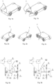
- Fig. 1a shows a perspective view of the autonomous mobile platform with two front active shields in closed position
- Fig. 1b shows a perspective view of the autonomous mobile platform with two front active shields in active position
- Fig. 2a shows a perspective view of the autonomous mobile platform with a side active shield in closed position
- Fig. 2b shows a perspective front view of the autonomous mobile platform with the side active shield in the active position
- Fig. 2c shows a perspective rear view of the autonomous mobile platform with the side active shield in active position
- Fig. 3a shows a control system of the active shield in closed position
- Fig. 3b shows the control system of the active shield in active position
- Fig. 1a shows a perspective view of the autonomous mobile platform with two front active shields in closed position
- Fig. 1b shows a perspective view of the autonomous mobile platform with two front active shields in active position
- Fig. 2a shows a perspective view of the autonomous mobile platform with a side active shield in closed position
- Fig. 2b shows a
- FIG. 4a shows a perspective view of the control system of a tiltable active shield in closed position
- Fig. 4b shows a perspective view of the control system of a tiltable active shield in active position
- Fig. 5 a top view of the autonomous mobile platform with two front active shields when passing between detected and identified inanimate easily movable obstacles in the planned path of the platform
- Fig. 6 shows a top view of the autonomous mobile platform with two front active shields while removing one detected and identified inanimate easily movable obstacle in the planned path of the platform
- Fig. 7 is a top view of the autonomous mobile platform as it passes between three fixed obstacles and one detected and identified inanimate easily movable obstacle in the platform path.
- the autonomous mobile platform comprises a chassis provided with wheels coupled to drives, which are part of the means for moving the autonomous mobile platform through a designated environment. These means are coupled to a known navigation and computing system 7 for controlling the motion of the autonomous mobile platform and for detecting and identifying obstacles in the planned path of the autonomous mobile platform in the environment in which it moves.
- the navigation and computing system 7 comprises a plurality of sensors for monitoring the situation around the autonomous mobile platform, signals of which are processed using various data processing techniques, such as using artificial intelligence.
- the navigation and computing system 7 is able to distinguish fixed obstacles that the autonomous mobile platform must avoid and inanimate easily movable obstacles which can be removed by the autonomous mobile platform from its planned path by means of active shields 1 , which are rotatably mounted on the circumference of the autonomous mobile platform.
- one active shield 1 is mounted on the circumference of the autonomous mobile platform, namely on one of its sides.
- two active shields 1 are mounted in the front part of the autonomous mobile platform. It is clear from the combination of these embodiments that the autonomous mobile platform can be provided with two active shields 1 in the front part, two active shields 1 in the rear part and one active shield 1 on each side. In an alternative embodiment, one active shield 1 can be mounted in the front and rear parts over the entire width of the autonomous mobile platform.
- the active shield 1_ comprises a planar plate which is rotatably mounted in a known manner on a fixed structure 6 of the autonomous mobile platform, for example on a frame or body, by means of two hinges 2, the axis of rotation of the active shield 1 being vertical.
- the plate of the active shield 1 is coupled to a movable part of the actuator 5 , which can be formed, for example, by a double-acting hydraulic or pneumatic cylinder or a linear electric actuator with a rotating screw.
- the static part of the actuator 5 is coupled to the fixed structure 6 of the autonomous mobile platform, for example the frame or the body.
- the actuator 5 is coupled to the navigation and computing system 7, which is connected to a power source 8 used to power the navigation and computing system 7 and to power the actuator 5 or its control system.
- the static part 51 of the actuator 5 is connected to the fixed structure 6 of the autonomous mobile platform rotatably by means of a hinge 4 of the static part of the actuator 5, which is attached to the fixed structure 6 of the autonomous mobile platform.
- a pin is mounted in the hinge 4 of the static part 51 of the actuator 5, the pin secures in the hinge 4 an eye formed on the static part 51 of the actuator 5.
- the rotatable mounting of the static part 51 of the actuator 5 on the fixed structure of the autonomous mobile platform can also be formed in another suitable known manner, for example by a joint.
- the movable part 52 of the actuator 5 is connected to the plate of the active shield 1 rotatably by means of a hinge 3 of the movable part 52 of the actuator 5, which is fixedly mounted on the inner side of the plate of the active shield 1 .
- a pin is mounted in the hinge 3 of the movable part 52 of the actuator 5, the pin secures in the hinge 3 an eye formed on the movable part 52 of the actuator 5.
- the rotatable mounting of the movable part 52 of the actuator 5 on the fixed structure of the autonomous mobile platform can also be formed in another suitable known manner, for example by a joint.
- the navigation and computing system 7 of the autonomous mobile platform creates, based on the coordinates or other parameters entered, a plan of the path along which the autonomous mobile platform is to move in the given environment.
- the navigation and computing system 7 monitors the surroundings of the autonomous mobile platform using various sensor systems and various techniques for processing the data collected by the sensors, such as artificial intelligence data processing.
- the navigation and computing system 7 evaluates which of the active shields 1 can be used to remove the obstacle and the actuator 5 of the relevant active shield 1 issues a command to initiate action.
- the active shield 1 starts to rotate and moves the obstacle out of the planned path of the autonomous mobile platform.
- the movable part 52 of the actuator 5 starts to extend in a direction away from the fixed structure of the autonomous mobile platform, the eye of the movable part 52 of the actuator rests on the hinge 3 pin of the movable part 52 of the actuator 5 and thus exerts a force on the plate of the active shield 1 .
- the plate of the active shield 1 begins to rotate in the axis 2 of the hinges 2 of the plate of the active shield 1 in a direction away from the fixed structure 6 of the autonomous mobile platform (see Figs. 3b , 4b ) so as to extend beyond the contour of the fixed structure 6 of the platform.
- the final position of the extension of the movable part 52 of the actuator 5 and the position of the plate relative to the fixed structure 6, as well as the time of extension of the movable part 52 of the actuator 5, is controlled by the navigation and computing system 7 of the platform, which performs, in addition to observing and evaluating the situation around the autonomous mobile platform by means of various sensors and various techniques for processing the data collected by the sensors, also the evaluation of the position of the movable part 52 of the actuator 5.
- the navigation and computing system 7 monitors the danger of exceeding the adjustable limit force for the motion of the actuator 5 from the current energy consumption by the energy source 7 for the motion of the actuator 5 and in the event of exceeding this force, the navigation and computing system 7 stops the motion of the actuator 5, returns it to its original position and issues a command to the autonomous mobile platform to avoid the obstacle which could not be removed.
- the rotation of the plate of the active shield 1 back to the tilted position see Figs.
- FIG. 5 shows the autonomous mobile platform in a left to right direction when approaching two obstacles which were detected by the navigation and computing system 7 and identified as inanimate and easily movable, for example, two piles of leaves or waste.
- the navigation and computing system 7 issues a command to start the actuators 5 of the two active shields 1 , as shown in the middle, and the obstacles are moved by the front active shields 1 out of the planned path of the autonomous mobile platform, which continues to move forward along the original planned path, as shown on the right-hand side.
- Fig. 6 shows the autonomous mobile platform moving along a circular path.
- the left part of Fig. 6 shows the arrival of the platform at the obstacle which is situated in front of the right-hand side of the platform and was detected by the navigation and computing system 7 and identified as inanimate and easily movable, for example, a box or packaging of goods.
- the navigation and computing system 7 issues a command to start the operation of the actuator 5 of the right-hand active shield 1_, which by its rotation removes the obstacle from the platform path, as shown on the right-hand side, and the platform can continue moving along its planned path.
- Fig. 7 shows on the left-hand side the arrival of the autonomous mobile platform at three fixed obstacles which are situated in the planned path of the platform, are detected by the navigation and computing system 7 and identified as fixed obstacles to be avoided.
- the navigation and computing system 7 detects and identifies an inanimate easily movable obstacle, which is situated on the right-hand side of the path of the platform as it avoids the fixed obstacles.
- the navigation and computing system 7 of the autonomous mobile platform issues a command to start the actuator 5 of the right-hand active shield 1 , which by its rotation moves the easily movable obstacle out of the path of the platform as it gets around the fixed obstacles, after which the platform passes through the section and continues moving along the planned path.
- the autonomous mobile platform with at least one active shield is capable of exerting force on the vehicle-identified easily movable inanimate obstacles (snow, soil, waste, etc.) and objects (boxes, packaging, bushes, curtains in construction openings, tarpaulins, etc.) in an environment proximate to the autonomous mobile platform, which allows to choose a more advantageous and shorter trajectory of the motion of the autonomous mobile platform which will not have to avoid the identified inanimate easily movable obstacle or object in the vicinity of the vehicle, but can move it by exerting direct force with the appropriate direction of force (push away, shove, move, etc.) to a position more advantageous to achieve the goal of the autonomous mobile platform along the planned path.
Landscapes
- Engineering & Computer Science (AREA)
- Robotics (AREA)
- Mechanical Engineering (AREA)
- Control Of Position, Course, Altitude, Or Attitude Of Moving Bodies (AREA)
Claims (4)
- Autonome mobile Plattform, die Mittel zum Bewegen der autonomen mobilen Plattform auf einer bestimmten Umgebung aufweist, die mit einem Navigations- und Rechensystem gekoppelt sind, um die Bewegung der autonomen mobilen Plattform zu steuern und Hindernisse in der geplanten Bahn in der Umgebung zu erkennen und zu identifizieren, in der sie sich bewegt, dadurch gekennzeichnet, dass auf dem Umfang der autonomen mobilen Plattform mindestens ein aktiver Schild (1) drehbar gelagert ist, der mit einem Aktuator (5) zum Veranlassen einer Drehbewegung des aktiven Schildes (1) zum Verschieben eines durch das Rechensystem (7) identifizierten und erkannten unbelebten, einfach verlegbaren Hindernisses außerhalb der geplanten Bahn der autonomen mobilen Plattform gekoppelt ist, wobei das jeweilige Hindernis auf dem Untergrund der Umgebung verlegt wird, auf dem sich die autonome mobile Plattform bewegt.
- Autonome mobile Plattform nach dem Anspruch 1, dadurch gekennzeichnet, dass der aktive Schild (1) eine in einer Aufhängung (2) drehbar gelagerte Platte aufweist, die an der festen Konstruktion (6) der autonomen mobilen Plattform fest gelagert ist, wobei die Drehachse des aktiven Schildes senkrecht ist und die Außenfläche der Platte mit dem unbelebten, einfach verlegbaren Hindernis im Kontakt steht.
- Autonome mobile Plattform nach dem Anspruch 2, dadurch gekennzeichnet, dass die Platte des aktiven Schildes (1) mit dem beweglichen Teil des Aktuators (5) gekoppelt ist, dessen statischer Teil mit der festen Konstruktion (6) der autonomen mobilen Plattform gekoppelt ist.
- Autonome mobile Plattform nach einem der vorangehenden Ansprüche, dadurch gekennzeichnet, dass das Rechensystem (7) die Mittel zur Überwachung der Grenzkraft für die Bewegung des Aktuators (5) beim Verlegen des Hindernisses aufweist und bei deren Überschreitung ein Befehl zum Zurückfahren des Aktuators (5) und zum Umfahren des Hindernisses ausgibt.
Applications Claiming Priority (1)
| Application Number | Priority Date | Filing Date | Title |
|---|---|---|---|
| PCT/CZ2021/050122 WO2023072319A1 (en) | 2021-11-01 | 2021-11-01 | Autonomous mobile platform |
Publications (3)
| Publication Number | Publication Date |
|---|---|
| EP4294602A1 EP4294602A1 (de) | 2023-12-27 |
| EP4294602B1 true EP4294602B1 (de) | 2025-01-01 |
| EP4294602C0 EP4294602C0 (de) | 2025-01-01 |
Family
ID=79021035
Family Applications (1)
| Application Number | Title | Priority Date | Filing Date |
|---|---|---|---|
| EP21830382.4A Active EP4294602B1 (de) | 2021-11-01 | 2021-11-01 | Autonome mobile plattform |
Country Status (2)
| Country | Link |
|---|---|
| EP (1) | EP4294602B1 (de) |
| WO (1) | WO2023072319A1 (de) |
Family Cites Families (2)
| Publication number | Priority date | Publication date | Assignee | Title |
|---|---|---|---|---|
| US9682483B1 (en) * | 2015-03-19 | 2017-06-20 | Amazon Technologies, Inc. | Systems and methods for removing debris from warehouse floors |
| US9827677B1 (en) * | 2016-05-16 | 2017-11-28 | X Development Llc | Robotic device with coordinated sweeping tool and shovel tool |
-
2021
- 2021-11-01 EP EP21830382.4A patent/EP4294602B1/de active Active
- 2021-11-01 WO PCT/CZ2021/050122 patent/WO2023072319A1/en not_active Ceased
Also Published As
| Publication number | Publication date |
|---|---|
| WO2023072319A1 (en) | 2023-05-04 |
| EP4294602A1 (de) | 2023-12-27 |
| EP4294602C0 (de) | 2025-01-01 |
Similar Documents
| Publication | Publication Date | Title |
|---|---|---|
| US10906187B2 (en) | Robotic gripper camera | |
| US10843331B2 (en) | Mounting a sensor module to an unmanned ground vehicle | |
| JP7143451B2 (ja) | 自律的に動作する作業機械を動作させるための方法及び装置 | |
| CA3032756C (en) | Unmanned ground vehicle with compact manipulator stowing | |
| US10626576B2 (en) | Loader with telescopic lift arm | |
| US6866465B2 (en) | Robotic system and method for collecting and dispensing regular and irregular shaped objects | |
| EP3812250A1 (de) | Nutzfahrzeug | |
| JP2022542216A (ja) | 移動ロボットセンサ構成 | |
| JP2024536084A (ja) | トレーラ及びコンテナから製品を荷降ろし/荷広げするロボットトラックアンローダのための認識ベースロボット操作システム及び方法 | |
| US11427986B2 (en) | Door activated interlock system for a work vehicle | |
| JP2010122916A (ja) | 自律移動装置 | |
| EP4294602B1 (de) | Autonome mobile plattform | |
| EP3639644B1 (de) | Robotisches landwirtschaftliches fahrzeug mit sicherheitsmassnahmen | |
| JPS61501969A (ja) | ボデイに支持されかつ丁番結合されたおよび/または滑動する部材を開きおよび/または閉じるためのマニピユレ−タおよび方法 | |
| CN223672663U (zh) | 一种智能避障工地无人运输机器人 | |
| RU210916U1 (ru) | Роботизированное грузовое транспортное средство | |
| KR101229025B1 (ko) | 다관절식 매니퓰레이터가 장착된 로봇 플랫폼 | |
| JP2024112908A (ja) | トレーラ及びコンテナから製品を荷降ろし/荷広げするロボットトラックアンローダのための認識ベースロボット操作システム及び方法 | |
| WO2023048592A1 (ru) | Роботизированное грузовое транспортное средство | |
| AU2001240771A1 (en) | Lifting tail gate retractable under the floor of a motor vehicle or the like |
Legal Events
| Date | Code | Title | Description |
|---|---|---|---|
| STAA | Information on the status of an ep patent application or granted ep patent |
Free format text: STATUS: UNKNOWN |
|
| STAA | Information on the status of an ep patent application or granted ep patent |
Free format text: STATUS: THE INTERNATIONAL PUBLICATION HAS BEEN MADE |
|
| PUAI | Public reference made under article 153(3) epc to a published international application that has entered the european phase |
Free format text: ORIGINAL CODE: 0009012 |
|
| STAA | Information on the status of an ep patent application or granted ep patent |
Free format text: STATUS: REQUEST FOR EXAMINATION WAS MADE |
|
| 17P | Request for examination filed |
Effective date: 20230921 |
|
| AK | Designated contracting states |
Kind code of ref document: A1 Designated state(s): AL AT BE BG CH CY CZ DE DK EE ES FI FR GB GR HR HU IE IS IT LI LT LU LV MC MK MT NL NO PL PT RO RS SE SI SK SM TR |
|
| GRAP | Despatch of communication of intention to grant a patent |
Free format text: ORIGINAL CODE: EPIDOSNIGR1 |
|
| STAA | Information on the status of an ep patent application or granted ep patent |
Free format text: STATUS: GRANT OF PATENT IS INTENDED |
|
| INTG | Intention to grant announced |
Effective date: 20241010 |
|
| GRAS | Grant fee paid |
Free format text: ORIGINAL CODE: EPIDOSNIGR3 |
|
| GRAA | (expected) grant |
Free format text: ORIGINAL CODE: 0009210 |
|
| STAA | Information on the status of an ep patent application or granted ep patent |
Free format text: STATUS: THE PATENT HAS BEEN GRANTED |
|
| AK | Designated contracting states |
Kind code of ref document: B1 Designated state(s): AL AT BE BG CH CY CZ DE DK EE ES FI FR GB GR HR HU IE IS IT LI LT LU LV MC MK MT NL NO PL PT RO RS SE SI SK SM TR |
|
| DAV | Request for validation of the european patent (deleted) | ||
| DAX | Request for extension of the european patent (deleted) | ||
| REG | Reference to a national code |
Ref country code: GB Ref legal event code: FG4D |
|
| REG | Reference to a national code |
Ref country code: DE Ref legal event code: R096 Ref document number: 602021024444 Country of ref document: DE |
|
| REG | Reference to a national code |
Ref country code: CH Ref legal event code: EP |
|
| REG | Reference to a national code |
Ref country code: IE Ref legal event code: FG4D |
|
| U01 | Request for unitary effect filed |
Effective date: 20250129 |
|
| U07 | Unitary effect registered |
Designated state(s): AT BE BG DE DK EE FI FR IT LT LU LV MT NL PT RO SE SI Effective date: 20250204 |
|
| PG25 | Lapsed in a contracting state [announced via postgrant information from national office to epo] |
Ref country code: PL Free format text: LAPSE BECAUSE OF FAILURE TO SUBMIT A TRANSLATION OF THE DESCRIPTION OR TO PAY THE FEE WITHIN THE PRESCRIBED TIME-LIMIT Effective date: 20250101 |
|
| PG25 | Lapsed in a contracting state [announced via postgrant information from national office to epo] |
Ref country code: ES Free format text: LAPSE BECAUSE OF FAILURE TO SUBMIT A TRANSLATION OF THE DESCRIPTION OR TO PAY THE FEE WITHIN THE PRESCRIBED TIME-LIMIT Effective date: 20250101 |
|
| PG25 | Lapsed in a contracting state [announced via postgrant information from national office to epo] |
Ref country code: IS Free format text: LAPSE BECAUSE OF FAILURE TO SUBMIT A TRANSLATION OF THE DESCRIPTION OR TO PAY THE FEE WITHIN THE PRESCRIBED TIME-LIMIT Effective date: 20250501 Ref country code: NO Free format text: LAPSE BECAUSE OF FAILURE TO SUBMIT A TRANSLATION OF THE DESCRIPTION OR TO PAY THE FEE WITHIN THE PRESCRIBED TIME-LIMIT Effective date: 20250401 |
|
| PG25 | Lapsed in a contracting state [announced via postgrant information from national office to epo] |
Ref country code: HR Free format text: LAPSE BECAUSE OF FAILURE TO SUBMIT A TRANSLATION OF THE DESCRIPTION OR TO PAY THE FEE WITHIN THE PRESCRIBED TIME-LIMIT Effective date: 20250101 |
|
| PG25 | Lapsed in a contracting state [announced via postgrant information from national office to epo] |
Ref country code: GR Free format text: LAPSE BECAUSE OF FAILURE TO SUBMIT A TRANSLATION OF THE DESCRIPTION OR TO PAY THE FEE WITHIN THE PRESCRIBED TIME-LIMIT Effective date: 20250402 |
|
| PG25 | Lapsed in a contracting state [announced via postgrant information from national office to epo] |
Ref country code: CZ Free format text: LAPSE BECAUSE OF FAILURE TO SUBMIT A TRANSLATION OF THE DESCRIPTION OR TO PAY THE FEE WITHIN THE PRESCRIBED TIME-LIMIT Effective date: 20250101 |
|
| PG25 | Lapsed in a contracting state [announced via postgrant information from national office to epo] |
Ref country code: SM Free format text: LAPSE BECAUSE OF FAILURE TO SUBMIT A TRANSLATION OF THE DESCRIPTION OR TO PAY THE FEE WITHIN THE PRESCRIBED TIME-LIMIT Effective date: 20250101 |
|
| PG25 | Lapsed in a contracting state [announced via postgrant information from national office to epo] |
Ref country code: SK Free format text: LAPSE BECAUSE OF FAILURE TO SUBMIT A TRANSLATION OF THE DESCRIPTION OR TO PAY THE FEE WITHIN THE PRESCRIBED TIME-LIMIT Effective date: 20250101 |
|
| PLBE | No opposition filed within time limit |
Free format text: ORIGINAL CODE: 0009261 |
|
| STAA | Information on the status of an ep patent application or granted ep patent |
Free format text: STATUS: NO OPPOSITION FILED WITHIN TIME LIMIT |
|
| 26N | No opposition filed |
Effective date: 20251002 |
|
| U20 | Renewal fee for the european patent with unitary effect paid |
Year of fee payment: 5 Effective date: 20251107 |