EP4294594B1 - Method for operating a machine for laser machining of tubes and profiled sections with an automatic system for the application of threaded inserts integrated in the machine - Google Patents
Method for operating a machine for laser machining of tubes and profiled sections with an automatic system for the application of threaded inserts integrated in the machine Download PDFInfo
- Publication number
- EP4294594B1 EP4294594B1 EP22706122.3A EP22706122A EP4294594B1 EP 4294594 B1 EP4294594 B1 EP 4294594B1 EP 22706122 A EP22706122 A EP 22706122A EP 4294594 B1 EP4294594 B1 EP 4294594B1
- Authority
- EP
- European Patent Office
- Prior art keywords
- insert
- picking
- tube
- threaded
- riveter
- Prior art date
- Legal status (The legal status is an assumption and is not a legal conclusion. Google has not performed a legal analysis and makes no representation as to the accuracy of the status listed.)
- Active
Links
Images




Classifications
-
- B—PERFORMING OPERATIONS; TRANSPORTING
- B23—MACHINE TOOLS; METAL-WORKING NOT OTHERWISE PROVIDED FOR
- B23K—SOLDERING OR UNSOLDERING; WELDING; CLADDING OR PLATING BY SOLDERING OR WELDING; CUTTING BY APPLYING HEAT LOCALLY, e.g. FLAME CUTTING; WORKING BY LASER BEAM
- B23K26/00—Working by laser beam, e.g. welding, cutting or boring
- B23K26/36—Removing material
- B23K26/38—Removing material by boring or cutting
-
- B—PERFORMING OPERATIONS; TRANSPORTING
- B21—MECHANICAL METAL-WORKING WITHOUT ESSENTIALLY REMOVING MATERIAL; PUNCHING METAL
- B21J—FORGING; HAMMERING; PRESSING METAL; RIVETING; FORGE FURNACES
- B21J15/00—Riveting
- B21J15/10—Riveting machines
- B21J15/14—Riveting machines specially adapted for riveting specific articles, e.g. brake lining machines
- B21J15/142—Aerospace structures
-
- B—PERFORMING OPERATIONS; TRANSPORTING
- B21—MECHANICAL METAL-WORKING WITHOUT ESSENTIALLY REMOVING MATERIAL; PUNCHING METAL
- B21J—FORGING; HAMMERING; PRESSING METAL; RIVETING; FORGE FURNACES
- B21J15/00—Riveting
- B21J15/10—Riveting machines
- B21J15/30—Particular elements, e.g. supports; Suspension equipment specially adapted for portable riveters
- B21J15/32—Devices for inserting or holding rivets in position with or without feeding arrangements
-
- B—PERFORMING OPERATIONS; TRANSPORTING
- B23—MACHINE TOOLS; METAL-WORKING NOT OTHERWISE PROVIDED FOR
- B23K—SOLDERING OR UNSOLDERING; WELDING; CLADDING OR PLATING BY SOLDERING OR WELDING; CUTTING BY APPLYING HEAT LOCALLY, e.g. FLAME CUTTING; WORKING BY LASER BEAM
- B23K26/00—Working by laser beam, e.g. welding, cutting or boring
- B23K26/0093—Working by laser beam, e.g. welding, cutting or boring combined with mechanical machining or metal-working covered by other subclasses than B23K
-
- B—PERFORMING OPERATIONS; TRANSPORTING
- B23—MACHINE TOOLS; METAL-WORKING NOT OTHERWISE PROVIDED FOR
- B23K—SOLDERING OR UNSOLDERING; WELDING; CLADDING OR PLATING BY SOLDERING OR WELDING; CUTTING BY APPLYING HEAT LOCALLY, e.g. FLAME CUTTING; WORKING BY LASER BEAM
- B23K26/00—Working by laser beam, e.g. welding, cutting or boring
- B23K26/08—Devices involving relative movement between laser beam and workpiece
- B23K26/083—Devices involving movement of the workpiece in at least one axial direction
- B23K26/0838—Devices involving movement of the workpiece in at least one axial direction by using an endless conveyor belt
- B23K26/0846—Devices involving movement of the workpiece in at least one axial direction by using an endless conveyor belt for moving elongated workpieces longitudinally, e.g. wire or strip material
-
- B—PERFORMING OPERATIONS; TRANSPORTING
- B23—MACHINE TOOLS; METAL-WORKING NOT OTHERWISE PROVIDED FOR
- B23K—SOLDERING OR UNSOLDERING; WELDING; CLADDING OR PLATING BY SOLDERING OR WELDING; CUTTING BY APPLYING HEAT LOCALLY, e.g. FLAME CUTTING; WORKING BY LASER BEAM
- B23K26/00—Working by laser beam, e.g. welding, cutting or boring
- B23K26/08—Devices involving relative movement between laser beam and workpiece
- B23K26/0869—Devices involving movement of the laser head in at least one axial direction
- B23K26/0876—Devices involving movement of the laser head in at least one axial direction in at least two axial directions
-
- B—PERFORMING OPERATIONS; TRANSPORTING
- B23—MACHINE TOOLS; METAL-WORKING NOT OTHERWISE PROVIDED FOR
- B23K—SOLDERING OR UNSOLDERING; WELDING; CLADDING OR PLATING BY SOLDERING OR WELDING; CUTTING BY APPLYING HEAT LOCALLY, e.g. FLAME CUTTING; WORKING BY LASER BEAM
- B23K26/00—Working by laser beam, e.g. welding, cutting or boring
- B23K26/36—Removing material
- B23K26/38—Removing material by boring or cutting
- B23K26/382—Removing material by boring or cutting by boring
-
- B—PERFORMING OPERATIONS; TRANSPORTING
- B23—MACHINE TOOLS; METAL-WORKING NOT OTHERWISE PROVIDED FOR
- B23P—METAL-WORKING NOT OTHERWISE PROVIDED FOR; COMBINED OPERATIONS; UNIVERSAL MACHINE TOOLS
- B23P23/00—Machines or arrangements of machines for performing specified combinations of different metal-working operations not covered by a single other subclass
- B23P23/04—Machines or arrangements of machines for performing specified combinations of different metal-working operations not covered by a single other subclass for both machining and other metal-working operations
-
- B—PERFORMING OPERATIONS; TRANSPORTING
- B25—HAND TOOLS; PORTABLE POWER-DRIVEN TOOLS; MANIPULATORS
- B25B—TOOLS OR BENCH DEVICES NOT OTHERWISE PROVIDED FOR, FOR FASTENING, CONNECTING, DISENGAGING, OR HOLDING
- B25B27/00—Hand tools, specially adapted for fitting together or separating parts or objects whether or not involving some deformation, not otherwise provided for
- B25B27/0007—Tools for fixing internally screw-threaded tubular fasteners
- B25B27/0014—Tools for fixing internally screw-threaded tubular fasteners motor-driven
-
- F—MECHANICAL ENGINEERING; LIGHTING; HEATING; WEAPONS; BLASTING
- F16—ENGINEERING ELEMENTS AND UNITS; GENERAL MEASURES FOR PRODUCING AND MAINTAINING EFFECTIVE FUNCTIONING OF MACHINES OR INSTALLATIONS; THERMAL INSULATION IN GENERAL
- F16B—DEVICES FOR FASTENING OR SECURING CONSTRUCTIONAL ELEMENTS OR MACHINE PARTS TOGETHER, e.g. NAILS, BOLTS, CIRCLIPS, CLAMPS, CLIPS OR WEDGES; JOINTS OR JOINTING
- F16B37/00—Nuts or like thread-engaging members
- F16B37/04—Devices for fastening nuts to surfaces, e.g. sheets, plates
- F16B37/06—Devices for fastening nuts to surfaces, e.g. sheets, plates by means of welding or riveting
- F16B37/062—Devices for fastening nuts to surfaces, e.g. sheets, plates by means of welding or riveting by means of riveting
- F16B37/065—Devices for fastening nuts to surfaces, e.g. sheets, plates by means of welding or riveting by means of riveting by deforming the material of the nut
- F16B37/067—Devices for fastening nuts to surfaces, e.g. sheets, plates by means of welding or riveting by means of riveting by deforming the material of the nut the material of the nut being deformed by a threaded member generating axial movement of the threaded part of the nut, e.g. blind rivet type
-
- B—PERFORMING OPERATIONS; TRANSPORTING
- B23—MACHINE TOOLS; METAL-WORKING NOT OTHERWISE PROVIDED FOR
- B23K—SOLDERING OR UNSOLDERING; WELDING; CLADDING OR PLATING BY SOLDERING OR WELDING; CUTTING BY APPLYING HEAT LOCALLY, e.g. FLAME CUTTING; WORKING BY LASER BEAM
- B23K2101/00—Articles made by soldering, welding or cutting
- B23K2101/04—Tubular or hollow articles
- B23K2101/06—Tubes
-
- B—PERFORMING OPERATIONS; TRANSPORTING
- B23—MACHINE TOOLS; METAL-WORKING NOT OTHERWISE PROVIDED FOR
- B23K—SOLDERING OR UNSOLDERING; WELDING; CLADDING OR PLATING BY SOLDERING OR WELDING; CUTTING BY APPLYING HEAT LOCALLY, e.g. FLAME CUTTING; WORKING BY LASER BEAM
- B23K2101/00—Articles made by soldering, welding or cutting
- B23K2101/28—Beams
Definitions
- This invention relates to a machine for the laser cutting of tubes and profiled sections.
- tube and “profiled section” are used to identify any elongated article having (barring machining tolerances) a uniform cross section along its longitudinal axis, the cross section being of any shape, whether closed (e.g., circular, rectangular, or square) or open (e.g., L, C, U, etc.).
- longitudinal and “transverse” are used to identify the direction of the longitudinal axis of the tube or profiled section and respectively a direction orthogonal to the longitudinal direction.
- DE 102016106067 A1 describes a machine for the laser cutting of tubes or profiled sections configured to make threaded holes.
- the object of this invention is to provide a solution for reducing the production time of tubes and profiled sections equipped with threaded inserts.
- the machine for the laser machining of tubes and profiled sections that is the subject of this invention is described and illustrated herein with reference to its application for machining tubes, but it is understood that it is equally usable for machining profiled sections.
- the tubes or profiled sections on which the machine is able to work may have cross sections of different shapes and sizes.
- a machine for the laser machining of tubes comprises, in a manner known per se, a base 10, a working head 12 adapted to carry out a laser cutting process on a tube T (shown in Fig. 2 to 8 ), a supply device (not shown) adapted to advance the tube T along a longitudinal direction x (coincident with the direction of the longitudinal axis of the tube T and orthogonal to the page of the drawings of Fig. 2 to 8 ), a guide device (not shown) adapted to guide the tube T as it is moved forward by the supply device, and a scanning system (not shown) adapted to scan at least one portion (e.g., an upper portion) of the profile of the cross section of the tube T.
- the working head 12 comprises, in a manner known per se, a focusing device 18 adapted to emit a laser beam focused on the surface of the tube T.
- the working head 12 is carried by a head support structure 26.
- the head support structure 26, and thus with it also the working head 12, is mounted on a carriage 28 so as to be movable in the vertical direction (direction z).
- the carriage 28 is mounted so as to be translatable in a transverse direction (direction y) relative to the base 10 of the machine.
- the transverse direction y is a horizontal direction, it could also be a direction inclined at a certain angle to the horizontal (while obviously lying in a plane perpendicular to the longitudinal axis of the tube).
- the working head 12 is movable in the vertical transverse plane, i.e., in a plane perpendicular to the longitudinal axis x of the tube T, with two degrees of freedom, namely, with one degree of freedom of translation in the vertical direction and with one degree of freedom of translation in the transverse direction.
- the working head 12 may be mounted on the head support structure 26 so as to be able to oscillate about a transversely directed axis of oscillation (or, according to an embodiment not shown, about two axes of oscillation orthogonal to each other).
- the machine supply device is preferably arranged to drive not only a translational movement of the tube T along the direction of the longitudinal axis x (a forward movement or even a backward movement while working the workpiece), but also a rotation movement of the tube T about the longitudinal axis x.
- the machine further comprises an automatic insert application system, indicated collectively with 30.
- an automatic insert application system is configured to place a threaded insert I (shown in Fig. 9 and 10 ) into a corresponding hole or housing H preliminarily formed in a wall w of the tube or profiled section T by laser machining.
- the automatic insert application system 30 is integrated into the machine and is configured to operate in coordination with the working head 12.
- Inserts applicable with the machine according to the invention are, for example, standard inserts comprising a bushing body having an outer surface S with a polygonal cross section, in particular hexagonal, and a flange or head F formed at a proximal end of the bushing body.
- a threaded hole B is formed in the bushing body, which comprises a proximal segment B1 having a larger diameter and arranged at the head F, and a distal segment B2 having a smaller diameter and provided with a threading.
- Examples of standard inserts applicable with the machine according to the invention are open hexagonal inserts M4, M5, M6, M8 with cylindrical head, closed hexagonal inserts M4, M5, M6, M8 with cylindrical head, open hexagonal inserts M4, M5, M6, M8 with reduced head and closed hexagonal inserts M4, M5, M6, M8 with reduced head.
- Fig. 9 and 10 show an open hexagonal insert with a cylindrical head.
- the automatic insert application system 30 comprises a riveter 31 of a type known per se, said riveter provided with a threaded rotating pin 32 configured to engage the threaded hole B of the threaded insert I for gripping and placing the threaded insert I.
- the riveter 31 comprises, in a manner known per se, a motor or actuator 31a to drive the rotation of the threaded pin 32.
- the placement of the threaded insert I takes place by forcefully inserting, by means of the riveter 31, the threaded insert I into the housing H until the head F comes into contact with the wall w of the tube or profiled section T; subsequently, the riveter 31 is slightly extracted causing the deformation of a part of the insert comprised between the distal threaded segment B2 and the wall w of the tube or profiled section T and which has a reduced thickness due to the presence of the hole segment B1 of larger diameter (see Fig. 10 ); in this way the wall w of the tube or profiled section T is clamped between the head F and the deformed part of the threaded insert. Lastly, the riveter 31 is removed by unscrewing the threaded pin 32 from the threaded insert I so anchored.
- the riveter 31 is mounted on a support structure 33, which in turn is attached to the carriage 28.
- the riveter 31 thus moves together with the carriage 28, and thus also together with the working head 12.
- the riveter 31 is thus translationally integral with the working head 12 both in the transverse direction y and in the vertical direction z.
- the position of the riveter 31 will be precisely on the same plane yz (orthogonal to the axis x of the tube or profiled section) of the working head 12; in this way, after having cut the hole in the tube or profiled section T with the working head 12, by moving only the y and z axes it is possible to bring the riveter 31 to insert the insert I in the same hole without needing to move the tube or the profiled section T being worked and/or to move the riveter 31 with further controlled axes.
- a linear actuator 34 is interposed between the support structure 33 and the riveter 31, which is configured to move the riveter 31 relative to the carriage 28 and thus the working head 12 along a direction parallel to the z axis.
- the riveter 31 is movable between a rest position corresponding to an upper end position of the linear actuator 34 (shown in Fig. 1 and 2 ), and a working position corresponding to a lower end position of the linear actuator 34 (shown in Fig. 7 ).
- the stroke of the riveter 31 is represented by the arrow z2 in Fig. 2 to 8 .
- the insert picking seat 36 is configured to receive only one threaded insert I at a time and is also shaped to prevent the threaded insert received therein from rotating about its central axis.
- the picking carriage 35c is movable from the retracted position shown in Fig. 11 and 12 to a forward position shown in Fig. 2 to 8 ; an actuator 35d is intended for this movement.
- the picking carriage 35c in its forward position allows the metal insert I to be picked up by the riveter 31, in the manner that will be described below.
- a guide (not shown) is provided, arranged alongside the picking carriage 35c. The above configuration allows the insert picking seat 36 to receive inserts I individually, such that they may be processed by the riveter 31.
- the insert supply assembly 35 and the insert picking seat 36 are arranged next to the carriage 28 and thus the riveter 31.
- the carriage 28 is therefore configured to shuttle between the tube or profiled section T and the insert picking seat 36 to allow the riveter 31 to grip the threaded insert I from the insert picking seat 36 and allow the riveter 31 to place the threaded insert on the tube or profiled section T, between a hole cutting operation and a subsequent cutting operation carried out on the tube or profiled section T by the working head 12.
- hole cutting operation means an operation in which the hole or housing H is formed in the wall w of the tube or profiled section T.
- “Cutting operation” means more generally any laser cutting operation performed on the tube or profiled section T, including the aforesaid hole cutting.
- a presence sensor 35e such as a photocell, is also arranged configured to detect the presence of the threaded insert I in the insert picking seat 36 when the picking carriage 35c is found in its forward position.
- the position of the insert picking seat 36 with the picking carriage 35 in the forward position is shown with a dashed line in Fig. 12 .
- Fig. 2 shows a hole cutting step by means of laser cutting of the tube or profiled section T.
- a housing H is formed in the tube or profiled section T by means of the working head 12.
- the riveter 31 in the resting position remains out of the way, allowing the machine to work without limitations.
- Fig. 3 shows a preparation step for picking the insert I.
- the carriage 28 is moved from the tube or profiled section T to the insert picking seat 26.
- the riveter 31 is positioned vertically on the axis of the insert I, which is located in the insert picking seat 36 with the carriage 35c in the forward position.
- Fig. 4 shows a lowering step of the riveter 31 in the picking position.
- Fig. 5 shows an insert picking step.
- Fig. 6 shows a riveter exiting step with insert.
- the riveter 31 extracts the insert I from the insert picking seat 36 and is ready for the application step in the previously made hole or housing H.
- Fig. 7 shows an insert application step on the tube or profiled section being worked.
- the riveter 31 applies the insert I into the previously formed hole or housing H. Note that the riveter 31 is further moved to its lower end position or working position.
- the riveter 31 operates in the manner described above with reference to Fig. 9 and 10 .
- a step of returning to the cutting position is shown in Fig. 8 .
- the riveter 31 By raising the riveter 31 by means of the linear actuator 34 and appropriately moving the y and z axes of the carriage 28, it returns to the laser cutting step by means of the working head 12.
- the automatic controls of the machine described above comprise a procedure for checking the insert type and the proper picking of the insert from the insert picking seat.
- the presence sensor 35e is configured to change state due to the picking of the threaded insert I from the insert picking seat 36 and consequently provide a detection signal.
- the presence sensor 35e is a photocell operating on the insert I by reflection
- the presence sensor 35e may be in an energized state
- the presence sensor 35e may be in a de-energized state.
- the presence sensor 35e will de-energize at a precise height z depending on the type of insert being processed (expected picking height).
- expected picking height the height reached by the riveter 31 when the change in state of the presence sensor 35e is detected. If the detected picking height corresponds to the expected one, the subsequent steps taken are moving the carriage 28 and the riveter 31 for the application of the insert I on the tube or profiled section T. If, on the other hand, the detected picking height does not correspond to the expected picking height, it means that:
- the riveter 31 positions itself near the picking point where a small pneumatic clamp (not shown) is provided that grips the insert to be discarded and holds it so that the riveter 31 may be unscrewed therefrom; subsequently the clamp opens and the defective insert falls into a shaft intended for cutting waste (not shown) and the riveter 31 starts up again for a new picking.
- a small pneumatic clamp (not shown) is provided that grips the insert to be discarded and holds it so that the riveter 31 may be unscrewed therefrom; subsequently the clamp opens and the defective insert falls into a shaft intended for cutting waste (not shown) and the riveter 31 starts up again for a new picking.
- the automatic controls of the above-described machine further comprise a procedure for also checking the presence of the insert in the insert picking seat 36 with the picking carriage 35c in the forward position: it may occur, in fact, that, in the transition between the supply chute 35b and the selector carriage 35c, the insert does not descend and therefore the selector carriage 35c exits empty; in this case, the presence sensor 35e does not change state upon the arrival of the selector carriage 35c (because the insert is not present), and therefore orders a second picking attempt.
- Air blowers (not shown) arranged along the chute and blowing in the direction of descent may be provided to aid in the descent of the insert from the chute 35b.
- the automatic controls of the above-described machine further comprise a procedure for checking the correct insertion of the insert into the tube or profiled section.
- the machine introduces the insert I into the housing H, which has been previously cut by laser, it should find itself in the position shown in Fig. 7 .
- the automatic controls of the above-described machine further comprise a procedure for preparing the housing for the threaded insert by means of laser cutting.
- the application process of a threaded insert on a laser cutting system for tubes involves first removing the material from the tube or profiled section where the threaded insert is to be applied.
- Said area is defined as the housing of the threaded insert.
- the removal of the material to form the housing is carried out by laser machining.
- Such machining is referred to as preparatory laser geometry.
- Preparatory laser geometry involves cutting a polygonal geometry, in particular hexagonal, oriented in a manner consistent with the orientation assumed by the threaded insert during the selection and picking process. This orientation is preserved by the riveter 31 and is always the same to ensure proper insertion of the threaded insert into the housing.
- a threaded insert is described by means of a series of geometric parameters that also allow the machine to know the size and shape of the housing.
- the machine performs the preparatory geometry automatically, with the position reference determined by the placeholder. If needed, the user has the possibility to parametrically adjust the dimensions and apply particular laser cutting parameters.
Landscapes
- Engineering & Computer Science (AREA)
- Physics & Mathematics (AREA)
- Optics & Photonics (AREA)
- Mechanical Engineering (AREA)
- Plasma & Fusion (AREA)
- General Engineering & Computer Science (AREA)
- Laser Beam Processing (AREA)
- Automatic Assembly (AREA)
Description
- This invention relates to a machine for the laser cutting of tubes and profiled sections.
- In the following description and claims, the terms "tube" and "profiled section" are used to identify any elongated article having (barring machining tolerances) a uniform cross section along its longitudinal axis, the cross section being of any shape, whether closed (e.g., circular, rectangular, or square) or open (e.g., L, C, U, etc.). In addition, the terms "longitudinal" and "transverse" are used to identify the direction of the longitudinal axis of the tube or profiled section and respectively a direction orthogonal to the longitudinal direction.
-
DE 102016106067 A1 describes a machine for the laser cutting of tubes or profiled sections configured to make threaded holes. - It is well known that, in the case of tubes or profiled sections having relatively thin walls, instead of making a threaded hole directly in the wall of the tube or profiled section, a threaded insert is sometimes applied in a housing made in the wall of the tube or profiled section. Said threaded insert bears the required threaded hole.
FR 2313998 A1 DE 102004006407 A1 describes a machine for making chip removal holes and equipped with an insert application system. - In known machines for the laser cutting of tubes and profiled sections, the workpieces produced by the machine must be picked up for the manual insertion of threaded inserts by an operator, or for insertion of said inserts by an offline machine. This situation thus leads to relatively long production times.
- The object of this invention is to provide a solution for reducing the production time of tubes and profiled sections equipped with threaded inserts.
- This and other objects are fully achieved according to this invention by a method for the operation of a machine for the laser cutting of tubes and profiled sections having the features specified in the appended independent claim 1.
- Advantageous embodiments of the invention are the subject of the dependent claims, the content of which is to be understood as an integral and integrating part of the following description.
- Due to such a method, a system fully integrated in the machine is used which allows threaded inserts of various sizes to be inserted into the tube or profiled section, previously cut with the laser; in this way the machine no longer produces only laser-cut pieces that must then be reworked to insert the inserts but rather finished workpieces ready for use.
- There is therefore a clear reduction in production time.
- Further features and advantages of this invention will become clear from the detailed description that follows, given purely by way of non-limiting example with reference to the accompanying drawings, wherein:
-
Fig. 1 is a perspective view partially showing a machine for the laser machining of tubes or profiled sections provided with an automatic insert application system according to an embodiment of this invention; -
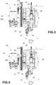
Fig. 2 to 8 are front elevation views representing the machine inFig. 1 in different stages of operation; -
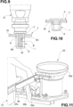
Fig. 9 is a front elevation view depicting a riveter of the machine inFig. 1 while placing a threaded insert on a tube or profiled section; -
Fig. 10 is a front elevation view representing the threaded insert applied on the tube or profiled section; and -
Fig. 11 and12 are perspective views representing a part of the automatic insert application system of the machine inFig. 1 . - The machine for the laser machining of tubes and profiled sections that is the subject of this invention is described and illustrated herein with reference to its application for machining tubes, but it is understood that it is equally usable for machining profiled sections. The tubes or profiled sections on which the machine is able to work may have cross sections of different shapes and sizes.
- Referring to the figures, a machine for the laser machining of tubes according to an embodiment of this invention comprises, in a manner known per se, a
base 10, a workinghead 12 adapted to carry out a laser cutting process on a tube T (shown inFig. 2 to 8 ), a supply device (not shown) adapted to advance the tube T along a longitudinal direction x (coincident with the direction of the longitudinal axis of the tube T and orthogonal to the page of the drawings ofFig. 2 to 8 ), a guide device (not shown) adapted to guide the tube T as it is moved forward by the supply device, and a scanning system (not shown) adapted to scan at least one portion (e.g., an upper portion) of the profile of the cross section of the tube T. - The working
head 12 comprises, in a manner known per se, a focusingdevice 18 adapted to emit a laser beam focused on the surface of the tube T. The workinghead 12 is carried by ahead support structure 26. Thehead support structure 26, and thus with it also the workinghead 12, is mounted on acarriage 28 so as to be movable in the vertical direction (direction z). In turn, thecarriage 28 is mounted so as to be translatable in a transverse direction (direction y) relative to thebase 10 of the machine. Although in the embodiment shown in the figures the transverse direction y is a horizontal direction, it could also be a direction inclined at a certain angle to the horizontal (while obviously lying in a plane perpendicular to the longitudinal axis of the tube). Thus, the workinghead 12 is movable in the vertical transverse plane, i.e., in a plane perpendicular to the longitudinal axis x of the tube T, with two degrees of freedom, namely, with one degree of freedom of translation in the vertical direction and with one degree of freedom of translation in the transverse direction. Further, as provided in the illustrated example embodiment, the workinghead 12 may be mounted on thehead support structure 26 so as to be able to oscillate about a transversely directed axis of oscillation (or, according to an embodiment not shown, about two axes of oscillation orthogonal to each other). - The machine supply device is preferably arranged to drive not only a translational movement of the tube T along the direction of the longitudinal axis x (a forward movement or even a backward movement while working the workpiece), but also a rotation movement of the tube T about the longitudinal axis x. In the case of a laser cutting machine for tubes, the combination of the degrees of freedom of movement of the working head 12 (translation along the vertical direction z, translation along the transverse direction y, rotation about the axis of oscillation and, possibly, translation also along the direction of the longitudinal axis x) and the degrees of freedom of movement of the tube T (translation along the direction of the longitudinal axis x and rotation about the longitudinal axis x) makes it possible to make a cut on the wall of the tube T along any cutting line.
- The machine further comprises an automatic insert application system, indicated collectively with 30. Such a system is configured to place a threaded insert I (shown in
Fig. 9 and 10 ) into a corresponding hole or housing H preliminarily formed in a wall w of the tube or profiled section T by laser machining. The automaticinsert application system 30 is integrated into the machine and is configured to operate in coordination with the workinghead 12. - Inserts applicable with the machine according to the invention are, for example, standard inserts comprising a bushing body having an outer surface S with a polygonal cross section, in particular hexagonal, and a flange or head F formed at a proximal end of the bushing body. A threaded hole B is formed in the bushing body, which comprises a proximal segment B1 having a larger diameter and arranged at the head F, and a distal segment B2 having a smaller diameter and provided with a threading. Examples of standard inserts applicable with the machine according to the invention are open hexagonal inserts M4, M5, M6, M8 with cylindrical head, closed hexagonal inserts M4, M5, M6, M8 with cylindrical head, open hexagonal inserts M4, M5, M6, M8 with reduced head and closed hexagonal inserts M4, M5, M6, M8 with reduced head.
Fig. 9 and 10 show an open hexagonal insert with a cylindrical head. - The automatic
insert application system 30 comprises ariveter 31 of a type known per se, said riveter provided with a threaded rotatingpin 32 configured to engage the threaded hole B of the threaded insert I for gripping and placing the threaded insert I. To this end, theriveter 31 comprises, in a manner known per se, a motor oractuator 31a to drive the rotation of the threadedpin 32. The placement of the threaded insert I takes place by forcefully inserting, by means of theriveter 31, the threaded insert I into the housing H until the head F comes into contact with the wall w of the tube or profiled section T; subsequently, theriveter 31 is slightly extracted causing the deformation of a part of the insert comprised between the distal threaded segment B2 and the wall w of the tube or profiled section T and which has a reduced thickness due to the presence of the hole segment B1 of larger diameter (seeFig. 10 ); in this way the wall w of the tube or profiled section T is clamped between the head F and the deformed part of the threaded insert. Lastly, theriveter 31 is removed by unscrewing the threadedpin 32 from the threaded insert I so anchored. - The
riveter 31 is mounted on asupport structure 33, which in turn is attached to thecarriage 28. Theriveter 31 thus moves together with thecarriage 28, and thus also together with the workinghead 12. Theriveter 31 is thus translationally integral with the workinghead 12 both in the transverse direction y and in the vertical direction z. Advantageously, the position of theriveter 31 will be precisely on the same plane yz (orthogonal to the axis x of the tube or profiled section) of the workinghead 12; in this way, after having cut the hole in the tube or profiled section T with theworking head 12, by moving only the y and z axes it is possible to bring theriveter 31 to insert the insert I in the same hole without needing to move the tube or the profiled section T being worked and/or to move theriveter 31 with further controlled axes. - A
linear actuator 34 is interposed between thesupport structure 33 and theriveter 31, which is configured to move theriveter 31 relative to thecarriage 28 and thus theworking head 12 along a direction parallel to the z axis. In particular, theriveter 31 is movable between a rest position corresponding to an upper end position of the linear actuator 34 (shown inFig. 1 and 2 ), and a working position corresponding to a lower end position of the linear actuator 34 (shown inFig. 7 ). The stroke of theriveter 31 is represented by the arrow z2 inFig. 2 to 8 . - The automatic
insert application system 30 further comprises a part which is integral with thebase 10. Said part comprises aninsert supply assembly 35, which in the illustrated example comprises a vibratingcup supply device 35a having an outlet connected to achute 35b. Thechute 35b serves as a single-line feeder for a pickingcarriage 35c, visible inFig. 11 and12 ; in other words, thechute 35b supplies threaded inserts T to the pickingcarriage 35c one at a time. An insert pickingseat 36 is formed in the pickingcarriage 35c, which in a retracted position of the pickingcarriage 35c faces an outlet of thechute 35b. InFig. 12 , thechute 35b has been removed to make theinsert picking seat 36 more visible. - The
insert picking seat 36 is configured to receive only one threaded insert I at a time and is also shaped to prevent the threaded insert received therein from rotating about its central axis. - The picking
carriage 35c is movable from the retracted position shown inFig. 11 and12 to a forward position shown inFig. 2 to 8 ; anactuator 35d is intended for this movement. The pickingcarriage 35c in its forward position allows the metal insert I to be picked up by theriveter 31, in the manner that will be described below. To prevent the threaded insert I from falling out of theinsert picking seat 36 during the forward movement of the pickingcarriage 35c from the retracted position to the forward position, a guide (not shown) is provided, arranged alongside the pickingcarriage 35c. The above configuration allows theinsert picking seat 36 to receive inserts I individually, such that they may be processed by theriveter 31. - As may be seen in
Fig. 1 to 8 , theinsert supply assembly 35 and theinsert picking seat 36 are arranged next to thecarriage 28 and thus theriveter 31. Thecarriage 28 is therefore configured to shuttle between the tube or profiled section T and theinsert picking seat 36 to allow theriveter 31 to grip the threaded insert I from theinsert picking seat 36 and allow theriveter 31 to place the threaded insert on the tube or profiled section T, between a hole cutting operation and a subsequent cutting operation carried out on the tube or profiled section T by the workinghead 12. For the purposes of this invention, "hole cutting operation" means an operation in which the hole or housing H is formed in the wall w of the tube or profiled section T. "Cutting operation" means more generally any laser cutting operation performed on the tube or profiled section T, including the aforesaid hole cutting. - On board the
supply assembly 35 apresence sensor 35e, such as a photocell, is also arranged configured to detect the presence of the threaded insert I in theinsert picking seat 36 when the pickingcarriage 35c is found in its forward position. The position of theinsert picking seat 36 with the pickingcarriage 35 in the forward position is shown with a dashed line inFig. 12 . - With reference to
Fig. 2 to 8 , a procedure for operating the machine described above will now be described. -
Fig. 2 shows a hole cutting step by means of laser cutting of the tube or profiled section T. In this step, a housing H is formed in the tube or profiled section T by means of the workinghead 12. During laser cutting, theriveter 31 in the resting position remains out of the way, allowing the machine to work without limitations. -
Fig. 3 shows a preparation step for picking the insert I. In this step, thecarriage 28 is moved from the tube or profiled section T to theinsert picking seat 26. Specifically, by moving the y and z axes that move thecarriage 28 and the cuttinghead 12, theriveter 31 is positioned vertically on the axis of the insert I, which is located in theinsert picking seat 36 with thecarriage 35c in the forward position. -
Fig. 4 shows a lowering step of theriveter 31 in the picking position. By lowering theriveter 31 with thelinear actuator 34 to an intermediate position, preparation is made for picking up the insert I (the type of linear actuator used must be such as to permit an intermediate stop between the two end positions). -
Fig. 5 shows an insert picking step. By lowering the carriage 8 with the z axis while the threadedpin 32 of theriveter 31 is rotated so as to engage the threaded hole B of the insert I, the insert I is gripped by theriveter 31. -
Fig. 6 shows a riveter exiting step with insert. In this step, by raising thecarriage 28 with the z axis, theriveter 31 extracts the insert I from theinsert picking seat 36 and is ready for the application step in the previously made hole or housing H. -
Fig. 7 shows an insert application step on the tube or profiled section being worked. By moving the y and z axes of thecarriage 28 and the cuttinghead 12 to the appropriate position, theriveter 31 applies the insert I into the previously formed hole or housing H. Note that theriveter 31 is further moved to its lower end position or working position. To accomplish the anchoring of the threaded insert I to the wall w of the tube or profiled section T, theriveter 31 operates in the manner described above with reference toFig. 9 and 10 . - Lastly, a step of returning to the cutting position is shown in
Fig. 8 . By raising theriveter 31 by means of thelinear actuator 34 and appropriately moving the y and z axes of thecarriage 28, it returns to the laser cutting step by means of the workinghead 12. - Preferably, the automatic controls of the machine described above comprise a procedure for checking the insert type and the proper picking of the insert from the insert picking seat. To this end, the
presence sensor 35e is configured to change state due to the picking of the threaded insert I from theinsert picking seat 36 and consequently provide a detection signal. For example, in the case wherein thepresence sensor 35e is a photocell operating on the insert I by reflection, when the insert I is present in theinsert picking seat 36, thepresence sensor 35e may be in an energized state, and when the insert I is absent, thepresence sensor 35e may be in a de-energized state. - When the threaded insert I gripped by the
riveter 31 is raised from theinsert picking seat 36, it is envisaged that thepresence sensor 35e will de-energize at a precise height z depending on the type of insert being processed (expected picking height). The automatic control of the machine thus makes a comparison between the expected picking height and the height reached by theriveter 31 when the change in state of thepresence sensor 35e is detected (detected picking height). If the detected picking height corresponds to the expected one, the subsequent steps taken are moving thecarriage 28 and theriveter 31 for the application of the insert I on the tube or profiled section T. If, on the other hand, the detected picking height does not correspond to the expected picking height, it means that: - the insert picked is of an incorrect format, or
- the insert was not screwed in properly by the
riveter 31. - A new picking attempt is then made with the same insert.
- If this new attempt also fails, again using only the y and z axes of the machine, the
riveter 31 positions itself near the picking point where a small pneumatic clamp (not shown) is provided that grips the insert to be discarded and holds it so that theriveter 31 may be unscrewed therefrom; subsequently the clamp opens and the defective insert falls into a shaft intended for cutting waste (not shown) and the riveter 31 starts up again for a new picking. - Preferably, the automatic controls of the above-described machine further comprise a procedure for also checking the presence of the insert in the
insert picking seat 36 with the pickingcarriage 35c in the forward position: it may occur, in fact, that, in the transition between thesupply chute 35b and theselector carriage 35c, the insert does not descend and therefore theselector carriage 35c exits empty; in this case, thepresence sensor 35e does not change state upon the arrival of theselector carriage 35c (because the insert is not present), and therefore orders a second picking attempt. Air blowers (not shown) arranged along the chute and blowing in the direction of descent may be provided to aid in the descent of the insert from thechute 35b. - Preferably, the automatic controls of the above-described machine further comprise a procedure for checking the correct insertion of the insert into the tube or profiled section. When the machine introduces the insert I into the housing H, which has been previously cut by laser, it should find itself in the position shown in
Fig. 7 . - This position corresponds to
- a)
linear actuator 34 moving theriveter 31 in the lower end position, - b) a precise height z, known as a function of the dimensions of the tube or profiled section being worked.
- If one of these two conditions is not fulfilled, it means that something went wrong, and the insertion did not take place correctly (the position of the carriage of the cylinder on which the
riveter 31 is fixed is controlled through a linear transducer positioned parallel to the linear actuator). In case of failed insertion, to discard the insert, the riveter will subsequently position itself at the pneumatic clamp described above. - Preferably, the automatic controls of the above-described machine further comprise a procedure for preparing the housing for the threaded insert by means of laser cutting.
- The application process of a threaded insert on a laser cutting system for tubes involves first removing the material from the tube or profiled section where the threaded insert is to be applied.
- Said area is defined as the housing of the threaded insert.
- The removal of the material to form the housing is carried out by laser machining.
- Such machining is referred to as preparatory laser geometry.
- Preparatory laser geometry involves cutting a polygonal geometry, in particular hexagonal, oriented in a manner consistent with the orientation assumed by the threaded insert during the selection and picking process. This orientation is preserved by the
riveter 31 and is always the same to ensure proper insertion of the threaded insert into the housing. - The method with which the process of programming and executing preparatory laser geometry is now described.
- In the CAD/CAM programming environment for planning the work to be performed on the tube, it is not necessary to draw the preparatory laser geometry.
- In this environment it is only necessary to insert a position reference (placeholder), corresponding to the centroid of where the threaded insert is to be applied.
- On the machine, it is sufficient to assign a certain type of threaded insert to the placeholder inserted during CAD/CAM programming.
- A threaded insert is described by means of a series of geometric parameters that also allow the machine to know the size and shape of the housing.
- Due to the descriptive information of the threaded insert and knowing the orientation of said insert on the
riveter 31, the machine performs the preparatory geometry automatically, with the position reference determined by the placeholder. If needed, the user has the possibility to parametrically adjust the dimensions and apply particular laser cutting parameters. - Naturally, without prejudice to the principle of the invention, the embodiments and details of construction may vary widely relative to that which has been described and illustrated purely by way of non-limiting example, without thereby departing from the scope of the invention as defined in the accompanying claims.
Claims (6)
- A method for operating a machine for laser cutting of tubes and profiled sections comprisinga working head (12) provided with a focusing device (18) adapted to emit a focused laser beam onto a surface of a tube or profiled section (T) to be worked, anda carriage (28) on which the working head (12) is mounted, said carriage (28) being mounted so as to be able to translate relative to the tube or profiled section (T) to be worked both in a first transverse direction (y) and in a second transverse direction (z) orthogonal to the first transverse direction, said transverse directions being orthogonal to a longitudinal axis of the tube or profiled section (T) to be worked, andan automatic insert application system (30) for placing a threaded insert (I) into a housing (H) formed in a wall (w) of the tube or profiled section (T) by means of said laser beam, said automatic insert application system being integrated into the machine and being configured to operate in a coordinated manner with said working head,wherein said automatic insert application system (30) comprises a riveter (31) provided with a threaded rotating pin (32) configured to engage a threaded hole (B) of the threaded insert (I) for gripping and placing the threaded insert (I),wherein the working head (12) and the riveter (31) are mounted on said carriage (28) so as to be translationally integral therewith in both said first transverse direction (y) and in said second transverse direction (z),wherein said automatic insert application system (30) further comprises an insert supply assembly (35) and an insert picking seat (36) configured to receive inserts individually from said insert supply assembly, said insert supply assembly and said insert picking seat being arranged adjacent to the carriage (28),wherein the automatic insert application system (30) further comprises a proximity sensor (35e) configured to detect the presence of the threaded insert (I) in the insert picking seat (36),wherein the method comprises the following steps:a) forming a housing (H) in the tube or profiled section (T) by means of said working head (12),b) moving said carriage (28) from the tube or profiled section (T) to the insert picking seat (36),c) gripping a threaded insert (I) from the insert picking seat (36) by means of said riveter (31),d) moving said carriage (28) from the insert picking seat (36) to the tube or profiled section (T),e) placing the threaded insert (I) into the housing (H) of the tube or profiled section (T) by means of said riveter (31), andf) carrying out a cutting operation by means of said working head (12),wherein the proximity sensor (35e) is configured to change its state due to the picking of the threaded insert (I) from the insert picking seat (36) and consequently provide a detection signal, and wherein step c) comprises the following steps:c1) gripping the threaded insert (I) by means of the riveter (31) and lifting the threaded insert (I) from the insert picking seat (36),c2) determining, based on said detection signal, a detected picking height reached by the threaded insert (I) during the picking, at which the proximity sensor (35e) has changed its state,c3) comparing said detected picking height with an expected picking height depending on geometric parameters of the threaded insert (I),c4) if the detected picking height is different from the expected picking height, repositioning the threaded insert (I) into the insert picking seat (36), releasing the threaded insert (I), and repeating steps c1)-c3),c5) if the detected picking height is still different from the expected picking height, discarding the threaded insert (I).
- The method according to claim 1, wherein the automatic insert application system (30) further comprises a linear actuator (34) mounted on said carriage and on which the riveter (31) is mounted, said linear actuator being configured for translationally moving the riveter (31) relative to said carriage in said second transverse direction, between a rest position and a working position.
- The method according to claim 1 or 2, wherein said carriage is configured to shuttle between the tube or profiled section (T) and the insert picking seat (36) in order to enable the riveter (31) to grip the threaded insert (I) from the insert picking seat (36) and enable the riveter (31) to place the threaded insert (I) onto the tube or profiled section (T), between a hole cutting operation and a subsequent cutting operation carried out on the tube or profiled section (T) by said working head.
- The method according any of the preceding claims, wherein the proximity sensor (35e) is further configured to change its state due to the reception, in the insert picking seat (36), of the threaded insert (I) supplied by the insert supply assembly (35), and consequently to provide a detection signal, and wherein step c) comprises, in case of failed reception of the threaded insert (I) in the insert picking seat (36),
repeating the supply of the threaded insert (I) by the insert supply assembly (35). - The method according to any of the preceding claims, wherein step e) comprises the following steps:e1) lowering the riveter (31) with the threaded insert (I) until the housing (H) of the tube or profiled section (T) is engaged,e2) determining a detected working height reached by the riveter (31),e3) comparing said detected working height with an expected working height depending on the dimensions of the tube or profiled section (T),e4) if the detected working height is different from the expected working height, discarding the threaded insert (I).
- The method according to any of the preceding claims, wherein step a) is carried out based on input data comprising an instructed position of a centroid of the housing (H) in the tube or profiled section (T), and geometric parameters of the threaded insert (I) to be applied.
Applications Claiming Priority (2)
| Application Number | Priority Date | Filing Date | Title |
|---|---|---|---|
| IT102021000003977A IT202100003977A1 (en) | 2021-02-22 | 2021-02-22 | MACHINE FOR LASER PROCESSING OF PIPES AND PROFILES WITH AUTOMATIC SYSTEM FOR APPLICATION OF THREADED INSERTS INTEGRATED INTO THE MACHINE |
| PCT/IB2022/051404 WO2022175855A1 (en) | 2021-02-22 | 2022-02-17 | Method for operating a machine for laser machining of tubes and profiled sections with an automatic system for the application of threaded inserts integrated in the machine |
Publications (2)
| Publication Number | Publication Date |
|---|---|
| EP4294594A1 EP4294594A1 (en) | 2023-12-27 |
| EP4294594B1 true EP4294594B1 (en) | 2025-04-23 |
Family
ID=75769849
Family Applications (1)
| Application Number | Title | Priority Date | Filing Date |
|---|---|---|---|
| EP22706122.3A Active EP4294594B1 (en) | 2021-02-22 | 2022-02-17 | Method for operating a machine for laser machining of tubes and profiled sections with an automatic system for the application of threaded inserts integrated in the machine |
Country Status (10)
| Country | Link |
|---|---|
| US (1) | US20240116138A1 (en) |
| EP (1) | EP4294594B1 (en) |
| JP (1) | JP7833475B2 (en) |
| KR (1) | KR20230145579A (en) |
| CN (1) | CN116981535B (en) |
| ES (1) | ES3035652T3 (en) |
| IT (1) | IT202100003977A1 (en) |
| PL (1) | PL4294594T3 (en) |
| TW (1) | TWI906478B (en) |
| WO (1) | WO2022175855A1 (en) |
Families Citing this family (1)
| Publication number | Priority date | Publication date | Assignee | Title |
|---|---|---|---|---|
| CN120715649B (en) * | 2025-07-30 | 2025-11-21 | 小洋电源股份有限公司 | An integrated composite processing system for positive and negative electrode bushings of lead-acid batteries |
Family Cites Families (17)
| Publication number | Priority date | Publication date | Assignee | Title |
|---|---|---|---|---|
| FR2313998A1 (en) * | 1975-06-12 | 1977-01-07 | Otalu Sa | Pneumatic hollow rivet setting machine - has threaded drive bolt unscrewed from rivet after setting |
| JPS5834267B2 (en) * | 1980-10-13 | 1983-07-26 | 株式会社 岡部機械製作所 | Insert nut screwing machine |
| JP3104216B2 (en) * | 1993-12-15 | 2000-10-30 | トヨタ車体株式会社 | Combined welding jig and welding method using it |
| DE102004006407A1 (en) * | 2004-02-10 | 2005-09-01 | Daimlerchrysler Ag | Device for automated setting of a blind rivet |
| DE102004054582A1 (en) * | 2004-11-11 | 2006-05-24 | Siemens Ag | Method of joining components by riveting or screwing and laser welding |
| JP4803483B2 (en) | 2005-06-27 | 2011-10-26 | 株式会社ニイガタマシンテクノ | Insert nut screwing method and insert nut screwing device |
| JP4851952B2 (en) | 2007-02-06 | 2012-01-11 | Juki株式会社 | Surface mount equipment |
| US7603785B2 (en) * | 2007-02-20 | 2009-10-20 | Electro Scientific Industries, Inc. | Air bearing assembly for guiding motion of optical components of a laser processing system |
| CN201603997U (en) * | 2009-12-11 | 2010-10-13 | 哈尔滨量具刃具集团有限责任公司 | Novel drilling and riveting machine tool |
| JP5643082B2 (en) | 2010-12-28 | 2014-12-17 | 川崎重工業株式会社 | Work quality determination system and quality determination method |
| EP2548691B1 (en) * | 2011-07-22 | 2016-08-31 | TRUMPF Werkzeugmaschinen GmbH + Co. KG | Discharging device for a processing device for processing tubes with a deposit surface movable in the height direction ; Method of cut processing a tube using such device |
| EP2767363A4 (en) * | 2011-10-14 | 2015-12-16 | Amada Co Ltd | Laser/punch processing method, laser/punch composite processing machine and adhesion tool |
| DE102016106067A1 (en) | 2016-04-04 | 2017-10-05 | Trumpf Werkzeugmaschinen Gmbh + Co. Kg | Method and processing machine for the cutting processing of plate-shaped or rod-shaped workpieces |
| EP3529675B1 (en) * | 2016-10-21 | 2022-12-14 | Trumpf Werkzeugmaschinen GmbH + Co. KG | Interior person-tracking-based control of manufacturing in the metalworking industry |
| DE102018122717A1 (en) * | 2018-09-17 | 2020-03-19 | Trumpf Werkzeugmaschinen Gmbh + Co. Kg | Process for cutting tubes in a laser tube cutting machine and laser tube cutting machine |
| CN111054875B (en) * | 2020-01-03 | 2024-10-15 | 博众精工科技股份有限公司 | Riveting set based on visual detection |
| CN111842769A (en) * | 2020-07-24 | 2020-10-30 | 东莞市诚大机械科技有限公司 | Gasket vibration feeding device and riveting machine applying same |
-
2021
- 2021-02-22 IT IT102021000003977A patent/IT202100003977A1/en unknown
-
2022
- 2022-02-17 US US18/276,472 patent/US20240116138A1/en active Pending
- 2022-02-17 CN CN202280016102.5A patent/CN116981535B/en active Active
- 2022-02-17 ES ES22706122T patent/ES3035652T3/en active Active
- 2022-02-17 JP JP2023550241A patent/JP7833475B2/en active Active
- 2022-02-17 EP EP22706122.3A patent/EP4294594B1/en active Active
- 2022-02-17 WO PCT/IB2022/051404 patent/WO2022175855A1/en not_active Ceased
- 2022-02-17 KR KR1020237030288A patent/KR20230145579A/en active Pending
- 2022-02-17 PL PL22706122.3T patent/PL4294594T3/en unknown
- 2022-02-21 TW TW111106190A patent/TWI906478B/en active
Also Published As
| Publication number | Publication date |
|---|---|
| KR20230145579A (en) | 2023-10-17 |
| CN116981535A (en) | 2023-10-31 |
| JP7833475B2 (en) | 2026-03-19 |
| ES3035652T3 (en) | 2025-09-05 |
| PL4294594T3 (en) | 2025-06-23 |
| EP4294594A1 (en) | 2023-12-27 |
| CN116981535B (en) | 2026-04-17 |
| IT202100003977A1 (en) | 2022-08-22 |
| US20240116138A1 (en) | 2024-04-11 |
| JP2024507234A (en) | 2024-02-16 |
| TW202239505A (en) | 2022-10-16 |
| WO2022175855A1 (en) | 2022-08-25 |
| TWI906478B (en) | 2025-12-01 |
Similar Documents
| Publication | Publication Date | Title |
|---|---|---|
| CN109070275B (en) | Method and processing machine for cutting and processing plate-shaped or rod-shaped workpieces | |
| US5361484A (en) | Method of guiding a rivet around a curve | |
| US5531009A (en) | Apparatus for removing an undeformed rivet from a hole | |
| US6290439B1 (en) | Method and apparatus for forming parts from a continuous stock material and associated forge | |
| US5407003A (en) | Apparatus for cooling a coil | |
| US5203855A (en) | Method of mist lubrication, chip vacuum and coil cooling | |
| EP0399798A2 (en) | Apparatus for installing fasteners | |
| JP2018134690A (en) | Combined gear cutting device | |
| EP2893987B1 (en) | Work processing apparatus and die moving method for work processing apparatus | |
| US20240116138A1 (en) | Method for operating a machine for laser machining of tubes and profiled sections with an automatic system for the application of threaded inserts integrated in the machine | |
| US11478835B2 (en) | Machining planar workpieces | |
| US5347896A (en) | Automated collet loading for the manufacture of contact lenses | |
| US20190217360A1 (en) | Tools, machines, and methods for processing planar workpieces | |
| EP4543650B1 (en) | Automatic flat-piece cutting machine and related method | |
| EP0652060A1 (en) | Method of, and apparatus for, forming curved rectangular bodied needles | |
| EP0650785B1 (en) | Apparatus for positioning and pressing curved surgical needles | |
| US20240316696A1 (en) | Automated slug removing method and device | |
| EP4219089A1 (en) | A punching cell for punching workpieces | |
| CN218193855U (en) | Anchor clamps aligning device of digit control machine tool | |
| CN121551649A (en) | Bead turning machine with multi-station processing system and processing method | |
| KR910003734B1 (en) | Automatic tapping machine and the method therefor | |
| CN121624908A (en) | Feeding mechanism, bead-making machine and processing method for stringing beads | |
| Endres | Dual Lower Ram Riveting Machine | |
| JP2000326041A (en) | Caulking machine | |
| JPWO2001026441A1 (en) | Parts Assembly Equipment |
Legal Events
| Date | Code | Title | Description |
|---|---|---|---|
| STAA | Information on the status of an ep patent application or granted ep patent |
Free format text: STATUS: UNKNOWN |
|
| STAA | Information on the status of an ep patent application or granted ep patent |
Free format text: STATUS: THE INTERNATIONAL PUBLICATION HAS BEEN MADE |
|
| PUAI | Public reference made under article 153(3) epc to a published international application that has entered the european phase |
Free format text: ORIGINAL CODE: 0009012 |
|
| STAA | Information on the status of an ep patent application or granted ep patent |
Free format text: STATUS: REQUEST FOR EXAMINATION WAS MADE |
|
| 17P | Request for examination filed |
Effective date: 20230920 |
|
| AK | Designated contracting states |
Kind code of ref document: A1 Designated state(s): AL AT BE BG CH CY CZ DE DK EE ES FI FR GB GR HR HU IE IS IT LI LT LU LV MC MK MT NL NO PL PT RO RS SE SI SK SM TR |
|
| DAV | Request for validation of the european patent (deleted) | ||
| DAX | Request for extension of the european patent (deleted) | ||
| REG | Reference to a national code |
Ref country code: DE Free format text: PREVIOUS MAIN CLASS: B23K0026000000 Ipc: B21J0015140000 Ref country code: DE Ref legal event code: R079 Ref document number: 602022013530 Country of ref document: DE Free format text: PREVIOUS MAIN CLASS: B23K0026000000 Ipc: B21J0015140000 |
|
| GRAP | Despatch of communication of intention to grant a patent |
Free format text: ORIGINAL CODE: EPIDOSNIGR1 |
|
| STAA | Information on the status of an ep patent application or granted ep patent |
Free format text: STATUS: GRANT OF PATENT IS INTENDED |
|
| RIC1 | Information provided on ipc code assigned before grant |
Ipc: B25B 27/00 20060101ALI20241002BHEP Ipc: B23K 101/28 20060101ALI20241002BHEP Ipc: B23K 101/06 20060101ALI20241002BHEP Ipc: B23K 26/382 20140101ALI20241002BHEP Ipc: B23K 26/38 20140101ALI20241002BHEP Ipc: B23K 26/08 20140101ALI20241002BHEP Ipc: B23K 26/00 20140101ALI20241002BHEP Ipc: F16B 37/06 20060101ALI20241002BHEP Ipc: B23P 23/04 20060101ALI20241002BHEP Ipc: B21J 15/32 20060101ALI20241002BHEP Ipc: B21J 15/14 20060101AFI20241002BHEP |
|
| INTG | Intention to grant announced |
Effective date: 20241031 |
|
| GRAS | Grant fee paid |
Free format text: ORIGINAL CODE: EPIDOSNIGR3 |
|
| GRAJ | Information related to disapproval of communication of intention to grant by the applicant or resumption of examination proceedings by the epo deleted |
Free format text: ORIGINAL CODE: EPIDOSDIGR1 |
|
| GRAL | Information related to payment of fee for publishing/printing deleted |
Free format text: ORIGINAL CODE: EPIDOSDIGR3 |
|
| STAA | Information on the status of an ep patent application or granted ep patent |
Free format text: STATUS: REQUEST FOR EXAMINATION WAS MADE |
|
| P01 | Opt-out of the competence of the unified patent court (upc) registered |
Free format text: CASE NUMBER: APP_4543/2025 Effective date: 20250128 |
|
| STAA | Information on the status of an ep patent application or granted ep patent |
Free format text: STATUS: GRANT OF PATENT IS INTENDED |
|
| GRAA | (expected) grant |
Free format text: ORIGINAL CODE: 0009210 |
|
| STAA | Information on the status of an ep patent application or granted ep patent |
Free format text: STATUS: THE PATENT HAS BEEN GRANTED |
|
| INTC | Intention to grant announced (deleted) | ||
| AK | Designated contracting states |
Kind code of ref document: B1 Designated state(s): AL AT BE BG CH CY CZ DE DK EE ES FI FR GB GR HR HU IE IS IT LI LT LU LV MC MK MT NL NO PL PT RO RS SE SI SK SM TR |
|
| REG | Reference to a national code |
Ref country code: GB Ref legal event code: FG4D |
|
| REG | Reference to a national code |
Ref country code: CH Ref legal event code: EP |
|
| REG | Reference to a national code |
Ref country code: DE Ref legal event code: R096 Ref document number: 602022013530 Country of ref document: DE |
|
| REG | Reference to a national code |
Ref country code: IE Ref legal event code: FG4D |
|
| REG | Reference to a national code |
Ref country code: NL Ref legal event code: MP Effective date: 20250423 |
|
| REG | Reference to a national code |
Ref country code: ES Ref legal event code: FG2A Ref document number: 3035652 Country of ref document: ES Kind code of ref document: T3 Effective date: 20250905 |
|
| PG25 | Lapsed in a contracting state [announced via postgrant information from national office to epo] |
Ref country code: NL Free format text: LAPSE BECAUSE OF FAILURE TO SUBMIT A TRANSLATION OF THE DESCRIPTION OR TO PAY THE FEE WITHIN THE PRESCRIBED TIME-LIMIT Effective date: 20250423 |
|
| REG | Reference to a national code |
Ref country code: AT Ref legal event code: MK05 Ref document number: 1787324 Country of ref document: AT Kind code of ref document: T Effective date: 20250423 |
|
| PG25 | Lapsed in a contracting state [announced via postgrant information from national office to epo] |
Ref country code: FI Free format text: LAPSE BECAUSE OF FAILURE TO SUBMIT A TRANSLATION OF THE DESCRIPTION OR TO PAY THE FEE WITHIN THE PRESCRIBED TIME-LIMIT Effective date: 20250423 Ref country code: PT Free format text: LAPSE BECAUSE OF FAILURE TO SUBMIT A TRANSLATION OF THE DESCRIPTION OR TO PAY THE FEE WITHIN THE PRESCRIBED TIME-LIMIT Effective date: 20250825 |
|
| REG | Reference to a national code |
Ref country code: LT Ref legal event code: MG9D |
|
| PG25 | Lapsed in a contracting state [announced via postgrant information from national office to epo] |
Ref country code: GR Free format text: LAPSE BECAUSE OF FAILURE TO SUBMIT A TRANSLATION OF THE DESCRIPTION OR TO PAY THE FEE WITHIN THE PRESCRIBED TIME-LIMIT Effective date: 20250724 Ref country code: NO Free format text: LAPSE BECAUSE OF FAILURE TO SUBMIT A TRANSLATION OF THE DESCRIPTION OR TO PAY THE FEE WITHIN THE PRESCRIBED TIME-LIMIT Effective date: 20250723 |
|
| PG25 | Lapsed in a contracting state [announced via postgrant information from national office to epo] |
Ref country code: BG Free format text: LAPSE BECAUSE OF FAILURE TO SUBMIT A TRANSLATION OF THE DESCRIPTION OR TO PAY THE FEE WITHIN THE PRESCRIBED TIME-LIMIT Effective date: 20250423 |
|
| PG25 | Lapsed in a contracting state [announced via postgrant information from national office to epo] |
Ref country code: HR Free format text: LAPSE BECAUSE OF FAILURE TO SUBMIT A TRANSLATION OF THE DESCRIPTION OR TO PAY THE FEE WITHIN THE PRESCRIBED TIME-LIMIT Effective date: 20250423 |
|
| PG25 | Lapsed in a contracting state [announced via postgrant information from national office to epo] |
Ref country code: AT Free format text: LAPSE BECAUSE OF FAILURE TO SUBMIT A TRANSLATION OF THE DESCRIPTION OR TO PAY THE FEE WITHIN THE PRESCRIBED TIME-LIMIT Effective date: 20250423 |
|
| PG25 | Lapsed in a contracting state [announced via postgrant information from national office to epo] |
Ref country code: RS Free format text: LAPSE BECAUSE OF FAILURE TO SUBMIT A TRANSLATION OF THE DESCRIPTION OR TO PAY THE FEE WITHIN THE PRESCRIBED TIME-LIMIT Effective date: 20250723 |
|
| PG25 | Lapsed in a contracting state [announced via postgrant information from national office to epo] |
Ref country code: IS Free format text: LAPSE BECAUSE OF FAILURE TO SUBMIT A TRANSLATION OF THE DESCRIPTION OR TO PAY THE FEE WITHIN THE PRESCRIBED TIME-LIMIT Effective date: 20250823 |
|
| PG25 | Lapsed in a contracting state [announced via postgrant information from national office to epo] |
Ref country code: LV Free format text: LAPSE BECAUSE OF FAILURE TO SUBMIT A TRANSLATION OF THE DESCRIPTION OR TO PAY THE FEE WITHIN THE PRESCRIBED TIME-LIMIT Effective date: 20250423 |
|
| PG25 | Lapsed in a contracting state [announced via postgrant information from national office to epo] |
Ref country code: DK Free format text: LAPSE BECAUSE OF FAILURE TO SUBMIT A TRANSLATION OF THE DESCRIPTION OR TO PAY THE FEE WITHIN THE PRESCRIBED TIME-LIMIT Effective date: 20250423 Ref country code: SM Free format text: LAPSE BECAUSE OF FAILURE TO SUBMIT A TRANSLATION OF THE DESCRIPTION OR TO PAY THE FEE WITHIN THE PRESCRIBED TIME-LIMIT Effective date: 20250423 |
|
| PG25 | Lapsed in a contracting state [announced via postgrant information from national office to epo] |
Ref country code: CZ Free format text: LAPSE BECAUSE OF FAILURE TO SUBMIT A TRANSLATION OF THE DESCRIPTION OR TO PAY THE FEE WITHIN THE PRESCRIBED TIME-LIMIT Effective date: 20250423 |
|
| PG25 | Lapsed in a contracting state [announced via postgrant information from national office to epo] |
Ref country code: EE Free format text: LAPSE BECAUSE OF FAILURE TO SUBMIT A TRANSLATION OF THE DESCRIPTION OR TO PAY THE FEE WITHIN THE PRESCRIBED TIME-LIMIT Effective date: 20250423 |
|
| REG | Reference to a national code |
Ref country code: DE Ref legal event code: R097 Ref document number: 602022013530 Country of ref document: DE |
|
| PG25 | Lapsed in a contracting state [announced via postgrant information from national office to epo] |
Ref country code: SK Free format text: LAPSE BECAUSE OF FAILURE TO SUBMIT A TRANSLATION OF THE DESCRIPTION OR TO PAY THE FEE WITHIN THE PRESCRIBED TIME-LIMIT Effective date: 20250423 |
|
| PLBE | No opposition filed within time limit |
Free format text: ORIGINAL CODE: 0009261 |
|
| STAA | Information on the status of an ep patent application or granted ep patent |
Free format text: STATUS: NO OPPOSITION FILED WITHIN TIME LIMIT |
|
| REG | Reference to a national code |
Ref country code: CH Ref legal event code: U11 Free format text: ST27 STATUS EVENT CODE: U-0-0-U10-U11 (AS PROVIDED BY THE NATIONAL OFFICE) Effective date: 20260301 |
|
| REG | Reference to a national code |
Ref country code: CH Ref legal event code: L10 Free format text: ST27 STATUS EVENT CODE: U-0-0-L10-L00 (AS PROVIDED BY THE NATIONAL OFFICE) Effective date: 20260304 |
|
| 26N | No opposition filed |
Effective date: 20260126 |
|
| PGFP | Annual fee paid to national office [announced via postgrant information from national office to epo] |
Ref country code: GB Payment date: 20260220 Year of fee payment: 5 |
|
| PGFP | Annual fee paid to national office [announced via postgrant information from national office to epo] |
Ref country code: ES Payment date: 20260302 Year of fee payment: 5 |
|
| PGFP | Annual fee paid to national office [announced via postgrant information from national office to epo] |
Ref country code: DE Payment date: 20260223 Year of fee payment: 5 |
|
| PGFP | Annual fee paid to national office [announced via postgrant information from national office to epo] |
Ref country code: IT Payment date: 20251205 Year of fee payment: 5 |
|
| PGFP | Annual fee paid to national office [announced via postgrant information from national office to epo] |
Ref country code: FR Payment date: 20260130 Year of fee payment: 5 |
|
| PGFP | Annual fee paid to national office [announced via postgrant information from national office to epo] |
Ref country code: TR Payment date: 20260216 Year of fee payment: 5 |
|
| PGFP | Annual fee paid to national office [announced via postgrant information from national office to epo] |
Ref country code: CH Payment date: 20260301 Year of fee payment: 5 |
|
| PGFP | Annual fee paid to national office [announced via postgrant information from national office to epo] |
Ref country code: PL Payment date: 20260204 Year of fee payment: 5 |