EP4294119A1 - Heater - Google Patents
Heater Download PDFInfo
- Publication number
- EP4294119A1 EP4294119A1 EP22752839.5A EP22752839A EP4294119A1 EP 4294119 A1 EP4294119 A1 EP 4294119A1 EP 22752839 A EP22752839 A EP 22752839A EP 4294119 A1 EP4294119 A1 EP 4294119A1
- Authority
- EP
- European Patent Office
- Prior art keywords
- bonding material
- peripheral edge
- conductor
- edge portion
- heater
- Prior art date
- Legal status (The legal status is an assumption and is not a legal conclusion. Google has not performed a legal analysis and makes no representation as to the accuracy of the status listed.)
- Pending
Links
Images





Classifications
-
- H—ELECTRICITY
- H05—ELECTRIC TECHNIQUES NOT OTHERWISE PROVIDED FOR
- H05B—ELECTRIC HEATING; ELECTRIC LIGHT SOURCES NOT OTHERWISE PROVIDED FOR; CIRCUIT ARRANGEMENTS FOR ELECTRIC LIGHT SOURCES, IN GENERAL
- H05B3/00—Ohmic-resistance heating
- H05B3/20—Heating elements having extended surface area substantially in a two-dimensional [2D] plane, e.g. plate-heater
- H05B3/22—Heating elements having extended surface area substantially in a two-dimensional [2D] plane, e.g. plate-heater non-flexible
- H05B3/28—Heating elements having extended surface area substantially in a two-dimensional [2D] plane, e.g. plate-heater non-flexible heating conductor embedded in insulating material
- H05B3/283—Heating elements having extended surface area substantially in a two-dimensional [2D] plane, e.g. plate-heater non-flexible heating conductor embedded in insulating material the insulating material being an inorganic material, e.g. ceramic
-
- H—ELECTRICITY
- H05—ELECTRIC TECHNIQUES NOT OTHERWISE PROVIDED FOR
- H05B—ELECTRIC HEATING; ELECTRIC LIGHT SOURCES NOT OTHERWISE PROVIDED FOR; CIRCUIT ARRANGEMENTS FOR ELECTRIC LIGHT SOURCES, IN GENERAL
- H05B3/00—Ohmic-resistance heating
- H05B3/10—Heating elements characterised by the composition or nature of the materials or by the arrangement of the conductor
- H05B3/12—Heating elements characterised by the composition or nature of the materials or by the arrangement of the conductor characterised by the composition or nature of the conductive material
-
- H—ELECTRICITY
- H05—ELECTRIC TECHNIQUES NOT OTHERWISE PROVIDED FOR
- H05B—ELECTRIC HEATING; ELECTRIC LIGHT SOURCES NOT OTHERWISE PROVIDED FOR; CIRCUIT ARRANGEMENTS FOR ELECTRIC LIGHT SOURCES, IN GENERAL
- H05B2203/00—Aspects relating to Ohmic resistive heating covered by group H05B3/00
- H05B2203/002—Heaters using a particular layout for the resistive material or resistive elements
- H05B2203/003—Heaters using a particular layout for the resistive material or resistive elements using serpentine layout
-
- H—ELECTRICITY
- H05—ELECTRIC TECHNIQUES NOT OTHERWISE PROVIDED FOR
- H05B—ELECTRIC HEATING; ELECTRIC LIGHT SOURCES NOT OTHERWISE PROVIDED FOR; CIRCUIT ARRANGEMENTS FOR ELECTRIC LIGHT SOURCES, IN GENERAL
- H05B2203/00—Aspects relating to Ohmic resistive heating covered by group H05B3/00
- H05B2203/016—Heaters using particular connecting means
Definitions
- An embodiment of the disclosure relates to a heater.
- a heater includes a ceramic body, a heat generating resistor, a conductor, and a bonding material.
- the ceramic body includes a recessed portion which is open on a surface.
- the heat generating resistor is located inside the ceramic body.
- the conductor is electrically connected to the heat generating resistor and located on the bottom surface of the recessed portion.
- the bonding material bonds the conductor and the lead wire located on the conductor.
- the bottom surface includes a peripheral edge portion located on the outer side of the opening end of the recessed portion in a plan view.
- the end portion of the bonding material includes a portion located at the peripheral edge portion.
- FIG. 1 is a plan view of the heater according to the embodiment.
- a heater 1 As illustrated in FIG. 1 , a heater 1 according to the embodiment includes a ceramic body 2, a heat generating resistor 4, a conductor 5, a bonding material 7, and a lead wire 10.
- the heater 1 is used for, for example, a hair iron, a soldering iron, and other applications.
- FIG. 1 illustrates a three-dimensional orthogonal coordinate system including the Z-axis that extends along a thickness direction of the heater 1.
- Such an orthogonal coordinate system may also be illustrated in other drawings used in the description below.
- the conductor 5 is electrically connected to the heat generating resistor 4.
- the conductor 5 is located in contact with both ends of the heat generating resistor 4.
- the conductor 5 is located overlapping the recessed portion 3 in a plan view.
- the conductor 5 may be, for example, a metal material containing tungsten, molybdenum, or the like.
- the conductor 5 may be made of the same material as or a different material from that of the heat generating resistor 4.
- the bonding material 7 is located inside the recessed portion 3.
- the bonding material 7 bonds the lead wire 10 and the conductor 5.
- a brazing material such as solder or silver solder can be used, for example.
- the lead wire 10 is a wire containing a metal material such as nickel, iron, or a nickel-based heat-resistant alloy.
- the cross section of the lead wire 10 may be, for example, circular, elliptical, or rectangular.
- the outer diameter of the lead wire 10, that is, the equivalent circle diameter of the lead wire 10 in a cross-sectional view may be, for example, from 0.5 to 2.0 mm.
- the end portion of the bonding material 7 may include a portion located at the peripheral edge portion 35 on both sides in the Y-axis direction, which is a second direction intersecting the X-axis direction, which is a first direction in which the lead wire 10 extends, or may include a portion located at the peripheral edge portion 35 on either one side in the Y-axis direction.
- the end portion of the bonding material 7 is partially located at the peripheral edge portion 35 on both sides in the Y-axis direction, a decrease in the performance of the heater 1 over continuous use can further be reduced.
- the heater 1 may include a plating material 6 that covers the surface of the conductor 5.
- a plating material 6 for example, a plating material containing nickel, chromium, or the like can be used. Disposing the plating material 6 between the conductor 5 and the bonding material 7, for example, can improve adhesion with the bonding material 7 and can further reduce a decrease in the performance of the heater 1 over continuous use.
- the bonding material 7 may be directly located on the bottom surface 34 of the recessed portion 3 without the conductor 5 and the plating material 6 disposed thereon. When the bonding material 7 is located on the bottom surface 34, the possibility of, for example, separation of the bonding material 7. This can reduce a decrease in performance due to the separation of the bonding material 7.
- a twisting stress may be applied to the base portion of the lead wire 10 by, for example, bending the lead wire 10.
- the end portion of the bonding material 7 is located at the peripheral edge portion 35 on both sides in the second direction intersecting the first direction in which the lead wire 10 extends, as illustrated in FIG. 3 .
- the end portion of the bonding material 7 is located away from the peripheral wall 36 of the recessed portion 3 that faces the end surface 10a of the lead wire 10, as illustrated in FIG. 7 . This allows withstanding of the twisting stress.
- a decrease in performance over continuous use can further be reduced.
- the end portion of the resin material 40 may be located at the peripheral edge portion 35 and may further face the peripheral wall 36. This further restricts the movement of, for example, the lead wire 10, decreasing the possibility of occurrence of damage to the bonding material 7 and the ceramic body 2. Thus, a decrease in the performance of the heater 1 over continuous use can further be reduced.
- the recessed portion 3 of the heater 1 illustrated in FIG. 11 includes a first portion 37, a second portion 38, and a third portion 39 in this order from the end surface 2a side of the ceramic body 2.
- the dimensions in the Y-axis direction of the first portion 37 and the third portion 39 are smaller than that of the second portion 38 located between the first portion 37 and the third portion 39.
- the use of the ceramic body 2 including such a recessed portion 3 improves the assembling accuracy of, for example, the lead wire 10.
- the shape of the recessed portion 3 is not limited to the illustrated shape.
- the recessed portion 3 may include the first portion 37 and the second portion 38, or may include the second portion 38 and the third portion 39.
- the heater 1 according to the embodiment also includes the plating material 6 covering the surface of the conductor 5.
- the conductor 5 and the plating material 6 are located at the peripheral edge portion 35. This can further reduce a decrease in performance over continuous use.
Landscapes
- Chemical & Material Sciences (AREA)
- Engineering & Computer Science (AREA)
- Ceramic Engineering (AREA)
- Inorganic Chemistry (AREA)
- Resistance Heating (AREA)
- Surface Heating Bodies (AREA)
Abstract
Description
- An embodiment of the disclosure relates to a heater.
- A known heater includes a heat generating resistor inside a ceramic body. For such a heater, a structure has been proposed in which an opening portion is located at a joint portion between an extraction electrode connected to a heat generating resistor and a lead wire located on the outer side of the ceramic body.
- Patent Document 1:
JP 2011-34979 A - A heater according to an aspect of an embodiment includes a ceramic body, a heat generating resistor, a conductor, and a bonding material. The ceramic body includes a recessed portion which is open on a surface. The heat generating resistor is located inside the ceramic body. The conductor is electrically connected to the heat generating resistor and located on the bottom surface of the recessed portion. The bonding material bonds the conductor and the lead wire located on the conductor. The bottom surface includes a peripheral edge portion located on the outer side of the opening end of the recessed portion in a plan view. The end portion of the bonding material includes a portion located at the peripheral edge portion.
-
-
FIG. 1 is a plan view illustrating a heater according to an embodiment. -
FIG. 2 is an enlarged view of a region A illustrated inFIG. 1 . -
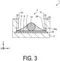
FIG. 3 is a cross-sectional view taken along line B-B illustrated inFIG. 2 . -
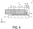
FIG. 4 is a cross-sectional view taken along line C-C illustrated inFIG. 2 . -
FIG. 5 is a horizontal cross-sectional view illustrating a heater according to a first variation of the embodiment. -
FIG. 6 is a horizontal cross-sectional view illustrating a heater according to a second variation of the embodiment. -
FIG. 7 is a vertical cross-sectional view illustrating a heater according to a third variation of the embodiment. -
FIG. 8 is a horizontal cross-sectional view illustrating a heater according to a fourth variation of the embodiment. -
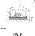
FIG. 9 is a horizontal cross-sectional view illustrating a heater according to a fifth variation of the embodiment. -
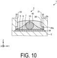
FIG. 10 is a horizontal cross-sectional view illustrating a heater according to a sixth variation of the embodiment. -
FIG. 11 is a plan view illustrating a heater according to a seventh variation of the embodiment. - An embodiment of a heater disclosed in the present application will be described below with reference to the accompanying drawings. The present disclosure is not limited by the following embodiment. Note that the drawings are schematic and that the dimensional relationships between elements, the proportions thereof, and the like may differ from the actual ones.
- First, a heater according to an embodiment is described with reference to
FIG. 1. FIG. 1 is a plan view of the heater according to the embodiment. - As illustrated in
FIG. 1 , aheater 1 according to the embodiment includes aceramic body 2, aheat generating resistor 4, aconductor 5, abonding material 7, and alead wire 10. Theheater 1 is used for, for example, a hair iron, a soldering iron, and other applications. - For the sake of clarity of description,
FIG. 1 illustrates a three-dimensional orthogonal coordinate system including the Z-axis that extends along a thickness direction of theheater 1. Such an orthogonal coordinate system may also be illustrated in other drawings used in the description below. - The
ceramic body 2 is, for example, a member having a flat plate shape. Theceramic body 2 is made of a material such as an insulating ceramic. Example materials of theceramic body 2 include an oxide ceramic, a nitride ceramic, a carbide ceramic, and the like. Specifically, an alumina ceramic, a silicon nitride ceramic, an aluminum nitride ceramic, a silicon carbide ceramic, or the like can be used as a material of theceramic body 2. - The
ceramic body 2 includes arecessed portion 3. Therecessed portion 3 is located in contact with anend surface 2a located at one end in the longitudinal direction of theceramic body 2. The recessedportion 3 is open on asurface 2b of the ceramic body 2 (seeFIG. 2 ). The details of the recessedportion 3 will be described later. - The heat generating
resistor 4 is located inside theceramic body 2. The heat generatingresistor 4 is a member that generates heat when electrical current flows therethrough. The heat generatingresistor 4 may include, for example, a high-resistance conductor containing tungsten, molybdenum, or the like. The shape of theheat generating resistor 4 is not limited to the illustrated shape, and may be appropriately changed in accordance with, for example, heat-generating characteristics required for theheater 1. - The
conductor 5 is electrically connected to theheat generating resistor 4. For example, theconductor 5 is located in contact with both ends of theheat generating resistor 4. Theconductor 5 is located overlapping therecessed portion 3 in a plan view. Theconductor 5 may be, for example, a metal material containing tungsten, molybdenum, or the like. Theconductor 5 may be made of the same material as or a different material from that of theheat generating resistor 4. - The bonding
material 7 is located inside therecessed portion 3. The bondingmaterial 7 bonds thelead wire 10 and theconductor 5. As thebonding material 7, a brazing material such as solder or silver solder can be used, for example. - The
lead wire 10 is a wire containing a metal material such as nickel, iron, or a nickel-based heat-resistant alloy. The cross section of thelead wire 10 may be, for example, circular, elliptical, or rectangular. The outer diameter of thelead wire 10, that is, the equivalent circle diameter of thelead wire 10 in a cross-sectional view may be, for example, from 0.5 to 2.0 mm. - The
heater 1 according to the embodiment is further described with reference toFIGs. 2 to 4 .FIG. 2 is an enlarged view of the region A illustrated inFIG. 1 .FIG. 3 is a cross-sectional view taken along line B-B illustrated inFIG. 2 .FIG. 4 is a cross-sectional view taken along line C-C illustrated inFIG. 2 . - As illustrated in
FIGs. 2 and4 , the recessedportion 3 includes abottom surface 34. An area of thebottom surface 34 is larger than an opening area of the opening end. Here, the opening area of the opening end refers to an area of a region surrounded by anend surface 2a of theceramic body 2 and ridge lines (opening end) 31 to 33 of the opening of the recessedportion 3 on asurface 2b of theceramic body 2, when viewed from a direction perpendicular to thesurface 2b of theceramic body 2, as illustrated inFIG. 2 . - Thus, the area of the
bottom surface 34 is made to be larger than the opening area of the opening end; whereby thelead wire 10 and theconductor 5 can be more firmly bonded via thebonding material 7. Since the opening area of the opening end is smaller than the area of thebottom surface 34, the proportion of thesurface 2b of theceramic body 2, which functions as a heating surface serving as a main part of theheater 1, increases and performance of the heater improves. - The
bottom surface 34 includes aperipheral edge portion 35. As illustrated inFIG. 2 , when viewed from a direction perpendicular to thesurface 2b of theceramic body 2, theperipheral edge portion 35 is located on the outer side of the opening end of the recessedportion 3. As illustrated inFIG. 3 , the recessedportion 3 includes atop surface 35a facing theperipheral edge portion 35. Thus, the recessedportion 3 includes a space sandwiched between thetop surface 35a and theperipheral edge portion 35. - The end portion of the
bonding material 7 is located at theperipheral edge portion 35 on the outer side of the opening end of the recessedportion 3 in a plan view. Thebonding material 7 extends from the center part of the recessedportion 3 so as to reach theperipheral edge portion 35; thus, thelead wire 10 can be more rigidly fixed. This reduces the possibility of occurrence of damage to thebonding material 7 and theceramic body 2 caused by, for example, the movement of thelead wire 10, thus reducing a decrease in the performance of theheater 1 over continuous use. - The
peripheral edge portion 35 may be provided on the entire wall surface or part of the wall surface of the recessedportion 3. For example, theperipheral edge portion 35 may be provided at a portion of the recessedportion 3 from which theconductor 5 is drawn out, while theperipheral edge portion 35 need not be provided at a portion of the recessedportion 3 from which theconductor 5 is not drawn out (for example, the rear end of the heater 1). Accordingly, the performance of the heater can be improved at the portion from which theconductor 5 is drawn out, while the possibility of generation of cracks, which starts from theperipheral edge portion 35 at the portion where theconductor 5 is not drawn out, can be reduced. As a result, heating efficiency can be improved, while increasing durability. - As illustrated in
FIG. 3 , the end portion of thebonding material 7 may include a portion located at theperipheral edge portion 35 on both sides in the Y-axis direction, which is a second direction intersecting the X-axis direction, which is a first direction in which thelead wire 10 extends, or may include a portion located at theperipheral edge portion 35 on either one side in the Y-axis direction. When the end portion of thebonding material 7 is partially located at theperipheral edge portion 35 on both sides in the Y-axis direction, a decrease in the performance of theheater 1 over continuous use can further be reduced. - Furthermore, as illustrated in
FIG. 4 , the end portion of thebonding material 7 may be in contact with aperipheral wall 36 that faces anend surface 10a of thelead wire 10 and is continuous with theperipheral edge portion 35 of the recessedportion 3. This reduces the possibility of occurrence of damage to thebonding material 7 and theceramic body 2 caused by, for example, the movement of thelead wire 10, thus reducing a decrease in the performance of theheater 1 over continuous use. In particular, when theheater 1 is used in a vibrating environment, the stress tends to concentrate on theend surface 10a in the longitudinal direction of thelead wire 10. In that case, by bringing thebonding material 7 into contact with theperipheral wall 36 of the recessedportion 3, which faces theend surface 10a of thelead wire 10, the stress concentration at the boundary between thebonding material 7 and theconductor 5 can be dispersed over theentire heater 1 via theperipheral wall 36. Thus, in theheater 1 with the end portion of thebonding material 7 being in contact with theperipheral wall 36, the stress can be relieved. - As illustrated in
FIGs. 3 and4 , the end portion of thebonding material 7 may be in contact with theperipheral wall 36 of the recessedportion 3 that extends in a direction intersecting thebottom surface 34. Since the end portion of thebonding material 7 is in contact with theperipheral wall 36, thebonding material 7 is surrounded by theceramic body 2 from above, below, and the sides at theperipheral wall 36; thus, a decrease in the performance of theheater 1 over continuous use can further be reduced. The end portion of thebonding material 7 may be in contact with theperipheral wall 36 over the entire circumference thereof, or thebonding material 7 may be in contact with part of theperipheral wall 36. In particular, since the end portion of thebonding material 7 is in contact with theperipheral wall 36 of the recessedportion 3 that faces theend surface 10a of thelead wire 10, the stress concentration occurs not at the boundary between thebonding material 7 and theconductor 5, but at the boundary between thebonding material 7 and theceramic body 2. Thus, the presence of the end portion of thebonding material 7 at theperipheral edge portion 35 reduces the possibility of occurrence of damage such as microcracks at the boundary between thebonding material 7 and theconductor 5, and thus reduces the possibility of a drop of electric resistance of theconductor 5 even after long-term use. - As illustrated in
FIGs. 3 and4 , theheater 1 may include aplating material 6 that covers the surface of theconductor 5. As theplating material 6, for example, a plating material containing nickel, chromium, or the like can be used. Disposing theplating material 6 between theconductor 5 and thebonding material 7, for example, can improve adhesion with thebonding material 7 and can further reduce a decrease in the performance of theheater 1 over continuous use. Thebonding material 7 may be directly located on thebottom surface 34 of the recessedportion 3 without theconductor 5 and theplating material 6 disposed thereon. When thebonding material 7 is located on thebottom surface 34, the possibility of, for example, separation of thebonding material 7. This can reduce a decrease in performance due to the separation of thebonding material 7. - The
plating material 6 may be located at theperipheral edge portion 35 together with theconductor 5. This further restricts the movement of, for example, thelead wire 10, and thus reduces the possibility of occurrence of damage to thebonding material 7 and theceramic body 2. Thus, a decrease in the performance of theheater 1 over continuous use can further be reduced. Theconductor 5 located at theperipheral edge portion 35 may be entirely covered with theplating material 6, or may be partially exposed from theplating material 6. - Variations of the embodiment will be described with reference to
FIGs. 5 to 11 . In the variations described below, the same components as those in the embodiment are denoted by the same reference numerals, and redundant description may be omitted. -
FIG. 5 is a horizontal cross-sectional view illustrating a heater according to a first variation of the embodiment. As illustrated inFIG. 5 , the end portion of thebonding material 7 may be located in contact with thetop surface 35a facing theperipheral edge portion 35 of the recessedportion 3. When the end portion of thebonding material 7 is in contact with thetop surface 35a, thebonding material 7 is sandwiched between thetop surface 35a and theperipheral edge portion 35 at theperipheral edge portion 35. Thus, the end portion of thebonding material 7 is sandwiched by theceramic body 2, so that the possibility of separation of thebonding material 7 is reduced. This can reduce a decrease in performance due to the separation of thebonding material 7. -
FIG. 6 is a horizontal cross-sectional view illustrating a heater according to a second variation of the embodiment. As illustrated inFIG. 6 , theheater 1 is different from theheater 1 illustrated inFIG. 5 in that a protrudingportion 35b protruding from thetop surface 35a toward thebottom surface 34 side is provided. In addition, the end portion of thebonding material 7 may be located so as to engage with the protrudingportion 35b. When the end portion of thebonding material 7 that is in contact with thetop surface 35a engages with the protrudingportion 35b, the possibility of, for example, separation of thebonding material 7 is reduced. This can further reduce a decrease in performance due to the separation of thebonding material 7. -
FIG. 7 is a vertical cross-sectional view illustrating a heater according to a third variation of the embodiment. As illustrated inFIG. 7 , theheater 1 differs from theheater 1 illustrated inFIG. 4 in that the end portion of thebonding material 7 is located away from theperipheral wall 36 facing theend surface 10a of thelead wire 10. - During assembly of the
heater 1, a twisting stress may be applied to the base portion of thelead wire 10 by, for example, bending thelead wire 10. In that case, for example, the end portion of thebonding material 7 is located at theperipheral edge portion 35 on both sides in the second direction intersecting the first direction in which thelead wire 10 extends, as illustrated inFIG. 3 . On the other hand, the end portion of thebonding material 7 is located away from theperipheral wall 36 of the recessedportion 3 that faces theend surface 10a of thelead wire 10, as illustrated inFIG. 7 . This allows withstanding of the twisting stress. Thus, in theheater 1 according to the present variation, a decrease in performance over continuous use can further be reduced. -
FIG. 8 is a horizontal cross-sectional view illustrating a heater according to a fourth variation of the embodiment. As illustrated inFIG. 8 , theheater 1 may include theceramic body 2 composed of a laminate of a plurality of ceramic materials. - The
ceramic body 2 of theheater 1 illustrated inFIG. 8 includes afirst member 21, a second member 22, and athird member 23. Thefirst member 21 and thethird member 23 may be, for example, plate-like members having a predetermined shape. The second member 22 located between thefirst member 21 and thethird member 23 may be, for example, a bonding material that bonds thefirst member 21 and thethird member 23. - When the second member 22 is not located between the
third member 23 and thefirst member 21, the surface of thefirst member 21 functions as thebottom surface 34. When the second member 22 is not provided between thefirst member 21 and thethird member 23, the surface of thethird member 23 functions as thetop surface 35a. The compositions of thefirst member 21, the second member 22, and thethird member 23 may be the same or different. The layered structure of theceramic body 2 is not limited to the one illustrated in the drawing. Theceramic body 2 may be, for example, a laminate of two materials or four or more materials. -
FIG. 9 is a horizontal cross-sectional view illustrating a heater according to a fifth variation of the embodiment. As illustrated inFIG. 9 , theheater 1 may further include anintermediate layer 8. Theheater 1 illustrated inFIG. 9 is different from theheater 1 illustrated inFIG. 4 in that theintermediate layer 8 is provided between theconductor 5 and theplating material 6. Theintermediate layer 8 contains at least one of metal elements contained in theconductor 5 and theplating material 6. Theintermediate layer 8 may be, for example, a mutual diffusion layer generated by a reaction between theconductor 5 and theplating material 6 during the firing of the heater material. - The
intermediate layer 8 may be located at theperipheral edge portion 35 together with theconductor 5 and theplating material 6. With theintermediate layer 8, theplating material 6 and theconductor 5 can be firmly bonded via theintermediate layer 8 at, for example, theperipheral edge portion 35. Even when a load is applied to thelead wire 10, for example, damage such as microcracks is less likely to occur at the end portion of thebonding material 7 and theconductor 5, where stress is likely to concentrate, and thus the electrical resistance of theconductor 5 is less likely to decrease even after long-term use. Thus, in theheater 1 according to the present variation, a decrease in performance over continuous use can further be reduced. -
FIG. 10 is a horizontal cross-sectional view illustrating a heater according to a sixth variation of the embodiment. As illustrated inFIG. 10 , theheater 1 may further include aresin material 40. Theresin material 40 may be made of, for example, a thermosetting resin, a photo-curable resin, or other curable resins. - The
resin material 40 is located inside the recessedportion 3 so as to cover thelead wire 10 and thebonding material 7. This further restricts the movement of, for example, thelead wire 10, and thus reduces the possibility of occurrence of damage to thebonding material 7 and theceramic body 2. Thus, a decrease in the performance of theheater 1 over continuous use can further be reduced. - In addition, the end portion of the
resin material 40 may be located at theperipheral edge portion 35 and may further face theperipheral wall 36. This further restricts the movement of, for example, thelead wire 10, decreasing the possibility of occurrence of damage to thebonding material 7 and theceramic body 2. Thus, a decrease in the performance of theheater 1 over continuous use can further be reduced. - The
heater 1 described in the above embodiment and variations includes the recessedportion 3 having a substantially rectangular shape in a plan view, but the shape of the recessedportion 3 is not limited thereto.FIG. 11 is a plan view illustrating a heater according to a seventh variation of the embodiment. - The recessed
portion 3 of theheater 1 illustrated inFIG. 11 includes afirst portion 37, asecond portion 38, and athird portion 39 in this order from theend surface 2a side of theceramic body 2. The dimensions in the Y-axis direction of thefirst portion 37 and thethird portion 39 are smaller than that of thesecond portion 38 located between thefirst portion 37 and thethird portion 39. The use of theceramic body 2 including such a recessedportion 3 improves the assembling accuracy of, for example, thelead wire 10. The shape of the recessedportion 3 is not limited to the illustrated shape. For example, the recessedportion 3 may include thefirst portion 37 and thesecond portion 38, or may include thesecond portion 38 and thethird portion 39. - Although the embodiment and variations of the present disclosure have been described above, the present disclosure is not limited to those described above, and various changes can be made without departing from the spirit thereof. For example, the
intermediate layer 8 illustrated inFIG. 9 and/or theresin material 40 illustrated inFIG. 10 may be applied to theheater 1 of other variations. Furthermore, other components of the above-described embodiment and variations can also be appropriately combined as long as no contradiction occurs. - As described above, the
heater 1 according to the embodiment includes theceramic body 2, theheat generating resistor 4, theconductor 5, and thebonding material 7. Theceramic body 2 includes the recessedportion 3 which is open on thesurface 2b. Theheat generating resistor 4 is located inside theceramic body 2. Theconductor 5 is electrically connected to theheat generating resistor 4 and is located on thebottom surface 34 of the recessedportion 3. Thebonding material 7 bonds theconductor 5 and thelead wire 10 located on theconductor 5. Thebottom surface 34 includes theperipheral edge portion 35 located on the outer side of the opening end of the recessedportion 3 in a plan view. The end portion of thebonding material 7 includes a portion located at theperipheral edge portion 35. This can reduce a decrease in performance over continuous use. - The
heater 1 according to the embodiment also includes theplating material 6 covering the surface of theconductor 5. Theconductor 5 and theplating material 6 are located at theperipheral edge portion 35. This can further reduce a decrease in performance over continuous use. - The
heater 1 according to the embodiment includes theintermediate layer 8 located between theconductor 5 and theplating material 6 and contains at least one of metal elements contained in theconductor 5 and theplating material 6. Theintermediate layer 8 is located at theperipheral edge portion 35. This can further reduce a decrease in performance over continuous use. - The end portion of the
bonding material 7 according to the embodiment is in contact with theperipheral wall 36 that is continuous with theperipheral edge portion 35. This can further reduce a decrease in performance over continuous use. - The end portion of the
bonding material 7 according to the embodiment is in contact with thetop surface 35a that is further continuous with theperipheral wall 36 continuous with theperipheral edge portion 35, and faces theperipheral edge portion 35. This can further reduce a decrease in performance over continuous use. - The end portion of the
bonding material 7 according to the embodiment is located at theperipheral edge portion 35 located in the second direction intersecting the first direction in which thelead wire 10 extends. This can reduce a decrease in performance over continuous use. - The end portion of the
bonding material 7 according to the embodiment is located at theperipheral edge portion 35 on both sides in the second direction intersecting the first direction in which thelead wire 10 extends. This can further reduce a decrease in performance over continuous use. - The end portion of the
bonding material 7 according to the embodiment is in contact with theperipheral wall 36 facing theend surface 10a of thelead wire 10 and being continuous with theperipheral edge portion 35. This can reduce a decrease in performance over continuous use. - The end portion of the
bonding material 7 according to the embodiment is located at theperipheral edge portion 35 on both sides in the second direction intersecting the first direction in which thelead wire 10 extends, and is located away from theperipheral wall 36 that faces theend surface 10a of thelead wire 10 and is continuous with theperipheral edge portion 35. This allows thelead wire 10 to withstand the twisting stress when it is applied to the base portion of thelead wire 10. This results in reduction of a decrease in performance over continuous use. - The
heater 1 according to the embodiment further includes theresin material 40 covering thelead wire 10 and thebonding material 7. The end portion of theresin material 40 is located at theperipheral edge portion 35. This can further reduce a decrease in performance over continuous use. - Additional effects and other aspects can be easily derived by a person skilled in the art. Thus, a wide variety of aspects of the present disclosure are not limited to the specific details and a representative embodiment represented and described above. Accordingly, various changes are possible without departing from the spirit or scope of the general inventive concepts defined by the appended claims and their equivalents.
-
- 1 Heater
- 2 Ceramic body
- 3 Recessed portion
- 4 Heat generating resistor
- 5 Conductor
- 6 Plating material
- 7 Bonding material
- 8 Intermediate layer
- 10 Lead wire
- 34 Bottom surface
- 35 Peripheral edge portion
- 36 Peripheral wall
- 40 Resin material
Claims (10)
- A heater comprising:a ceramic body comprising a recessed portion that is open on a surface of the ceramic body;a heat generating resistor located inside the ceramic body;a conductor electrically connected to the heat generating resistor and located on a bottom surface of the recessed portion; anda bonding material that bonds the conductor and a lead wire located on the conductor, whereinthe bottom surface comprises a peripheral edge portion located on an outer side of an opening end of the recessed portion in a plan view, andan end portion of the bonding material comprises a portion located at the peripheral edge portion.
- The heater according to claim 1, further comprising:a plating material covering a surface of the conductor, whereinthe conductor and the plating material are located at the peripheral edge portion.
- The heater according to claim 2, further comprising:an intermediate layer located between the conductor and the plating material and containing at least one of metal elements contained in the conductor and the plating material, whereinthe intermediate layer is located at the peripheral edge portion.
- The heater according to any one of claims 1 to 3, wherein
the end portion of the bonding material is in contact with a peripheral wall continuous with the peripheral edge portion. - The heater according to any one of claims 1 to 4, wherein
the end portion of the bonding material is in contact with a top surface that is further continuous with the peripheral wall continuous with the peripheral edge portion and faces the peripheral edge portion. - The heater according to any one of claims 1 to 5, wherein
the end portion of the bonding material is located at the peripheral edge portion in a second direction intersecting a first direction in which the lead wire extends. - The heater according to any one of claims 1 to 5, wherein
the end portion of the bonding material is located at the peripheral edge portion on both sides in a second direction intersecting a first direction in which the lead wire extends. - The heater according to claim 6 or 7, wherein
the end portion of the bonding material is in contact with the peripheral wall facing an end surface of the lead wire and being continuous with the peripheral edge portion. - The heater according to claim 7, wherein
the end portion of the bonding material is located away from the peripheral wall facing an end surface of the lead wire and being continuous with the peripheral edge portion. - The heater according to any one of claims 1 to 9, further comprising:a resin material covering the lead wire and the bonding material, whereinan end portion of the resin material is located at the peripheral edge portion.
Applications Claiming Priority (2)
| Application Number | Priority Date | Filing Date | Title |
|---|---|---|---|
| JP2021021220 | 2021-02-12 | ||
| PCT/JP2022/005469 WO2022173017A1 (en) | 2021-02-12 | 2022-02-10 | Heater |
Publications (2)
| Publication Number | Publication Date |
|---|---|
| EP4294119A1 true EP4294119A1 (en) | 2023-12-20 |
| EP4294119A4 EP4294119A4 (en) | 2025-02-05 |
Family
ID=82838340
Family Applications (1)
| Application Number | Title | Priority Date | Filing Date |
|---|---|---|---|
| EP22752839.5A Pending EP4294119A4 (en) | 2021-02-12 | 2022-02-10 | Heater |
Country Status (4)
| Country | Link |
|---|---|
| EP (1) | EP4294119A4 (en) |
| JP (2) | JP7615179B2 (en) |
| CN (1) | CN116830797A (en) |
| WO (1) | WO2022173017A1 (en) |
Families Citing this family (1)
| Publication number | Priority date | Publication date | Assignee | Title |
|---|---|---|---|---|
| WO2026029026A1 (en) * | 2024-08-01 | 2026-02-05 | 京セラ株式会社 | Ceramic structure |
Family Cites Families (17)
| Publication number | Priority date | Publication date | Assignee | Title |
|---|---|---|---|---|
| JPH04112476A (en) * | 1990-08-31 | 1992-04-14 | Noritz Corp | Ceramic heater |
| JP3228581B2 (en) * | 1992-12-24 | 2001-11-12 | 京セラ株式会社 | Ceramic heater |
| KR100280634B1 (en) * | 1996-05-05 | 2001-02-01 | 세이이치로 미야타 | Electric heating element and electrostatic chuck using the same |
| JP3266563B2 (en) * | 1998-01-30 | 2002-03-18 | 京セラ株式会社 | Aluminum nitride ceramic heater |
| JP2001257196A (en) * | 2000-03-09 | 2001-09-21 | Ibiden Co Ltd | Ceramic substrate for semiconductor manufacturing and checking device |
| CN1596557A (en) * | 2001-11-30 | 2005-03-16 | 揖斐电株式会社 | Ceramic heater |
| JPWO2005117493A1 (en) | 2004-05-27 | 2008-04-03 | 京セラ株式会社 | Ceramic heater, oxygen sensor and hair iron using the same |
| JP4641006B2 (en) * | 2005-06-16 | 2011-03-02 | 日本特殊陶業株式会社 | Ceramic joined body and ceramic heater |
| US7696455B2 (en) * | 2006-05-03 | 2010-04-13 | Watlow Electric Manufacturing Company | Power terminals for ceramic heater and method of making the same |
| US7763831B2 (en) * | 2006-12-15 | 2010-07-27 | Ngk Insulators, Ltd. | Heating device |
| JP5331490B2 (en) * | 2008-01-08 | 2013-10-30 | 日本碍子株式会社 | Junction structure and semiconductor manufacturing apparatus |
| JP6577362B2 (en) * | 2015-12-24 | 2019-09-18 | 京セラ株式会社 | heater |
| JP6829022B2 (en) * | 2016-07-27 | 2021-02-10 | 京セラ株式会社 | heater |
| JP6803396B2 (en) * | 2016-11-28 | 2020-12-23 | 京セラ株式会社 | heater |
| JP6838957B2 (en) * | 2016-12-19 | 2021-03-03 | 京セラ株式会社 | heater |
| KR102298654B1 (en) * | 2017-04-19 | 2021-09-07 | 주식회사 미코세라믹스 | Ceramic Heater with Improved Durability |
| JP7170745B2 (en) * | 2018-10-30 | 2022-11-14 | 京セラ株式会社 | Substrate-like structure and heater system |
-
2022
- 2022-02-10 JP JP2022580693A patent/JP7615179B2/en active Active
- 2022-02-10 WO PCT/JP2022/005469 patent/WO2022173017A1/en not_active Ceased
- 2022-02-10 EP EP22752839.5A patent/EP4294119A4/en active Pending
- 2022-02-10 CN CN202280013569.4A patent/CN116830797A/en active Pending
-
2024
- 2024-12-27 JP JP2024232617A patent/JP7760695B2/en active Active
Also Published As
| Publication number | Publication date |
|---|---|
| JPWO2022173017A1 (en) | 2022-08-18 |
| CN116830797A (en) | 2023-09-29 |
| WO2022173017A1 (en) | 2022-08-18 |
| JP7615179B2 (en) | 2025-01-16 |
| EP4294119A4 (en) | 2025-02-05 |
| JP7760695B2 (en) | 2025-10-27 |
| JP2025032020A (en) | 2025-03-07 |
Similar Documents
| Publication | Publication Date | Title |
|---|---|---|
| WO2018025571A1 (en) | Power semiconductor device | |
| EP2498289A2 (en) | IGBT power semiconductor package having an electrically conductive clip | |
| CN108934178B (en) | Sensor element and method for manufacturing sensor element | |
| EP4294119A1 (en) | Heater | |
| JP2014017483A (en) | Power semiconductor module having at least one conforming element reducing stress | |
| TWI277106B (en) | Thermistor having improved lead structure and secondary battery having the thermistor | |
| CN101207097A (en) | electrical terminal | |
| JP2016143804A (en) | Semiconductor device | |
| US20170351069A1 (en) | Electronic component mounting package and electronic device | |
| JP4702279B2 (en) | Semiconductor device and manufacturing method thereof | |
| JP5179869B2 (en) | Solar cells | |
| JP2004134746A (en) | Semiconductor device | |
| JPS6147668A (en) | Alternating load resistance switching operable semiconduttorelement | |
| KR20210130709A (en) | battery module | |
| TW200533270A (en) | Circuit board | |
| WO2021182047A1 (en) | Semiconductor device | |
| CN104283017B (en) | Electrical ground and constructional device for different metal part | |
| JP2019009280A (en) | Semiconductor device | |
| JP7285855B2 (en) | Ceramic structure and structure with terminals | |
| US12452961B2 (en) | Ceramic structure and wafer system | |
| JP6796666B2 (en) | Semiconductor device | |
| JP5885027B2 (en) | Thermistor element | |
| JP2006114716A (en) | Power semiconductor device | |
| JP7360992B2 (en) | Structure with terminal | |
| JP7285751B2 (en) | Heater and thermocompression bonding device equipped with the same |
Legal Events
| Date | Code | Title | Description |
|---|---|---|---|
| STAA | Information on the status of an ep patent application or granted ep patent |
Free format text: STATUS: THE INTERNATIONAL PUBLICATION HAS BEEN MADE |
|
| PUAI | Public reference made under article 153(3) epc to a published international application that has entered the european phase |
Free format text: ORIGINAL CODE: 0009012 |
|
| STAA | Information on the status of an ep patent application or granted ep patent |
Free format text: STATUS: REQUEST FOR EXAMINATION WAS MADE |
|
| 17P | Request for examination filed |
Effective date: 20230802 |
|
| AK | Designated contracting states |
Kind code of ref document: A1 Designated state(s): AL AT BE BG CH CY CZ DE DK EE ES FI FR GB GR HR HU IE IS IT LI LT LU LV MC MK MT NL NO PL PT RO RS SE SI SK SM TR |
|
| DAV | Request for validation of the european patent (deleted) | ||
| DAX | Request for extension of the european patent (deleted) | ||
| REG | Reference to a national code |
Ref country code: DE Ref legal event code: R079 Free format text: PREVIOUS MAIN CLASS: H05B0003020000 Ipc: H05B0003280000 |
|
| A4 | Supplementary search report drawn up and despatched |
Effective date: 20250109 |
|
| RIC1 | Information provided on ipc code assigned before grant |
Ipc: H05B 3/12 20060101ALI20250102BHEP Ipc: H05B 3/28 20060101AFI20250102BHEP |