EP4293984A1 - Datenübertragungssystem und -verfahren sowie zugehörige vorrichtung - Google Patents
Datenübertragungssystem und -verfahren sowie zugehörige vorrichtung Download PDFInfo
- Publication number
- EP4293984A1 EP4293984A1 EP22921439.0A EP22921439A EP4293984A1 EP 4293984 A1 EP4293984 A1 EP 4293984A1 EP 22921439 A EP22921439 A EP 22921439A EP 4293984 A1 EP4293984 A1 EP 4293984A1
- Authority
- EP
- European Patent Office
- Prior art keywords
- accelerator
- node
- data
- communication link
- accelerators
- Prior art date
- Legal status (The legal status is an assumption and is not a legal conclusion. Google has not performed a legal analysis and makes no representation as to the accuracy of the status listed.)
- Pending
Links
Images


Classifications
-
- H—ELECTRICITY
- H04—ELECTRIC COMMUNICATION TECHNIQUE
- H04L—TRANSMISSION OF DIGITAL INFORMATION, e.g. TELEGRAPHIC COMMUNICATION
- H04L47/00—Traffic control in data switching networks
- H04L47/10—Flow control; Congestion control
- H04L47/12—Avoiding congestion; Recovering from congestion
-
- H—ELECTRICITY
- H04—ELECTRIC COMMUNICATION TECHNIQUE
- H04L—TRANSMISSION OF DIGITAL INFORMATION, e.g. TELEGRAPHIC COMMUNICATION
- H04L47/00—Traffic control in data switching networks
- H04L47/10—Flow control; Congestion control
-
- H—ELECTRICITY
- H04—ELECTRIC COMMUNICATION TECHNIQUE
- H04L—TRANSMISSION OF DIGITAL INFORMATION, e.g. TELEGRAPHIC COMMUNICATION
- H04L47/00—Traffic control in data switching networks
- H04L47/10—Flow control; Congestion control
- H04L47/16—Flow control; Congestion control in connection oriented networks, e.g. frame relay
-
- G—PHYSICS
- G06—COMPUTING OR CALCULATING; COUNTING
- G06F—ELECTRIC DIGITAL DATA PROCESSING
- G06F15/00—Digital computers in general; Data processing equipment in general
- G06F15/16—Combinations of two or more digital computers each having at least an arithmetic unit, a program unit and a register, e.g. for a simultaneous processing of several programs
- G06F15/163—Interprocessor communication
-
- H—ELECTRICITY
- H04—ELECTRIC COMMUNICATION TECHNIQUE
- H04L—TRANSMISSION OF DIGITAL INFORMATION, e.g. TELEGRAPHIC COMMUNICATION
- H04L41/00—Arrangements for maintenance, administration or management of data switching networks, e.g. of packet switching networks
- H04L41/16—Arrangements for maintenance, administration or management of data switching networks, e.g. of packet switching networks using machine learning or artificial intelligence
-
- H—ELECTRICITY
- H04—ELECTRIC COMMUNICATION TECHNIQUE
- H04L—TRANSMISSION OF DIGITAL INFORMATION, e.g. TELEGRAPHIC COMMUNICATION
- H04L47/00—Traffic control in data switching networks
- H04L47/10—Flow control; Congestion control
- H04L47/12—Avoiding congestion; Recovering from congestion
- H04L47/125—Avoiding congestion; Recovering from congestion by balancing the load, e.g. traffic engineering
-
- H—ELECTRICITY
- H04—ELECTRIC COMMUNICATION TECHNIQUE
- H04L—TRANSMISSION OF DIGITAL INFORMATION, e.g. TELEGRAPHIC COMMUNICATION
- H04L47/00—Traffic control in data switching networks
- H04L47/10—Flow control; Congestion control
- H04L47/17—Interaction among intermediate nodes, e.g. hop by hop
Definitions
- This application relates to the field of computer technologies, and in particular, to a data transmission system and method, and a related device.
- This application discloses a data transmission system and method, and a related device, to reduce congestion and a transmission delay in a data transmission process, and improve data transmission efficiency.
- this application provides a data transmission system.
- the data transmission system includes a plurality of nodes, each of the plurality of nodes includes a plurality of accelerators, and the plurality of accelerators in each node are connected to each other through a first communication link.
- a plurality of communication planes are constructed between accelerators in the plurality of nodes, each communication plane includes one accelerator in each node, accelerators on any two communication planes are different from each other, and accelerators on a same communication plane are connected to each other through a second communication link.
- a first accelerator in a first node is configured to obtain first data sent by another accelerator in the first node.
- the first data includes data that needs to be sent by the another accelerator in the first node to a second accelerator in a second node.
- the first node and the second node are any two of the plurality of nodes.
- the first accelerator and the second accelerator are accelerators on a first communication plane.
- the first accelerator is further configured to send the first data to the second accelerator through the second communication
- the plurality of communication planes are constructed between the accelerators in the plurality of nodes, when one or more accelerators in the first node need to send data to accelerators on the first communication plane, the one or more accelerators first send, through a communication link in the first node, the data to the first accelerator that belongs to the first node and the first communication plane, and then the first accelerator separately sends the data to the accelerators on the first communication plane through the second communication link.
- the foregoing method can reduce a quantity of times that accelerators in nodes send data to each other, reduce data congestion and a transmission delay on a network, and improve data transmission efficiency.
- the another accelerator in the first node when the another accelerator in the first node needs to send data to a plurality of accelerators on the first communication plane, the another accelerator in the first node can first send, to the first accelerator, all data that needs to be sent to the accelerators on the first communication plane, and then the first accelerator sends the received data to each accelerator on the first communication plane through the second communication link.
- the other three accelerators in the first node send, to the first accelerator, all data that needs to be sent to the six accelerators on the first communication plane, and then the first accelerator sends, to each of the other five accelerators through the second communication link, data that is in the received data and that is required by each of the other five accelerators on the first communication plane.
- the plurality of communication planes are constructed between the accelerators in the plurality of nodes, when one or more accelerators in the first node need to send data to one or more accelerators on the first communication plane, the one or more accelerators first send, through a communication link in the first node, the data to the first accelerator that belongs to the first node and the first communication plane, and then the first accelerator sends data required by each accelerator on the first communication plane to each accelerator through the second communication link.
- the foregoing method can reduce a quantity of times that accelerators in nodes send data to each other, reduce data congestion and a transmission delay on a network, and improve data transmission efficiency.
- the data transmission system further includes a processor, and the processor is configured to send group information to each accelerator in the plurality of nodes.
- the group information includes information about an accelerator on each communication plane.
- the first accelerator is further configured to establish a connection of the second communication link to the second accelerator based on the received group information.
- the processor can group the accelerators based on the accelerators in each node, to determine information about the accelerators on each communication plane, and notify the accelerators in each node, so that the accelerators in each node establish connections based on the foregoing group information.
- the first accelerator is further configured to: when second data needs to be sent to any accelerator on a second communication plane, send the second data to a third accelerator in the first node.
- the third accelerator is an accelerator located on the second communication plane.
- the third accelerator is configured to send the second data to the any accelerator on the second communication plane through the second communication link.
- the first accelerator and the another accelerator in this node need to send data to one or more accelerators on the second communication plane
- the first accelerator and the another accelerator first send the data to the third accelerator
- the third accelerator sends data required by each accelerator on the second communication plane to each accelerator through the second communication link. This reduces an inter-node communication scale, reduces data congestion and a transmission delay on a network, and improves data transmission efficiency.
- the first accelerator is further configured to receive, through the second communication link, third data sent by each accelerator on the first communication plane.
- Data sent by one accelerator on the first communication plane to the first accelerator includes data that needs to be sent by a plurality of accelerators in a node in which the accelerator is located to the first accelerator.
- the data transmission system is used for artificial intelligence (artificial intelligence, AI) model training, and the first data, the second data, and the third data are intermediate data generated during AI model training.
- AI artificial intelligence
- the first communication link includes a peripheral component interconnect express (peripheral component interconnect express, PCIe) bus or a unified bus (unified bus, UB), and the second communication link is a link that supports the transmission control protocol (transmission control protocol, TCP), the remote direct memory access over converged Ethernet (remote direct memory access over converged Ethernet, RoCE) protocol, or the InfiniBand (InfiniBand, IB) protocol.
- PCIe peripheral component interconnect express
- UB unified bus
- TCP transmission control protocol
- RoCE remote direct memory access over converged Ethernet
- IB InfiniBand
- the plurality of nodes are deployed in one or more physical machines, and an accelerator in the plurality of nodes is a graphics processing unit (graphics processing unit, GPU), an embedded neural-network processing unit (neural-network processing unit, NPU), a tensor processing unit (tensor processing unit, TPU), or a deep learning processing unit (deep learning processing unit, DPU).
- graphics processing unit graphics processing unit, GPU
- NPU embedded neural-network processing unit
- NPU neural-network processing unit
- TPU tensor processing unit
- DPU deep learning processing unit
- this application provides a data transmission method.
- the method is applied to a data transmission system including a plurality of nodes, each of the plurality of nodes includes a plurality of accelerators, and the plurality of accelerators in each node are connected to each other through a first communication link.
- a plurality of communication planes are constructed between accelerators in the plurality of nodes, each communication plane includes one accelerator in each node, accelerators on any two communication planes are different from each other, and accelerators on a same communication plane are connected to each other through a second communication link.
- the data transmission method includes: A first accelerator in a first node obtains, through the first communication link, first data sent by another accelerator in the first node.
- the first data includes data that needs to be sent by the another accelerator in the first node to a second accelerator in a second node. Then, the first accelerator sends the first data to the second accelerator through the second communication link.
- the first node and the second node are any two of the plurality of nodes.
- the first accelerator and the second accelerator are accelerators on a first communication plane.
- the another accelerator in the first node when the another accelerator in the first node needs to send data to a plurality of accelerators on the first communication plane, the another accelerator in the first node can first send, to the first accelerator, all data that needs to be sent to the accelerators on the first communication plane, and then the first accelerator sends, to each accelerator on the first communication plane through the second communication link, data that is in the received data and that is required by each accelerator.
- the other three accelerators in the first node send, to the first accelerator, all data that needs to be sent to the six accelerators on the first communication plane, and then the first accelerator sends, to each of the other five accelerators through the second communication link, data that is in the received data and that is required by each of the other five accelerators on the first communication plane.
- the first accelerator receives group information sent by a processor, and establishes a connection of the second communication link to the second accelerator based on the group information.
- the group information includes information about an accelerator on each communication plane.
- the method further includes: When second data needs to be sent to any accelerator on a second communication plane, the first accelerator sends the second data to a third accelerator in the first node.
- the third accelerator is an accelerator located on the second communication plane. In this case, the third accelerator sends the second data to the any accelerator on the second communication plane through the second communication link.
- the first accelerator when the first accelerator needs to send data to a plurality of accelerators on the second communication plane, the first accelerator first sends the data to the third accelerator, and then the third accelerator sends data required by each accelerator on the second communication plane to each accelerator through the second communication link.
- the first accelerator is further configured to receive, through the second communication link, third data sent by each accelerator on the first communication plane.
- Data sent by one accelerator on the first communication plane to the first accelerator includes data that needs to be sent by a plurality of accelerators in a node in which the accelerator is located to the first accelerator.
- the data transmission system is used for AI model training, and the first data, the second data, and the third data are intermediate data generated during AI model training.
- AI model training a plurality of accelerators in a plurality of nodes need to be used to process data, a large amount of data needs to be transmitted between different accelerators, and intermediate data generated during artificial intelligence model training is transmitted by using the foregoing method. This can improve model training efficiency.
- the first communication link includes a PCIe bus or a UB
- the second communication link is a link that supports TCP, the RoCE protocol, or the IB protocol.
- the plurality of nodes are deployed in one or more physical machines, and an accelerator in the plurality of nodes is a GPU, an NPU, a TPU, or a DPU.
- this application provides a card, and the card includes a plurality of accelerators configured to perform the method according to any one of the second aspect and the possible implementations of the second aspect.
- this application provides a computing device, including a processor, a memory, and a plurality of accelerators.
- the memory stores computer instructions.
- the processor executes the computer instructions, the computing device invokes one or more accelerators to perform the method according to any one of the second aspect and the possible implementations of the second aspect.
- this application provides a computer-readable storage medium.
- the computer-readable storage medium stores a computer program.
- the accelerator executes the method according to any one of the second aspect and the possible implementations of the second aspect.
- “at least one” means one or more, and "a plurality of” means two or more.
- “and/or” describes an association relationship between associated objects, and represents that three relationships may exist.
- a and/or B may represent the following cases: Only A exists, both A and B exist, and only B exists, where A and B may be singular or plural.
- a character "/” generally indicates an "or” relationship between the associated objects. Any embodiment or design solution described by using “example” or “for example” in this application shall not be construed as being more preferred or more advantageous than another embodiment or design solution. Exactly, use of the word “example”, “for example”, or the like is intended to present a related concept in a specific manner.
- Artificial intelligence (artificial intelligence, AI) chip The AI chip is a module configured to process a large quantity of computing tasks in an artificial intelligence application.
- One computing device may have one or more AI chips.
- Network interface controller network interface controller, NIC: The NIC is also referred to as a network interface card.
- the NIC is computer hardware configured to support communication between computing devices on a network.
- An NIC of a computing device is configured to: connect the computing device to another computing device, or establish a connection between the computing device and a network device such as a switch.
- Peripheral component interconnect express switch peripheral component interconnect express switch, PCIe Switch
- the PCIe switch chip is a module configured to extend a PCIe link.
- the PCIe link uses an end-to-end connection manner, and each of two ends of one PCIe link can be connected to only one device or component. Therefore, the PCIe link may be extended by using the PCIe switch chip, so that one end of the PCIe link is connected to a plurality of devices or components.
- the PCIe switch chip is connected to another device or component through a PCIe bus.
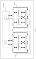
- FIG. 1 is a schematic diagram of a structure of a computing device according to an embodiment of this application.
- the computing device includes at least one central processing unit (central processing unit, CPU) and at least one node, and each node includes a plurality of accelerators.
- a host CPU Hex CPU
- the central processing unit is connected to the accelerators in each node through a bus or through a bus and a switch chip.
- one computing device includes two CPUs and two nodes, and each node includes four accelerators.
- One host CPU is separately connected to four accelerators in one node through a PCIe bus and a PCIe switch chip, and the four accelerators in the one node are connected through the PCIe bus.
- the computing device further includes components such as a memory and a network interface card that correspond to each accelerator.
- the foregoing accelerator may be any one of AI chips such as a graphics processing unit (graphics processing unit, GPU), an embedded neural-network processing unit (neural-network processing unit, NPU), a tensor processing unit (tensor processing unit, TPU), and a deep learning processing unit (deep learning processing unit, DPU).
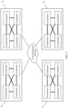
- FIG. 2 is a schematic diagram of a node cluster.
- Each node in the node cluster includes a plurality of accelerators, and different nodes are connected to each other through a communications network.
- the plurality of nodes in the node cluster may be nodes in one computing device shown in FIG. 1 , or may be nodes in different computing devices.
- quantities of nodes in the different computing devices may be the same or may be different.
- each accelerator generates data required by another accelerator. Therefore, the accelerator needs to send the data to the another accelerator that requires the data.
- the accelerator can send the data to the accelerators in the node through an internal high-speed link.
- each of a plurality of accelerators in one node generates data that needs to be sent to a target accelerator in another node
- each of the plurality of accelerators needs to send the data to the target accelerator in the another node through the communications network.
- each of four accelerators in a node N 0 generates data required by an accelerator 0 in a node N 2
- each of the four accelerators in the node N 0 needs to send the data to the accelerator 0 in the node N 2 through the communications network.
- a communication scale in the communications network is relatively large.
- each of the four accelerators in the node N 0 generates data required by four accelerators in a node N 1 and the four accelerators in the node N 2
- each of the four accelerators in the node N 1 also generates data required by the four accelerators in the node N 0 and the four accelerators in the node N 2 .
- the communication scale in the communications network is relatively large, network congestion is likely to be caused, and data transmission efficiency is reduced.
- the communication scale of the node cluster increases as a quantity of nodes increases, which is unfavorable to cluster expansion.
- An embodiment of this application provides a data transmission method.
- the method is applied to a data transmission system including a plurality of nodes in FIG. 3 , each of the plurality of nodes includes at least two accelerators, and the plurality of accelerators in each node are connected to each other through a first communication link.
- a plurality of communication planes are constructed between accelerators in the plurality of nodes, each communication plane includes one accelerator in each node, accelerators on any two communication planes are different from each other, and accelerators on a same communication plane are connected to each other through a second communication link.
- FIG. 3 shows a case in which accelerators (an accelerator 0 in each node) in only one communication plane are connected through the second communication link.
- the plurality of nodes may be nodes in one computing device, or may be nodes in a plurality of computing devices.
- a structure of the computing device is the computing device described in FIG. 1 .
- a plurality of accelerators in one node are connected through the first communication link, and can perform data exchange through the first communication link. Because accelerators in different nodes in one computing device are not connected to each other through the first communication link, the accelerators in the different nodes in the one computing device need to perform data exchange through the second communication link.
- accelerators in nodes in different computing devices are connected to each other through the second communication link.
- quantities of nodes included in any two computing devices may be the same or may be different.
- quantities of nodes included in any two computing devices may be the same or may be different.
- four accelerators in each node are connected through the first communication link. It should be understood that a quantity of accelerators that are connected through the first communication link in each node may alternatively be another quantity.
- the first communication link includes a bus, for example, a PCIe bus or a unified bus (unified bus, Ubus or UB).
- the first communication link may alternatively be a communications network including a bus and a switch chip, for example, a PCIe bus and a PCIe switch chip.
- the second communication link may be a link that supports TCP, the RoCE protocol, or the IB protocol, for example, an Ethernet or an IB network.
- Each accelerator corresponds to one network interface card, and accelerators in different nodes are connected through network devices such as a network interface card and a switch.
- the data transmission system includes n nodes N 0 to N n-1 , and each node includes m accelerators
- the data transmission system includes m*n accelerators in total, where both m and n are integers greater than 1.
- one accelerator in each node is connected to one accelerator in each of the other nodes through the second communication link, to form a communication plane connected through the second communication link.
- each communication plane includes one accelerator in one node, and accelerators on any two communication planes are different.
- the foregoing data transmission system including the n nodes that each include the m accelerators includes m communication planes in total, and each communication plane includes n accelerators.
- each accelerator In a process in which the foregoing n nodes jointly complete a task, for example, perform neural network model training in a model parallelism (model parallelism) manner, each accelerator generates data that needs to be sent to another accelerator.
- the one or more destination accelerators and the source accelerator may be located in a same node, or may be located in different nodes.
- some of the plurality of destination accelerators and the source accelerator may be located in a same node, and some destination accelerators and the source accelerator may be located in different nodes.
- data sent by the source accelerator to all destination accelerators may be the same, or data sent to some destination accelerators may be the same, or data sent to all accelerators may be different from each other. This is not specifically limited in this embodiment of this application.
- the accelerators in each node first perform data exchange through the first communication link.
- a first accelerator in a first node in the data transmission system is used as an example.
- the first node is any node in the data transmission system
- the first accelerator is any accelerator in the first node
- the first accelerator is located on a first communication plane of the data transmission system.
- the accelerator first sends, through the first communication link, the data to the first accelerator that is in the first node and that is located on the first communication plane.
- both the first accelerator and the another accelerator send the data to the accelerator that is in the first node and that is located on the second communication plane.
- the second communication plane is any communication plane in the data transmission system.
- Each accelerator in each node performs the foregoing intra-node data exchange operation. After each accelerator in each node completes the intra-node data exchange, each accelerator stores data required by each accelerator on a communication plane on which the accelerator is located. After each accelerator in each node completes the data exchange, the accelerators located on the same communication plane perform data exchange through the second communication link. Finally, each accelerator obtains data that needs to be sent by each accelerator in the data transmission system to the accelerator.
- the data sent by each accelerator includes indication information indicating a destination accelerator corresponding to the data, and the indication information may be an identifier or an address of the destination accelerator.
- the accelerator 1 in the node N 0 needs to send data to an accelerator 0 in the node N 1
- the accelerator 1 in the node N 0 sends the data to an accelerator 0 in the node N 0 .
- the data includes an address of the accelerator 0 in the node N 1 .
- numbers of m accelerators in the node 0 are respectively A 0 to A m-1
- numbers of m accelerators in the node 1 are respectively A m to A 2m-1
- numbers of m accelerators in the node N k are respectively A km to A (k+1)*m-1 , where k is an integer less than or equal to n.
- the accelerators A 0 , A m , A 2m , A km , ..., and A (n-1)m are accelerators located on a same communication plane
- the accelerators A 1 , A m+1 , A 2m+1 , ..., A km+1 , ..., and A (n-1)m+1 are accelerators located on a same communication plane.
- the accelerators A m-1 , A 2m-1 , A 3m-1 , ..., A (k+1)m-1 , ..., and A n*m-1 are accelerators located on a same communication plane.
- (x, y) is used to represent data that needs to be sent by an accelerator A x to an accelerator A y , where both x and y are integers greater than or equal to 0 and less than or equal to m*n.
- the data that needs to be sent by the accelerator to the other accelerators is (x, 0), (x, 1), (x, 2), ..., and (x, n*m-1).
- the accelerator first sends each piece of data to a forwarding accelerator corresponding to each piece of data.
- the forwarding accelerator is located in the node N k , and is located in an accelerator on a same communication plane as the destination accelerator.
- a x sends, to the accelerator A km , data to be sent to the destination accelerators A 0 , A m , A 2m , ..., A km , ..., and A (n-1)m , and sends, to the accelerator A km+1 , data that needs to be sent to the destination accelerators A 1 , A m+1 , A 2m+1 , ..., A km+1 , ..., and A (n-1)m+1 .
- a x sends, to the accelerator A (k+1)*m-1 , data that needs to be sent to the destination accelerators A m-1 , A 2m-1 , A 3m-1 , ..., A (k+1)m-1 , ..., and A n*m-1 .
- the accelerator A x receives data sent by another accelerator in the node N k , and the data received by the accelerator A x is data that needs to be sent to an accelerator that is located on a same communication plane as A x .
- any accelerator in the node N k performs the foregoing operations.
- data obtained by the any accelerator in the node N k is data required by n accelerators that are located on a same communication plane as the accelerator.
- the accelerator A km needs to send data to A 0 , A m , A 2m , ..., A km , ..., and A (n-1)m
- the accelerator A km+1 needs to send data to A 1 , A m+1 , A 2m+1 , ..., A km+1 , ..., and A (n-1)m+1 .
- an accelerator in any node in the data transmission system performs the foregoing operations.
- any accelerator obtains data required by n accelerators that are located on a same communication plane as the accelerator.
- the accelerator A 0 needs to send data to A 0 , A m , A 2m , ..., A km , ..., and A (n-1)m
- the accelerator A 1 needs to send data to A 1 , A m+1 , A 2m+1 , ..., A km+1 , ..., and A (n-1)m+1 .
- each accelerator performs inter-node data exchange.
- each accelerator sends, to each accelerator that is located on a same communication plane as the accelerator, data required by the accelerator, to complete data exchange between the accelerators on the same communication plane.
- each accelerator obtains data that needs to be sent by each accelerator in the data transmission system to the accelerator.
- the accelerator A 0 sends, to A m through the second communication link, data that needs to be sent to A m
- the accelerator A 0 sends, to A km through the second communication link, data that needs to be sent to A km .
- the accelerator A 0 obtains data that needs to be sent by each accelerator to A 0
- a km obtains data that needs to be sent by each accelerator to A km .
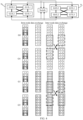
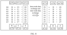
- FIG. 4 is a schematic diagram of data transmission according to an embodiment of this application.
- FIG. 4 shows only a connection relationship between GPUs in a node and a connection relationship between GPUs on one communication plane.
- N 0 includes four GPUs in total: G0, G1, G2, and G3, and
- N 1 includes four GPUs in total: G4, G5, G6, and G7.
- the data transmission system includes four communication planes in total: L0, L1, L2, and L3.
- the communication plane L0 includes G0 and G4, the communication plane L1 includes G1 and G5, the communication plane L2 includes G2 and G6, and the communication plane L3 includes G3 and G7.
- Each GPU needs to send data to all the GPUs in the two nodes. For example, G0 needs to send data (0, 0), (0, 1), ..., and (0, 7) to G0 to G7, and G1 needs to send data (1, 0), (1, 1), ..., and (1, 7) to G0 to G7.
- G7 needs to send data (7, 0), (7, 1), ..., and (7, 7) to G0 to G7.
- That N 0 and N 1 first separately perform data exchange between the GPUs in each node specifically includes: For any GPU in N 0 or N 1 , for example, G0 in N 0 , when one or more GPUs in N 0 need to send data to a GPU that is located on the communication plane L0, the one or more GPUs first send the data to G0 through the first communication link. When G0 needs to send data to a destination GPU on another communication plane, G0 first sends, through the first communication link, the data to a GPU that is in N 0 and that is located on a same communication plane as the destination GPU.
- G0 receives the data (1, 0) and (1, 4) sent by G1, receives the data (2, 0) and (2, 4) sent by G2, and receives the data (3, 0) and (3, 4) sent by G3.
- G0 sends, to G1, both the data (0, 1) that needs to be sent to G1 and the data (0, 5) that needs to be sent to G5;
- G0 sends, to G2, both the data (0, 2) that needs to be sent to G2 and the data (0, 6) that needs to be sent to G6;
- G0 sends, to G3, both the data (0, 3) that needs to be sent to G3 and the data (0, 7) that needs to be sent to G7.
- Each GPU in N 0 and N 1 performs intra-node data exchange. After each GPU in each node completes the intra-node data exchange, data in the GPU is data required by each GPU that is located on a same communication plane as the GPU. As shown in FIG.
- data in G0 is data required by G0 and G4, and includes the data (0, 0), (1, 0), (2, 0), (3, 0), (0, 4), (1, 4), (2, 4), and (3, 4);
- data in G1 is data required by G1 and G5, and includes the data (0, 1), (1, 1), (2, 1), (3, 1), (0, 5), (1, 5), (2, 5), and (3, 5);
- data in G4 is data required by G0 and G4, and includes the data (4, 0), (5, 0), (6, 0), (7, 0), (4, 4), (5, 4), (6, 4), and (7, 4);
- data in G5 is data required by G1 and G5, and includes data (4, 1), (5, 1), (6, 1), (7, 1), (4, 5), (5, 5), (6, 5), and (7, 5).
- GPUs that are located on a same communication plane perform inter-node data exchange through the second communication link, and each GPU sends data required by each of the other GPUs on the same communication plane to the corresponding GPU through the second communication link.
- G0 sends the data (0, 4), (1, 4), (2, 4), and (3, 4) to G4
- G4 sends the data (4, 0), (5, 0), (6, 0), and (7, 0) to G0
- G1 sends the data (0, 5), (1, 5), (2, 5), and (3, 5) to G5
- G5 sends the data (4, 1), (5, 1), (6, 1), and (7, 1) to G1.
- Data interaction of another communication plane is the same as the data interaction described above, and details are not described herein again.
- data in each GPU is data that needs to be sent by each GPU in the data transmission system to the GPU.
- the data in G0 is (0, 0), (1, 0), (2, 0), (3, 0), (4, 0), (5, 0), (6, 0), and (7, 0)
- the data in G5 is (0, 5), (1, 5), (2, 5), (3, 5), (4, 5), (5, 5), (6, 5), and (7, 5).
- FIG. 5 is a schematic diagram of another data transmission according to an embodiment of this application.
- the data transmission system includes four computing devices, each computing device includes two nodes, and each node includes four GPUs. In other words, the data transmission system includes 32 GPUs in total: G0 to G31.
- the data transmission system includes four communication planes in total. As shown in FIG.
- the four communication planes are respectively L0, L1, L2, and L3.
- the communication plane L0 includes G0, G4, G8, G12, G16, G20, G24, and G28.
- the communication plane L1 includes G1, G5, G9, G13, G17, G21, G25, and G29.
- the communication plane L2 includes G2, G6, G10, G14, G18, G22, G26, and G30.
- the communication plane L3 includes G3, G7, G11, G15, G19, G23, G27, and G31.
- Each communication plane includes eight GPUs.
- FIG. 5 shows only a case in which the communication plane L0 is connected through the second communication link.
- each GPU in the data transmission system needs to send data to another GPU
- data exchange is first performed between GPUs in a node.
- G0 receives data sent by G1 to G3 in the node N 0 to each GPU on the communication plane L0.
- G0 sends, to G1, data that needs to be sent to each GPU on the communication plane L1;
- G0 sends, to G2, data that needs to be sent to each GPU on the communication plane L2;
- G0 sends, to G3, data that needs to be sent to each GPU on the communication plane L3.
- Data exchange can also be performed between GPUs in another node according to the foregoing method.
- G21 in the node N 5 receives data separately sent by G20, G22, and G23 to each GPU on the communication plane L1.
- G21 sends, to G20, data that needs to be sent to each GPU on the communication plane L0;
- G21 sends, to G22, data that needs to be sent to each GPU on the communication plane L2;
- G21 sends, to G23, data that needs to be sent to each GPU on the communication plane L3.
- data in the GPU is data required by each GPU that is located on a same communication plane as the GPU.
- data in G0 is data required by each of the eight GPUs on the communication plane L0
- data in G1 is data required by each of the eight GPUs on the communication plane L1
- data in G4 is data required by each of the eight GPUs on the communication plane L0
- data in G6 is data required by each of the eight GPUs on the communication plane L2.
- GPUs that are located on a same communication plane perform inter-node data exchange through the second communication link.
- Each GPU sends data required by another GPU on the same communication plane to the another GPU through the second communication link.
- G0 sends the data (0, 4), (1, 4), (2, 4), and (3, 4) to G4, sends the data (0, 8), (1, 8), (2, 8), and (3, 8) to G8, and sends the data (0, 12), (1, 12), (2, 12), and (3, 12) to G12, and so on.
- G4 sends the data (4, 0), (5, 0), (6, 0), and (7, 0) to G0, sends the data (4, 8), (5, 8), (6, 8), and (7, 8) to G8, and sends the data (4, 12), (5, 12), (6, 12), and (7, 12) to G12, and so on.
- G1 sends the data (0, 5), (1, 5), (2, 5), and (3, 5) to G5;
- G5 sends the data (4, 1), (5, 1), (6, 1), and (7, 1) to G1; and the like.
- Data interaction between GPUs on another communication plane is the same as the data interaction described above, and details are not described herein again.
- data in each GPU is data that needs to be sent by each GPU in the data transmission system to the GPU.
- the data in G0 is (0, 0), (1, 0), (2, 0), ..., and (31, 0)
- the data in G1 is (0, 1), (1, 1), (2, 1), ..., and (31, 1).
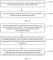
- FIG. 6 is a schematic flowchart of a data transmission method according to an embodiment of this application.
- the data transmission method is applied to the data transmission system shown in FIG. 3 .
- the data transmission method includes S601 and S602.
- a first accelerator obtains first data sent by another accelerator in a first node through a first communication link.
- the first data includes data that needs to be sent by another accelerator in the first node to a second accelerator in a second node.
- the first node and the second node are any two of a plurality of nodes in the data transmission system.
- the first accelerator and the second accelerator are accelerators on a first communication plane.
- each accelerator In a process in which the foregoing n nodes jointly complete a task, for example, perform neural network model training in a model parallelism (model parallelism) manner, each accelerator generates data that needs to be sent to another accelerator.
- One or more accelerators in the first node generate data that needs to be sent to the second accelerator in the second node.
- the one or more accelerators in the first node send, to the first accelerator that is located on a same communication plane as the second accelerator, the data that needs to be sent by each accelerator to the second accelerator.
- the data sent by each accelerator includes indication information for sending the data to the second accelerator, for example, an identifier of the second accelerator or an address of the second accelerator.
- the first node and the second node may be two nodes in a same computing device, or may be two nodes in different computing devices.
- the first accelerator sends the first data to the second accelerator through a second communication link.
- the first accelerator After receiving the data that is sent by each accelerator in the first node and that needs to be sent to the second accelerator, the first accelerator obtains the first data, and then sends the first data to the second accelerator through the second communication link.
- the first node may be N 0 in FIG. 4
- the second node is N 1 in FIG. 4
- the first accelerator is G0 in FIG. 4
- the second accelerator is G4 in FIG. 4 .
- a specific data exchange operation is not described herein again.
- FIG. 6 is a schematic flowchart of another data transmission method according to an embodiment of this application.
- the data transmission method is applied to the data transmission system shown in FIG. 3 .
- the data transmission method includes S701 to S703.
- a processor sends group information to each accelerator in a node managed by the processor, where the group information includes information about an accelerator on each communication plane.
- the foregoing data transmission system includes n nodes and at least one host CPU.
- Each node includes m accelerators, and one host CPU manages at least one node.
- the group information includes the information about the accelerator on each communication plane in the data transmission system.
- the information about the accelerator may be an identifier or an address of the accelerator.
- the data transmission system shown in FIG. 5 includes eight nodes, each node includes four GPUs, the data transmission system includes four communication planes, and each communication plane includes eight GPUs.
- the group information includes information about the eight GPUs on each communication plane.
- the accelerator in each node establishes, based on the foregoing group information, a connection of the second communication link to each of other accelerators that are located on a same communication plane.
- S702 The accelerator in each node performs intra-node data exchange, so that data obtained by one accelerator is data required by each accelerator that is located on a same communication plane as the accelerator.
- each accelerator In a process in which the foregoing n nodes jointly complete a task, for example, perform neural network model training in a model parallelism manner, each accelerator generates data that needs to be sent to another accelerator.
- one or more accelerators in the first node generate first data that needs to be sent to the second accelerator in the second node.
- the one or more accelerators in the first node determine, based on the foregoing group information, that the first accelerator in the first node and the second accelerator in the second node are located on a same communication plane.
- the one or more accelerators in the first node first send, to the first accelerator through the first communication link, the data that needs to be sent by each accelerator to the second accelerator.
- the data sent by each accelerator in the first node includes indication information for sending the data to the second accelerator, for example, an identifier of the second accelerator or an address of the second accelerator.
- the first node and the second node are any two different nodes in the data transmission system.
- the first node and the second node may be two nodes in a same computing device, or may be two nodes in different computing devices.
- the another accelerator in the first node when the another accelerator in the first node needs to send data to a plurality of accelerators on the first communication plane, the another accelerator in the first node can first send, to the first accelerator, data that needs to be sent to each accelerator on the first communication plane.
- the first node includes four accelerators
- the first communication plane includes six accelerators
- each of the other three accelerators in the first node sends, to the first accelerator, data that needs to be sent to the six accelerators on the first communication plane.
- the first accelerator in the first node generates second data that needs to be sent to a fourth accelerator in the second node, and the first accelerator determines, based on the foregoing group information, that a third accelerator in the first node and the fourth accelerator are located on a same communication plane.
- the first accelerator sends the second data to the third accelerator, so that the third accelerator sends the second data to the fourth accelerator through the second communication link.
- the second data includes indication information for sending the second data to the fourth accelerator.
- the accelerator in each node after the accelerator in each node generates the data that needs to be sent to the another accelerator, the accelerator in each node performs data exchange between accelerators in the node through the first communication link. Finally, data obtained by one accelerator is data required by each accelerator that is located on a same communication plane as the accelerator.
- a method for performing data exchange between accelerators in a node refer to the operations related to intra-node data exchange in embodiments corresponding to FIG. 3 to FIG. 5 . Details are not described herein again.
- Each of the accelerators on the same communication plane performs inter-node data exchange through the second communication link, to obtain data required by each accelerator.
- the first accelerator After receiving the data that is sent by each of the other accelerators in the first node and that needs to be sent to the second accelerator, the first accelerator sends, to the second accelerator through the second communication link according to the indication information in the received data, the data that needs to be sent by each of the other accelerators to the second accelerator and the data that needs to be sent by the first accelerator to the second accelerator.
- the third accelerator sends the second data to the fourth accelerator through the second communication link.
- the first accelerator also receives, through the second communication link, third data sent by each of the other accelerators on the first communication plane.
- the third data includes data sent by an accelerator in a node to which each accelerator on the first communication plane belongs to the first accelerator.
- a memory of any accelerator stores data required by each accelerator on a communication plane on which the accelerator is located. Then, the accelerators located on the same communication plane perform inter-node data exchange through the second communication link. Finally, each accelerator obtains data required by each accelerator, that is, data that needs to be sent by each accelerator in the data transmission system to the accelerator.
- accelerators in each node when accelerators in a plurality of nodes need to perform data exchange with each other, accelerators in each node first perform data exchange through a communication link in the node. After the accelerators in each node perform data exchange through first communication link in the node, data in any accelerator is data required by each accelerator that is located on a same communication plane as the accelerator, and the accelerators located on the same communication plane perform data exchange through the second communication link. Finally, each accelerator obtains data required by each accelerator.
- an internal high-speed link in a node can be fully used to implement data aggregation on a same communication plane, and then data exchange is performed between accelerators in nodes through the second communication link.
- G1 to G3 first send, to G0 through the first communication link in the node, the data that needs to be sent to G4, then G0 sends, to G4 through the second communication link, the data that needs to be sent by G0 to G3 to G4, and G0 to G3 do not need to separately send the data to G4 through the second communication link.
- FIG. 8 is a schematic diagram of a matrix operation according to an embodiment of this application.
- FIG. 8 is a schematic diagram of performing model training by using the data transmission system including two nodes and eight GPUs in FIG. 4 .
- B is a matrix of a*b
- C is a matrix of b*c
- D is a matrix of c*d
- E B x C.
- E B x C.
- E is a matrix of a*c.
- the matrix C has a relatively large amount of data.
- the matrix C is an embedding table (embedding table).
- the matrix C needs to be deployed in a plurality of GPUs, for example, deployed in eight GPUs in total: G0 to G7.
- input data of the eight GPUs is the matrix B and one submatrix of the matrix C, that is, each GPU completes partial computation of matrix multiplication B*C.
- each GPU needs to continue to cooperate to complete a matrix multiplication operation with the matrix D.
- the matrix D is a matrix of c*d
- the matrices E0 to E7 cannot directly perform matrix multiplication computation with the matrix D
- the matrix in each GPU needs to be first converted into a matrix with c columns by using the foregoing method for performing data exchange between GPUs in each node and data exchange between GPUs in nodes on a same communication plane.
- a matrix E obtained by combining the matrices E0 to E7 is a matrix of a*c.
- the matrix E0 in G0 is equivalent to columns 1 to 100 in the matrix E
- the matrix E1 in G1 is equivalent to columns 101 to 200 in the matrix E
- the matrix E2 in G2 is equivalent to columns 201 to 300 in the matrix E.
- the matrix E7 in G7 is equivalent to columns 701 to 800 in the matrix E.
- the matrix in each GPU is first divided into eight 25*100 matrices by row. If the matrix F0 finally obtained in G0 is data of rows 1 to 25 in the matrix E, G0 needs to receive data of rows 1 to 25 in each matrix in G1 to G7.
- G1 needs to receive data of rows 26 to 50 in each matrix in G0 and G2 to G7.
- the matrix F2 finally obtained in G2 is data of rows 51 to 75 in the matrix E, G2 needs to receive data of rows 51 to 75 in each matrix in G0, G1, and G3 to G7.
- the matrix F7 finally obtained in G7 is data of rows 176 to 200 in the matrix E, G7 needs to receive data of rows 176 to 200 in each matrix in G0 to G6.
- data of rows 1 to 25 in G0 is data required by G0, and is data sent by G0 to G0, which is equivalent to the data (0, 0) in the embodiment corresponding to FIG. 4 .
- Data of rows 26 to 50 in G0 is data required by G1, and is data sent by G0 to G1, which is equivalent to the data (0, 1) in the embodiment corresponding to FIG. 4 .
- data of rows 176 to 200 in G0 is data required by G7, and is data sent by G0 to G7, which is equivalent to the data (0, 7) in the embodiment corresponding to FIG. 4 . Therefore, G0 includes the data (0, 0), (0, 1), ..., and (0, 7) sent to G0 to G7.
- data of rows 1 to 25 in G1 is data required by G0, and is data sent by G1 to G0, which is equivalent to the data (1, 0) in the embodiment corresponding to FIG. 4 .
- Data of rows 26 to 50 in G1 is data required by G1, and is data sent by G1 to G1, which is equivalent to the data (1, 1) in the embodiment corresponding to FIG. 4 .
- data of rows 176 to 200 in G1 is data required by G7, and is data sent by G1 to G7, which is equivalent to the data (1, 7) in the embodiment corresponding to FIG. 4 . Therefore, G1 includes the data (1, 0), (1, 1), ..., and (1, 7) sent to G0 to G7.
- G2 includes the data (2, 0), (2, 1), ..., and (2, 7) sent to G0 to G7;
- G3 includes the data (3, 0), (3, 1), ..., and (3, 7) sent to G0 to G7;
- G4 includes the data (4, 0), (4, 1), ..., and (4, 7) sent to G0 to G7;
- G5 includes the data (5, 0), (5, 1), ..., and (5, 7) sent to G0 to G7;
- G6 includes the data (6, 0), (6, 1), ..., and (6, 7) sent to G0 to G7; and
- G7 includes the data (7, 0), (7, 1), ..., and (7, 7) sent to G0 to G7.
- Data that needs to be sent by one GPU to another GPU is data of 25 rows and 100 columns.
- any GPU in G0 to G7 needs to send data of 25 rows and 100 columns to each GPU, and each GPU also needs to receive the data of 25 rows and 100 columns sent by each of the other GPUs, so that E0 in G0 can be converted into F0, E1 in G1 can be converted into F1, and so on.
- data in each of the eight GPUs is converted into each of matrices F0 to F7 of a1*c through data exchange between GPUs in a node and data exchange between GPUs in nodes on a same communication plane, and the matrix in each GPU completes the matrix multiplication operation with the matrix D, to obtain matrices Z0 to Z7 of a1*d.
- FIG. 10 is a schematic diagram of a structure of a data transmission apparatus according to an embodiment of this application.
- the data transmission apparatus 100 is used for any accelerator in the foregoing data transmission system.
- the data transmission apparatus 100 includes a communications unit 101 and a processing unit 102.
- the communications unit 101 is configured to obtain, through a first communication link, first data sent by another accelerator in a first node.
- the first data includes data that needs to be sent by the another accelerator in the first node to a second accelerator in a second node.
- the first node and the second node are any two of a plurality of nodes.
- the first accelerator and the second accelerator are accelerators on a first communication plane. For example, one or more accelerators in the first node generate first data that needs to be sent to the second accelerator in the second node.
- the one or more accelerators in the first node determine that the first accelerator in the first node and the second accelerator in the second node are located on a same communication plane.
- the one or more accelerators in the first node first send, to the first accelerator through the first communication link, the data that needs to be sent by each accelerator to the second accelerator.
- the data sent by the one or more accelerators in the first node includes indication information for sending the data to the second accelerator, for example, an identifier of the second accelerator or an address of the second accelerator.
- the processing unit 102 is configured to: after the communications unit 101 of the first accelerator receives the data sent by the another accelerator in the first node, determine, based on the indication information in the data sent by each accelerator, a destination accelerator of the data sent by each accelerator, that is, the second accelerator, and then send, to the second accelerator by using the communications unit 101, the data to be sent by each accelerator to the second accelerator.
- the processing unit 102 is further configured to: determine second data that needs to be sent to a fourth accelerator, and determine that a third accelerator in the first node and the fourth accelerator are located on a same communication plane; and the communications unit 101 is further configured to send the second data to the third accelerator in the first node through the first communication link, so that the third accelerator sends the second data to the fourth accelerator through a second communication link.
- the fourth accelerator is an accelerator located in a different node from the first accelerator, and the second data includes indication information for sending the second data to the fourth accelerator.
- the communications unit 101 is further configured to receive data sent by another accelerator that is located on a same communication plane as the first accelerator.
- FIG. 11 is a schematic diagram of a structure of a card according to an embodiment of this application.
- the card 110 includes a plurality of accelerators 111 and a plurality of network interface controllers (network interface controller, NIC) 112. Some or all of the plurality of accelerators 111 are connected through a first communication link.
- the card 110 includes one or more nodes described in embodiments corresponding to FIG. 3 to FIG. 5 .
- a plurality of accelerators in each node are connected to each other through the first communication link, each accelerator 111 is connected to one NIC 112 through a bus 113, and one NIC 112 can be used by one or more accelerators 111 to send or receive data.
- the NIC 112 corresponding to each accelerator 111 is configured to send data to an accelerator 111 in another node, or receive data sent by an accelerator 111 in another node.
- the accelerator 111 may be any one of AI chips such as a GPU, an NPU, a TPU, and a DPU.
- the card 110 can be disposed in a computing device, and an accelerator 111 connected to the card 110 through the first communication link can complete all operations of intra-node data exchange described in embodiments corresponding to FIG. 3 to FIG. 9 ; and can also construct the second communication link in the foregoing method embodiments with a node on another card 110 in the computing device, so that accelerators 111 in a plurality of nodes on a plurality of cards 110 can complete all operations of inter-node data exchange described in embodiments corresponding to FIG. 3 to FIG. 9 .
- the plurality of nodes on the card 110 can establish the second communication link described in the foregoing method embodiments, and an accelerator 111 connected to any node on the card 110 through the first communication link can complete all operations of intra-node data exchange described in embodiments corresponding to FIG. 3 to FIG. 9 ; and can also cooperate with an accelerator in another node on the card 110 to complete all operations of inter-node data exchange described in embodiments corresponding to FIG. 3 to FIG. 9 , or cooperate with an accelerator in another node on another card 110 in the computing device to complete all operations of inter-node data exchange described in embodiments corresponding to FIG. 3 to FIG. 9 .
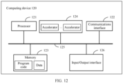
- FIG. 12 is a schematic diagram of a computing device according to an embodiment of this application.
- the computing device 120 includes one or more processors 121, a communications interface 122, a memory 123, and a plurality of accelerators 124.
- the processor 121, the communications interface 122, the memory 123, and the accelerator 124 are connected to each other through a bus 125.
- a plurality of accelerators 124 can construct one or more nodes described in FIG. 3 , and the plurality of accelerators 124 may be deployed on one or more cards 110 shown in FIG. 11 .
- processor 121 For various operations performed by the processor 121, refer to the specific operations in S701 in FIG. 7 .
- For a specific operation performed by any accelerator 124 refer to the operation performed by the accelerator in embodiments described in FIG. 3 to FIG. 9 .
- For a relationship between the processor 121 and the accelerator 124 refer to related descriptions in FIG. 3 . Details are not described herein again.
- the processor 121 may have a plurality of specific implementation forms.
- the processor 121 may be a CPU, and the processor 121 may be a single-core processor or a multicore processor.
- the processor 121 may be a combination of a CPU and a hardware chip.
- the hardware chip may be an application-specific integrated circuit (application-specific integrated circuit, ASIC), a programmable logic device (programmable logic device, PLD), or a combination thereof.
- the PLD may be a complex programmable logic device (complex programmable logic device, CPLD), a field programmable logic gate array (field programmable gate array, FPGA), generic array logic (generic array logic, GAL), or any combination thereof.
- the processor 121 may alternatively be implemented independently by using a logic device with built-in processing logic, for example, an FPGA or a digital signal processor (digital signal processor, DSP).
- the accelerator 124 may be any one of AI chips such as a GPU, an NPU, a TPU, and a DPU.
- the communications interface 122 may be a wired interface or a wireless interface, and is configured to communicate with another module or device.
- the wired interface may be an Ethernet interface or a local interconnect network (local interconnect network, LIN).
- the wireless interface may be a cellular network interface, a wireless local area network interface, or the like.
- the memory 123 may be a nonvolatile memory, for example, a read-only memory (read-only memory, ROM), a programmable read-only memory (programmable ROM, PROM), an erasable programmable read-only memory (erasable PROM, EPROM), an electrically erasable programmable read-only memory (electrically EPROM, EEPROM), or a flash memory.
- the memory 123 may alternatively be a volatile memory.
- the volatile memory may be a random access memory (random access memory, RAM), and is used as an external cache.
- RAMs may be used, for example, a static random access memory (static RAM, SRAM), a dynamic random access memory (dynamic RAM, DRAM), a synchronous dynamic random access memory (synchronous DRAM, SDRAM), a double data rate synchronous dynamic random access memory (double data rate SDRAM, DDR SDRAM), an enhanced synchronous dynamic random access memory (enhanced SDRAM, ESDRAM), a synchlink dynamic random access memory (synchlink DRAM, SLDRAM), and a direct rambus random access memory (direct rambus RAM, DR RAM).
- static random access memory static random access memory
- DRAM dynamic random access memory
- DRAM dynamic random access memory
- SDRAM synchronous dynamic random access memory
- double data rate SDRAM double data rate SDRAM
- DDR SDRAM double data rate SDRAM
- ESDRAM enhanced synchronous dynamic random access memory
- synchlink dynamic random access memory synchlink dynamic random access memory
- direct rambus RAM direct rambus RAM, DR RAM
- the memory 123 may also be configured to store program code and data, so that the processor 121 or the accelerator 124 invokes the program code stored in the memory 123, to perform the operation steps for implementing data transmission in the foregoing method embodiments.
- the computing device 120 may include more or fewer components than those shown in FIG. 12 , or may have different component configuration manners.
- the bus 125 may be a PCIe bus, an extended industry standard architecture (extended industry standard architecture, EISA) bus, a unified bus (unified bus, Ubus or UB), a compute express link (compute express link, CXL), a cache coherent interconnect for accelerators (cache coherent interconnect for accelerators, CCIX), or the like.
- the bus 125 may be classified into an address bus, a data bus, a control bus, and the like.
- the bus 125 may further include a power bus, a control bus, a status signal bus, and the like. However, for clarity of description, only one bold line is used to represent the bus in FIG. 12 , but this does not mean that there is only one bus or only one type of bus.
- the computing device 120 may further include an input/output interface 126.
- the input/output interface 126 is connected to an input/output device, and is configured to receive input information and output an operation result.
- An embodiment of this application further provides a data transmission system.
- the system includes one or more computing devices 120.
- An embodiment of this application further provides a computer-readable storage medium.
- the computer-readable storage medium stores instructions.
- the instructions When the instructions are run on a processor, the method steps in the foregoing method embodiments can be implemented.
- the processor of the computer-readable storage medium For specific implementations of performing the foregoing method steps by the processor of the computer-readable storage medium, refer to specific operations shown in the method embodiments described in FIG. 3 to FIG. 9 in the foregoing method embodiments. Details are not described herein again.
- All or some of embodiments may be implemented by using software, hardware, firmware, or any combination thereof.
- the software is used to implement embodiments, all or some of embodiments may be implemented in a form of a computer program product.
- the computer program product includes one or more computer instructions.
- the computer may be a general-purpose computer, a special-purpose computer, a computer network, or another programmable apparatus.
- the computer instructions may be stored in a computer-readable storage medium or may be transmitted from a computer-readable storage medium to another computer-readable storage medium.
- the computer instructions may be transmitted from a website, computer, server, or data center to another website, computer, server, or data center in a wired (for example, a coaxial cable, an optical fiber, or a digital subscriber line) or wireless (for example, infrared, radio, or microwave) manner.
- the computer-readable storage medium may be any usable medium accessible by the computer, or a data storage device, for example, a server or a data center, integrating one or more usable media.
- the usable medium may be a magnetic medium (for example, a floppy disk, a hard disk, or a magnetic tape), an optical medium, or a semiconductor medium.
- the semiconductor medium may be a solid-state drive (solid-state drive, SSD).
- Steps in the methods in embodiments of this application may be sequentially scheduled, combined, or deleted according to an actual requirement.
- Modules in the system in embodiments of this application may be divided, combined, or deleted according to an actual requirement.
Landscapes
- Engineering & Computer Science (AREA)
- Computer Networks & Wireless Communication (AREA)
- Signal Processing (AREA)
- Software Systems (AREA)
- Theoretical Computer Science (AREA)
- Computer Hardware Design (AREA)
- Artificial Intelligence (AREA)
- Computer Vision & Pattern Recognition (AREA)
- Databases & Information Systems (AREA)
- Evolutionary Computation (AREA)
- Medical Informatics (AREA)
- Physics & Mathematics (AREA)
- General Engineering & Computer Science (AREA)
- General Physics & Mathematics (AREA)
- Multi Processors (AREA)
- Computer And Data Communications (AREA)
- Small-Scale Networks (AREA)
Applications Claiming Priority (2)
| Application Number | Priority Date | Filing Date | Title |
|---|---|---|---|
| CN202210073931.9A CN116506359A (zh) | 2022-01-21 | 2022-01-21 | 一种数据传输系统、方法及相关设备 |
| PCT/CN2022/106309 WO2023138009A1 (zh) | 2022-01-21 | 2022-07-18 | 一种数据传输系统、方法及相关设备 |
Publications (2)
| Publication Number | Publication Date |
|---|---|
| EP4293984A1 true EP4293984A1 (de) | 2023-12-20 |
| EP4293984A4 EP4293984A4 (de) | 2024-11-20 |
Family
ID=83004391
Family Applications (1)
| Application Number | Title | Priority Date | Filing Date |
|---|---|---|---|
| EP22921439.0A Pending EP4293984A4 (de) | 2022-01-21 | 2022-07-18 | Datenübertragungssystem und -verfahren sowie zugehörige vorrichtung |
Country Status (4)
| Country | Link |
|---|---|
| US (1) | US20230403232A1 (de) |
| EP (1) | EP4293984A4 (de) |
| CN (2) | CN114979000B (de) |
| WO (1) | WO2023138009A1 (de) |
Families Citing this family (5)
| Publication number | Priority date | Publication date | Assignee | Title |
|---|---|---|---|---|
| CN117955901A (zh) * | 2022-10-20 | 2024-04-30 | 华为技术有限公司 | 通信方法、系统及服务器 |
| CN119450447B (zh) * | 2023-07-31 | 2025-11-07 | 华为技术有限公司 | 一种通信方法以及相关设备 |
| CN119484518B (zh) * | 2023-08-11 | 2025-11-07 | 华为技术有限公司 | 数据处理方法、加速芯片、节点、系统及存储介质 |
| CN119512827A (zh) * | 2023-08-25 | 2025-02-25 | 华为技术有限公司 | 分布式计算系统和用于分布式计算系统的故障处理方法 |
| CN119576847B (zh) * | 2024-11-29 | 2025-08-29 | 摩尔线程智能科技(北京)股份有限公司 | 一种gpu芯片间的数据传输方法及装置、电子设备和存储介质 |
Family Cites Families (17)
| Publication number | Priority date | Publication date | Assignee | Title |
|---|---|---|---|---|
| US9886275B1 (en) * | 2013-10-09 | 2018-02-06 | Mellanox Technologies Ltd. | Multi-core processor using three dimensional integration |
| CN105049362B (zh) * | 2015-06-18 | 2018-04-17 | 西安电子科技大学 | 一种二维环绕网格片上网络拓扑结构的路由方法 |
| US10587534B2 (en) * | 2017-04-04 | 2020-03-10 | Gray Research LLC | Composing cores and FPGAS at massive scale with directional, two dimensional routers and interconnection networks |
| US11644834B2 (en) * | 2017-11-10 | 2023-05-09 | Nvidia Corporation | Systems and methods for safe and reliable autonomous vehicles |
| US11263162B2 (en) * | 2017-12-20 | 2022-03-01 | Intel Corporation | System decoder for training accelerators |
| US10423429B2 (en) * | 2018-01-02 | 2019-09-24 | International Business Machines Corporation | Reconfiguring processing groups for cascading data workloads |
| CN109033001B (zh) * | 2018-07-17 | 2021-08-27 | 北京百度网讯科技有限公司 | 用于分配gpu的方法和装置 |
| US10747280B2 (en) * | 2018-11-27 | 2020-08-18 | International Business Machines Corporation | Reconfigurble CPU/GPU interconnect to mitigate power/thermal throttling |
| CN112148663A (zh) * | 2019-06-28 | 2020-12-29 | 华为技术有限公司 | 一种数据交换芯片及服务器 |
| US11037050B2 (en) * | 2019-06-29 | 2021-06-15 | Intel Corporation | Apparatuses, methods, and systems for memory interface circuit arbitration in a configurable spatial accelerator |
| CN110689121A (zh) * | 2019-09-24 | 2020-01-14 | 上海寒武纪信息科技有限公司 | 一种用多核处理器实现神经网络模型拆分方法及相关产品 |
| CN110825689B (zh) * | 2019-10-31 | 2020-08-04 | 新华三半导体技术有限公司 | 电子芯片的实现方法及电子芯片 |
| CN111324558B (zh) * | 2020-02-05 | 2021-08-10 | 苏州浪潮智能科技有限公司 | 数据处理方法、装置、分布式数据流编程框架及相关组件 |
| CN111427835B (zh) * | 2020-03-13 | 2023-01-06 | 苏州浪潮智能科技有限公司 | 一种基于混合路由算法的片上网络设计方法和装置 |
| US12412231B2 (en) * | 2021-07-06 | 2025-09-09 | Intel Corporation | Graphics processing unit with network interfaces |
| US12536607B2 (en) * | 2021-10-07 | 2026-01-27 | Intel Corporation | Modular GPU architecture for clients and servers |
| US12316446B2 (en) * | 2021-12-20 | 2025-05-27 | Intel Corporation | Latency optimization in partial width link states |
-
2022
- 2022-01-21 CN CN202210439787.6A patent/CN114979000B/zh active Active
- 2022-01-21 CN CN202210073931.9A patent/CN116506359A/zh active Pending
- 2022-07-18 EP EP22921439.0A patent/EP4293984A4/de active Pending
- 2022-07-18 WO PCT/CN2022/106309 patent/WO2023138009A1/zh not_active Ceased
-
2023
- 2023-07-21 US US18/356,475 patent/US20230403232A1/en active Pending
Also Published As
| Publication number | Publication date |
|---|---|
| CN114979000A (zh) | 2022-08-30 |
| WO2023138009A1 (zh) | 2023-07-27 |
| US20230403232A1 (en) | 2023-12-14 |
| CN116506359A (zh) | 2023-07-28 |
| EP4293984A4 (de) | 2024-11-20 |
| CN114979000B (zh) | 2023-06-06 |
Similar Documents
| Publication | Publication Date | Title |
|---|---|---|
| EP4293984A1 (de) | Datenübertragungssystem und -verfahren sowie zugehörige vorrichtung | |
| TWI803663B (zh) | 一種運算裝置和運算方法 | |
| CN107689948B (zh) | 应用于神经网络硬件加速系统的高效数据访存管理装置 | |
| Bhuyan | An analysis of processor-memory interconnection networks | |
| US11017290B2 (en) | Signal processing module, especially for a neural network and a neuronal circuit | |
| WO2025001229A1 (zh) | 一种计算系统、模型训练方法、装置及产品 | |
| CN112631778B (zh) | 一种基于fpga云的计算优化方法、系统、存储介质及设备 | |
| CN220983883U (zh) | 矩阵计算装置、小芯片设备及人工智能加速器装置 | |
| CN117421268A (zh) | 一种互联系统、设备及网络 | |
| CN205983537U (zh) | 数据处理装置和系统、服务器 | |
| CN114844757B (zh) | 一种面向分布式并行运算类算法的片上网络设计方法 | |
| CN107239407B (zh) | 一种内存的无线访问方法和装置 | |
| CN117349033B (zh) | 脑仿真处理方法及装置、电子设备、计算机可读存储介质 | |
| CN105830368A (zh) | 光互联系统、节点、光网络控制器和传输数据的方法 | |
| US11614946B2 (en) | Networked computer | |
| CN117332809A (zh) | 神经网络推理芯片、方法及终端设备 | |
| CN116346521A (zh) | 网络系统及数据传输方法 | |
| JP3254552U (ja) | Aiアクセラレータシステムのためのブリッジングネットワークインターフェースデバイスを用いたノード内及びノード間のトランスペアレント通信 | |
| CN111258641A (zh) | 运算方法、装置及相关产品 | |
| CN114692853B (zh) | 运算单元架构、运算单元丛集及卷积运算的执行方法 | |
| CN119496740A (zh) | 数据传输路径的管理方法及装置 | |
| WO2021035398A1 (zh) | 同步电路和同步芯片 | |
| CN111966402A (zh) | 指令处理方法、装置及相关产品 | |
| US11169956B2 (en) | Networked computer with embedded rings field | |
| WO2024255444A1 (zh) | 路径确定方法、装置及系统 |
Legal Events
| Date | Code | Title | Description |
|---|---|---|---|
| STAA | Information on the status of an ep patent application or granted ep patent |
Free format text: STATUS: THE INTERNATIONAL PUBLICATION HAS BEEN MADE |
|
| PUAI | Public reference made under article 153(3) epc to a published international application that has entered the european phase |
Free format text: ORIGINAL CODE: 0009012 |
|
| STAA | Information on the status of an ep patent application or granted ep patent |
Free format text: STATUS: REQUEST FOR EXAMINATION WAS MADE |
|
| 17P | Request for examination filed |
Effective date: 20230915 |
|
| AK | Designated contracting states |
Kind code of ref document: A1 Designated state(s): AL AT BE BG CH CY CZ DE DK EE ES FI FR GB GR HR HU IE IS IT LI LT LU LV MC MK MT NL NO PL PT RO RS SE SI SK SM TR |
|
| A4 | Supplementary search report drawn up and despatched |
Effective date: 20241021 |
|
| RIC1 | Information provided on ipc code assigned before grant |
Ipc: H04L 47/17 20220101ALI20241015BHEP Ipc: H04L 47/125 20220101ALI20241015BHEP Ipc: H04L 47/12 20220101ALI20241015BHEP Ipc: G06F 15/163 20060101ALI20241015BHEP Ipc: H04L 47/10 20220101AFI20241015BHEP |
|
| DAV | Request for validation of the european patent (deleted) | ||
| DAX | Request for extension of the european patent (deleted) |