EP4293893A1 - Passiver vorrichtungsmonitor - Google Patents
Passiver vorrichtungsmonitor Download PDFInfo
- Publication number
- EP4293893A1 EP4293893A1 EP23179476.9A EP23179476A EP4293893A1 EP 4293893 A1 EP4293893 A1 EP 4293893A1 EP 23179476 A EP23179476 A EP 23179476A EP 4293893 A1 EP4293893 A1 EP 4293893A1
- Authority
- EP
- European Patent Office
- Prior art keywords
- motor
- processor
- generator
- motor system
- controller
- Prior art date
- Legal status (The legal status is an assumption and is not a legal conclusion. Google has not performed a legal analysis and makes no representation as to the accuracy of the status listed.)
- Pending
Links
- 230000004907 flux Effects 0.000 claims abstract description 23
- 230000008859 change Effects 0.000 claims abstract description 16
- 238000000034 method Methods 0.000 claims description 27
- 230000003287 optical effect Effects 0.000 claims description 19
- 238000004146 energy storage Methods 0.000 claims description 4
- 238000001208 nuclear magnetic resonance pulse sequence Methods 0.000 claims description 2
- 238000013461 design Methods 0.000 description 35
- 238000004891 communication Methods 0.000 description 30
- 238000004804 winding Methods 0.000 description 24
- 230000008878 coupling Effects 0.000 description 8
- 238000010168 coupling process Methods 0.000 description 8
- 238000005859 coupling reaction Methods 0.000 description 8
- 230000001939 inductive effect Effects 0.000 description 7
- 238000003860 storage Methods 0.000 description 6
- 238000005516 engineering process Methods 0.000 description 5
- 238000004382 potting Methods 0.000 description 5
- 230000008569 process Effects 0.000 description 5
- 230000004044 response Effects 0.000 description 5
- 238000010586 diagram Methods 0.000 description 4
- 238000012545 processing Methods 0.000 description 4
- 239000004020 conductor Substances 0.000 description 3
- 238000012423 maintenance Methods 0.000 description 3
- 239000000463 material Substances 0.000 description 3
- 238000010248 power generation Methods 0.000 description 3
- 238000003466 welding Methods 0.000 description 3
- 239000000853 adhesive Substances 0.000 description 2
- 238000004458 analytical method Methods 0.000 description 2
- 238000013459 approach Methods 0.000 description 2
- 239000003990 capacitor Substances 0.000 description 2
- 238000006243 chemical reaction Methods 0.000 description 2
- 150000001875 compounds Chemical class 0.000 description 2
- 230000001143 conditioned effect Effects 0.000 description 2
- 230000036541 health Effects 0.000 description 2
- 238000009434 installation Methods 0.000 description 2
- 239000011810 insulating material Substances 0.000 description 2
- 238000004519 manufacturing process Methods 0.000 description 2
- 229920000642 polymer Polymers 0.000 description 2
- 230000001360 synchronised effect Effects 0.000 description 2
- 239000012780 transparent material Substances 0.000 description 2
- 230000009471 action Effects 0.000 description 1
- 230000001070 adhesive effect Effects 0.000 description 1
- 230000004888 barrier function Effects 0.000 description 1
- 238000005266 casting Methods 0.000 description 1
- 239000011248 coating agent Substances 0.000 description 1
- 238000000576 coating method Methods 0.000 description 1
- 230000003750 conditioning effect Effects 0.000 description 1
- 238000011109 contamination Methods 0.000 description 1
- 238000005520 cutting process Methods 0.000 description 1
- 238000006073 displacement reaction Methods 0.000 description 1
- 239000012636 effector Substances 0.000 description 1
- 230000005674 electromagnetic induction Effects 0.000 description 1
- 230000007613 environmental effect Effects 0.000 description 1
- 239000012530 fluid Substances 0.000 description 1
- 230000006870 function Effects 0.000 description 1
- 230000007274 generation of a signal involved in cell-cell signaling Effects 0.000 description 1
- 230000003862 health status Effects 0.000 description 1
- 230000000977 initiatory effect Effects 0.000 description 1
- 238000001746 injection moulding Methods 0.000 description 1
- 230000010354 integration Effects 0.000 description 1
- 238000003754 machining Methods 0.000 description 1
- 239000002184 metal Substances 0.000 description 1
- 238000012986 modification Methods 0.000 description 1
- 230000004048 modification Effects 0.000 description 1
- 238000012544 monitoring process Methods 0.000 description 1
- 238000000465 moulding Methods 0.000 description 1
- NJPPVKZQTLUDBO-UHFFFAOYSA-N novaluron Chemical compound C1=C(Cl)C(OC(F)(F)C(OC(F)(F)F)F)=CC=C1NC(=O)NC(=O)C1=C(F)C=CC=C1F NJPPVKZQTLUDBO-UHFFFAOYSA-N 0.000 description 1
- 238000004806 packaging method and process Methods 0.000 description 1
- 238000003825 pressing Methods 0.000 description 1
- 230000001681 protective effect Effects 0.000 description 1
- 230000001105 regulatory effect Effects 0.000 description 1
- 230000002441 reversible effect Effects 0.000 description 1
- 238000005476 soldering Methods 0.000 description 1
- 239000000243 solution Substances 0.000 description 1
- 239000000758 substrate Substances 0.000 description 1
- 230000002459 sustained effect Effects 0.000 description 1
- 238000012546 transfer Methods 0.000 description 1
- 230000002618 waking effect Effects 0.000 description 1
Images


Classifications
-
- H—ELECTRICITY
- H02—GENERATION; CONVERSION OR DISTRIBUTION OF ELECTRIC POWER
- H02K—DYNAMO-ELECTRIC MACHINES
- H02K11/00—Structural association of dynamo-electric machines with electric components or with devices for shielding, monitoring or protection
- H02K11/20—Structural association of dynamo-electric machines with electric components or with devices for shielding, monitoring or protection for measuring, monitoring, testing, protecting or switching
- H02K11/21—Devices for sensing speed or position, or actuated thereby
- H02K11/215—Magnetic effect devices, e.g. Hall-effect or magneto-resistive elements
-
- H—ELECTRICITY
- H02—GENERATION; CONVERSION OR DISTRIBUTION OF ELECTRIC POWER
- H02P—CONTROL OR REGULATION OF ELECTRIC MOTORS, ELECTRIC GENERATORS OR DYNAMO-ELECTRIC CONVERTERS; CONTROLLING TRANSFORMERS, REACTORS OR CHOKE COILS
- H02P6/00—Arrangements for controlling synchronous motors or other dynamo-electric motors using electronic commutation dependent on the rotor position; Electronic commutators therefor
- H02P6/14—Electronic commutators
- H02P6/16—Circuit arrangements for detecting position
-
- H—ELECTRICITY
- H02—GENERATION; CONVERSION OR DISTRIBUTION OF ELECTRIC POWER
- H02K—DYNAMO-ELECTRIC MACHINES
- H02K3/00—Details of windings
- H02K3/04—Windings characterised by the conductor shape, form or construction, e.g. with bar conductors
- H02K3/28—Layout of windings or of connections between windings
Definitions
- the present disclosure relates to electrically powered linear actuators and more generally to electrically powered actuator systems adapted for a variety of automated machine tool and robotic applications. These applications include, but are not limited, to actuators for robotic, pedestal, and fixture welding guns, welding guns utilized in the automotive industry and other industrial technologies, injection molding, short stroke actuator systems, actuation of clamping fixtures, pressing applications, and other accurate linear movement and positioning technologies.
- a wide range of linear and rotary actuator designs can be used to control the movement and operation of automated machine tools and other robotic devices.
- Applications include clamping fixtures, welding guns, soldering equipment, cutting and machining tools, sprayers, casting and molding fixtures, and other automated machines for manufacturing, transportation, electronics, packaging, food processing, and coating industries.
- Electric motor actuators include both externally mounted and hollow rotor, integrated motor designs.
- a screw and nut assembly can be used to convert the rotational motion of the motor into linear displacement of the positioning element, for example a thrust tube or output rod coupled to a machine tool fixture.
- a belt or chain drive can be used.
- a generator is provided with a number of coils or similar pickup devices configured to generate electromagnetic signals in response to the motion of the rotor, or the change in flux from the stator elements, or both.
- a controller is configured to generate power from the signals, in order to operate electronics including a processor and memory.
- the processor is configured to determine a count of cycles and/or direction changes of the motor based on the signals, and to store the count in memory. The count can be communicated to an external computing device, for example using a wireless interface.
- the controller can be connected to the generator via signal or data bus wires, and mounted to the outside of the actuator housing, for example in a pocket or recess, with a cover transparent to RF (radio frequency) signals. Because the generator functions based on motor operation, no other external power source is required for the controller. Applications include, but are not limited to, linear and rotary motor actuators, screw-driven linear actuators, belt-driven actuators, and linear motor actuators.
- An example motor system may include a motor having a rotor with a plurality of magnetic poles disposed adjacent a plurality of stator elements. Motion of the rotor may be responsive to a change in magnetic flux from the plurality of stator elements.
- the example motor system may further include a generator comprising a coil configured to generate an electromagnetic signal responsive to the motion of the rotor, the change in magnetic flux from the plurality of stator elements, or both, and a controller configured to generate power from the electromagnetic signal to operate a processor configured to determine a count of cycles and/or direction changes of the motor based on the electromagnetic signal, and store the count in memory.
- the controller comprises a signal encoder or decoder coupled to the optical coupler, isolator, or receiver, and/or the electromagnetic signal from the coil is provided to the signal encoder or decoder as digital pulse sequences or square waves having at least two different phases, generated based on placement of the coil.
- the processor is configured to determine the direction changes of the motor based on a shift in the at least two different phases, and to determine the count of cycles based on the direction changes.
- the electromagnetic signal from the coil is encoded as a quadrature signal at the signal encoder, and the processor is configured to determine the direction changes from the quadrature signal, and to determine the count of cycles based on the direction changes.
- the controller includes a serial input/output interface or wireless data interface configured to communicate the count of cycles and/or direction changes to a mobile computing device or hub computer.
- An example method includes generating, via a generator of a motor system, an electromagnetic signal responsive to the motion of a rotor of a motor of the motor system, the change in flux from a plurality of stator elements of the motor, or both.
- the rotor may include a plurality of magnetic poles disposed adjacent the plurality of stator elements.
- the example method may further include generating power for operating a processor of a controller of the motor system from the electromagnetic signal, and determining a count of cycles and/or direction changes of the motor based on the electromagnetic signal. Additionally or alternatively, the example method further includes storing the count of cycles and/or direction changes in the memory.
- the example method further includes communicating the count of cycles and/or direction changes to a mobile computing device or hub, via a serial input/output interface or a wireless data interface. Additionally or alternatively, the example method further includes converting, via a rectifier and regulator of the controller, a portion of the electromagnetic signal to a voltage of the power to operate the processor, and to regulate the voltage to operate the processor. Additionally or alternatively, the example method further includes storing, via an energy storage system, the power to operate the processor, absent the electromagnetic signals from the coil. Additionally or alternatively, the example method further includes receiving, via an optical coupler, isolator, or receiver, the electromagnetic signal from the coil, in parallel with the rectifier and the regulator.
- An example actuator system includes a housing disposed about a plurality of stator elements and a rotor having a plurality of magnetic poles disposed adjacent the plurality of stator elements.
- the rotor may be configured for rotation about an axis responsive to a change in magnetic flux generated thereby.
- the example actuator system further includes a screw and nut assembly coupled to the rotor.
- the screw and nut assembly may be configured to convert the rotation of the rotor to linear motion of an output rod or output rod.
- the example actuator system may further include a plurality of coils and/or pickups configured to generate electromagnetic signals responsive to the rotation of the rotor, the change in flux generated by the plurality of stator elements, or both, and a controller configured to generate power from the electromagnetic signals for operating a processor with memory configured to receive the electromagnetic signals, determine a count of cycles and/or direction changes of the motor based thereon, and store the count in the memory.
- the controller is coupled to an exterior of the housing or disposed within a recess therein, and connected to the plurality of coils and/or pickups via signal wires or a signal bus.
- the actuator system further includes a cover disposed over the controller, wherein the cover is formed of an RF (radio-frequency) transparent material configured for wireless communication with the processor.
- the plurality of coils and/or pickups are mounted on an inside of the housing adjacent the rotor, and configured to generate the electromagnetic signals from the plurality of magnetic poles, responsive to the rotation of the rotor.
- the actuator system further includes a set of individual or discrete permanent magnets disposed about an end of the rotor with alternating polarity. The plurality of coils and/or the pickups may be configured to generate the electromagnetic signals upon the rotation of the rotor, responsive to the alternating polarity.
- the plurality of stator elements comprise stator windings and the coils and/or the pickups are disposed proximate end turns of the stator windings, or inductively coupled to a motor current supply for the stator windings.
- the present disclosure relates to a device that can be used to determine the number of cycles a linear actuator or motor has traveled, as well as travel distance and other useful metrics.
- the device includes two components.
- the first component is a microcontroller system with a computer processor and memory that computes and stores position and cycle data based on voltage or current signal
- the other component is a generator that produces the signals; e.g., as a series of voltage or current pulses.
- the microcontroller includes a communication interface for wired or wireless communication.
- the generator provides voltage pulses which can be used both to power the microcontroller, and to provide data for determining the number of motor cycles, as well as the rotor direction, and the distance and direction of actuator travel.
- the microcontroller and communication interface electronics operate in a passive manner; e.g., without external power requirements. These include, both safety-critical and operational applications where positional determinations may be desired without access to line voltage, or other external power supply, whether due to power failure or to provide an independent, passive position sensing system.
- the voltage pulses created by the generator can also perform the action of "waking up” (initiating) the microcontroller electronics, providing sustained electrical power and providing signals for cycle counting, direction, and travel distance/position determination.
- the microcontroller can compute and store the "direction state" as well as total revolutions; e.g., in non-volatile memory.
- the controller can be shut off or operated in a low-power mode, in which the cycle, direction and position data are saved in memory, and available to be accessed when the motor starts up again, or when queried via the interface.
- the communication mode can be direct wired, for example using a universal serial bus (USB) or other wired serial (or parallel) data connection.
- the communication mode can also be wireless, for example using an RF (radio-frequency) near-field communication (NFC), or a low energy (LE), low-power, long range (LoRa) wireless system, including, but not limited to, industry standards such as Bluetooth, low-energy Bluetooth (Bluetooth LE), a long-range wide area network (LoRaWAN), a Zigbee (low power wireless) system, a Z-Wave (low-energy mesh network) system, or a low-power internet protocol (IP) adapted for IP version 6 (IPv6), or other IP versions provided over a low-power wireless personal or wide-area network (e.g., 6LoWPAN).
- the signals of a small generator internal to or couple to the actuator can be used for both power generation, to power a small microprocessor controller and memory chip, as well as providing signals for the controller to process for counting motor cycles, and other analytics.
- Voltage signals from a multi-phase generator passed through a receiver such as an optical isolator (or optical coupler; also “opto-isolator” or “opto-coupler”), are very much the same as or substantially similar to a quadrature signal.
- the processor can convert a series of such quadrature signals (or quadrature-like signals) into a useful count of motor revolutions or cycles.
- the same signals from the multi-phase generator can also be passed through a rectifier to produce a voltage suitable to power the microprocessor controller electronics, which are configured to perform the cycle counting.
- the processor, memory and power generator are suitable configured and disposed in an appropriate placement, within the actuator system, the analytical ability can be scaled up from counting the number of motor or rotor cycles to include additional data in the form of temperature, load, moisture (or humidity), vibrational signatures, and other analytical date; e.g., in the form of histograms and other suitable analytics.
- the generator itself could be provided either in the form of a small (e.g., three-phase) motor, or in a customized design engineered for integration into an existing motor system.
- the generator could also, for example, be provided in the form of one or more coils or other electromagnetic pickups, placed on, adjacent to, or near the existing stator teeth of a hollow core generator mounted around the rotor.
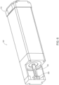
- FIG. 1 is an isometric view of an integrated motor actuator system (or actuator) 100 with housing 110, data and power connectors 115, and a thrust tube or output rod 120 adapted for linear motion along the actuator axis A.
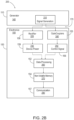
- FIG 2A is a block diagram of the actuator system 100 in FIG. 1
- FIG. 2B is a is a process flow chart 200 illustrating conversion of signals S from the power generator system 140 into power for the microcontroller (or controller) 150, and into motor cycle count and positional data for storage in memory 154.
- output rod 120 can be coupled to a machine tool fixture or end effector 125, and adapted to translate along actuator axis A in response to the rotational motion of integrated motor assembly 130.
- Motor assembly (or motor) 130 includes a rotor 132 disposed within a hollow stator assembly (or stator) 133, and coupled to a screw shaft 134 and nut assembly 135 that connects to the output rod 120.
- Actuator system 100 may also include additional components such as a resolver or encoder 136 and one or more bearings 138; e.g., as described in U.S. Publication No. 2019/0048988 A1 , which is incorporated by reference, and as otherwise known in the art.
- An internal power generator system (or generator) 140 can be disposed within the actuator housing 110, for example on, in or adjacent the rotor 132 and stator assembly 133.
- the generator 140 is connected to a controller or monitor circuit 150 with electronic components including a processor (or microprocessor) 152, an optical coupler, isolator or similar receiver 153 and memory 154 provided on one or more respective circuit boards or modules 155, and a substrate 155S (e.g., formed of a non-electrically conductive barrier material with an inlay configured for near-field communication, or other wireless antenna device), disposed in a recess, pocket, cutout or cavity 160 formed in, on or into the outside surface of the actuator housing 110.
- a signal encoder or decoder 156 can also be provided, along with an input/output (I/O) communication interface 157.
- a cover 165 can be provided to seal the recess 160 ( FIG. 1 ), protecting the controller 150 from accidental contact and environmental contamination.
- the cover 165 can be formed of an RF-transparent material, for example plastic or polymer, to facilitate wireless communications between controller 150 and a computing device 180.
- the cover 165 can be made flush with the actuator housing 110, or extend from the housing 110, or be recessed into the housing 110.
- a data bus or signal wires 170 can connect the controller 150 to the internal power generator 140. Additional bus lines or wires 170 can also provide data from one or more internal sensors such as thermal sensors T (e.g., adjacent a bearing component 138 or the shaft and nut assembly 134, 135), vibrational sensors V (e.g., adjacent the shaft and nut assembly 134, 135, or other load-bearing mechanical component), one or load sensors L (e.g., adjacent the output rod 120 or fixture 125), and/or one or more load-bearing, moisture, humidity, or other sensors H.
- thermal sensors T e.g., adjacent a bearing component 138 or the shaft and nut assembly 134, 135
- vibrational sensors V e.g., adjacent the shaft and nut assembly 134, 135, or other load-bearing mechanical component
- load sensors L e.g., adjacent the output rod 120 or fixture 125
- load-bearing moisture, humidity, or other sensors H.
- one possible implementation is in an actuator 100 where the controller 150 has processor and memory electronics disposed on one or more circuit boards 155, mounted to the outside of the actuator housing 110 in a small recess, pocket, cutout or cavity 160.
- Recess 160 can be configured to closely fit the circuit board or boards 155 (or other electronic components) making up the controller 150, reducing size requirements.
- a signal bus or signal wires 170 connect the power generator 140 (and various sensors T, V, H, etc.) to the controller 150.
- the bus or wires 170 can be fed through the actuator housing 110 via one or more connectors 175, e.g., on the inside of the recess 160, connecting with one or more circuit boards 155 of the controller 150.
- the controller 150 can be disposed in the recess or cavity 160, as shown in FIG. 1 , and hidden under a protective plastic, polymer, or metal cover or overlay 165.
- cover 165 can be provided in durable, elastic form applied to the exterior of the actuator housing 110 with an adhesive (e.g., with a self-adhesive cover 165, similar to a sticker), or cover 165 can be attached to actuator housing 110 via one more screws, bolts, clips, or similar mechanical attachments.
- the controller 150 can be configured to operate in a passive manner; that is, counting the number of revolutions, cycles or direction changes of the motor assembly 130 when the actuator 100 is operational (e.g., when the motor 130 is running), or when the motor 130 is operating at or above a preselected speed (e.g., a minimum rotational speed).
- the data generated by controller 150 can be stored in memory 154 and accessed either when actuator 100 is operational (e.g., with external power on and motor 130 running) or when the actuator 100 is not in operation (e.g., with the external power either on or off, and motor 130 not running). The data can thus be accessed either when actuator 100 is moving (with output rod 120 in linear motion responsive to the rotation of motor 130), or not moving (with output rod 120 and motor 130 stationary).
- controller 150 need not be powered to access the data stored in memory 154. Rather, an operator could communicate with ("tap into") the data using a computing device 180 configured for near-field communication (NFC), or other wireless communication with controller 150.
- Suitable wireless computing devices 180 include smart phones, tablet computers, and other personal or mobile computing devices, and dedicated wireless communications devices 180, for example a dedicated computer or hub device 180 connected to a data center 185.
- a wireless input/output (I/O) interface 157 can be provided on one or more of the electronic circuit boards or modules 155, and configured to transfer data from microprocessor 152 and memory 154 to the computing device 180.
- Power for operation of the controller 150 can be generated from the signals from the generator 140, using a rectifier and regulator circuit 158 to condition a standard DC power supply, which can be conditioned and/or stored in a capacitive or battery-based power condition and storage circuit 159.
- controller 150 receives signals from the power generator system 140; e.g., as a series of voltage or current pulses over signal wires 170. A portion of the energy is converted to power for operation of the microprocessor 150, memory 154, and other components such as interface 157, for example using a rectifier/regulator circuit 158. A portion of the energy can be stored in a battery or capacitive storage circuit 159, for operation of controller 150 when the motor 130 is not operating, and wires 170 do not provide signals.
- Controller 150 can also count the signals from the generator 140, in order to determine the number of motor rotations or cycles. The magnitude and polarity of the signals can be used to determine the rotational direction and power output, from which the position of and loading on the output rod 120 can be determined.
- the microprocessor 152 can also execute code to determine additional operational parameters such as temperature, moisture level, and vibrational state, for example using data from temperature, humidity, and vibrational sensors in a sensor array 145. Similar sensors may be disposed on one of the circuit boards 155 of microprocessor 150.
- microprocessor 152 can be stored in memory 154, communicated directly to computing device 180, or both. Communications with device 180 can be performed via BLE, LoRa or other lo-range, mid-range or long-range, low-power RF wireless communication system, or other wired or wireless communication standard, as described herein, or as known in the art.
- Suitable computing devices 180 can be provided to the operator of the actuator system 100, or to the manufacturer or maintenance personnel, in any combination, inclusive or exclusive. Another configuration would include a central dedicated computer or "hub” device 180, within communication range of one or more actuator systems or devices 100 with supported controllers 150, and connected to a data center 185; e.g. via the internet or a cloud connection.
- controllers 150 on each actuator 100 can maintain constant or synchronous communication with computing device 180 and data center 185 while the respective actuators 100 are running.
- the respective controllers 150 do not necessarily send updates to the device 180, and the data center 185 may display the most recent data, as it was last received.
- controllers 150 can perform intermittent or asynchronous communications with hub 180 during actuator down time, or a combination of synchronous and asynchronous communications.
- FIG. 2B is a hybrid process flow and system chart 200 illustrating how signals generated by the power generator system 140 (step 210) can be converted into operational data and other information by a suitable controller.
- the generator 140 generates current or voltage pulses based on motor operation.
- One or more sensor signals can also be provided to the controller 150, such as temperature, humidity, or vibrational state sensed at or proximate any of the internal actuator system components. These signals can be transmitted over wires 170 to an electronic-based controller 150 with one or more circuit boards 155, or via a wireless connection, or a combination thereof (e.g., with hard-wired signals for power delivery and motor cycle counts, and wireless sensor signals).
- Controller 150 includes a power generation circuit 158 with a rectifier and regulator or similar components configured to generate power (step 220) from the voltage or current pulses transmitted along wires 170.
- the power can be provided in a standardized DC format, suitable for operation of the microprocessor 152, the optical coupler/isolator or receiver 153, memory 154, interface 157, and other electronic components on circuit board (or boards) 155.
- the power can also be filtered and conditioned and/or stored (step 230) in capacitive array or battery circuit 159, for operation of controller 150 when wires 170 do not necessarily carry signals.
- Controller 150 also includes a signal processing circuit with one or more signal receivers such as an optical coupler or optical isolator 153, configured to receive and isolate the current or voltage pulses and sensor signals (step 240), reducing ground loops, noise and cross-talk for improved signal processing.
- Control signals can be generated (step 250) from the output of the optical coupler/isolator 153; e.g., using a digital signal encoder or decoder 156, for data processing (step 260) by the microprocessor 152.
- the processed data can be stored in memory 154 (step 270), and communicated via a wireless or wired I/O interface 157 (step 280), as described herein.
- the signals from the generator assembly 140 when passed through controller electronics including the rectifier and regulator 158 (step 220), can be converted to via a DC power conditioner/storage circuit 159 (step 230), for operation of the processor 152, receiver 153, memory 154, decoder 156, I/O interface 157, and other electronic components 152 of the controller 150, disposed on circuit board 155.
- the signals from the generator 140 when passed through a suitable receiver such as an optical coupler or isolator 153 (step 240), can be configured to present as two digital square wave pulse signals, where the pulses are phase shifted from one another other.
- This signal configuration allows the signal encoder/decoder 156 (step 250) and processor 152 to process the signal data (step 260) to determine the direction in which the actuator is running, and to maintain a direction state (e.g., as a binary value) in memory.
- the motor direction state can be stored in memory 154 (step 270), and accessed to determine whether a direction change has occurred, and to increment a corresponding direction reversal count (e.g., indicating a motor cycle phase has been completed in the proximal or distal direction, so that two reversals can indicate a complete cycle, with the thrust rod moving once in each direction).
- a direction change e.g., indicating a motor cycle phase has been completed in the proximal or distal direction, so that two reversals can indicate a complete cycle, with the thrust rod moving once in each direction.
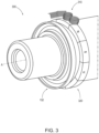
- FIG. 3 is a schematic diagram illustrating a first representative generator assembly 300 for the internal power generator system 140 in an integrated motor actuator, as described herein.
- generator assembly (or generator) 300 includes a number of inductive coils 310, Hall sensors or similar electromagnetic pickups, which can be mounted on the inside of the actuator housing, adjacent a number of corresponding magnetic poles 320 distributed about the end circumference of rotor 132, and configured to sense the induced voltage or electromotive force (emf) induced by the passage of poles 320.
- coils 310 can be provided in the form of N conductive wire windings, where the voltage generated by each coil 310 is proportional to N, and the rate of change of magnetic field (or magnetic flux) through the area defined by the circumference of the coil.
- the generator coils 310 can be directly or indirectly mounted to the inside of the actuator housing, before or after installation of the stator windings, and need not be buried or embedded in potting compound, or other insulating material.
- Magnetic poles 320 can be disposed about the rotor to interact with these coils 310; e.g., in the form of individually placed permanent magnetic poles 320 with alternating N/S orientation, or in the form of a magnetic strip having alternating N/S poles 320.
- the coils 310 can be placed adjacent the existing poles 325 on the rotor 132; e.g., in a surface-mounted permanent magnet (SPM) arrangement, as shown in FIG. 5 (below).
- SPM surface-mounted permanent magnet
- the coils 310 of generator assembly 300 should produce a voltage or current pulse suitable for the requirements of the power generation electronics; e.g., so that the pulses can be voltage rectified, filtered and regulated to supply power for the controller processor and memory.
- the generator assembly 300 can have any suitable number of coils and associated phases, for example two, three, or more, as adapted for conditioning via an optical coupler/isolator or similar receiving device to be encoded as a quadrature signal.
- the same voltage or current pulses generated by coils 310 can be used both for powering the controller circuit, and also to provide the signal information used to calculate motor cycles or rotations of the rotor 132.
- the generator assembly 300 should be designed so that the number of magnetic poles 320 is sufficiently high, such that multiple signal pulses are obtained for each mechanical revolution of the rotor 132.
- This embodiment does not rely on the motor's existing magnets, which interact with stator windings to drive the rotor into rotation about its axis.
- the design should also take into consideration potential cogging torque and drag contributed to operation of the motor system, so that any such additional contributions can be reduced, minimized, or made small or negligible, as compared to the typical actuator power output.
- One approach to a suitable generator design, while managing costs, is to place coils 310 at selected locations extending partly around rotor 132 (and the interior of the actuator housing), space appropriately from magnetic poles 320 to provide good signal strength, while maintaining rotational clearance.
- the poles 320 can be spaced about the entire rotor circumference, as shown in FIG. 3 .
- the signals are fully intact at all times (that is, each coil 310 generates the same number of signals, uniformly and sequentially with respect to rotation of the rotor 132), but a complete set (full circle) of coils 310 is not necessarily required, reducing costs.
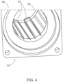
- FIG. 4 illustrates a second representative design for generator assembly (or generator) 300.
- longitudinally extended wire coils 310 are installed around one, two, or more stator teeth 330 on an existing stator assembly 133.
- the coils 310 are configured to pick up signals from the existing rotor magnets, which are used to drive the rotor into rotation.
- These coils 310 may also be sensitive to flux generated by the stator teeth 330, crossing the gap to the adjacent (rotating) rotor poles.
- coils 310 may also be provided in the form of Hall sensors, solid-state pickups, or other electromagnetic devices sensitive to changing magnetic flux, and all of these meanings are encompassed.
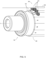
- FIG. 5 illustrates a third representative design for generator assembly (or generator) 300.
- a number of small, generally circular wire coils 310 can be installed prior to potting; e.g., at or adjacent the end turns of stator windings 335, and configured to pick up flux from the existing rotor poles 325 provided to drive the rotor 132, and/or magnetic flux generated by stator elements including stator windings 335 and/or stator teeth 330 (see FIG. 4 ).
- the coils 310 may occupy a relatively small or modest, but otherwise unused space inside the actuator housing, adjacent the end turns of the stator windings 335. Coils 310 can thus generate emf based not only on the passage of magnetic poles 325 (or rotor poles 320; see FIGS. 3 , 8, 9 ), but also from an inductive coupling to stator elements such as the stator teeth 330 and stator windings 335 (see also, e.g., FIGS. 4 , 10 ).
- the flux generated by magnetic poles 320 (or rotor poles 325) varies based on rotational speed
- the flux generated by the stator windings varies based on motor current.
- the amplitude of the voltage or current pulses generated by coils 310 can also be used to determine power delivered to the rotor 132, which can in turn be used to determine loading on the output rod.
- One or more suitable coils 310 can also be inductively coupled to the motor current supply itself (e.g., looped about the motor current conductor), in order to generate power for operation of the controller electronics, with (or without) additional coils 310 configured to sense the passage of generator poles 320 (or rotor poles 325).
- Coils 310 are also not necessarily the sole source of motor cycle information for generator 300.
- a number of Hall sensors 315 can also be provided; e.g., one, two, three or more sensors 315, and configured to sense the passage of magnetic poles 325 on the rotor 132, as shown in FIG. 5 .
- the coils 310 can be adapted for generating current to power the controller electronics (or other electronics), and the sensors 315 can be configured to generate the signals used to determine the direction and number of rotations of the rotor 132 (and/or the number of motor direction changes, and motor cycles).
- Sensors 315 can also be configured to sense the induced voltage or emf generated by the passage of magnetic poles 320 disposed on a rotor 132, shaft 134, or rotary coupling 360 (e.g., as shown in FIGS. 3 , 8 and 9 ), or by stator elements such as stator teeth 330 or stator windings 335 (e.g., as shown in FIGS. 4 and 10 ).
- an integrated controller 150 is disposed in, on or adjacent to the integrated generator device 300; e.g., with direct wired couplings between the controller 150 and generator 300, as described herein.
- This configuration obviates the need for a separate, external mounting arrangement for the controller 150, which can instead be disposed inside the motor or actuator housing, adjacent the pulley 350.
- a suitable RF-transparent window may be provided in the adjacent housing surface, to facilitate wireless communications between controller 150 and an external computing device.
- the generator assembly 300 of FIG. 7 can also be adapted for other configurations of the pulley (or pulley assembly) 150. These include, but are not limited to, high-speed belt-drive actuator systems with a transverse motor mount; e.g., according to U.S. Publication No. 2018/0045284 A1 , which is incorporated by reference herein, in the entirety and for all purposes.
- a suitable pulley assembly 350 with integrated generator 300 and controller 150 could also be deployed in a traditional rod-style linear actuator with a reverse-parallel or transverse motor configuration; e.g., with the motor disposed in a separate motor housing mounted to the actuator, and using a belt, chain, shaft or gearing system to couple the motor to the actuator shaft. More generally, the shaft can also be rotationally fixed, with the motor configured to rotate the nut about the shaft.
- FIG. 8 illustrates a sixth representative design for generator assembly (generator) 300.
- generator assembly 300 is shaft-mounted, with a set of coils 310 disposed adjacent a corresponding set of alternating magnetic poles 320, which are disposed about the circumference of the shaft 324.
- the poles 320 can be formed of individual magnets with alternating magnetic poles 320, disposed sequentially around the shaft 312, as a magnetic strip or ring magnet with alternating poles 320, or as a ring-shaped magnetic element with diametrically opposed poles 320.
- This configuration can be used in an integrated motor actuator, or in a reverse parallel-mount actuator or transverse motor mount system.
- FIG. 9 illustrates a seventh representative design for generator assembly (generator) 300.
- generator assembly 300 includes a number of coils 310 disposed adjacent a set of alternating poles 320 that are distributed about the circumference of a rotary coupler (or coupling) 360.
- generator assembly 300 can be used in an end-mounted motor actuator system, where the motor is coupled to a shaft via coupling 360, or in a range of other actuator systems, using such a motor coupling 360.
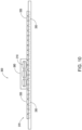
- FIG. 10 illustrates an eighth representative design for generator assembly (generator) 300, applicable to linear motor designs.
- generator assembly 300 includes a number of coils 310 disposed adjacent a linear stator assembly 370, with a number of stator elements comprising stator windings 335 and/or stator teeth 330 distributed longitudinally along the stator assembly 370.
- a processor can be configured to generate a status indicator based on analysis of operational conditions characterized by the sensor data, with respect to the model.
- the processor an also be configured to determine the travel distance of the thrust rod based on the position, and to determine work done by the actuator system based on the travel distance and the motor current delivered to the motor.
- the status indicator can be representative of wear on a component of the motor actuator system, based on the travel distance and the work done.
- An interface can be configured to communicate the status indicator to a control device; e.g., where the status indicator is further representative of the component temperature in relation to at least one normal operating mode of the actuator system, and/or predictive of component failure based on the component temperature in relation to at least one of the failure modes.
- the processor can be configured to estimate one or more of: the total number of cycles based on counting the number of motor rotations, the total number of cycles based on counting the number or motor rotation direction changes, the temperature range for specific components, at which one or more of the motor rotation direction changes happen, and a status indicator that contains data on the conditions in which the system has been operated, and/or preventative maintenance that may indicated, due, or past due.
- An interface can be configured to communicate the status indicator and cycle counts to a control device configured for operating the motor actuator system; e.g., where the status indicator is further representative of the component temperature in relation to at least one normal operating modes of the actuator system, and/or predictive of component failure based on the component temperature in relation to at least one failure mode of the actuator system.
- the electronics does not require internal batteries, capacitors or other storage components to store externally generated power for later use.
- the electronics may include internal batteries, capacitors or other storage components to store energy provided by the generator, based on inductive energy pickup from rotation of the motor.
- the power required by the processor and memory electronics to compute the cycle count can be provided via the signals from the generator.
- the generator may only provide the signals when a changing magnetic field is presented by operation of the actuator motor, for example through inductive pickup in a number of coils disposed adjacent alternating magnetic poles on the rotor.
- the direction state can be accessed when determining the direction, to determine whether a direction change has occurred, and a direction reversal count can be incremented.
- the actuator system can include an internal, passive generator configured for both electrical power and motor cycle signal generation.
- the generator can include a number of wire coils or other inductive pickups; e.g. wire coils wrapped N times, and connected to a controller with processor and memory electronics via a rectifier and regulator, and an optical coupler.
- An end mounted version of the generator can also be provided.
- This configuration can be provided off-the-shelf, or specially adapted to couple to the end of the rotating shaft. This configuration could be applied to actuator designs that have an exposed shaft end.
- the generator design can also be flat or linear, with alternating magnetic poles disposed in a line arrangement, passing by a set of coils. This configuration could be installed on a linear motor, or a linear slide actuator.
- Example 2 follows the system of Example 1, where the processor is adapted to estimate one or more of:
- Example 5 follows a method according to Example 3, where one or more of:
Landscapes
- Engineering & Computer Science (AREA)
- Power Engineering (AREA)
- Microelectronics & Electronic Packaging (AREA)
Applications Claiming Priority (1)
| Application Number | Priority Date | Filing Date | Title |
|---|---|---|---|
| US202263352870P | 2022-06-16 | 2022-06-16 |
Publications (1)
| Publication Number | Publication Date |
|---|---|
| EP4293893A1 true EP4293893A1 (de) | 2023-12-20 |
Family
ID=86851649
Family Applications (1)
| Application Number | Title | Priority Date | Filing Date |
|---|---|---|---|
| EP23179476.9A Pending EP4293893A1 (de) | 2022-06-16 | 2023-06-15 | Passiver vorrichtungsmonitor |
Country Status (3)
| Country | Link |
|---|---|
| US (1) | US20230412050A1 (de) |
| EP (1) | EP4293893A1 (de) |
| CA (1) | CA3203776A1 (de) |
Families Citing this family (1)
| Publication number | Priority date | Publication date | Assignee | Title |
|---|---|---|---|---|
| TWI697165B (zh) * | 2019-05-30 | 2020-06-21 | 陳慶祥 | 用於刺青機且可供輸出方波之直流供電單元 |
Citations (7)
| Publication number | Priority date | Publication date | Assignee | Title |
|---|---|---|---|---|
| US20140339943A1 (en) * | 2013-05-16 | 2014-11-20 | Honeywell International Inc. | Energy harvester and rotating shaft vibration sensor |
| US20160116304A1 (en) * | 2013-05-15 | 2016-04-28 | Iai Corporation | Rotation angle detection system, rotation angle detection method, rotation angle detection unit, and synchronous motor control system |
| EP2776211B1 (de) * | 2011-11-11 | 2016-06-15 | Dino Paoli S.r.l. | Zykluszähler |
| US20180045284A1 (en) | 2015-02-23 | 2018-02-15 | Tolomatic, Inc. | High speed rod-style linear actuator |
| US20190048988A1 (en) | 2015-09-14 | 2019-02-14 | Tolomatic, Inc. | Actuator diagnostics and prognostics |
| KR20190038822A (ko) * | 2016-08-11 | 2019-04-09 | 섀플러 테크놀로지스 아게 운트 코. 카게 | 자기 센서 장치와 액추에이터를 상호 조정하기 위한 방법, 그리고 액추에이터 및 자기 센서 장치를 갖는 액추에이터 장치 |
| WO2019133780A1 (en) * | 2017-12-28 | 2019-07-04 | Abb Schweiz Ag | Rotating power electronics in synchronous machine excitation |
-
2023
- 2023-06-15 EP EP23179476.9A patent/EP4293893A1/de active Pending
- 2023-06-16 CA CA3203776A patent/CA3203776A1/en active Pending
- 2023-06-16 US US18/210,803 patent/US20230412050A1/en active Pending
Patent Citations (7)
| Publication number | Priority date | Publication date | Assignee | Title |
|---|---|---|---|---|
| EP2776211B1 (de) * | 2011-11-11 | 2016-06-15 | Dino Paoli S.r.l. | Zykluszähler |
| US20160116304A1 (en) * | 2013-05-15 | 2016-04-28 | Iai Corporation | Rotation angle detection system, rotation angle detection method, rotation angle detection unit, and synchronous motor control system |
| US20140339943A1 (en) * | 2013-05-16 | 2014-11-20 | Honeywell International Inc. | Energy harvester and rotating shaft vibration sensor |
| US20180045284A1 (en) | 2015-02-23 | 2018-02-15 | Tolomatic, Inc. | High speed rod-style linear actuator |
| US20190048988A1 (en) | 2015-09-14 | 2019-02-14 | Tolomatic, Inc. | Actuator diagnostics and prognostics |
| KR20190038822A (ko) * | 2016-08-11 | 2019-04-09 | 섀플러 테크놀로지스 아게 운트 코. 카게 | 자기 센서 장치와 액추에이터를 상호 조정하기 위한 방법, 그리고 액추에이터 및 자기 센서 장치를 갖는 액추에이터 장치 |
| WO2019133780A1 (en) * | 2017-12-28 | 2019-07-04 | Abb Schweiz Ag | Rotating power electronics in synchronous machine excitation |
Also Published As
| Publication number | Publication date |
|---|---|
| US20230412050A1 (en) | 2023-12-21 |
| CA3203776A1 (en) | 2023-12-16 |
Similar Documents
| Publication | Publication Date | Title |
|---|---|---|
| EP2112461B1 (de) | Messtaster mit Stromgenerator | |
| EP4293893A1 (de) | Passiver vorrichtungsmonitor | |
| US20180026496A1 (en) | Motor having function of generating and feeding electric power at coil end portion | |
| GB2578957A (en) | Position detecting system and method for detecting a movement of a machine | |
| US10338571B2 (en) | Motor controller and methods of wirelessly reprogramming motor controller | |
| RU2526864C2 (ru) | Сенсорное устройство для тока подшипника с преобразователем энергии | |
| CN112752671B (zh) | 用于向轨道车辆中的传感器装置供应能量的设备和方法 | |
| US7378815B2 (en) | Speed monitoring device | |
| US10191482B1 (en) | Motor controller and methods of monitoring motor status | |
| CN103248284A (zh) | 线性磁轴电机专用驱动器 | |
| JP2014230363A (ja) | 電動機および空気調和機 | |
| JP2017158235A (ja) | モータユニットおよびモータシステム | |
| GB2579121A (en) | Position detection system and method of detecting a movement of a machine | |
| Xu et al. | Energy-autonomous on-rotor RPM sensor using variable reluctance energy harvesting | |
| KR20160010820A (ko) | 접촉하는 전기공급체가 필요 없는 직류 모터 | |
| CN212412822U (zh) | 齿轮箱远程状态监测系统自充电装置 | |
| CN218995600U (zh) | 一种电机检测装置 | |
| CN111641248A (zh) | 齿轮箱远程状态监测系统自充电装置 | |
| Nemec et al. | Design of an electronic odometer for DC motors | |
| CN2859459Y (zh) | 无刷测位解析器 | |
| CN216625614U (zh) | 一种电机控制系统 | |
| JP7358964B2 (ja) | センサ付き軸受および計測システム | |
| RU94332U1 (ru) | Устройство для определения угловых перемещений платформы грузоподъемной машины | |
| CN219287323U (zh) | 一种无刷电机 | |
| EP3658876B1 (de) | Wandlervorrichtung für eine drehwelle einer maschine |
Legal Events
| Date | Code | Title | Description |
|---|---|---|---|
| PUAI | Public reference made under article 153(3) epc to a published international application that has entered the european phase |
Free format text: ORIGINAL CODE: 0009012 |
|
| STAA | Information on the status of an ep patent application or granted ep patent |
Free format text: STATUS: THE APPLICATION HAS BEEN PUBLISHED |
|
| AK | Designated contracting states |
Kind code of ref document: A1 Designated state(s): AL AT BE BG CH CY CZ DE DK EE ES FI FR GB GR HR HU IE IS IT LI LT LU LV MC ME MK MT NL NO PL PT RO RS SE SI SK SM TR |