EP4293764A1 - Gasket member for solid polymer fuel cell, electrode-electrolyte membrane laminate with gasket member, and solid polymer fuel cell - Google Patents
Gasket member for solid polymer fuel cell, electrode-electrolyte membrane laminate with gasket member, and solid polymer fuel cell Download PDFInfo
- Publication number
- EP4293764A1 EP4293764A1 EP22752805.6A EP22752805A EP4293764A1 EP 4293764 A1 EP4293764 A1 EP 4293764A1 EP 22752805 A EP22752805 A EP 22752805A EP 4293764 A1 EP4293764 A1 EP 4293764A1
- Authority
- EP
- European Patent Office
- Prior art keywords
- gasket member
- base material
- material layer
- fuel cell
- solid polymer
- Prior art date
- Legal status (The legal status is an assumption and is not a legal conclusion. Google has not performed a legal analysis and makes no representation as to the accuracy of the status listed.)
- Pending
Links
Images
Classifications
-
- F—MECHANICAL ENGINEERING; LIGHTING; HEATING; WEAPONS; BLASTING
- F16—ENGINEERING ELEMENTS AND UNITS; GENERAL MEASURES FOR PRODUCING AND MAINTAINING EFFECTIVE FUNCTIONING OF MACHINES OR INSTALLATIONS; THERMAL INSULATION IN GENERAL
- F16J—PISTONS; CYLINDERS; SEALINGS
- F16J15/00—Sealings
- F16J15/02—Sealings between relatively-stationary surfaces
- F16J15/06—Sealings between relatively-stationary surfaces with solid packing compressed between sealing surfaces
- F16J15/10—Sealings between relatively-stationary surfaces with solid packing compressed between sealing surfaces with non-metallic packing
- F16J15/102—Sealings between relatively-stationary surfaces with solid packing compressed between sealing surfaces with non-metallic packing characterised by material
-
- H—ELECTRICITY
- H01—ELECTRIC ELEMENTS
- H01M—PROCESSES OR MEANS, e.g. BATTERIES, FOR THE DIRECT CONVERSION OF CHEMICAL ENERGY INTO ELECTRICAL ENERGY
- H01M8/00—Fuel cells; Manufacture thereof
- H01M8/02—Details
- H01M8/0271—Sealing or supporting means around electrodes, matrices or membranes
- H01M8/028—Sealing means characterised by their material
-
- B—PERFORMING OPERATIONS; TRANSPORTING
- B32—LAYERED PRODUCTS
- B32B—LAYERED PRODUCTS, i.e. PRODUCTS BUILT-UP OF STRATA OF FLAT OR NON-FLAT, e.g. CELLULAR OR HONEYCOMB, FORM
- B32B15/00—Layered products comprising a layer of metal
- B32B15/04—Layered products comprising a layer of metal comprising metal as the main or only constituent of a layer, which is next to another layer of the same or of a different material
- B32B15/08—Layered products comprising a layer of metal comprising metal as the main or only constituent of a layer, which is next to another layer of the same or of a different material of synthetic resin
-
- B—PERFORMING OPERATIONS; TRANSPORTING
- B32—LAYERED PRODUCTS
- B32B—LAYERED PRODUCTS, i.e. PRODUCTS BUILT-UP OF STRATA OF FLAT OR NON-FLAT, e.g. CELLULAR OR HONEYCOMB, FORM
- B32B27/00—Layered products comprising a layer of synthetic resin
- B32B27/06—Layered products comprising a layer of synthetic resin as the main or only constituent of a layer, which is next to another layer of the same or of a different material
- B32B27/08—Layered products comprising a layer of synthetic resin as the main or only constituent of a layer, which is next to another layer of the same or of a different material of synthetic resin
-
- B—PERFORMING OPERATIONS; TRANSPORTING
- B32—LAYERED PRODUCTS
- B32B—LAYERED PRODUCTS, i.e. PRODUCTS BUILT-UP OF STRATA OF FLAT OR NON-FLAT, e.g. CELLULAR OR HONEYCOMB, FORM
- B32B27/00—Layered products comprising a layer of synthetic resin
- B32B27/12—Layered products comprising a layer of synthetic resin next to a fibrous or filamentary layer
-
- B—PERFORMING OPERATIONS; TRANSPORTING
- B32—LAYERED PRODUCTS
- B32B—LAYERED PRODUCTS, i.e. PRODUCTS BUILT-UP OF STRATA OF FLAT OR NON-FLAT, e.g. CELLULAR OR HONEYCOMB, FORM
- B32B27/00—Layered products comprising a layer of synthetic resin
- B32B27/28—Layered products comprising a layer of synthetic resin comprising synthetic resins not wholly covered by any one of the sub-groups B32B27/30 - B32B27/42
- B32B27/281—Layered products comprising a layer of synthetic resin comprising synthetic resins not wholly covered by any one of the sub-groups B32B27/30 - B32B27/42 comprising polyimides
-
- B—PERFORMING OPERATIONS; TRANSPORTING
- B32—LAYERED PRODUCTS
- B32B—LAYERED PRODUCTS, i.e. PRODUCTS BUILT-UP OF STRATA OF FLAT OR NON-FLAT, e.g. CELLULAR OR HONEYCOMB, FORM
- B32B27/00—Layered products comprising a layer of synthetic resin
- B32B27/28—Layered products comprising a layer of synthetic resin comprising synthetic resins not wholly covered by any one of the sub-groups B32B27/30 - B32B27/42
- B32B27/285—Layered products comprising a layer of synthetic resin comprising synthetic resins not wholly covered by any one of the sub-groups B32B27/30 - B32B27/42 comprising polyethers
-
- B—PERFORMING OPERATIONS; TRANSPORTING
- B32—LAYERED PRODUCTS
- B32B—LAYERED PRODUCTS, i.e. PRODUCTS BUILT-UP OF STRATA OF FLAT OR NON-FLAT, e.g. CELLULAR OR HONEYCOMB, FORM
- B32B27/00—Layered products comprising a layer of synthetic resin
- B32B27/28—Layered products comprising a layer of synthetic resin comprising synthetic resins not wholly covered by any one of the sub-groups B32B27/30 - B32B27/42
- B32B27/286—Layered products comprising a layer of synthetic resin comprising synthetic resins not wholly covered by any one of the sub-groups B32B27/30 - B32B27/42 comprising polysulphones; polysulfides
-
- B—PERFORMING OPERATIONS; TRANSPORTING
- B32—LAYERED PRODUCTS
- B32B—LAYERED PRODUCTS, i.e. PRODUCTS BUILT-UP OF STRATA OF FLAT OR NON-FLAT, e.g. CELLULAR OR HONEYCOMB, FORM
- B32B27/00—Layered products comprising a layer of synthetic resin
- B32B27/28—Layered products comprising a layer of synthetic resin comprising synthetic resins not wholly covered by any one of the sub-groups B32B27/30 - B32B27/42
- B32B27/288—Layered products comprising a layer of synthetic resin comprising synthetic resins not wholly covered by any one of the sub-groups B32B27/30 - B32B27/42 comprising polyketones
-
- B—PERFORMING OPERATIONS; TRANSPORTING
- B32—LAYERED PRODUCTS
- B32B—LAYERED PRODUCTS, i.e. PRODUCTS BUILT-UP OF STRATA OF FLAT OR NON-FLAT, e.g. CELLULAR OR HONEYCOMB, FORM
- B32B27/00—Layered products comprising a layer of synthetic resin
- B32B27/32—Layered products comprising a layer of synthetic resin comprising polyolefins
-
- B—PERFORMING OPERATIONS; TRANSPORTING
- B32—LAYERED PRODUCTS
- B32B—LAYERED PRODUCTS, i.e. PRODUCTS BUILT-UP OF STRATA OF FLAT OR NON-FLAT, e.g. CELLULAR OR HONEYCOMB, FORM
- B32B27/00—Layered products comprising a layer of synthetic resin
- B32B27/34—Layered products comprising a layer of synthetic resin comprising polyamides
-
- B—PERFORMING OPERATIONS; TRANSPORTING
- B32—LAYERED PRODUCTS
- B32B—LAYERED PRODUCTS, i.e. PRODUCTS BUILT-UP OF STRATA OF FLAT OR NON-FLAT, e.g. CELLULAR OR HONEYCOMB, FORM
- B32B5/00—Layered products characterised by the non- homogeneity or physical structure, i.e. comprising a fibrous, filamentary, particulate or foam layer; Layered products characterised by having a layer differing constitutionally or physically in different parts
- B32B5/02—Layered products characterised by the non- homogeneity or physical structure, i.e. comprising a fibrous, filamentary, particulate or foam layer; Layered products characterised by having a layer differing constitutionally or physically in different parts characterised by structural features of a fibrous or filamentary layer
- B32B5/022—Non-woven fabric
-
- H—ELECTRICITY
- H01—ELECTRIC ELEMENTS
- H01M—PROCESSES OR MEANS, e.g. BATTERIES, FOR THE DIRECT CONVERSION OF CHEMICAL ENERGY INTO ELECTRICAL ENERGY
- H01M8/00—Fuel cells; Manufacture thereof
- H01M8/02—Details
- H01M8/0271—Sealing or supporting means around electrodes, matrices or membranes
- H01M8/0273—Sealing or supporting means around electrodes, matrices or membranes with sealing or supporting means in the form of a frame
-
- H—ELECTRICITY
- H01—ELECTRIC ELEMENTS
- H01M—PROCESSES OR MEANS, e.g. BATTERIES, FOR THE DIRECT CONVERSION OF CHEMICAL ENERGY INTO ELECTRICAL ENERGY
- H01M8/00—Fuel cells; Manufacture thereof
- H01M8/02—Details
- H01M8/0271—Sealing or supporting means around electrodes, matrices or membranes
- H01M8/0276—Sealing means characterised by their form
-
- H—ELECTRICITY
- H01—ELECTRIC ELEMENTS
- H01M—PROCESSES OR MEANS, e.g. BATTERIES, FOR THE DIRECT CONVERSION OF CHEMICAL ENERGY INTO ELECTRICAL ENERGY
- H01M8/00—Fuel cells; Manufacture thereof
- H01M8/02—Details
- H01M8/0271—Sealing or supporting means around electrodes, matrices or membranes
- H01M8/028—Sealing means characterised by their material
- H01M8/0284—Organic resins; Organic polymers
-
- H—ELECTRICITY
- H01—ELECTRIC ELEMENTS
- H01M—PROCESSES OR MEANS, e.g. BATTERIES, FOR THE DIRECT CONVERSION OF CHEMICAL ENERGY INTO ELECTRICAL ENERGY
- H01M8/00—Fuel cells; Manufacture thereof
- H01M8/02—Details
- H01M8/0271—Sealing or supporting means around electrodes, matrices or membranes
- H01M8/0286—Processes for forming seals
-
- H—ELECTRICITY
- H01—ELECTRIC ELEMENTS
- H01M—PROCESSES OR MEANS, e.g. BATTERIES, FOR THE DIRECT CONVERSION OF CHEMICAL ENERGY INTO ELECTRICAL ENERGY
- H01M8/00—Fuel cells; Manufacture thereof
- H01M8/10—Fuel cells with solid electrolytes
-
- H—ELECTRICITY
- H01—ELECTRIC ELEMENTS
- H01M—PROCESSES OR MEANS, e.g. BATTERIES, FOR THE DIRECT CONVERSION OF CHEMICAL ENERGY INTO ELECTRICAL ENERGY
- H01M8/00—Fuel cells; Manufacture thereof
- H01M8/10—Fuel cells with solid electrolytes
- H01M8/1004—Fuel cells with solid electrolytes characterised by membrane-electrode assemblies [MEA]
-
- B—PERFORMING OPERATIONS; TRANSPORTING
- B32—LAYERED PRODUCTS
- B32B—LAYERED PRODUCTS, i.e. PRODUCTS BUILT-UP OF STRATA OF FLAT OR NON-FLAT, e.g. CELLULAR OR HONEYCOMB, FORM
- B32B2255/00—Coating on the layer surface
- B32B2255/26—Polymeric coating
-
- B—PERFORMING OPERATIONS; TRANSPORTING
- B32—LAYERED PRODUCTS
- B32B—LAYERED PRODUCTS, i.e. PRODUCTS BUILT-UP OF STRATA OF FLAT OR NON-FLAT, e.g. CELLULAR OR HONEYCOMB, FORM
- B32B2307/00—Properties of the layers or laminate
- B32B2307/30—Properties of the layers or laminate having particular thermal properties
- B32B2307/31—Heat sealable
-
- B—PERFORMING OPERATIONS; TRANSPORTING
- B32—LAYERED PRODUCTS
- B32B—LAYERED PRODUCTS, i.e. PRODUCTS BUILT-UP OF STRATA OF FLAT OR NON-FLAT, e.g. CELLULAR OR HONEYCOMB, FORM
- B32B2307/00—Properties of the layers or laminate
- B32B2307/50—Properties of the layers or laminate having particular mechanical properties
- B32B2307/54—Yield strength; Tensile strength
-
- B—PERFORMING OPERATIONS; TRANSPORTING
- B32—LAYERED PRODUCTS
- B32B—LAYERED PRODUCTS, i.e. PRODUCTS BUILT-UP OF STRATA OF FLAT OR NON-FLAT, e.g. CELLULAR OR HONEYCOMB, FORM
- B32B2307/00—Properties of the layers or laminate
- B32B2307/70—Other properties
- B32B2307/732—Dimensional properties
- B32B2307/737—Dimensions, e.g. volume or area
- B32B2307/7375—Linear, e.g. length, distance or width
- B32B2307/7376—Thickness
-
- B—PERFORMING OPERATIONS; TRANSPORTING
- B32—LAYERED PRODUCTS
- B32B—LAYERED PRODUCTS, i.e. PRODUCTS BUILT-UP OF STRATA OF FLAT OR NON-FLAT, e.g. CELLULAR OR HONEYCOMB, FORM
- B32B2581/00—Seals; Sealing equipment; Gaskets
-
- H—ELECTRICITY
- H01—ELECTRIC ELEMENTS
- H01M—PROCESSES OR MEANS, e.g. BATTERIES, FOR THE DIRECT CONVERSION OF CHEMICAL ENERGY INTO ELECTRICAL ENERGY
- H01M8/00—Fuel cells; Manufacture thereof
- H01M8/10—Fuel cells with solid electrolytes
- H01M2008/1095—Fuel cells with polymeric electrolytes
-
- H—ELECTRICITY
- H01—ELECTRIC ELEMENTS
- H01M—PROCESSES OR MEANS, e.g. BATTERIES, FOR THE DIRECT CONVERSION OF CHEMICAL ENERGY INTO ELECTRICAL ENERGY
- H01M2300/00—Electrolytes
- H01M2300/0017—Non-aqueous electrolytes
- H01M2300/0065—Solid electrolytes
- H01M2300/0082—Organic polymers
-
- Y—GENERAL TAGGING OF NEW TECHNOLOGICAL DEVELOPMENTS; GENERAL TAGGING OF CROSS-SECTIONAL TECHNOLOGIES SPANNING OVER SEVERAL SECTIONS OF THE IPC; TECHNICAL SUBJECTS COVERED BY FORMER USPC CROSS-REFERENCE ART COLLECTIONS [XRACs] AND DIGESTS
- Y02—TECHNOLOGIES OR APPLICATIONS FOR MITIGATION OR ADAPTATION AGAINST CLIMATE CHANGE
- Y02E—REDUCTION OF GREENHOUSE GAS [GHG] EMISSIONS, RELATED TO ENERGY GENERATION, TRANSMISSION OR DISTRIBUTION
- Y02E60/00—Enabling technologies; Technologies with a potential or indirect contribution to GHG emissions mitigation
- Y02E60/30—Hydrogen technology
- Y02E60/50—Fuel cells
-
- Y—GENERAL TAGGING OF NEW TECHNOLOGICAL DEVELOPMENTS; GENERAL TAGGING OF CROSS-SECTIONAL TECHNOLOGIES SPANNING OVER SEVERAL SECTIONS OF THE IPC; TECHNICAL SUBJECTS COVERED BY FORMER USPC CROSS-REFERENCE ART COLLECTIONS [XRACs] AND DIGESTS
- Y02—TECHNOLOGIES OR APPLICATIONS FOR MITIGATION OR ADAPTATION AGAINST CLIMATE CHANGE
- Y02P—CLIMATE CHANGE MITIGATION TECHNOLOGIES IN THE PRODUCTION OR PROCESSING OF GOODS
- Y02P70/00—Climate change mitigation technologies in the production process for final industrial or consumer products
- Y02P70/50—Manufacturing or production processes characterised by the final manufactured product
Definitions
- the present disclosure relates to a gasket member for a solid polymer fuel cell, a gasket member-attached electrode-electrolyte membrane laminate, and a solid polymer fuel cell.
- Fuel cells are cells that include an electrolyte and an electrode disposed on both surfaces thereof and that generate power by an electrochemical reaction between hydrogen and oxygen, and generate only water during the power generation. Since the fuel cells thus do not generate an environmental-burden gas such as carbon dioxide unlike conventional internal-combustion engines, they are expected to be widely used as next-generation clean energy systems.
- a solid polymer fuel cell has a relatively low operating temperature and low electrolyte resistance and can in addition obtain high output due to the use of a highly active catalyst even when being small, and are therefore expected to be in practical use soon as a domestic cogeneration system and the like.
- this solid polymer fuel cell For the production of this solid polymer fuel cell, first, a solid polymer electrolyte membrane having proton conductivity is prepared, an anode catalyst layer is formed on one surface of this electrolyte membrane and a cathode catalyst layer is formed on the other surface to produce a catalyst layer-electrolyte membrane laminate, and further a gas diffusion layer is formed on the catalyst layers to produce an electrode-electrolyte membrane laminate. Then, on this electrode-electrolyte membrane laminate, a gasket and a separator are placed to complete a solid polymer fuel cell (see, for example, Patent Document 1).
- Patent Document 1 Japanese Patent Laid-open Publication No. 2013-218876
- the members constituting the fuel cell are required to have high hydrolysis resistance.
- the output density of the fuel cell can be improved by increasing the operating temperature thereof, the fuel cell is required to tolerate the use in a high-temperature environment (for example, 100°C or more) from the viewpoint of reducing the size of the fuel cell.
- a gasket member among the members constituting the fuel cell does not always have sufficient hydrolysis resistance in a high-temperature environment.
- the gasket member does not have sufficient hydrolysis resistance in a high-temperature environment, a problem may possibly occur in which the gasket member is hydrolyzed and a fuel is leaked.
- a main object of the present disclosure is to provide a gasket member for a solid polymer fuel cell, the gasket member having excellent hydrolysis resistance in a high-temperature environment.
- a laminate including a laminate that includes a base material layer and an adhesive layer disposed on both sides of the base material layer, and that has a retention of elongation at break of 60% or more after left in 120°C water for 300 hours has excellent hydrolysis resistance in a high-temperature environment and can suitably be used as a gasket member for a solid polymer fuel cell.
- a gasket member for a solid polymer fuel cell including a laminate that includes a base material layer and an adhesive layer disposed on both sides of the base material layer, the laminate having a retention of elongation at break of 60% or more after left in 120°C water for 300 hours.
- the present disclosure can provide a gasket member for a solid polymer fuel cell, the gasket member having excellent hydrolysis resistance in a high-temperature environment.
- the present disclosure can also provide a gasket member-attached electrode-electrolyte membrane laminate including the gasket member, and a solid polymer fuel cell.
- a gasket member, according to the present disclosure, for a solid polymer fuel cell is characterized by including a laminate that includes at least a base material layer and an adhesive layer disposed on both sides of the base material layer, the laminate having a retention of elongation at break of 60% or more after left in 120°C water for 300 hours.
- the gasket member, according to the present disclosure, for a solid polymer fuel cell has excellent hydrolysis resistance in a high-temperature environment.
- the gasket member, according to the present disclosure, for a solid polymer fuel cell is, as described later, a gasket member to be disposed between an electrolyte membrane and a separator of a solid polymer fuel cell, and is applicable to a wide range of solid polymer fuel cells.
- a numerical range indicated by the term “A to B” means “A or more” and “B or less”.
- the expression of "2 to 15 mm” means 2 mm or more and 15 mm or less.
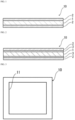
- a gasket member 10, for a solid polymer fuel cell includes, as shown in, for example, Fig. 1 , a laminate that includes at least a base material layer 1 and an adhesive layer 2 disposed on both sides of the base material layer 1. That is, the gasket member 10 includes a laminate that includes at least the adhesive layer 2, the base material layer 1, and the adhesive layer 2 layered in this order.
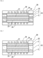
- the adhesive layer 2 on both sides in the gasket member 10 constitutes the outermost layer of the gasket member 10, and the adhesive layer 2 on one side is disposed on the side of an electrolyte membrane 21 and the adhesive layer 2 on the other side is disposed on the side of a separator 25 (see Fig. 6 ).
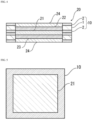
- the gasket member 10 is, for example, disposed to surround the periphery of an electrode-electrolyte membrane laminate (see schematic views of a gasket member-attached electrode-electrolyte membrane laminate in Figs. 4 and 5 ). Accordingly, this gasket member 10 includes an aperture 11 for inserting catalyst layers 22, 23 and a gas diffusion layer 24 (see Fig. 3 ).
- the gasket member 10 may also include an anchor coat layer 3 on at least one of surfaces of the base material layer 1.
- the base material layer 1 is formed of a film
- the disposition of the anchor coat layer 3 between the base material layer 1 and the adhesive layer 2 can increase adhesiveness between the base material layer 1 and the adhesive layer 2.
- the gasket member 10 preferably includes the anchor coat layer 3 on both surfaces of the base material layer 1. That is, the gasket member 10 more preferably includes a laminate that includes at least the adhesive layer 2, the anchor coat layer 3, the base material layer 1, the anchor coat layer 3, and the adhesive layer 2 layered in this order.
- the thickness (total thickness) of the laminate included in the gasket member 10 is adjusted according to the size and the like of the solid polymer fuel cell and is not particularly limited, and examples thereof include about 300 ⁇ m or less, about 200 ⁇ m or less, about 100 ⁇ m or less, and about 50 ⁇ m or less; and about 30 ⁇ m or more, about 100 ⁇ m or more, about 200 ⁇ m or more, and about 250 ⁇ m or more.
- Preferable ranges of the thickness (total thickness) of the laminate included in the gasket member 10 include about 30 to 300 ⁇ m, about 30 to 200 ⁇ m, about 30 to 100 ⁇ m, about 30 to 50 ⁇ m, about 100 to 300 ⁇ m, about 100 to 200 ⁇ m, about 200 to 300 ⁇ m, and about 250 to 300 ⁇ m.
- the thickness (total thickness) of the laminate included in the gasket member 10 is preferably about 400 ⁇ m or less, more preferably about 300 ⁇ m or less, and preferably about 30 ⁇ m or more, more preferably about 50 ⁇ m or more, still more preferably more than 50 ⁇ m, still more preferably about 100 ⁇ m or more, and preferable ranges thereof include about 30 to 400 ⁇ m, about 30 to 30 ⁇ m, about 50 to 400 ⁇ m, about 50 to 300 ⁇ m, about more than 50 ⁇ m and 400 ⁇ m or less, about more than 50 ⁇ m and 300 ⁇ m or less, about 100 to 400 ⁇ m, and about 100 to 300 ⁇ m.
- the thickness of the base material layer 1 is preferably about 300 ⁇ m or less, more preferably about 200 ⁇ m or less, and preferably about 20 ⁇ m or more, more preferably about 30 ⁇ m or more, still more preferably 50 ⁇ m or more, and preferable ranges thereof include about 20 to 300 ⁇ m, about 20 to 200 ⁇ m, about 30 to 300 ⁇ m, about 30 to 200 ⁇ m, about 50 to 300 ⁇ m, and about 50 to 200 ⁇ m.
- the thickness of the adhesive layer 2 is preferably about 200 ⁇ m or less, more preferably about 100 ⁇ m or less, and preferably about 10 ⁇ m or more, more preferably about 30 ⁇ m or more, and preferable ranges thereof include about 10 to 200 ⁇ m, about 10 to 100 ⁇ m, about 30 to 200 ⁇ m, and about 30 to 100 ⁇ m.
- the thickness (total thickness) of the laminate included in each of the gasket members 10 is preferably about 200 ⁇ m or less, more preferably about 150 ⁇ m or less, and preferably about 25 ⁇ m or more, more preferably about 50 ⁇ m or more, and preferable ranges thereof include about 25 to 200 ⁇ m, about 25 to 150 ⁇ m, about 50 to 200 ⁇ m, and about 50 to 150 ⁇ m.
- the thickness of the base material layer 1 is preferably about 200 ⁇ m or less, more preferably about 150 ⁇ m or less, and preferably about 10 ⁇ m or more, more preferably about 15 ⁇ m or more, and preferable ranges thereof include about 10 to 200 ⁇ m, about 10 to 150 ⁇ m, about 15 to 200 ⁇ m, and about 15 to 150 ⁇ m.
- the thickness of the adhesive layer 2 is preferably about 100 ⁇ m or less, more preferably about 50 ⁇ m or less, and preferably about 3 ⁇ m or more, more preferably about 15 ⁇ m or more, and preferable ranges thereof include about 3 to 100 ⁇ m, about 3 to 50 ⁇ m, about 15 to 100 ⁇ m, and about 15 to 50 ⁇ m.
- a solid polymer fuel cell 30 it is selected as appropriate according to the specification and the like of a solid polymer fuel cell 30 whether one gasket member 10 or two gasket members 10 are used.
- the total thickness of the gasket member 10 and the thickness of the layers may also be selected as appropriate according to the thickness and the like of the solid polymer fuel cell 30.
- the proportion of the total thickness of the base material layer 1, the adhesive layer 2, and the anchor coat layer 3 disposed as necessary to the thickness (total thickness) of the laminate included in the gasket member 10 is preferably 90% or more, more preferably 95% or more, still more preferably 98% or more, further 100%.
- the proportion of the total thickness of these layers to the thickness (total thickness) of the laminate included in the gasket member 10 is preferably 90% or more, more preferably 95% or more, still more preferably 98% or more.
- the proportion of the total thickness of these layers to the thickness (total thickness) of the laminate included in the gasket member 10 is, for example, 80% or more, preferably 90% or more, more preferably 95% or more, still more preferably 98% or more, further 100%.
- the laminate included in the gasket member 10 according to the present disclosure has a retention of elongation at break of 60% or more after left in 120°C water for 300 hours. Due to this property, the gasket member 10 exhibits properties of excellent hydrolysis resistance in a high-temperature environment.
- the method for measuring the retention of elongation at break of the gasket member 10 is as follows.
- the retention of elongation at break is measured by the following method. Specifically, a sample was measured for elongation at break after immersed in 120°C water and left for 300 hours, and the obtained measured value was divided by the elongation at break before the endurance test (initial elongation at break) to obtain a retention of elongation at break.
- the elongation at break was measured by cutting a film into a 15-mm wide (TD) 50-mm long (MD) rectangle, and measuring the elongation of the rectangular film to its break by pulling it using a tensile tester under the conditions of a tensile speed of 200 mm/min and a gauge length of 20 mm.
- the test environment is 23°C and the average value of three measurements was used.
- Retention of elongation at break % elongation at break after endurance test / elongation at break before endurance test initial elongation at break ⁇ 100
- the MD can be determined as the direction parallel to a cross-section in which the average of the diameters of island shapes in the direction perpendicular to the thickness direction of the gasket member is maximum.
- the sea-island structure is confirmed by observing electron micrographs of a cross-section in the length direction of the gasket member and cross-sections (total 10 cross-sections) at angular intervals of 10 degrees from the direction parallel to the cross-section in the length direction to the direction perpendicular to the cross-section in the length direction.
- the shape of each island is observed.
- the linear distance connecting the leftmost end in the perpendicular direction to the thickness direction of the gasket member to the rightmost end in the perpendicular direction is defined as a diameter y.
- the average of the top 20 diameters y in descending order of the diameter y of the island shape is calculated.
- the direction parallel to a cross-section having the largest average of the diameters y of the island shapes is determined as MD.
- the laminate included in the gasket member 10 has a retention of elongation at break of 60% or more, preferably 65% or more, more preferably 70% or more, still more preferably 75% or more, still more preferably 80% or more, particularly preferably 85% or more.
- an effective method for increasing the retention of elongation at break of the laminate included in the gasket member 10 to 60% or more there are, for example, a method for using a resin or metal described later as a material for forming the base material layer 1, and a method for using, among these materials, a resin having a high glass-transition temperature (Tg), or the like.
- Tg glass-transition temperature
- the laminate included in the gasket member 10 has, when left in an environment at a temperature of 150°C for 30 minutes, a hot-shrinkage rate of preferably 30% or less, more preferably 20% or less, still more preferably 10% or less. From the same viewpoint, the laminate included in the gasket member 10 has, when left in an environment at a temperature of 180°C for 30 minutes, a hot-shrinkage rate of preferably 30% or less, more preferably 20% or less, still more preferably 10% or less, still more preferably 3% or less, still more preferably 1% or less, still more preferably 0.5% or less.
- the method for measuring the hot-shrinkage rate of the gasket member 10 is as follows.
- the hot-shrinkage rate is obtained by heating a test piece, which is obtained by cutting a gasket member into a size of 10 cm length (MD) ⁇ 10 cm width (TD), in an oven at 150°C or 180°C for 30 minutes, obtaining a size change ratio between before and after the heating of the test piece in the length direction and the width direction (two directions perpendicular to each other) on the basis of the following equation (I), and calculating, as average values, the absolute values of the size change ratios in the two directions.
- Hot-shrinkage rate % X ⁇ Y / X ⁇ 100 [X: size before heat treatment in oven, Y: size after heat treatment in oven]
- the base material layer 1 is a layer disposed for the purpose of, for example, making it exhibit a function as a base material of the gasket member 10.
- the base material layer 1 is positioned between two adhesive layers 2.
- the base material layer 1 is preferably made from a material having excellent hydrolysis resistance, and preferably contains polysulfone, polyether sulfone, polyphenylsulfone, polyarylate, a polyolefin, a polyamide, a polyimide, polyether ether ketone, polymethyltenpene, polyphenylene oxide, polyphenylene sulfide, a fluororesin, a metal, or the like. When these materials are used to form the base material layer 1, one or two or more thereof may be contained in the base material layer 1.
- polystyrene resin examples include polyethylenes such as low-density polyethylene, medium-density polyethylene, high-density polyethylene and linear low-density polyethylene; ethylene- ⁇ -olefin copolymers; polypropylene such as homopolypropylene, block copolymers of polypropylene (e.g., block copolymers of propylene and ethylene) and random copolymers of polypropylene (e.g., random copolymers of propylene and ethylene); propylene- ⁇ -olefin copolymers; and terpolymers of ethylene-butene-propylene.
- polypropylene is preferable.
- the polyolefin resin in the case of a copolymer may be a block copolymer or a random copolymer.
- the polyolefin-based resin may be an acid-modified polyolefin.
- the base material layer 1 When containing a polyolefin, the base material layer 1 may contain only one polyolefin or two or more polyolefins.
- the acid-modified polyolefin is a polymer with the polyolefin modified by subjecting the polyolefin to block polymerization or graft polymerization with an acid component.
- the polyolefin to be acid-modified the above-mentioned polyolefins, copolymers obtained by copolymerizing polar molecules such as acrylic acid or methacrylic acid with the above-mentioned polyolefins, polymers such as crosslinked polyolefins, or the like can also be used.
- Examples of the acid component to be used for acid modification include carboxylic acids such as maleic acid, acrylic acid, itaconic acid, crotonic acid, maleic anhydride and itaconic anhydride, and anhydrides thereof.
- Examples of preferred acid-modified polyolefins include polyolefins modified with a carboxylic acid or an anhydride thereof, polypropylene modified with a carboxylic acid or an anhydride thereof, maleic anhydride-modified polyolefins, and maleic anhydride-modified polypropylene.
- the base material layer 1 may contain only one acid-modified polyolefin or two or more acid-modified polyolefins.
- polyamides such as aliphatic polyamides such as nylon 6, nylon 66, nylon 610, nylon 12, nylon 46, and copolymers of nylon 6 and nylon 66; hexamethylenediamine-isophthalic acid-terephthalic acid copolymerization polyamides containing a structural unit derived from terephthalic acid and/or isophthalic acid, such as nylon 61, nylon 6T, nylon 6IT and nylon 6I6T (I denotes isophthalic acid and T denotes terephthalic acid), and polyamides containing aromatics, such as polyamide MXD6 (polymethaxylylene adipamide); alicyclic polyamides such as polyamide PACM6 (polybis(4-aminocyclohexyl)methaneadipamide; polyamides copolymerized with a lactam component or an isocyanate component such as 4,4'-diphenylmethane-diisocyanate, and
- the polyamide is particularly preferably one having an ⁇ crystal, and specific examples thereof include aliphatic polyamides such as nylon 6, nylon 66, nylon 46, and a copolymer of nylon 6 and nylon 66.
- Examples of the metal include an aluminum alloy, copper, zinc, titanium, and stainless steel.
- the base material layer 1 preferably contains polysulfone, polyether sulfone, polyphenylsulfone, polyarylate, or a polyolefin, more preferably contains polyether sulfone, polyphenylsulfone, or polyarylate, and still more preferably contains polyphenylsulfone.
- the base material layer 1 is preferably made from at least one resin among these resins, and is particularly preferably made from polyphenylsulfone.
- the base material layer 1 is preferably made from a resin having excellent heat resistance, and the resin forming the base material layer 1 has a glass-transition temperature (Tg) of preferably about 160°C or more, more preferably about 180°C or more, still more preferably about 200°C or more.
- the upper limit of the glass-transition temperature (Tg) is, for example, about 450°C or less.
- the glass-transition temperature (Tg) means a displacement point of a baseline in a DSC curve measured by a differential scanning calorimeter (DSC).
- the form of the base material layer 1 may be a film or a nonwoven fabric.
- the base material layer 1 can suitably be formed of a film of the resin or metal described above.
- the base material layer 1 is in the form of, for example, a nonwoven fabric, the base material layer 1 can suitably be formed of a nonwoven fabric of the resin or metal described above.
- the adhesive layer 2 can be impregnated into gaps in the base material layer 1 that is a nonwoven fabric and physical adhesiveness between the base material layer 1 and the adhesive layer 2 can therefore be increased.
- the adhesiveness between the base material layer 1 and the adhesive layer 2 can sufficiently be increased without disposition of the anchor coat layer 3 described layer, even though the anchor coat layer 3 may still be disposed on a surface of the base material layer 1.
- the anchor coat layer 3 is preferably disposed on a surface of the base material layer 1 from the viewpoint of increasing the adhesiveness between the base material layer 1 and the adhesive layer 2.
- the base material layer 1 may be a single layer, or may include two or more layers. When the base material layer 1 includes two or more layers, the layer-forming material and the thickness may be identical or different between the layers.
- additives may be present such as a filler, a flame retardant, an antiblocking agent, an antioxidant, a light stabilizer, a tackifier, and an antistatic agent.
- specific examples of the additives include particles of metal oxides such as alumina, silica, and titania.
- the additives may be used alone, or may be used in combination of two or more thereof.
- the thickness of the base material layer 1 is adjusted as appropriate according to the size and the like of the solid polymer fuel cell. From the viewpoint of suitably increasing the hydrolysis resistance of the gasket member 10 in a high-temperature environment, the thickness of the base material layer 1 is preferably about 20 ⁇ m or more, more preferably about 40 ⁇ m or more, still more preferably about 50 ⁇ m or more, still more preferably 100 ⁇ m or more, and preferably about 200 ⁇ m or less, more preferably about 150 ⁇ m or less, still more preferably about 100 ⁇ m or less.
- Preferable ranges of the thickness of the base material layer 1 include about 20 to 200 ⁇ m, about 20 to 150 ⁇ m, about 20 to 100 ⁇ m, about 40 to 200 ⁇ m, about 40 to 150 ⁇ m, about 40 to 100 ⁇ m, about 100 to 200 ⁇ m, and about 100 to 150 ⁇ m.
- the basis weight of the base material layer 1 is adjusted as appropriate according to the size and the like of the solid polymer fuel cell.
- the basis weight of the base material layer 1 is preferably about 5 g/m 2 or more, more preferably about 10 g/m 2 or more, still more preferably about 15 g/m 2 or more, and preferably about 50 g/m 2 or less, more preferably about 40 g/m 2 or less, still more preferably about 30 g/m 2 or less.
- preferable ranges of the basis weight of the base material layer 1 include about 5 to 50 g/m 2 , about 5 to 40 g/m 2 , about 5 to 30 g/m 2 , about 10 to 50 g/m 2 , about 10 to 40 g/m 2 , about 10 to 30 g/m 2 , about 15 to 50 g/m 2 , about 15 to 40 g/m 2 , and about 15 to 30 g/m 2 .
- the adhesive layer 2 is disposed on both sides of the base material layer 1.
- the adhesive layer 2 on both sides in the gasket member 10 constitutes the outermost layer of the gasket member 10, and the adhesive layer 2 on one side is disposed on the side of the electrolyte membrane 21 and the adhesive layer 2 on the other side is disposed on the side of the separator 25 (see Fig. 6 ).
- the adhesive layer 2 disposed on the side of the electrolyte membrane 21 and the adhesive layer 2 disposed on the side of the separator 25 may be identical or different in material, thickness, and the like.
- additives may be present such as a filler, a flame retardant, an antiblocking agent, an antioxidant, a light stabilizer, a tackifier, and an antistatic agent.
- specific examples of the additives include particles of metal oxides such as alumina, silica, and titania.
- the additives may be used alone, or may be used in combination of two or more thereof.
- the adhesive layer 2 is preferably made from a resin having excellent adhesiveness to the separator 25 and the electrolyte membrane 21.
- the resin used for the making of the adhesive layer 2 include a polyolefin-based resin, a tackiness agent (such as an acrylic resin and an aliphatic polyamide), and a thermosetting resin (such as an epoxy resin and a phenolic resin). Only one resin or two or more resins may be contained in the adhesive layer 2.
- the polyolefin-based resin examples include the same materials as listed for the base material layer 1.
- the adhesive layer 2 preferably contains at least one of an acid-modified polyolefin, an imine-modified polyolefin, or a carbodiimide-modified polyolefin, and is still more preferably made from an acid-modified polyolefin, to have excellent adhesiveness to the separator 25 made from a metal.
- acid-modified polyolefins acid-modified polypropylene is preferable.
- the use of an acid-modified polyolefin can, together with the base material layer 1, suitably increase the hydrolysis resistance of the gasket member 10 in a high-temperature environment.
- the adhesive layer 2 may be a single layer, or may include two or more layers.
- the layer-forming material and the thickness may be identical or different between the layers.
- the layers positioned as the outermost layers of the gasket member 10 preferably contain an acid-modified polyolefin, and are still more preferably made from an acid-modified polyolefin, to have excellent adhesiveness to the separator 25 made from a metal.
- the thickness of the adhesive layers 2 is adjusted as appropriate according to the size and the like of the solid polymer fuel cell. From the viewpoint of suitably increasing the hydrolysis resistance of the gasket member 10 in a high-temperature environment, the thickness of the adhesive layers 2 is preferably about 10 ⁇ m or more, more preferably about 15 ⁇ m or more, still more preferably about 20 ⁇ m or more, and preferably about 100 ⁇ m or less, more preferably about 80 ⁇ m or less, still more preferably about 60 ⁇ m or less.
- Preferable ranges of the thickness of the adhesive layers 2 include about 10 to 100 ⁇ m, about 10 to 80 ⁇ m, about 10 to 60 ⁇ m, about 15 to 100 ⁇ m, about 15 to 80 ⁇ m, about 15 to 60 ⁇ m, about 20 to 100 ⁇ m, about 20 to 80 ⁇ m, and about 20 to 60 ⁇ m.
- the laminate of the base material layer 1 and the adhesive layer 2 disposed on both sides thereof can be produced, for example, by extruding a resin for forming the adhesive layer 2 to both sides of the base material layer 1 prepared in advance, and can also be produced by extruding simultaneously a resin for forming the base material layer 1 and a resin for forming the adhesive layer 2.
- the laminate can be produced by extruding the base material layer 1 into between the adhesive layers 2 prepared in advance.
- the method for extruding and layering a resin is not particularly limited, and a known method is applicable such as an extrusion lamination method, a T-die method, an inflation method, and a thermal lamination method.
- the adhesive layer may be layered on a resin or the like for forming the anchor coat layer 3, the resin and the like having been applied to at least one of surfaces of the base material layer 1.
- the anchor coat layer 3 is a layer disposed as necessary on at least one of surfaces of the base material layer 1 for the purpose of increasing adhesiveness between the base material layer 1 and the adhesive layer 2.
- the anchor coat layer 3 is preferably disposed on both sides of the base material layer 1.
- the base material layer 1 is, as described above, preferably made from a resin having excellent heat resistance, but excellent heat-resistant resins generally have a property of low adhesiveness to a resin. Accordingly, when a high heat-resistant resin film having a glass-transition temperature (Tg) of, for example, about 160°C or more is used as the base material layer 1, disposition of the anchor coat layer 3 is effective from the viewpoint of increasing the adhesiveness between the base material layer 1 and the adhesive layer 2.
- Tg glass-transition temperature
- the material for forming the anchor coat layer 3 is not particularly limited as long as it increases the adhesiveness between the base material layer 1 and the adhesive layer 2, but preferable examples thereof include an isocyanate-based, polyethyleneimine-based, polyester-based, polyurethane-based, polyvinylbutyral-based, acrylic, aminoethylated acrylic polymer-based, styrene/maleic acid copolymer-based, rubber-based, or epoxy-based resin. These reins can be used alone, or in combination of two or more thereof.
- the compound having an isocyanate group is not particularly limited, but preferable examples thereof include a polyfunctional isocyanate compound from the viewpoint of effectively increasing the adhesiveness between the base material layer 1 and the adhesive layer 2.
- the polyfunctional isocyanate compound is not particularly limited as long as it is a compound having two or more isocyanate groups.
- polyfunctional isocyanate-based curing agent examples include pentane diisocyanate (PDI), isophorone diisocyanate (IPDI), hexamethylene diisocyanate (HDI), tolylene diisocyanate (TDI), diphenylmethane diisocyanate (MDI), m-xylylene diisocyanate (XDI), polymerized or nurated products thereof, mixtures thereof, and copolymers thereof with another polymer. Examples thereof include adduct forms, biuret forms, and isocyanurate forms.
- Examples thereof also include triisocyanates such as triphenylmethane-4,4',4"-triisocyanate and tris(p-isocyanatephenyl)thiophosphate.
- triisocyanates such as triphenylmethane-4,4',4"-triisocyanate and tris(p-isocyanatephenyl)thiophosphate.
- One compound or two or more compounds having an isocyanate group may be used to form the anchor coat layer 3.
- polyurethane-based resin examples include a two-component mixture of a polyester resin and a polyfunctional isocyanate compound, and a two-component mixture of a polycarbonate diol and a polyfunctional isocyanate compound.
- Specific examples of the polyurethane-based resin include a two-component mixture of a polyester resin and hexamethylene diisocyanate, and a two-component mixture of polycarbonate diol and polymethylene polyphenyl polyisocyanate.
- the thickness of the anchor coat layers 3 is adjusted as appropriate according to the size and the like of the solid polymer fuel cell. From the viewpoint of suitably increasing the hydrolysis resistance of the gasket member 10 in a high-temperature environment, the thickness of the anchor coat layers 3 is preferably about 0.02 g/m 2 or more, more preferably 0.05 g/m 2 or more, still more preferably about 0.1 g/m 2 or more, still more preferably about 0.3 g/m 2 or more, still more preferably about 0.5 g/m 2 or more, and preferably about 5 g/m 2 or less, more preferably about 4 g/m 2 or less, still more preferably about 3 g/m 2 or less.
- Preferable ranges of the thickness of the anchor coat layers 3 include about 0.02 to 5 g/m 2 , about 0.02 to 4 g/m 2 , about 0.02 to 3 g/m 2 , about 0.05 to 5 g/m 2 , about 0.05 to 4 g/m 2 , about 0.05 to 3 g/m 2 , about 0.1 to 5 g/m 2 , about 0.1 to 4 g/m 2 , about 0.1 to 3 g/m 2 , about 0.3 to 5 g/m 2 , about 0.3 to 4 g/m 2 , about 0.3 to 3 g/m 2 , about 0.5 to 5 g/m 2 , about 0.5 to 4 g/m 2 , and about 0.5 to 3 g/m 2 .
- a gasket member-attached electrode-electrolyte membrane laminate 20 according to the present disclosure is an electrode-electrolyte membrane laminate to which the gasket member 10 according to the present disclosure is attached (see Fig. 4 ).
- the gasket member-attached electrode-electrolyte membrane laminate 20 according to the present disclosure is characterized by specifically including: an electrode-electrolyte membrane laminate obtained by disposing a catalyst layer 22, 23 and a gas diffusion layer 24 on both surfaces of an electrolyte membrane 21; and a gasket member 10 disposed to cover an outer periphery of the electrode-electrolyte membrane laminate and having a frame shape, the gasket member 10 including a laminate that includes at least a base material layer 1 and an adhesive layer 2 disposed on both sides of the base material layer 1, and the laminate having a retention of elongation at break of 60% or more after left in 120°C water for 300 hours.
- the gasket member 10 may, as shown in, for example, Fig. 4 , be a pair of members one of which is disposed to cover one side of the outer periphery of the electrode-electrolyte membrane laminate and the other of which to cover the other side, and which are bonded to each other.
- the gasket member 10 may, as shown in Fig. 7 , be one member to cover the outer periphery of the electrode-electrolyte membrane laminate.
- the electrolyte membrane 21 is not particularly limited, and may be, for example, one used in a known solid polymer fuel cell.
- the electrolyte membrane 21 is formed, for example, by coating the surface of a base material with a solution containing a hydrogen ion conductive polymer electrolyte, and drying the solution.
- the hydrogen ion conductive polymer electrolyte include a perfluorosulfonic acid-based fluorine ion-exchange resin. More specific examples thereof include a perfluorocarbonsulfonic acid-based polymer (PFS-based polymer) obtained by substituting a C-H bond of a hydrocarbon-based ion-exchange membrane with fluorine.
- the electrolyte By introducing a fluorine atom having high electronegativity, the electrolyte becomes very chemically stable and has high degree of dissociation of a sulfonic acid group, and can realize high ion conductivity.
- a hydrogen ion conductive polymer electrolyte include "Nafion” (registered trade name) manufactured by DuPont de Nemours, Inc., "Flemion” (registered trade name) manufactured by Asahi Glass Co., Ltd., "Aciplex” (registered trade name) manufactured by Asahi Kasei Corp., and "GoreSelect” (registered trade name) manufactured by Gore & Associates, Inc.
- the concentration of the hydrogen ion conductive polymer electrolyte contained in the hydrogen ion conductive polymer electrolyte-containing solution is usually about 5 to 60% by weight, preferably about 20 to 40% by weight.
- the thickness of the electrolyte membrane 21 is usually about 3 to 50 ⁇ m, preferably about 5 to 20 ⁇ m.
- the end surface of the electrolyte membrane 21 need not be aligned with the end surfaces of the catalyst layers 22, 23, but may, for example, be protruded further than the end surfaces of the catalyst layers 22, 23, with the protrusion of the electrolyte membrane 21 covered with the adhesive layer 2 of the gasket member 10.
- one of the catalyst layers 22, 23 is an anode catalyst layer and the other is a cathode catalyst layer.
- the catalyst layers 22, 23 are not particularly limited, and may be, for example, those used in a known solid polymer fuel cell.
- the catalyst layers 22, 23 are, for example, platinum-containing catalyst layers.
- the catalyst layers 22, 23 contains, for example, carbon particles carrying catalyst particles, and a hydrogen ion conductive polymer electrolyte.
- the catalyst particles include platinum and a platinum compound.
- the platinum compound include an alloy of platinum with at least one metal selected from the group consisting of ruthenium, palladium, nickel, molybdenum, iridium, iron, and the like.
- the catalyst particles contained in the cathode catalyst layer are platinum and the catalyst particles contained in the anode catalyst layer are an alloy of the above-mentioned metal and platinum.
- the same material as used for the electrolyte membrane 21 can be used.
- the size and the shape of the electrolyte membrane 21 and the catalyst layers 22,23 are adjusted according to the size of the solid polymer fuel cell, and the size and the shape of the gasket member 10 according to the present disclosure are adjusted as appropriate according to the size of these members while the functions as a gasket member (that is, being mechanically strong enough to endure heat pressing and exhibiting gas barrier properties not to externally leak a fuel and an oxidant) are secured.
- a solid polymer fuel cell 30 according to the present disclosure is a solid polymer fuel cell including the gasket member 10 according to the present disclosure. That is, the solid polymer fuel cell 30 according to the present disclosure includes the gasket member-attached electrode-electrolyte membrane laminate 20 according to the present disclosure.
- the solid polymer fuel cell 30 includes a catalyst layer-electrolyte membrane laminate, and a gas diffusion layer 24 is formed on catalyst layers 22, 23 of the catalyst layer-electrolyte membrane laminate and an electrode-electrolyte membrane laminate is thus constituted.
- Each of the catalyst layers 22, 23 and the gas diffusion layer 24 constitute electrodes (an anode electrode and a cathode electrode).
- the gasket member 10 according to the present disclosure is placed on the outer periphery of the electrolyte membrane 21 to cover these electrodes. Further, separators 25 having a gas flow path 26 formed thereon are placed to vertically sandwich the electrode-electrolyte membrane laminate having the gasket member 10 placed thereon.
- the gas diffusion layer 24 is not particularly limited, and may be, for example, one used in a known solid polymer fuel cell. That is, as the gas diffusion layer 24, types of gas diffusion layers for constituting an anode electrode and a cathode electrode can be used, and the gas diffusion layer 24 is made from a porous conductive base material to efficiently supply the catalyst layers 22, 23 with a fuel gas as a fuel and an oxidant gas. Examples of the porous conductive base material include carbon paper and carbon cloth.
- the separator 25 is not particularly limited, and may be, for example, one used in a known solid polymer fuel cell.
- the separator 25 can be any conductive plate as long as it is stable even in an environment within a fuel cell, and generally a plate of a metal, such as titanium, aluminum, copper, and stainless steel, having the gas flow path 26 formed thereon is used.
- a metal such as titanium, aluminum, copper, and stainless steel
- Alternatively usable is, for example, one obtained by making the separator 25 from the above-mentioned metal, and forming on the surface of the metal a film made from a conductive material such as carbon, silver, chromium nitride, a platinum metal or an oxide thereof, and a conductive polymer.
- the operating temperature of the solid polymer fuel cell 30 according to the present disclosure is not particularly limited.
- the solid polymer fuel cell 30 may be used in an operating temperature of, for example, 60°C or more, or even 100°C or more because the gasket member 10 has excellent hydrolysis resistance in a high-temperature environment. By increasing the use temperature of the fuel cell, the output density can be increased.
- the upper limit of the operating temperature of the solid polymer fuel cell 30 according to the present disclosure is, for example, 150°C or less.
- a polysulfone (PSU) film (thickness 100 ⁇ m, Tg 180°C) was prepared as a base material layer.
- a resin composition a two-component mixture of a polyester resin and hexamethylene diisocyanate that contained a compound having an isocyanate group, to form an anchor coat layer (thickness 0.5 g/m 2 ).
- an adhesive layer was formed by melt-extruding maleic anhydride-modified polypropylene (PPa) at a thickness of 50 ⁇ m, to give a gasket member (thickness 200 ⁇ m) for a solid polymer fuel cell, the gasket member including the adhesive layer (thickness 50 ⁇ m), the anchor coat layer (thickness 0.5 g/m 2 ), the base material layer (thickness 100 ⁇ m), the anchor coat layer (thickness 0.5 g/m 2 ), and the adhesive layer (thickness 50 ⁇ m) layered in this order.
- PPa maleic anhydride-modified polypropylene
- a gasket member (thickness 200 ⁇ m) for a solid polymer fuel cell was obtained in the same manner as in Example 1 except that in place of the polysulfone (PSU) film, a polyether sulfone (PESU) film (thickness 100 ⁇ m, Tg 220°C) was used as a base material layer, the gasket member including an adhesive layer (thickness 50 ⁇ m), an anchor coat layer (thickness 0.5 g/m 2 ), a base material layer (thickness 100 ⁇ m), an anchor coat layer (thickness 0.5 g/m 2 ), and an adhesive layer (thickness 50 ⁇ m) layered in this order.
- PSU polysulfone
- PESU polyether sulfone
- a gasket member (thickness 200 ⁇ m) for a solid polymer fuel cell was obtained in the same manner as in Example 1 except that in place of the polysulfone (PSU) film, a polyphenylsulfone (PPSU) film (thickness 100 ⁇ m, Tg 220°C) was used as a base material layer, the gasket member including an adhesive layer (thickness 50 ⁇ m), an anchor coat layer (thickness 0.5 g/m 2 ), a base material layer (thickness 100 ⁇ m), an anchor coat layer (thickness 0.5 g/m 2 ), and an adhesive layer (thickness 50 ⁇ m) layered in this order.
- PSU polysulfone
- PPSU polyphenylsulfone
- a gasket member (thickness 200 ⁇ m) for a solid polymer fuel cell was obtained in the same manner as in Example 3 except that in place of "the resin composition (the two-component mixture of a polyester resin and hexamethylene diisocyanate) that contained a compound having an isocyanate group", "a two-component urethane (a two-component mixture of polycarbonate diol and polymethylene polyphenyl polyisocyanate)" was used as a resin composition (anchor-coat material) for forming an anchor coat layer, the gasket member including an adhesive layer (thickness 50 ⁇ m), an anchor coat layer (thickness 0.5 g/m 2 ), a base material layer (thickness 100 ⁇ m), an anchor coat layer (thickness 0.5 g/m 2 ), and an adhesive layer (thickness 50 ⁇ m) layered in this order.
- the resin composition the two-component mixture of a polyester resin and hexamethylene diisocyanate
- a gasket member (thickness 200 ⁇ m) for a solid polymer fuel cell was obtained in the same manner as in Example 3 except that in place of "the resin composition (the two-component mixture of a polyester resin and hexamethylene diisocyanate) that contained a compound having an isocyanate group", "triphenylmethane-4,4',4" -triisocyanate (one-component curing type)" was used as a resin composition (anchor-coat material) for forming an anchor coat layer, the gasket member including an adhesive layer (thickness 50 ⁇ m), an anchor coat layer (thickness 0.5 g/m 2 ), a base material layer (thickness 100 ⁇ m), an anchor coat layer (thickness 0.5 g/m 2 ), and an adhesive layer (thickness 50 ⁇ m) layered in this order.
- the resin composition the two-component mixture of a polyester resin and hexamethylene diisocyanate
- trimer-coat material for forming an anchor coat
- a gasket member (thickness 200 ⁇ m) for a solid polymer fuel cell was obtained in the same manner as in Example 3 except that in place of "the resin composition (the two-component mixture of a polyester resin and hexamethylene diisocyanate) that contained a compound having an isocyanate group", "polymethylene polyphenyl polyisocyanate (one-component curing type)" was used as a resin composition (anchor-coat material) for forming an anchor coat layer, the gasket member including an adhesive layer (thickness 50 ⁇ m), an anchor coat layer (thickness 0.5 g/m 2 ), a base material layer (thickness 100 ⁇ m), an anchor coat layer (thickness 0.5 g/m 2 ), and an adhesive layer (thickness 50 ⁇ m) layered in this order.
- a gasket member (thickness 200 ⁇ m) for a solid polymer fuel cell was obtained in the same manner as in Example 3 except that in place of "the resin composition (the two-component mixture of a polyester resin and hexamethylene diisocyanate) that contained a compound having an isocyanate group", "a polyisocyanate of hexamethylene diisocyanate (one-component curing type)" was used as a resin composition (anchor-coat material) for forming an anchor coat layer, the gasket member including an adhesive layer (thickness 50 ⁇ m), an anchor coat layer (thickness 0.5 g/m 2 ), a base material layer (thickness 100 ⁇ m), an anchor coat layer (thickness 0.5 g/m 2 ), and an adhesive layer (thickness 50 ⁇ m) layered in this order.
- a gasket member (thickness 200 ⁇ m) for a solid polymer fuel cell was obtained in the same manner as in Example 1 except that in place of the polysulfone (PSU) film, a polyethylene naphthalate (PEN) film (thickness 100 ⁇ m, Tg 155°C) generally used as a base material layer of a gasket member for a solid polymer fuel cell was used as a base material layer, the gasket member including an adhesive layer (thickness 50 ⁇ m), an anchor coat layer (thickness 0.5 g/m 2 ), a base material layer (thickness 100 ⁇ m), an anchor coat layer (thickness 0.5 g/m 2 ), and an adhesive layer (thickness 50 ⁇ m) layered in this order.
- PSU polysulfone
- PEN polyethylene naphthalate
- the gasket members for a solid polymer fuel cell produced in the examples and comparative examples were measured for retention of elongation at break (%) after left in 120°C water (in heat-resistant pressure-resistant container) for 300 hours under the measurement conditions below.
- the results are shown in Table 1.
- a sample is measured for elongation at break after immersed in 120°C water and left for 300 hours, and the obtained measured value was divided by the elongation at break (initial elongation at break) before the endurance test to obtain a retention of elongation at break.
- the elongation at break was measured by cutting a film into a 15-mm wide (TD) 50-mm long (MD) rectangle, and measuring the elongation of the rectangular film to its break by pulling it using a tensile tester under the conditions of a tensile speed of 200 mm/min and a gauge length of 20 mm.
- the test environment is 23°C and the average value of three measurements was used.
- Retention of elongation at break % elongation at break after endurance test / elongation at break before endurance test initial elongation at break ⁇ 100
- the gasket members for a solid polymer fuel cell produced in the examples and comparative examples were measured for adhesive strength (N) to a stainless steel plate (SUS304) used as the separator under the measurement conditions below.
- the results are shown in Table 1.
- the peeling strength in a 25°C environment was measured as follows in accordance with the specification of JIS K7127: 1999. A rectangle sample having a width in the transverse direction of 15 mm was cut out from the sample, the metal and the adhesive layer were bonded by heat pressing to prepare a measurement sample.
- the measurement sample was set in a tensile tester and measured for adhesive strength (peeling strength) between the metal layer and the adhesive layer under the conditions of a tensile speed of 300 mm/min and a gauge length of 50 mm, and the maximum strength at peel-off was defined as sealing strength (N/15 mm).
- the average value of three measurements was used.
- the heat pressing conditions were fixed at a temperature of 170°C, a surface pressure of 1 MPa, and a pressing time of 20 seconds (s), and the measurement was performed with the temperature changed.
- the peeling direction was set to the 180° direction, and the size of the adhesive portion of the stainless steel plate (SUS304) in the measurement sample was 15-mm wide and 30-mm long.
- the hot-shrinkage rate was obtained by heating a test piece, which was obtained by cutting the gasket member into a size of 10 cm length (MD) ⁇ 10 cm width (TD), in an oven at 180°C for 30 minutes, obtaining a size change ratio between before and after the heating of the test piece in the length direction and the width direction (two directions perpendicular to each other) on the basis of the following equation (I), and calculating, as the average values, absolute values of the size change ratios in the two directions.
- Hot-shrinkage rate % X ⁇ Y / X ⁇ 100 [X: size before heat treatment in oven, Y: size after heat treatment in oven] [Table 1] Table 1 Base material layer Anchor coat layer (Anchor-coat material) Adhesive layer Retention of elongation at break (%) after left in 120°C water for 300 hours Adhesive strength to SUS304 (N/15 mm) Hot-shrink age rate in MD [%] Hot-shrink age rate in TD [%]
- the gasket members according to Examples 1 to 7 included a laminate including a base material layer and an adhesive layer disposed on both sides of the base material layer, had a retention of elongation at break of 60% or more after left in 120°C water for 300 hours, and had excellent hydrolysis resistance in a high-temperature environment.
- the gasket members according to Examples 1 to 7 also had good adhesiveness to the separator.
Landscapes
- Engineering & Computer Science (AREA)
- Chemical Kinetics & Catalysis (AREA)
- Manufacturing & Machinery (AREA)
- Sustainable Development (AREA)
- Sustainable Energy (AREA)
- Chemical & Material Sciences (AREA)
- Life Sciences & Earth Sciences (AREA)
- Electrochemistry (AREA)
- General Chemical & Material Sciences (AREA)
- General Engineering & Computer Science (AREA)
- Textile Engineering (AREA)
- Mechanical Engineering (AREA)
- Fuel Cell (AREA)
Abstract
Description
- The present disclosure relates to a gasket member for a solid polymer fuel cell, a gasket member-attached electrode-electrolyte membrane laminate, and a solid polymer fuel cell.
- Fuel cells are cells that include an electrolyte and an electrode disposed on both surfaces thereof and that generate power by an electrochemical reaction between hydrogen and oxygen, and generate only water during the power generation. Since the fuel cells thus do not generate an environmental-burden gas such as carbon dioxide unlike conventional internal-combustion engines, they are expected to be widely used as next-generation clean energy systems. Among the fuel cells, particularly a solid polymer fuel cell has a relatively low operating temperature and low electrolyte resistance and can in addition obtain high output due to the use of a highly active catalyst even when being small, and are therefore expected to be in practical use soon as a domestic cogeneration system and the like.
- For the production of this solid polymer fuel cell, first, a solid polymer electrolyte membrane having proton conductivity is prepared, an anode catalyst layer is formed on one surface of this electrolyte membrane and a cathode catalyst layer is formed on the other surface to produce a catalyst layer-electrolyte membrane laminate, and further a gas diffusion layer is formed on the catalyst layers to produce an electrode-electrolyte membrane laminate. Then, on this electrode-electrolyte membrane laminate, a gasket and a separator are placed to complete a solid polymer fuel cell (see, for example, Patent Document 1).
- Patent Document 1:
Japanese Patent Laid-open Publication No. 2013-218876 - Since a fuel cell is operated in a high-humidity atmosphere to improve the proton conductivity of the electrolyte membrane and further generates water by a power-generation reaction, the members constituting the fuel cell are required to have high hydrolysis resistance. In addition, since the output density of the fuel cell can be improved by increasing the operating temperature thereof, the fuel cell is required to tolerate the use in a high-temperature environment (for example, 100°C or more) from the viewpoint of reducing the size of the fuel cell.
- A gasket member among the members constituting the fuel cell, however, does not always have sufficient hydrolysis resistance in a high-temperature environment. When the fuel cell is used in a high-temperature environment but the gasket member does not have sufficient hydrolysis resistance in a high-temperature environment, a problem may possibly occur in which the gasket member is hydrolyzed and a fuel is leaked.
- Under these circumstances, a main object of the present disclosure is to provide a gasket member for a solid polymer fuel cell, the gasket member having excellent hydrolysis resistance in a high-temperature environment.
- The inventors of the present disclosure have extensively conducted studies for solving the above-described problems. As a result of the studies, it has been found that a laminate including a laminate that includes a base material layer and an adhesive layer disposed on both sides of the base material layer, and that has a retention of elongation at break of 60% or more after left in 120°C water for 300 hours has excellent hydrolysis resistance in a high-temperature environment and can suitably be used as a gasket member for a solid polymer fuel cell.
- The present disclosure has been completed by further conducting studies on the basis of the above-mentioned new findings. That is, the present disclosure provides an invention of an aspect as described below.
- A gasket member for a solid polymer fuel cell, the gasket member including a laminate that includes a base material layer and an adhesive layer disposed on both sides of the base material layer,
the laminate having a retention of elongation at break of 60% or more after left in 120°C water for 300 hours. - The present disclosure can provide a gasket member for a solid polymer fuel cell, the gasket member having excellent hydrolysis resistance in a high-temperature environment. The present disclosure can also provide a gasket member-attached electrode-electrolyte membrane laminate including the gasket member, and a solid polymer fuel cell.
-
-
Fig. 1 shows a schematic view of one cross-sectional structure of a gasket member, according to the present disclosure, for a solid polymer fuel cell. -
Fig. 2 shows a schematic view of one cross-sectional structure of the gasket member, according to the present disclosure, for a solid polymer fuel cell. -
Fig. 3 is one schematic plan view of the gasket member, according to the present disclosure, for a solid polymer fuel cell. -
Fig. 4 is a schematic view of one cross-sectional structure of a gasket member-attached electrode-electrolyte membrane laminate according to the present disclosure. -
Fig. 5 is one schematic plan view of the gasket member-attached electrode-electrolyte membrane laminate according to the present disclosure. -
Fig. 6 is a schematic view of one cross-sectional structure of a solid polymer fuel cell according to the present disclosure. -
Fig. 7 is a schematic view of one cross-sectional structure of the solid polymer fuel cell according to the present disclosure. - A gasket member, according to the present disclosure, for a solid polymer fuel cell is characterized by including a laminate that includes at least a base material layer and an adhesive layer disposed on both sides of the base material layer, the laminate having a retention of elongation at break of 60% or more after left in 120°C water for 300 hours. The gasket member, according to the present disclosure, for a solid polymer fuel cell has excellent hydrolysis resistance in a high-temperature environment.
- The gasket member, according to the present disclosure, for a solid polymer fuel cell is, as described later, a gasket member to be disposed between an electrolyte membrane and a separator of a solid polymer fuel cell, and is applicable to a wide range of solid polymer fuel cells.
- Hereinafter, the gasket member, according to the present disclosure, for a solid polymer fuel cell is described in detail. In this specification, a numerical range indicated by the term "A to B" means "A or more" and "B or less". For example, the expression of "2 to 15 mm" means 2 mm or more and 15 mm or less.
- A
gasket member 10, according to the present disclosure, for a solid polymer fuel cell (hereinafter, sometimes expressed as a gasket member 10) includes, as shown in, for example,Fig. 1 , a laminate that includes at least abase material layer 1 and anadhesive layer 2 disposed on both sides of thebase material layer 1. That is, thegasket member 10 includes a laminate that includes at least theadhesive layer 2, thebase material layer 1, and theadhesive layer 2 layered in this order. Theadhesive layer 2 on both sides in thegasket member 10 constitutes the outermost layer of thegasket member 10, and theadhesive layer 2 on one side is disposed on the side of anelectrolyte membrane 21 and theadhesive layer 2 on the other side is disposed on the side of a separator 25 (seeFig. 6 ). - As described layer, the
gasket member 10 is, for example, disposed to surround the periphery of an electrode-electrolyte membrane laminate (see schematic views of a gasket member-attached electrode-electrolyte membrane laminate inFigs. 4 and 5 ). Accordingly, thisgasket member 10 includes anaperture 11 for insertingcatalyst layers Fig. 3 ). - As shown in, for example,
Fig. 2 , thegasket member 10 may also include ananchor coat layer 3 on at least one of surfaces of thebase material layer 1. For example, when thebase material layer 1 is formed of a film, the disposition of theanchor coat layer 3 between thebase material layer 1 and theadhesive layer 2 can increase adhesiveness between thebase material layer 1 and theadhesive layer 2. Thegasket member 10 preferably includes theanchor coat layer 3 on both surfaces of thebase material layer 1. That is, thegasket member 10 more preferably includes a laminate that includes at least theadhesive layer 2, theanchor coat layer 3, thebase material layer 1, theanchor coat layer 3, and theadhesive layer 2 layered in this order. - The thickness (total thickness) of the laminate included in the
gasket member 10 is adjusted according to the size and the like of the solid polymer fuel cell and is not particularly limited, and examples thereof include about 300 µm or less, about 200 µm or less, about 100 µm or less, and about 50 µm or less; and about 30 µm or more, about 100 µm or more, about 200 µm or more, and about 250 µm or more. Preferable ranges of the thickness (total thickness) of the laminate included in thegasket member 10 include about 30 to 300 µm, about 30 to 200 µm, about 30 to 100 µm, about 30 to 50 µm, about 100 to 300 µm, about 100 to 200 µm, about 200 to 300 µm, and about 250 to 300 µm. - As shown in, for example,
Fig. 7 , when onegasket member 10 is placed to surround the periphery of an electrode-electrolyte membrane laminate, the thickness (total thickness) of the laminate included in thegasket member 10 is preferably about 400 µm or less, more preferably about 300 µm or less, and preferably about 30 µm or more, more preferably about 50 µm or more, still more preferably more than 50 µm, still more preferably about 100 µm or more, and preferable ranges thereof include about 30 to 400 µm, about 30 to 30 µm, about 50 to 400 µm, about 50 to 300 µm, about more than 50 µm and 400 µm or less, about more than 50 µm and 300 µm or less, about 100 to 400 µm, and about 100 to 300 µm. In this case, the thickness of thebase material layer 1 is preferably about 300 µm or less, more preferably about 200 µm or less, and preferably about 20 µm or more, more preferably about 30 µm or more, still more preferably 50 µm or more, and preferable ranges thereof include about 20 to 300 µm, about 20 to 200 µm, about 30 to 300 µm, about 30 to 200 µm, about 50 to 300 µm, and about 50 to 200 µm. The thickness of theadhesive layer 2 is preferably about 200 µm or less, more preferably about 100 µm or less, and preferably about 10 µm or more, more preferably about 30 µm or more, and preferable ranges thereof include about 10 to 200 µm, about 10 to 100 µm, about 30 to 200 µm, and about 30 to 100 µm. - As shown in, for example,
Fig. 6 , when twogasket members 10 are placed to surround the periphery of an electrode-electrolyte membrane laminate, the thickness (total thickness) of the laminate included in each of thegasket members 10 is preferably about 200 µm or less, more preferably about 150 µm or less, and preferably about 25 µm or more, more preferably about 50 µm or more, and preferable ranges thereof include about 25 to 200 µm, about 25 to 150 µm, about 50 to 200 µm, and about 50 to 150 µm. In this case, the thickness of thebase material layer 1 is preferably about 200 µm or less, more preferably about 150 µm or less, and preferably about 10 µm or more, more preferably about 15 µm or more, and preferable ranges thereof include about 10 to 200 µm, about 10 to 150 µm, about 15 to 200 µm, and about 15 to 150 µm. The thickness of theadhesive layer 2 is preferably about 100 µm or less, more preferably about 50 µm or less, and preferably about 3 µm or more, more preferably about 15 µm or more, and preferable ranges thereof include about 3 to 100 µm, about 3 to 50 µm, about 15 to 100 µm, and about 15 to 50 µm. - In the present disclosure, it is selected as appropriate according to the specification and the like of a solid
polymer fuel cell 30 whether onegasket member 10 or twogasket members 10 are used. The total thickness of thegasket member 10 and the thickness of the layers may also be selected as appropriate according to the thickness and the like of the solidpolymer fuel cell 30. - In the
gasket member 10, the proportion of the total thickness of thebase material layer 1, theadhesive layer 2, and theanchor coat layer 3 disposed as necessary to the thickness (total thickness) of the laminate included in thegasket member 10 is preferably 90% or more, more preferably 95% or more, still more preferably 98% or more, further 100%. As a specific example, when thegasket member 10 according to the present disclosure includes thebase material layer 1 and theadhesive layer 2, the proportion of the total thickness of these layers to the thickness (total thickness) of the laminate included in thegasket member 10 is preferably 90% or more, more preferably 95% or more, still more preferably 98% or more. When thegasket member 10 according to the present disclosure is a laminate that includes thebase material layer 1, theadhesive layer 2, and theanchor coat layer 3, the proportion of the total thickness of these layers to the thickness (total thickness) of the laminate included in thegasket member 10 is, for example, 80% or more, preferably 90% or more, more preferably 95% or more, still more preferably 98% or more, further 100%. - The laminate included in the
gasket member 10 according to the present disclosure has a retention of elongation at break of 60% or more after left in 120°C water for 300 hours. Due to this property, thegasket member 10 exhibits properties of excellent hydrolysis resistance in a high-temperature environment. The method for measuring the retention of elongation at break of thegasket member 10 is as follows. - The retention of elongation at break is measured by the following method. Specifically, a sample was measured for elongation at break after immersed in 120°C water and left for 300 hours, and the obtained measured value was divided by the elongation at break before the endurance test (initial elongation at break) to obtain a retention of elongation at break. The elongation at break was measured by cutting a film into a 15-mm wide (TD) 50-mm long (MD) rectangle, and measuring the elongation of the rectangular film to its break by pulling it using a tensile tester under the conditions of a tensile speed of 200 mm/min and a gauge length of 20 mm. The test environment is 23°C and the average value of three measurements was used.

- As a method for identifying the MD of the gasket member, there is a method for confirming, through observation with an electron microscope, a sea-island structure of a cross-section (for example, a cross-section of a first adhesive layer, a base material, or a second adhesive layer) of the gasket member. In the method, the MD can be determined as the direction parallel to a cross-section in which the average of the diameters of island shapes in the direction perpendicular to the thickness direction of the gasket member is maximum. Specifically, the sea-island structure is confirmed by observing electron micrographs of a cross-section in the length direction of the gasket member and cross-sections (total 10 cross-sections) at angular intervals of 10 degrees from the direction parallel to the cross-section in the length direction to the direction perpendicular to the cross-section in the length direction. Next, in each cross-section, the shape of each island is observed. In the shape of each island, the linear distance connecting the leftmost end in the perpendicular direction to the thickness direction of the gasket member to the rightmost end in the perpendicular direction is defined as a diameter y. In each cross-section, the average of the top 20 diameters y in descending order of the diameter y of the island shape is calculated. The direction parallel to a cross-section having the largest average of the diameters y of the island shapes is determined as MD.
- From the viewpoint of exhibition of properties of more excellent hydrolysis resistance in a high-temperature environment, the laminate included in the
gasket member 10 has a retention of elongation at break of 60% or more, preferably 65% or more, more preferably 70% or more, still more preferably 75% or more, still more preferably 80% or more, particularly preferably 85% or more. - As an effective method for increasing the retention of elongation at break of the laminate included in the
gasket member 10 to 60% or more, there are, for example, a method for using a resin or metal described later as a material for forming thebase material layer 1, and a method for using, among these materials, a resin having a high glass-transition temperature (Tg), or the like. In combination with this method, it is effective to use a polyolefin-based resin (particularly, an acid-modified polyolefin) for theadhesive layer 2 or to dispose theanchor coat layer 3. That is, an effective method includes using a heat-resistant resin as thebase material layer 1, and using an acid-modified polyolefin for theadhesive layer 2 or disposing theanchor coat layer 3 to increase adhesiveness to the heat-resistant resin. - From the viewpoint of exhibition of properties of more excellent hydrolysis resistance in a high-temperature environment, the laminate included in the
gasket member 10 has, when left in an environment at a temperature of 150°C for 30 minutes, a hot-shrinkage rate of preferably 30% or less, more preferably 20% or less, still more preferably 10% or less. From the same viewpoint, the laminate included in thegasket member 10 has, when left in an environment at a temperature of 180°C for 30 minutes, a hot-shrinkage rate of preferably 30% or less, more preferably 20% or less, still more preferably 10% or less, still more preferably 3% or less, still more preferably 1% or less, still more preferably 0.5% or less. The method for measuring the hot-shrinkage rate of thegasket member 10 is as follows. - <Method for measuring hot-shrinkage rate at 150°C or 180°C>
- The hot-shrinkage rate is obtained by heating a test piece, which is obtained by cutting a gasket member into a size of 10 cm length (MD) × 10 cm width (TD), in an oven at 150°C or 180°C for 30 minutes, obtaining a size change ratio between before and after the heating of the test piece in the length direction and the width direction (two directions perpendicular to each other) on the basis of the following equation (I), and calculating, as average values, the absolute values of the size change ratios in the two directions.

[X: size before heat treatment in oven, Y: size after heat treatment in oven] - In the present disclosure, the
base material layer 1 is a layer disposed for the purpose of, for example, making it exhibit a function as a base material of thegasket member 10. Thebase material layer 1 is positioned between twoadhesive layers 2. - The
base material layer 1 is preferably made from a material having excellent hydrolysis resistance, and preferably contains polysulfone, polyether sulfone, polyphenylsulfone, polyarylate, a polyolefin, a polyamide, a polyimide, polyether ether ketone, polymethyltenpene, polyphenylene oxide, polyphenylene sulfide, a fluororesin, a metal, or the like. When these materials are used to form thebase material layer 1, one or two or more thereof may be contained in thebase material layer 1. - Specific examples of the polyolefin include polyethylenes such as low-density polyethylene, medium-density polyethylene, high-density polyethylene and linear low-density polyethylene; ethylene-α-olefin copolymers; polypropylene such as homopolypropylene, block copolymers of polypropylene (e.g., block copolymers of propylene and ethylene) and random copolymers of polypropylene (e.g., random copolymers of propylene and ethylene); propylene-α-olefin copolymers; and terpolymers of ethylene-butene-propylene. Of these, polypropylene is preferable. The polyolefin resin in the case of a copolymer may be a block copolymer or a random copolymer. The polyolefin-based resin may be an acid-modified polyolefin. When containing a polyolefin, the
base material layer 1 may contain only one polyolefin or two or more polyolefins. - The acid-modified polyolefin is a polymer with the polyolefin modified by subjecting the polyolefin to block polymerization or graft polymerization with an acid component. As the polyolefin to be acid-modified, the above-mentioned polyolefins, copolymers obtained by copolymerizing polar molecules such as acrylic acid or methacrylic acid with the above-mentioned polyolefins, polymers such as crosslinked polyolefins, or the like can also be used. Examples of the acid component to be used for acid modification include carboxylic acids such as maleic acid, acrylic acid, itaconic acid, crotonic acid, maleic anhydride and itaconic anhydride, and anhydrides thereof. Examples of preferred acid-modified polyolefins include polyolefins modified with a carboxylic acid or an anhydride thereof, polypropylene modified with a carboxylic acid or an anhydride thereof, maleic anhydride-modified polyolefins, and maleic anhydride-modified polypropylene. When containing an acid-modified polyolefin, the
base material layer 1 may contain only one acid-modified polyolefin or two or more acid-modified polyolefins. - Specific examples of the polyamide include polyamides such as aliphatic polyamides such as nylon 6, nylon 66, nylon 610, nylon 12, nylon 46, and copolymers of nylon 6 and nylon 66; hexamethylenediamine-isophthalic acid-terephthalic acid copolymerization polyamides containing a structural unit derived from terephthalic acid and/or isophthalic acid, such as nylon 61, nylon 6T, nylon 6IT and nylon 6I6T (I denotes isophthalic acid and T denotes terephthalic acid), and polyamides containing aromatics, such as polyamide MXD6 (polymethaxylylene adipamide); alicyclic polyamides such as polyamide PACM6 (polybis(4-aminocyclohexyl)methaneadipamide; polyamides copolymerized with a lactam component or an isocyanate component such as 4,4'-diphenylmethane-diisocyanate, and polyester amide copolymers and polyether ester amide copolymers as copolymers of a copolymerization polyamide and a polyester or a polyalkylene ether glycol; and copolymers thereof. When containing a polyamide, the
base material layer 1 may contain only one polyamide or two or more polyamides. - The polyamide is particularly preferably one having an α crystal, and specific examples thereof include aliphatic polyamides such as nylon 6, nylon 66, nylon 46, and a copolymer of nylon 6 and nylon 66.
- Examples of the metal include an aluminum alloy, copper, zinc, titanium, and stainless steel.
- In the present disclosure, from the viewpoint of suitably increasing the hydrolysis resistance of the
gasket member 10 in a high-temperature environment, thebase material layer 1 preferably contains polysulfone, polyether sulfone, polyphenylsulfone, polyarylate, or a polyolefin, more preferably contains polyether sulfone, polyphenylsulfone, or polyarylate, and still more preferably contains polyphenylsulfone. Thebase material layer 1 is preferably made from at least one resin among these resins, and is particularly preferably made from polyphenylsulfone. - In the present disclosure, from the viewpoint of suitably increasing the hydrolysis resistance of the
gasket member 10 in a high-temperature environment, thebase material layer 1 is preferably made from a resin having excellent heat resistance, and the resin forming thebase material layer 1 has a glass-transition temperature (Tg) of preferably about 160°C or more, more preferably about 180°C or more, still more preferably about 200°C or more. The upper limit of the glass-transition temperature (Tg) is, for example, about 450°C or less. The glass-transition temperature (Tg) means a displacement point of a baseline in a DSC curve measured by a differential scanning calorimeter (DSC). - The form of the
base material layer 1 may be a film or a nonwoven fabric. When thebase material layer 1 is in the form of, for example, a film, thebase material layer 1 can suitably be formed of a film of the resin or metal described above. When thebase material layer 1 is in the form of, for example, a nonwoven fabric, thebase material layer 1 can suitably be formed of a nonwoven fabric of the resin or metal described above. When thebase material layer 1 is in the form of a nonwoven fabric, theadhesive layer 2 can be impregnated into gaps in thebase material layer 1 that is a nonwoven fabric and physical adhesiveness between thebase material layer 1 and theadhesive layer 2 can therefore be increased. Accordingly, when thebase material layer 1 is in the form of a nonwoven fabric, the adhesiveness between thebase material layer 1 and theadhesive layer 2 can sufficiently be increased without disposition of theanchor coat layer 3 described layer, even though theanchor coat layer 3 may still be disposed on a surface of thebase material layer 1. On the other hand, when thebase material layer 1 is in the form of a film, theanchor coat layer 3 is preferably disposed on a surface of thebase material layer 1 from the viewpoint of increasing the adhesiveness between thebase material layer 1 and theadhesive layer 2. - The
base material layer 1 may be a single layer, or may include two or more layers. When thebase material layer 1 includes two or more layers, the layer-forming material and the thickness may be identical or different between the layers. - At least on a surface of the
base material layer 1 or inside thebase material layer 1, additives may be present such as a filler, a flame retardant, an antiblocking agent, an antioxidant, a light stabilizer, a tackifier, and an antistatic agent. Specific examples of the additives include particles of metal oxides such as alumina, silica, and titania. The additives may be used alone, or may be used in combination of two or more thereof. - In the present disclosure, the thickness of the
base material layer 1 is adjusted as appropriate according to the size and the like of the solid polymer fuel cell. From the viewpoint of suitably increasing the hydrolysis resistance of thegasket member 10 in a high-temperature environment, the thickness of thebase material layer 1 is preferably about 20 µm or more, more preferably about 40 µm or more, still more preferably about 50 µm or more, still more preferably 100 µm or more, and preferably about 200 µm or less, more preferably about 150 µm or less, still more preferably about 100 µm or less. Preferable ranges of the thickness of thebase material layer 1 include about 20 to 200 µm, about 20 to 150 µm, about 20 to 100 µm, about 40 to 200 µm, about 40 to 150 µm, about 40 to 100 µm, about 100 to 200 µm, and about 100 to 150 µm. - When the
base material layer 1 is in the form of a nonwoven fabric, the basis weight of thebase material layer 1 is adjusted as appropriate according to the size and the like of the solid polymer fuel cell. From the viewpoint of suitably increasing the hydrolysis resistance of thegasket member 10 in a high-temperature environment, the basis weight of thebase material layer 1 is preferably about 5 g/m2 or more, more preferably about 10 g/m2 or more, still more preferably about 15 g/m2 or more, and preferably about 50 g/m2 or less, more preferably about 40 g/m2 or less, still more preferably about 30 g/m2 or less. When thebase material layer 1 is in the form of a nonwoven fabric, preferable ranges of the basis weight of thebase material layer 1 include about 5 to 50 g/m2, about 5 to 40 g/m2, about 5 to 30 g/m2, about 10 to 50 g/m2, about 10 to 40 g/m2, about 10 to 30 g/m2, about 15 to 50 g/m2, about 15 to 40 g/m2, and about 15 to 30 g/m2. - In the
gasket member 10, theadhesive layer 2 is disposed on both sides of thebase material layer 1. Theadhesive layer 2 on both sides in thegasket member 10 constitutes the outermost layer of thegasket member 10, and theadhesive layer 2 on one side is disposed on the side of theelectrolyte membrane 21 and theadhesive layer 2 on the other side is disposed on the side of the separator 25 (seeFig. 6 ). Theadhesive layer 2 disposed on the side of theelectrolyte membrane 21 and theadhesive layer 2 disposed on the side of theseparator 25 may be identical or different in material, thickness, and the like. At least on a surface of theadhesive layer 2 or inside theadhesive layer 2, additives may be present such as a filler, a flame retardant, an antiblocking agent, an antioxidant, a light stabilizer, a tackifier, and an antistatic agent. Specific examples of the additives include particles of metal oxides such as alumina, silica, and titania. The additives may be used alone, or may be used in combination of two or more thereof. - The
adhesive layer 2 is preferably made from a resin having excellent adhesiveness to theseparator 25 and theelectrolyte membrane 21. Examples of the resin used for the making of theadhesive layer 2 include a polyolefin-based resin, a tackiness agent (such as an acrylic resin and an aliphatic polyamide), and a thermosetting resin (such as an epoxy resin and a phenolic resin). Only one resin or two or more resins may be contained in theadhesive layer 2. - Examples of the polyolefin-based resin include the same materials as listed for the
base material layer 1. Among these materials, theadhesive layer 2 preferably contains at least one of an acid-modified polyolefin, an imine-modified polyolefin, or a carbodiimide-modified polyolefin, and is still more preferably made from an acid-modified polyolefin, to have excellent adhesiveness to theseparator 25 made from a metal. Among acid-modified polyolefins, acid-modified polypropylene is preferable. In the present disclosure, the use of an acid-modified polyolefin can, together with thebase material layer 1, suitably increase the hydrolysis resistance of thegasket member 10 in a high-temperature environment. - The
adhesive layer 2 may be a single layer, or may include two or more layers. When theadhesive layer 2 includes two or more layers, the layer-forming material and the thickness may be identical or different between the layers. Also when theadhesive layer 2 includes two or more layers, the layers positioned as the outermost layers of thegasket member 10 preferably contain an acid-modified polyolefin, and are still more preferably made from an acid-modified polyolefin, to have excellent adhesiveness to theseparator 25 made from a metal. - The thickness of the
adhesive layers 2 is adjusted as appropriate according to the size and the like of the solid polymer fuel cell. From the viewpoint of suitably increasing the hydrolysis resistance of thegasket member 10 in a high-temperature environment, the thickness of theadhesive layers 2 is preferably about 10 µm or more, more preferably about 15 µm or more, still more preferably about 20 µm or more, and preferably about 100 µm or less, more preferably about 80 µm or less, still more preferably about 60 µm or less. Preferable ranges of the thickness of theadhesive layers 2 include about 10 to 100 µm, about 10 to 80 µm, about 10 to 60 µm, about 15 to 100 µm, about 15 to 80 µm, about 15 to 60 µm, about 20 to 100 µm, about 20 to 80 µm, and about 20 to 60 µm. - The laminate of the
base material layer 1 and theadhesive layer 2 disposed on both sides thereof can be produced, for example, by extruding a resin for forming theadhesive layer 2 to both sides of thebase material layer 1 prepared in advance, and can also be produced by extruding simultaneously a resin for forming thebase material layer 1 and a resin for forming theadhesive layer 2. Alternatively, the laminate can be produced by extruding thebase material layer 1 into between theadhesive layers 2 prepared in advance. The method for extruding and layering a resin is not particularly limited, and a known method is applicable such as an extrusion lamination method, a T-die method, an inflation method, and a thermal lamination method. When theanchor coat layer 3 described later is disposed, the adhesive layer may be layered on a resin or the like for forming theanchor coat layer 3, the resin and the like having been applied to at least one of surfaces of thebase material layer 1. - The
anchor coat layer 3 is a layer disposed as necessary on at least one of surfaces of thebase material layer 1 for the purpose of increasing adhesiveness between thebase material layer 1 and theadhesive layer 2. Theanchor coat layer 3 is preferably disposed on both sides of thebase material layer 1. - The
base material layer 1 is, as described above, preferably made from a resin having excellent heat resistance, but excellent heat-resistant resins generally have a property of low adhesiveness to a resin. Accordingly, when a high heat-resistant resin film having a glass-transition temperature (Tg) of, for example, about 160°C or more is used as thebase material layer 1, disposition of theanchor coat layer 3 is effective from the viewpoint of increasing the adhesiveness between thebase material layer 1 and theadhesive layer 2. - The material for forming the
anchor coat layer 3 is not particularly limited as long as it increases the adhesiveness between thebase material layer 1 and theadhesive layer 2, but preferable examples thereof include an isocyanate-based, polyethyleneimine-based, polyester-based, polyurethane-based, polyvinylbutyral-based, acrylic, aminoethylated acrylic polymer-based, styrene/maleic acid copolymer-based, rubber-based, or epoxy-based resin. These reins can be used alone, or in combination of two or more thereof. - The compound having an isocyanate group is not particularly limited, but preferable examples thereof include a polyfunctional isocyanate compound from the viewpoint of effectively increasing the adhesiveness between the
base material layer 1 and theadhesive layer 2. The polyfunctional isocyanate compound is not particularly limited as long as it is a compound having two or more isocyanate groups. Specific examples of the polyfunctional isocyanate-based curing agent include pentane diisocyanate (PDI), isophorone diisocyanate (IPDI), hexamethylene diisocyanate (HDI), tolylene diisocyanate (TDI), diphenylmethane diisocyanate (MDI), m-xylylene diisocyanate (XDI), polymerized or nurated products thereof, mixtures thereof, and copolymers thereof with another polymer. Examples thereof include adduct forms, biuret forms, and isocyanurate forms. Examples thereof also include triisocyanates such as triphenylmethane-4,4',4"-triisocyanate and tris(p-isocyanatephenyl)thiophosphate. One compound or two or more compounds having an isocyanate group may be used to form theanchor coat layer 3. - Examples of the polyurethane-based resin include a two-component mixture of a polyester resin and a polyfunctional isocyanate compound, and a two-component mixture of a polycarbonate diol and a polyfunctional isocyanate compound. Specific examples of the polyurethane-based resin include a two-component mixture of a polyester resin and hexamethylene diisocyanate, and a two-component mixture of polycarbonate diol and polymethylene polyphenyl polyisocyanate.
- The thickness of the anchor coat layers 3 is adjusted as appropriate according to the size and the like of the solid polymer fuel cell. From the viewpoint of suitably increasing the hydrolysis resistance of the
gasket member 10 in a high-temperature environment, the thickness of the anchor coat layers 3 is preferably about 0.02 g/m2 or more, more preferably 0.05 g/m2 or more, still more preferably about 0.1 g/m2 or more, still more preferably about 0.3 g/m2 or more, still more preferably about 0.5 g/m2 or more, and preferably about 5 g/m2 or less, more preferably about 4 g/m2 or less, still more preferably about 3 g/m2 or less. Preferable ranges of the thickness of the anchor coat layers 3 include about 0.02 to 5 g/m2, about 0.02 to 4 g/m2, about 0.02 to 3 g/m2, about 0.05 to 5 g/m2, about 0.05 to 4 g/m2, about 0.05 to 3 g/m2, about 0.1 to 5 g/m2, about 0.1 to 4 g/m2, about 0.1 to 3 g/m2, about 0.3 to 5 g/m2, about 0.3 to 4 g/m2, about 0.3 to 3 g/m2, about 0.5 to 5 g/m2, about 0.5 to 4 g/m2, and about 0.5 to 3 g/m2. - A gasket member-attached electrode-
electrolyte membrane laminate 20 according to the present disclosure is an electrode-electrolyte membrane laminate to which thegasket member 10 according to the present disclosure is attached (seeFig. 4 ). The gasket member-attached electrode-electrolyte membrane laminate 20 according to the present disclosure is characterized by specifically including: an electrode-electrolyte membrane laminate obtained by disposing acatalyst layer gas diffusion layer 24 on both surfaces of anelectrolyte membrane 21; and agasket member 10 disposed to cover an outer periphery of the electrode-electrolyte membrane laminate and having a frame shape, thegasket member 10 including a laminate that includes at least abase material layer 1 and anadhesive layer 2 disposed on both sides of thebase material layer 1, and the laminate having a retention of elongation at break of 60% or more after left in 120°C water for 300 hours. - The
gasket member 10 according to the present disclosure may, as shown in, for example,Fig. 4 , be a pair of members one of which is disposed to cover one side of the outer periphery of the electrode-electrolyte membrane laminate and the other of which to cover the other side, and which are bonded to each other. Thegasket member 10 may, as shown inFig. 7 , be one member to cover the outer periphery of the electrode-electrolyte membrane laminate. - The
electrolyte membrane 21 is not particularly limited, and may be, for example, one used in a known solid polymer fuel cell. Theelectrolyte membrane 21 is formed, for example, by coating the surface of a base material with a solution containing a hydrogen ion conductive polymer electrolyte, and drying the solution. Examples of the hydrogen ion conductive polymer electrolyte include a perfluorosulfonic acid-based fluorine ion-exchange resin. More specific examples thereof include a perfluorocarbonsulfonic acid-based polymer (PFS-based polymer) obtained by substituting a C-H bond of a hydrocarbon-based ion-exchange membrane with fluorine. By introducing a fluorine atom having high electronegativity, the electrolyte becomes very chemically stable and has high degree of dissociation of a sulfonic acid group, and can realize high ion conductivity. Specific examples of such a hydrogen ion conductive polymer electrolyte include "Nafion" (registered trade name) manufactured by DuPont de Nemours, Inc., "Flemion" (registered trade name) manufactured by Asahi Glass Co., Ltd., "Aciplex" (registered trade name) manufactured by Asahi Kasei Corp., and "GoreSelect" (registered trade name) manufactured by Gore & Associates, Inc. The concentration of the hydrogen ion conductive polymer electrolyte contained in the hydrogen ion conductive polymer electrolyte-containing solution is usually about 5 to 60% by weight, preferably about 20 to 40% by weight. The thickness of theelectrolyte membrane 21 is usually about 3 to 50 µm, preferably about 5 to 20 µm. Although not shown in the drawings, the end surface of theelectrolyte membrane 21 need not be aligned with the end surfaces of the catalyst layers 22, 23, but may, for example, be protruded further than the end surfaces of the catalyst layers 22, 23, with the protrusion of theelectrolyte membrane 21 covered with theadhesive layer 2 of thegasket member 10. - Specifically, one of the catalyst layers 22, 23 is an anode catalyst layer and the other is a cathode catalyst layer. The catalyst layers 22, 23 are not particularly limited, and may be, for example, those used in a known solid polymer fuel cell. The catalyst layers 22, 23 are, for example, platinum-containing catalyst layers. The catalyst layers 22, 23 contains, for example, carbon particles carrying catalyst particles, and a hydrogen ion conductive polymer electrolyte. Examples of the catalyst particles include platinum and a platinum compound. Examples of the platinum compound include an alloy of platinum with at least one metal selected from the group consisting of ruthenium, palladium, nickel, molybdenum, iridium, iron, and the like. Usually, the catalyst particles contained in the cathode catalyst layer are platinum and the catalyst particles contained in the anode catalyst layer are an alloy of the above-mentioned metal and platinum. For the hydrogen ion conductive polymer electrolyte, the same material as used for the
electrolyte membrane 21 can be used. - The size and the shape of the
electrolyte membrane 21 and the catalyst layers 22,23 are adjusted according to the size of the solid polymer fuel cell, and the size and the shape of thegasket member 10 according to the present disclosure are adjusted as appropriate according to the size of these members while the functions as a gasket member (that is, being mechanically strong enough to endure heat pressing and exhibiting gas barrier properties not to externally leak a fuel and an oxidant) are secured. - A solid
polymer fuel cell 30 according to the present disclosure is a solid polymer fuel cell including thegasket member 10 according to the present disclosure. That is, the solidpolymer fuel cell 30 according to the present disclosure includes the gasket member-attached electrode-electrolyte membrane laminate 20 according to the present disclosure. - The solid
polymer fuel cell 30 includes a catalyst layer-electrolyte membrane laminate, and agas diffusion layer 24 is formed on catalyst layers 22, 23 of the catalyst layer-electrolyte membrane laminate and an electrode-electrolyte membrane laminate is thus constituted. Each of the catalyst layers 22, 23 and thegas diffusion layer 24 constitute electrodes (an anode electrode and a cathode electrode). Thegasket member 10 according to the present disclosure is placed on the outer periphery of theelectrolyte membrane 21 to cover these electrodes. Further,separators 25 having agas flow path 26 formed thereon are placed to vertically sandwich the electrode-electrolyte membrane laminate having thegasket member 10 placed thereon. - The
gas diffusion layer 24 is not particularly limited, and may be, for example, one used in a known solid polymer fuel cell. That is, as thegas diffusion layer 24, types of gas diffusion layers for constituting an anode electrode and a cathode electrode can be used, and thegas diffusion layer 24 is made from a porous conductive base material to efficiently supply the catalyst layers 22, 23 with a fuel gas as a fuel and an oxidant gas. Examples of the porous conductive base material include carbon paper and carbon cloth. - The
separator 25 is not particularly limited, and may be, for example, one used in a known solid polymer fuel cell. Theseparator 25 can be any conductive plate as long as it is stable even in an environment within a fuel cell, and generally a plate of a metal, such as titanium, aluminum, copper, and stainless steel, having thegas flow path 26 formed thereon is used. Alternatively usable is, for example, one obtained by making theseparator 25 from the above-mentioned metal, and forming on the surface of the metal a film made from a conductive material such as carbon, silver, chromium nitride, a platinum metal or an oxide thereof, and a conductive polymer. - The operating temperature of the solid
polymer fuel cell 30 according to the present disclosure is not particularly limited. The solidpolymer fuel cell 30 may be used in an operating temperature of, for example, 60°C or more, or even 100°C or more because thegasket member 10 has excellent hydrolysis resistance in a high-temperature environment. By increasing the use temperature of the fuel cell, the output density can be increased. The upper limit of the operating temperature of the solidpolymer fuel cell 30 according to the present disclosure is, for example, 150°C or less. - Hereinafter, the present disclosure will be described in detail by way of examples and comparative examples. However, the present disclosure is not limited to examples.
- A polysulfone (PSU) film (thickness 100 µm, Tg 180°C) was prepared as a base material layer. Next, to both surfaces of the base material layer was applied a resin composition (a two-component mixture of a polyester resin and hexamethylene diisocyanate) that contained a compound having an isocyanate group, to form an anchor coat layer (thickness 0.5 g/m2). Further, on the surfaces of the anchor coat layers formed on both sides, an adhesive layer was formed by melt-extruding maleic anhydride-modified polypropylene (PPa) at a thickness of 50 µm, to give a gasket member (thickness 200 µm) for a solid polymer fuel cell, the gasket member including the adhesive layer (thickness 50 µm), the anchor coat layer (thickness 0.5 g/m2), the base material layer (thickness 100 µm), the anchor coat layer (thickness 0.5 g/m2), and the adhesive layer (thickness 50 µm) layered in this order.
- A gasket member (thickness 200 µm) for a solid polymer fuel cell was obtained in the same manner as in Example 1 except that in place of the polysulfone (PSU) film, a polyether sulfone (PESU) film (thickness 100 µm, Tg 220°C) was used as a base material layer, the gasket member including an adhesive layer (thickness 50 µm), an anchor coat layer (thickness 0.5 g/m2), a base material layer (thickness 100 µm), an anchor coat layer (thickness 0.5 g/m2), and an adhesive layer (thickness 50 µm) layered in this order.
- A gasket member (thickness 200 µm) for a solid polymer fuel cell was obtained in the same manner as in Example 1 except that in place of the polysulfone (PSU) film, a polyphenylsulfone (PPSU) film (thickness 100 µm, Tg 220°C) was used as a base material layer, the gasket member including an adhesive layer (thickness 50 µm), an anchor coat layer (thickness 0.5 g/m2), a base material layer (thickness 100 µm), an anchor coat layer (thickness 0.5 g/m2), and an adhesive layer (thickness 50 µm) layered in this order.
- A gasket member (thickness 200 µm) for a solid polymer fuel cell was obtained in the same manner as in Example 3 except that in place of "the resin composition (the two-component mixture of a polyester resin and hexamethylene diisocyanate) that contained a compound having an isocyanate group", "a two-component urethane (a two-component mixture of polycarbonate diol and polymethylene polyphenyl polyisocyanate)" was used as a resin composition (anchor-coat material) for forming an anchor coat layer, the gasket member including an adhesive layer (thickness 50 µm), an anchor coat layer (thickness 0.5 g/m2), a base material layer (thickness 100 µm), an anchor coat layer (thickness 0.5 g/m2), and an adhesive layer (thickness 50 µm) layered in this order.
- A gasket member (thickness 200 µm) for a solid polymer fuel cell was obtained in the same manner as in Example 3 except that in place of "the resin composition (the two-component mixture of a polyester resin and hexamethylene diisocyanate) that contained a compound having an isocyanate group", "triphenylmethane-4,4',4" -triisocyanate (one-component curing type)" was used as a resin composition (anchor-coat material) for forming an anchor coat layer, the gasket member including an adhesive layer (thickness 50 µm), an anchor coat layer (thickness 0.5 g/m2), a base material layer (thickness 100 µm), an anchor coat layer (thickness 0.5 g/m2), and an adhesive layer (thickness 50 µm) layered in this order.
- A gasket member (thickness 200 µm) for a solid polymer fuel cell was obtained in the same manner as in Example 3 except that in place of "the resin composition (the two-component mixture of a polyester resin and hexamethylene diisocyanate) that contained a compound having an isocyanate group", "polymethylene polyphenyl polyisocyanate (one-component curing type)" was used as a resin composition (anchor-coat material) for forming an anchor coat layer, the gasket member including an adhesive layer (thickness 50 µm), an anchor coat layer (thickness 0.5 g/m2), a base material layer (thickness 100 µm), an anchor coat layer (thickness 0.5 g/m2), and an adhesive layer (thickness 50 µm) layered in this order.
- A gasket member (thickness 200 µm) for a solid polymer fuel cell was obtained in the same manner as in Example 3 except that in place of "the resin composition (the two-component mixture of a polyester resin and hexamethylene diisocyanate) that contained a compound having an isocyanate group", "a polyisocyanate of hexamethylene diisocyanate (one-component curing type)" was used as a resin composition (anchor-coat material) for forming an anchor coat layer, the gasket member including an adhesive layer (thickness 50 µm), an anchor coat layer (thickness 0.5 g/m2), a base material layer (thickness 100 µm), an anchor coat layer (thickness 0.5 g/m2), and an adhesive layer (thickness 50 µm) layered in this order.
- A gasket member (thickness 200 µm) for a solid polymer fuel cell was obtained in the same manner as in Example 1 except that in place of the polysulfone (PSU) film, a polyethylene naphthalate (PEN) film (thickness 100 µm, Tg 155°C) generally used as a base material layer of a gasket member for a solid polymer fuel cell was used as a base material layer, the gasket member including an adhesive layer (thickness 50 µm), an anchor coat layer (thickness 0.5 g/m2), a base material layer (thickness 100 µm), an anchor coat layer (thickness 0.5 g/m2), and an adhesive layer (thickness 50 µm) layered in this order.
- The gasket members for a solid polymer fuel cell produced in the examples and comparative examples were measured for retention of elongation at break (%) after left in 120°C water (in heat-resistant pressure-resistant container) for 300 hours under the measurement conditions below. The results are shown in Table 1. A sample is measured for elongation at break after immersed in 120°C water and left for 300 hours, and the obtained measured value was divided by the elongation at break (initial elongation at break) before the endurance test to obtain a retention of elongation at break. The elongation at break was measured by cutting a film into a 15-mm wide (TD) 50-mm long (MD) rectangle, and measuring the elongation of the rectangular film to its break by pulling it using a tensile tester under the conditions of a tensile speed of 200 mm/min and a gauge length of 20 mm. The test environment is 23°C and the average value of three measurements was used.

- The gasket members for a solid polymer fuel cell produced in the examples and comparative examples were measured for adhesive strength (N) to a stainless steel plate (SUS304) used as the separator under the measurement conditions below. The results are shown in Table 1. The peeling strength in a 25°C environment was measured as follows in accordance with the specification of JIS K7127: 1999. A rectangle sample having a width in the transverse direction of 15 mm was cut out from the sample, the metal and the adhesive layer were bonded by heat pressing to prepare a measurement sample. Next, the measurement sample was set in a tensile tester and measured for adhesive strength (peeling strength) between the metal layer and the adhesive layer under the conditions of a tensile speed of 300 mm/min and a gauge length of 50 mm, and the maximum strength at peel-off was defined as sealing strength (N/15 mm). The average value of three measurements was used. The heat pressing conditions were fixed at a temperature of 170°C, a surface pressure of 1 MPa, and a pressing time of 20 seconds (s), and the measurement was performed with the temperature changed. The peeling direction was set to the 180° direction, and the size of the adhesive portion of the stainless steel plate (SUS304) in the measurement sample was 15-mm wide and 30-mm long.
- The hot-shrinkage rate was obtained by heating a test piece, which was obtained by cutting the gasket member into a size of 10 cm length (MD) × 10 cm width (TD), in an oven at 180°C for 30 minutes, obtaining a size change ratio between before and after the heating of the test piece in the length direction and the width direction (two directions perpendicular to each other) on the basis of the following equation (I), and calculating, as the average values, absolute values of the size change ratios in the two directions.

[Table 1] Table 1 Base material layer Anchor coat layer (Anchor-coat material) Adhesive layer Retention of elongation at break (%) after left in 120°C water for 300 hours Adhesive strength to SUS304 (N/15 mm) Hot-shrink age rate in MD [%] Hot-shrink age rate in TD [%] Example 1 PSU film Resin composition that contains compound having isocyanate group (two-component mixture of polyester resin and hexamethylene diisocyanate) PPa 85 31 0.40% 0.20% Example 2 PESU film 84 31 0.30% 0.27% Example 3 PPSU film 93 30 0.33% 0.16% Example 4 PPSU film Two-component urethane (two-component mixture of polycarbonate diol and polymethylene polyphenyl polyisocyanate) 93 31 0.33% 0.16% Example 5 PPSU film Triphenylmethane-4,4',4 "-triisocyanate (one-component curing type) 93 31 0.33% 0.16% Example 6 PPSU film Polymethylene polyphenyl polyisocyanate (one-component curing type) 93 31 0.33% 0.16% Example 7 PPSU film Polyisocyanate of hexamethylene diisocyanate (one-component curing type) 93 31 0.33% 0.16% Comparative Example 1 PEN film Resin composition that contains compound having isocyanate group (two-component mixture of polyester resin and hexamethylene diisocyanate) 56 32 1.50% 0.53% - The gasket members according to Examples 1 to 7 included a laminate including a base material layer and an adhesive layer disposed on both sides of the base material layer, had a retention of elongation at break of 60% or more after left in 120°C water for 300 hours, and had excellent hydrolysis resistance in a high-temperature environment. The gasket members according to Examples 1 to 7 also had good adhesiveness to the separator.
- As described above, the present disclosure provides the invention of aspects as shown below.
-
Item 1. A gasket member for a solid polymer fuel cell, the gasket member including a laminate that includes at least a base material layer and an adhesive layer disposed on both sides of the base material layer,
the laminate having a retention of elongation at break of 60% or more after left in 120°C water for 300 hours. -
Item 2. The gasket member for a solid polymer fuel cell according toitem 1, wherein the base material layer contains at least one selected from the group consisting of polysulfone, polyether sulfone, polyphenylsulfone, polyarylate, a polyolefin, a polyamide, a polyimide, polyether ether ketone, polymethyltenpene, polyphenylene oxide, polyphenylene sulfide, a fluororesin, and a metal. -
Item 3. The gasket member for a solid polymer fuel cell according toitem - Item 4. The gasket member for a solid polymer fuel cell according to any one of
items 1 to 3, including an anchor coat layer on at least one of surfaces of the base material layer. - Item 5. The gasket member for a solid polymer fuel cell according to any one of
items 1 to 4, wherein the base material layer has a thickness of 20 µm or more and 200 µm or less. - Item 6. The gasket member for a solid polymer fuel cell according to any one of
items 1 to 5, wherein the adhesive layer has a thickness of 10 µm or more and 100 µm or less. - Item 7. A gasket member-attached electrode-electrolyte membrane laminate including:
- an electrode-electrolyte membrane laminate obtained by disposing a catalyst layer and a gas diffusion layer on both surfaces of an electrolyte membrane; and
- a gasket member disposed to cover an outer periphery of the electrode-electrolyte membrane laminate and having a frame shape,
- the gasket member including a laminate that includes at least a base material layer and an adhesive layer disposed on both sides of the base material layer, and
- the laminate having a retention of elongation at break of 60% or more after left in 120°C water for 300 hours.
- Item 8. The gasket member-attached electrode-electrolyte membrane laminate according to item 7, wherein the base material layer contains at least one selected from the group consisting of polysulfone, polyether sulfone, polyphenylsulfone, polyarylate, a polyolefin, a polyamide, a polyimide, polyether ether ketone, polymethyltenpene, polyphenylene oxide, polyphenylene sulfide, a fluororesin, and a metal.
- Item 9. The gasket member-attached electrode-electrolyte membrane laminate according to item 7 or 8, wherein the base material layer is a nonwoven fabric.
-
Item 10. The gasket member-attached electrode-electrolyte membrane laminate according to any one of items 7 to 9, including an anchor coat layer on at least one of surfaces of the base material layer. -
Item 11. The gasket member-attached electrode-electrolyte membrane laminate according to any one of items 7 to 10, wherein the base material layer has a thickness of 20 µm or more and 200 µm or less. - Item 12. The gasket member-attached electrode-electrolyte membrane laminate according to any one of items 7 to 11, wherein the adhesive layer has a thickness of 10 µm or more and 100 µm or less.
- Item 13. A solid polymer fuel cell including the gasket member-attached electrode-electrolyte membrane laminate according to any one of items 7 to 12.
- Item 14. A method for producing a gasket member for a solid polymer fuel cell, the gasket member including a laminate that includes at least a base material layer and an adhesive layer disposed on both sides of the base material layer, the method including
- a step of layering the adhesive layer on both sides of the base material layer,
- the laminate having a retention of elongation at break of 60% or more after left in 120°C water for 300 hours.
-
- 1: Base material layer
- 2: Adhesive layer
- 3: Anchor coat layer
- 10: Gasket member
- 11: Aperture
- 20: Gasket member-attached electrode-electrolyte membrane laminate
- 21: Electrolyte membrane
- 22, 23: Catalyst layer
- 24: Gas diffusion layer
- 25: Separator
- 26: Gas flow path
- 30: Solid polymer fuel cell
Claims (14)
- A gasket member for a solid polymer fuel cell, the gasket member comprising a laminate that includes at least a base material layer and an adhesive layer disposed on both sides of the base material layer,
the laminate having a retention of elongation at break of 60% or more after left in 120°C water for 300 hours. - The gasket member for a solid polymer fuel cell according to claim 1, wherein the base material layer contains at least one selected from the group consisting of polysulfone, polyether sulfone, polyphenylsulfone, polyarylate, a polyolefin, a polyamide, a polyimide, polyether ether ketone, polymethyltenpene, polyphenylene oxide, polyphenylene sulfide, a fluororesin, and a metal.
- The gasket member for a solid polymer fuel cell according to claim 1 or 2, wherein the base material layer is a nonwoven fabric.
- The gasket member for a solid polymer fuel cell according to any one of claims 1 to 3, comprising an anchor coat layer on at least one of surfaces of the base material layer.
- The gasket member for a solid polymer fuel cell according to any one of claims 1 to 4, wherein the base material layer has a thickness of 20 µm or more and 200 µm or less.
- The gasket member for a solid polymer fuel cell according to any one of claims 1 to 5, wherein the adhesive layer has a thickness of 10 µm or more and 100 µm or less.
- A gasket member-attached electrode-electrolyte membrane laminate comprising:an electrode-electrolyte membrane laminate obtained by disposing a catalyst layer and a gas diffusion layer on both surfaces of an electrolyte membrane; anda gasket member disposed to cover an outer periphery of the electrode-electrolyte membrane laminate and having a frame shape,the gasket member including a laminate that includes at least a base material layer and an adhesive layer disposed on both sides of the base material layer, andthe laminate having a retention of elongation at break of 60% or more after left in 120°C water for 300 hours.
- The gasket member-attached electrode-electrolyte membrane laminate according to claim 7, wherein the base material layer contains at least one selected from the group consisting of polysulfone, polyether sulfone, polyphenylsulfone, polyarylate, a polyolefin, a polyamide, a polyimide, polyether ether ketone, polymethyltenpene, polyphenylene oxide, polyphenylene sulfide, a fluororesin, and a metal.
- The gasket member-attached electrode-electrolyte membrane laminate according to claim 7 or 8, wherein the base material layer is a nonwoven fabric.
- The gasket member-attached electrode-electrolyte membrane laminate according to any one of claims 7 to 9, comprising an anchor coat layer on at least one of surfaces of the base material layer.
- The gasket member-attached electrode-electrolyte membrane laminate according to any one of claims 7 to 10, wherein the base material layer has a thickness of 20 µm or more and 200 µm or less.
- The gasket member-attached electrode-electrolyte membrane laminate according to any one of claims 7 to 11, wherein the adhesive layer has a thickness of 10 µm or more and 100 µm or less.
- A solid polymer fuel cell comprising the gasket member-attached electrode-electrolyte membrane laminate according to any one of claims 7 to 12.
- A method for producing a gasket member for a solid polymer fuel cell, the gasket member including a laminate that includes at least a base material layer and an adhesive layer disposed on both sides of the base material layer, the method comprisinga step of layering the adhesive layer on both sides of the base material layer,the laminate having a retention of elongation at break of 60% or more after left in 120°C water for 300 hours.
Applications Claiming Priority (2)
| Application Number | Priority Date | Filing Date | Title |
|---|---|---|---|
| JP2021020236 | 2021-02-10 | ||
| PCT/JP2022/005319 WO2022172983A1 (en) | 2021-02-10 | 2022-02-10 | Gasket member for solid polymer fuel cell, electrode-electrolyte membrane laminate with gasket member, and solid polymer fuel cell |
Publications (2)
| Publication Number | Publication Date |
|---|---|
| EP4293764A1 true EP4293764A1 (en) | 2023-12-20 |
| EP4293764A4 EP4293764A4 (en) | 2025-06-11 |
Family
ID=82838353
Family Applications (1)
| Application Number | Title | Priority Date | Filing Date |
|---|---|---|---|
| EP22752805.6A Pending EP4293764A4 (en) | 2021-02-10 | 2022-02-10 | Gasket member for solid polymer fuel cell, electrode-electrolyte membrane laminate with gasket member, and solid polymer fuel cell |
Country Status (5)
| Country | Link |
|---|---|
| US (1) | US20240128481A1 (en) |
| EP (1) | EP4293764A4 (en) |
| JP (2) | JP7173419B1 (en) |
| CN (1) | CN116868384A (en) |
| WO (1) | WO2022172983A1 (en) |
Families Citing this family (5)
| Publication number | Priority date | Publication date | Assignee | Title |
|---|---|---|---|---|
| KR20250166891A (en) | 2023-03-27 | 2025-11-28 | 도아고세이가부시키가이샤 | Heat-adhesive laminate |
| CN121444230A (en) | 2023-07-06 | 2026-01-30 | 东亚合成株式会社 | Gasket components for fuel cells |
| WO2025009511A1 (en) * | 2023-07-06 | 2025-01-09 | 東亞合成株式会社 | Multilayer sheet |
| WO2026070222A1 (en) * | 2024-09-30 | 2026-04-02 | 東洋紡株式会社 | Film and use thereof |
| WO2026164247A1 (en) * | 2025-01-31 | 2026-08-06 | 日東シンコー株式会社 | Adhesive sheet |
Family Cites Families (17)
| Publication number | Priority date | Publication date | Assignee | Title |
|---|---|---|---|---|
| WO2003076535A1 (en) * | 2002-02-27 | 2003-09-18 | Daikin Industries, Ltd. | Fluororubber coating composition |
| KR101482799B1 (en) * | 2006-01-17 | 2015-01-14 | 헨켈 유에스 아이피 엘엘씨 | Sealant Integrated Fuel Cell Components and Methods and Systems for Producing the Same |
| US8288059B2 (en) * | 2006-12-15 | 2012-10-16 | 3M Innovative Properties Company | Processing methods and systems for assembling fuel cell perimeter gaskets |
| JP4858160B2 (en) * | 2006-12-25 | 2012-01-18 | 宇部興産株式会社 | Gas separation membrane and method of using the same |
| JP5326250B2 (en) * | 2007-09-27 | 2013-10-30 | 大日本印刷株式会社 | Polymer electrolyte fuel cell structure and polymer electrolyte fuel cell using the same |
| JP2010040515A (en) * | 2008-07-10 | 2010-02-18 | Dainippon Printing Co Ltd | Electrolyte membrane for solid alkali type fuel cell, electrolyte membrane-catalyst layer assembly for solid alkali type fuel cell, electrolyte membrane-electrode assembly for solid alkali type fuel cell, and solid alkali type fuel cell |
| JP5099091B2 (en) * | 2008-08-27 | 2012-12-12 | 大日本印刷株式会社 | Electrolyte membrane-catalyst layer laminate with reinforcing sheet and polymer electrolyte fuel cell having the same |
| EP2437307A1 (en) * | 2009-05-25 | 2012-04-04 | Toray Industries, Inc. | Film for solar cell backsheet, solar cell backsheet using the same, and solar cell |
| JP5838570B2 (en) * | 2011-03-11 | 2016-01-06 | 凸版印刷株式会社 | Membrane electrode assembly in polymer electrolyte fuel cell |
| JP2013110048A (en) * | 2011-11-24 | 2013-06-06 | Toray Ind Inc | Laminated film for reinforcing solid polymer electrolyte membrane |
| JP2013168329A (en) * | 2012-02-16 | 2013-08-29 | Sumitomo Bakelite Co Ltd | Film, electrolyte membrane reinforcing member, electrolyte membrane with reinforcing member, and fuel cell |
| JP2013218876A (en) | 2012-04-09 | 2013-10-24 | Nissan Motor Co Ltd | Cell frame for fuel cell |
| JP2014186947A (en) * | 2013-03-25 | 2014-10-02 | Dainippon Printing Co Ltd | Electrolyte membrane with support base material, manufacturing method thereof, and method of manufacturing catalyst layer-electrolyte membrane laminate using the electrolyte membrane with support base material |
| WO2014170733A2 (en) * | 2013-04-16 | 2014-10-23 | Basf Se | Process for the manufacture of membrane electrode units |
| CN106104885A (en) * | 2014-03-25 | 2016-11-09 | 凸版印刷株式会社 | The manufacture method of membrane-electrode assembly, membrane-electrode assembly and solid macromolecule formula fuel cell |
| JP6260609B2 (en) * | 2015-12-02 | 2018-01-17 | トヨタ自動車株式会社 | Fuel cell and fuel cell manufacturing method |
| KR102071907B1 (en) * | 2016-08-10 | 2020-01-31 | 주식회사 엘지화학 | Sub-gasket film for fuel cell comprising the same, membrane electrode assembly comprising the same and fuel cell stack comprising the same |
-
2022
- 2022-02-10 EP EP22752805.6A patent/EP4293764A4/en active Pending
- 2022-02-10 JP JP2022548019A patent/JP7173419B1/en active Active
- 2022-02-10 WO PCT/JP2022/005319 patent/WO2022172983A1/en not_active Ceased
- 2022-02-10 US US18/276,804 patent/US20240128481A1/en active Pending
- 2022-02-10 CN CN202280014386.4A patent/CN116868384A/en active Pending
- 2022-11-02 JP JP2022176376A patent/JP7771925B2/en active Active
Also Published As
| Publication number | Publication date |
|---|---|
| US20240128481A1 (en) | 2024-04-18 |
| JP2023011835A (en) | 2023-01-24 |
| EP4293764A4 (en) | 2025-06-11 |
| WO2022172983A1 (en) | 2022-08-18 |
| CN116868384A (en) | 2023-10-10 |
| JP7173419B1 (en) | 2022-11-16 |
| JP7771925B2 (en) | 2025-11-18 |
| JPWO2022172983A1 (en) | 2022-08-18 |
Similar Documents
| Publication | Publication Date | Title |
|---|---|---|
| US20240128481A1 (en) | Gasket member for solid polymer fuel cell, electrode-electrolyte membrane laminate with gasket member, and solid polymer fuel cell | |
| JP7771926B2 (en) | Gasket member for polymer electrolyte fuel cell, electrode-electrolyte membrane laminate with gasket member, and polymer electrolyte fuel cell | |
| JP7151951B1 (en) | Gasket member for polymer electrolyte fuel cell, electrode-electrolyte membrane laminate with gasket member, and polymer electrolyte fuel cell | |
| EP2405517B1 (en) | Fluorine-containing polymer electrolyte membrane | |
| EP2190047A1 (en) | Reinforced solid polymer electrolyte composite membrane, membrane electrode assembly for solid polymer fuel cell, and solid polymer fuel cell | |
| US9450254B2 (en) | Gas diffusion layer for fuel cell vehicle with improved operational stability | |
| WO2002005372A1 (en) | Method for producing electrolyte film-electrode joint | |
| EP1792359B1 (en) | Membrane electrode assembly | |
| JP2007109657A (en) | Multi-layered polymeric electrolyte membrane for fuel cell | |
| US20120048456A1 (en) | Porous material for fuel cell electrolyte membrane, method for producing the same, electrolyte membrane for solid polymer fuel cell, membrane electrode assembly (mea), and fuel cell | |
| US20230317968A1 (en) | Electrode catalyst layer, membrane electrode assembly, and polymer electrolyte fuel cell | |
| US20040096723A1 (en) | Fuel cell gasket | |
| JP2018206693A (en) | Conductive member, electrochemical reaction unit, and electrochemical reaction cell stack | |
| US20040191600A1 (en) | Fuel cell and process for the production of same | |
| JPH11354140A (en) | High strength thin film electrolyte | |
| WO2019025897A1 (en) | Membrane | |
| GB2641268A (en) | Water electrolyser membrane | |
| JP2009135042A (en) | Electrolyte membrane-catalyst layer assembly with reinforcing sheet | |
| WO2007113589A1 (en) | Membrane electrode assembly | |
| Hjuler et al. | Performance of the HT-PEM membrane electrode assembly | |
| US20230207849A1 (en) | Membrane-electrode assembly for fuel cells | |
| Stanic et al. | Durability of membrane electrode assemblies (MEAs) in PEM fuel cells operated on pure hydrogen and oxygen | |
| JP2010199050A (en) | Composite electrolyte membrane for fuel cell and method for manufacturing the same | |
| WO2016047642A1 (en) | Gas diffusion layer to be used in battery, membrane electrode assembly to be used in battery and using gas diffusion layer to be used in battery, member to be used in battery, battery, and method for producing same | |
| JP2026062453A (en) | Film and its uses |
Legal Events
| Date | Code | Title | Description |
|---|---|---|---|
| STAA | Information on the status of an ep patent application or granted ep patent |
Free format text: STATUS: THE INTERNATIONAL PUBLICATION HAS BEEN MADE |
|
| PUAI | Public reference made under article 153(3) epc to a published international application that has entered the european phase |
Free format text: ORIGINAL CODE: 0009012 |
|
| STAA | Information on the status of an ep patent application or granted ep patent |
Free format text: STATUS: REQUEST FOR EXAMINATION WAS MADE |
|
| 17P | Request for examination filed |
Effective date: 20230907 |
|
| AK | Designated contracting states |
Kind code of ref document: A1 Designated state(s): AL AT BE BG CH CY CZ DE DK EE ES FI FR GB GR HR HU IE IS IT LI LT LU LV MC MK MT NL NO PL PT RO RS SE SI SK SM TR |
|
| DAV | Request for validation of the european patent (deleted) | ||
| DAX | Request for extension of the european patent (deleted) | ||
| A4 | Supplementary search report drawn up and despatched |
Effective date: 20250513 |
|
| RIC1 | Information provided on ipc code assigned before grant |
Ipc: B32B 5/02 20060101ALI20250507BHEP Ipc: H01M 8/1004 20160101ALI20250507BHEP Ipc: H01M 8/0286 20160101ALI20250507BHEP Ipc: H01M 8/0284 20160101ALI20250507BHEP Ipc: H01M 8/028 20160101ALI20250507BHEP Ipc: H01M 8/0276 20160101ALI20250507BHEP Ipc: B32B 27/34 20060101ALI20250507BHEP Ipc: B32B 27/32 20060101ALI20250507BHEP Ipc: B32B 27/28 20060101ALI20250507BHEP Ipc: B32B 27/12 20060101ALI20250507BHEP Ipc: B32B 27/08 20060101ALI20250507BHEP Ipc: B32B 15/08 20060101ALI20250507BHEP Ipc: H01M 8/10 20160101ALI20250507BHEP Ipc: F16J 15/10 20060101ALI20250507BHEP Ipc: B32B 27/00 20060101ALI20250507BHEP Ipc: H01M 8/0273 20160101AFI20250507BHEP |