EP4293406A1 - Optical system and camera module comprising same - Google Patents
Optical system and camera module comprising same Download PDFInfo
- Publication number
- EP4293406A1 EP4293406A1 EP22752983.1A EP22752983A EP4293406A1 EP 4293406 A1 EP4293406 A1 EP 4293406A1 EP 22752983 A EP22752983 A EP 22752983A EP 4293406 A1 EP4293406 A1 EP 4293406A1
- Authority
- EP
- European Patent Office
- Prior art keywords
- lens
- optical system
- optical axis
- optical
- sensor
- Prior art date
- Legal status (The legal status is an assumption and is not a legal conclusion. Google has not performed a legal analysis and makes no representation as to the accuracy of the status listed.)
- Pending
Links
- 230000003287 optical effect Effects 0.000 title claims abstract description 1222
- 230000008859 change Effects 0.000 claims description 123
- 239000000463 material Substances 0.000 claims description 71
- 239000011521 glass Substances 0.000 claims description 22
- 230000003247 decreasing effect Effects 0.000 claims 2
- 230000005499 meniscus Effects 0.000 abstract description 32
- 230000004075 alteration Effects 0.000 description 121
- 238000005286 illumination Methods 0.000 description 52
- 238000010586 diagram Methods 0.000 description 42
- 239000006059 cover glass Substances 0.000 description 14
- 201000009310 astigmatism Diseases 0.000 description 8
- 238000012937 correction Methods 0.000 description 8
- 230000000694 effects Effects 0.000 description 3
- 230000002093 peripheral effect Effects 0.000 description 3
- 238000001514 detection method Methods 0.000 description 2
- 230000035622 drinking Effects 0.000 description 2
- 230000036541 health Effects 0.000 description 2
- 230000003862 health status Effects 0.000 description 2
- 238000003384 imaging method Methods 0.000 description 2
- 206010041349 Somnolence Diseases 0.000 description 1
- 230000033228 biological regulation Effects 0.000 description 1
- 230000002860 competitive effect Effects 0.000 description 1
- 230000000295 complement effect Effects 0.000 description 1
- 239000000470 constituent Substances 0.000 description 1
- 230000006866 deterioration Effects 0.000 description 1
- 238000005516 engineering process Methods 0.000 description 1
- 238000004519 manufacturing process Methods 0.000 description 1
- 238000005259 measurement Methods 0.000 description 1
- 238000000691 measurement method Methods 0.000 description 1
- 229910044991 metal oxide Inorganic materials 0.000 description 1
- 150000004706 metal oxides Chemical class 0.000 description 1
- 238000000034 method Methods 0.000 description 1
- 230000004048 modification Effects 0.000 description 1
- 238000012986 modification Methods 0.000 description 1
- 238000012544 monitoring process Methods 0.000 description 1
- 230000002787 reinforcement Effects 0.000 description 1
- 238000011160 research Methods 0.000 description 1
- 230000004044 response Effects 0.000 description 1
- 239000004065 semiconductor Substances 0.000 description 1
- 230000004304 visual acuity Effects 0.000 description 1
Images


Classifications
-
- G—PHYSICS
- G02—OPTICS
- G02B—OPTICAL ELEMENTS, SYSTEMS OR APPARATUS
- G02B13/00—Optical objectives specially designed for the purposes specified below
- G02B13/001—Miniaturised objectives for electronic devices, e.g. portable telephones, webcams, PDAs, small digital cameras
- G02B13/0015—Miniaturised objectives for electronic devices, e.g. portable telephones, webcams, PDAs, small digital cameras characterised by the lens design
- G02B13/002—Miniaturised objectives for electronic devices, e.g. portable telephones, webcams, PDAs, small digital cameras characterised by the lens design having at least one aspherical surface
- G02B13/0035—Miniaturised objectives for electronic devices, e.g. portable telephones, webcams, PDAs, small digital cameras characterised by the lens design having at least one aspherical surface having three lenses
-
- B—PERFORMING OPERATIONS; TRANSPORTING
- B60—VEHICLES IN GENERAL
- B60R—VEHICLES, VEHICLE FITTINGS, OR VEHICLE PARTS, NOT OTHERWISE PROVIDED FOR
- B60R11/00—Arrangements for holding or mounting articles, not otherwise provided for
- B60R11/04—Mounting of cameras operative during drive; Arrangement of controls thereof relative to the vehicle
-
- G—PHYSICS
- G02—OPTICS
- G02B—OPTICAL ELEMENTS, SYSTEMS OR APPARATUS
- G02B1/00—Optical elements characterised by the material of which they are made; Optical coatings for optical elements
- G02B1/04—Optical elements characterised by the material of which they are made; Optical coatings for optical elements made of organic materials, e.g. plastics
- G02B1/041—Lenses
-
- G—PHYSICS
- G02—OPTICS
- G02B—OPTICAL ELEMENTS, SYSTEMS OR APPARATUS
- G02B13/00—Optical objectives specially designed for the purposes specified below
- G02B13/18—Optical objectives specially designed for the purposes specified below with lenses having one or more non-spherical faces, e.g. for reducing geometrical aberration
-
- G—PHYSICS
- G02—OPTICS
- G02B—OPTICAL ELEMENTS, SYSTEMS OR APPARATUS
- G02B27/00—Optical systems or apparatus not provided for by any of the groups G02B1/00 - G02B26/00, G02B30/00
- G02B27/0025—Optical systems or apparatus not provided for by any of the groups G02B1/00 - G02B26/00, G02B30/00 for optical correction, e.g. distorsion, aberration
-
- G—PHYSICS
- G02—OPTICS
- G02B—OPTICAL ELEMENTS, SYSTEMS OR APPARATUS
- G02B3/00—Simple or compound lenses
-
- G—PHYSICS
- G02—OPTICS
- G02B—OPTICAL ELEMENTS, SYSTEMS OR APPARATUS
- G02B9/00—Optical objectives characterised both by the number of the components and their arrangements according to their sign, i.e. + or -
- G02B9/12—Optical objectives characterised both by the number of the components and their arrangements according to their sign, i.e. + or - having three components only
-
- H—ELECTRICITY
- H04—ELECTRIC COMMUNICATION TECHNIQUE
- H04N—PICTORIAL COMMUNICATION, e.g. TELEVISION
- H04N23/00—Cameras or camera modules comprising electronic image sensors; Control thereof
- H04N23/10—Cameras or camera modules comprising electronic image sensors; Control thereof for generating image signals from different wavelengths
- H04N23/12—Cameras or camera modules comprising electronic image sensors; Control thereof for generating image signals from different wavelengths with one sensor only
-
- G—PHYSICS
- G02—OPTICS
- G02B—OPTICAL ELEMENTS, SYSTEMS OR APPARATUS
- G02B3/00—Simple or compound lenses
- G02B2003/0093—Simple or compound lenses characterised by the shape
-
- H—ELECTRICITY
- H04—ELECTRIC COMMUNICATION TECHNIQUE
- H04N—PICTORIAL COMMUNICATION, e.g. TELEVISION
- H04N23/00—Cameras or camera modules comprising electronic image sensors; Control thereof
- H04N23/50—Constructional details
- H04N23/54—Mounting of pick-up tubes, electronic image sensors, deviation or focusing coils
-
- H—ELECTRICITY
- H04—ELECTRIC COMMUNICATION TECHNIQUE
- H04N—PICTORIAL COMMUNICATION, e.g. TELEVISION
- H04N23/00—Cameras or camera modules comprising electronic image sensors; Control thereof
- H04N23/50—Constructional details
- H04N23/55—Optical parts specially adapted for electronic image sensors; Mounting thereof
Definitions
- An embodiment relates to an optical system having improved optical performance and a camera module comprising the same.
- ADAS Advanced Driving Assistance System
- ADAS is an advanced driver assistance system to assist drivers in driving.
- ADAS is configured to sense the situation in front, determine the situation based on the sensed result, and control the behavior of the vehicle based on the situation determination.
- the ADAS sensor device detects a vehicle ahead and recognizes a lane. Then, when the target lane or target speed and the target in front are determined, the vehicle's ESC (Electrical Stability Control), EMS (Engine Management System), MDPS (Motor Driven Power Steering), etc. are controlled.
- ESC Electrical Stability Control
- EMS Engine Management System
- MDPS Motor Driven Power Steering
- ADAS may be implemented as an automatic parking system, a low-speed city driving assistance system, a blind spot warning system, or the like.
- Sensor devices for detecting the situation ahead in ADAS include a GPS sensor, a laser scanner, a front radar, and a lidar, and the most representative is a camera for photographing the front, rear and side of the vehicle.
- Such a camera may be disposed outside or inside the vehicle to sense surrounding conditions of the vehicle.
- the camera may be disposed inside the vehicle to detect the situation of the driver and the passenger.
- the camera may photograph the driver at a position adjacent to the driver, and may detect the driver's health state, whether he is drowsy, whether he is drinking, or the like.
- the camera may photograph the passenger at a position adjacent to the passenger, detect whether the passenger is sleeping, health status, etc., and may provide information about the passenger to the driver.
- the most important element for obtaining an image in a camera is an imaging lens that forms an image.
- interest in high performance such as high image quality and high resolution is increasing, and research on an optical system including a plurality of lenses is being conducted in order to realize this.
- the camera is exposed to a harsh environment, for example, high temperature, low temperature, moisture, high humidity, etc. outside or inside the vehicle, there is a problem in that the characteristics of the optical system change. In this case, the camera has a problem in that it is difficult to uniformly derive excellent optical characteristics and aberration characteristics.
- An embodiment is to provide an optical system and a camera module with improved optical properties.
- the embodiment is to provide an optical system and a camera module that can provide excellent optical properties in a low or high temperature environment.
- embodiment is to provide an optical system and a camera module capable of preventing or minimizing changes in optical properties in various temperature ranges.
- An optical system includes first to third lenses disposed along an optical axis from an object side to a sensor side direction, wherein the first lens has a meniscus shape convex toward the object side, and satisfies 1.7 ⁇ nt_1 ⁇ 2.3 and TTL ⁇ 6mm.
- nt_1 is the refractive index of the first lens with respect to the light of the t-line wavelength band
- TTL is the distance on the optical axis from the object-side surface of the first lens to the upper surface of the image sensor.
- the object-side surface and the sensor-side surface of the first lens may be spherical.
- a difference between the Abbe numbers of the first to third lenses may be 10 or less.
- the F-number of the optical system may be 1.8 to 2.2.
- nt_2 ⁇ nt_1, nt_3 ⁇ nt_1 may be satisfied, materials of the first lens and the second lens are different from each other, materials of the first lens and the third lens are different from each other, and materials of the second lens and the third lens may be the same.
- the optical system according to the embodiment includes first to third lenses disposed along an optical axis in a direction from the object side to the sensor side, the first lens has a positive refractive power, and the first lens has a meniscus shape convex toward the object, and each of the first to third lenses may satisfy the following equation.
- dnt_1/dt is a change in the refractive index of the first lens according to temperature change
- dnt_2/dt is a change in refractive index of the second lens according to temperature change
- dnt_3/dt is a change in refractive index of the third lens according to temperature change.
- the object-side surface and the sensor-side surface of the first lens may be spherical.
- 1.7 ⁇ nt_1 ⁇ 2.3 may be satisfied.
- nt_1 is the refractive index of the first lens with respect to the light of the t-line wavelength band.
- nt_2 ⁇ nt_1, nt_3 ⁇ nt_1 may be satisfied, materials of the first lens and the second lens are different from each other, materials of the first lens and the third lens are different from each other, and materials of the second lens and the third lens may be the same.
- nt_1 is the refractive index of the first lens with respect to the light of the t-line wavelength band
- nt_2 is the refractive index of the second lens with respect to the light of the t-line wavelength band
- nt_3 is the refractive index of the third lens with respect to the light of the t-line wavelength band.
- TTL is the distance on the optical axis from the object-side surface of the first lens to the upper surface of the image sensor.
- the optical system and camera module according to the embodiment may have improved optical properties.
- the plurality of lenses may have a set shape, refractive power, focal length, thickness, etc., and thus may have improved distortion characteristics and aberration characteristics. Accordingly, the optical system and the camera module according to the embodiment may provide high resolution and high-quality images within a set field of view range.
- the optical system and the camera module according to the embodiment may operate in various temperature ranges.
- the optical system may include a first lens made of a glass material, and second and third lenses made of a plastic material.
- each of the first to third lenses may have a set refractive power. Accordingly, even when the focal length of each lens is changed due to a change in refractive index according to a change in temperature, the first to third lenses may be mutually compensated. That is, the optical system can effectively distribute the refractive power in the temperature range of low (about - 40°C) to high (about 99°C). And, it is possible to prevent or minimize changes in optical properties in the temperature range of low (-40°C) to high (99°C). Accordingly, the optical system and the camera module according to the embodiment may maintain improved optical properties in various temperature ranges.
- the optical system and the camera module according to the embodiment satisfy the field of view set with the minimum lens and can implement excellent optical characteristics. Accordingly, the optical system may be provided in a slimmer and more compact structure. Accordingly, the optical system and the camera module may be provided for various applications and devices, and may have excellent optical properties even in a harsh temperature environment, for example, in a high temperature vehicle interior in summer.
- a technical spirit of the invention is not limited to some embodiments to be described, and may be implemented in various other forms, and one or more of the components may be selectively combined and substituted for use within the scope of the technical spirit of the invention.
- the terms used in the embodiments of the invention are for explaining the embodiments and are not intended to limit the invention.
- the singular forms also may include plural forms unless otherwise specifically stated in a phrase, and in the case in which at least one (or one or more) of A and (and) B, C is stated, it may include one or more of all combinations that may be combined with A, B, and C.
- first, second, A, B, (a), and (b) may be used. Such terms are only for distinguishing the component from other component, and may not be determined by the term by the nature, sequence or procedure etc. of the corresponding constituent element. And when it is described that a component is “connected “, “coupled” or “joined” to another component, the description may include not only being directly connected, coupled or joined to the other component but also being “connected “, “coupled” or “joined” by another component between the component and the other component.
- the convex surface of the lens may mean that the lens surface of the region corresponding to the optical axis has a convex shape
- the concave surface of the lens means that the lens surface of the region corresponding to the optical axis has a concave shape
- object-side surface may mean the surface of the lens facing the object side with respect to the optical axis
- image-side surface may mean the surface of the lens toward the imaging surface with respect to the optical axis
- the vertical direction may mean a direction perpendicular to the optical axis
- the end of the lens or the lens surface may mean the end of the effective region of the lens through which the incident light passes.
- the size of the effective diameter of the lens surface may mean an area between the ends of the lens through which incident light passes. That is, the size of the effective area of the lens may be the size of the effective diameter.
- the center thickness of the lens may mean a length in the optical axis direction between the object side and the sensor side on the optical axis of the lens.
- the size of the effective diameter of the lens surface may have a measurement error of up to ⁇ 0.4 mm depending on a measurement method or the like.
- the effective diameter may be 2 mm or less, or 1 mm or less, or 0.3 mm or less with respect to the inner diameter of the flange portion.
- low temperature may mean a specific temperature (-40 °C) or may mean a temperature range of about -40 °C to about 30 °C
- room temperature may mean a specific temperature (22°C) or a temperature range of about 20°C to about 30°C.
- high temperature may mean a specific temperature (99°C) or a temperature range of about 85°C to about 105°C.
- FIG 1 is a view showing a plan view of a vehicle to which a camera module or an optical system according to an embodiment is applied
- FIGS. 2 and 3 are views showing the interior of a vehicle to which a camera module or an optical system according to an embodiment is applied.
- the vehicle camera system includes an image generation unit 2110, a first information generation unit 2120, and a second information generation unit 2210, 2220, 2230, 2240, 2250, 2260, and a control unit 2140.
- the image generation unit 2110 may include at least one first camera module 2310 disposed outside or inside the vehicle 2000, and may generate a front image of the vehicle 2000.
- the image generating unit 2110 uses the first camera module 2310 to photograph not only the front of the vehicle 2000 but also the surroundings of the vehicle 2000 in one or more directions, whereby the image generating unit 2110 may generate an image around the vehicle 2000.
- the front image and the surrounding image may be a digital image, and may include a color image, a black-and-white image, and an infrared image.
- the front image and the surrounding image may include a still image and a moving image.
- the image generation unit 2110 may provide the front image and the surrounding image to the controller 2140.
- the first information generating unit 2120 may include at least one radar and/or a camera disposed on the vehicle 2000, and detects the front of the vehicle 2000 to generate first detection information.
- the first information generating unit 2120 is disposed in the vehicle 2000, the first sensing information may be generated by detecting the position and speed of the vehicles 2000 located in front of the vehicle 2000, the presence and location of pedestrians, and the like.
- the first information generating unit 2120 may provide the first detection information to the controller 2140.
- the second information generating units 2210, 2220, 2230, 2240, 2250, 2260 detects each side of the vehicle 2000 based on the front image generated by the image generating unit 2110 and the first sensing information generated by the first information generating unit 2120, and thereby, the second sensing information is generated.
- the second information generating unit 2210, 2220, 2230, 2240, 2250, 2260 may include at least one radar and/or camera disposed on the vehicle 2000, and may detect the position and speed of vehicles located on the side of the vehicle 2000 or capture an image.
- the second information generating unit 2210, 2220, 2230, 2240, 2250, 2260 may be disposed at both front corners, side mirrors, and rear center and rear corners of the vehicle 2000, respectively.
- the image generating unit 2110 may include at least one second camera module 2320 disposed inside the vehicle 2000.
- the second camera module 2320 may be disposed adjacent to a driver and a passenger.
- the second camera module 2320 may be disposed at a location spaced apart from a driver and a passenger by a first distance d1 to generate an internal image of the vehicle 2000.
- the first distance d1 may be about 500 mm or more.
- the first distance d1 may be about 600 mm or more.
- the second camera module 2320 may have a field of view FOV of about 55 degrees or more.
- the image generating unit 2110 may generate an internal image of the vehicle 2000 by photographing a driver and/or a passenger inside the vehicle 2000 using the second camera module 2320.
- the image inside the vehicle may be a digital image, and may include a color image, a black-and-white image, and an infrared image.
- the internal image may include a still image and a moving image.
- the image generating unit 2110 provides the internal image of the vehicle 2000 to the controller 2140.
- the controller 2140 may provide information to the occupant of the vehicle 2000 based on the information provided from the image generating unit 2110. For example, based on the information provided from the image generating unit 2110, the driver's health state, drowsiness, drinking, etc. may be detected, and information such as guidance and warning corresponding thereto may be provided to the driver. there is. In addition, based on the information provided from the image generating unit 2110, whether the passenger is sleeping, health status, etc. may be detected and information may be provided to the driver and/or the passenger.
- Such a vehicle camera system may include a camera module having an optical system 1000 according to the following embodiment, and is provided to a user using information obtained through the front, rear, side, or corner areas of the vehicle 2000 or to protect the vehicle 2000 and objects from autonomous driving or surrounding safety.
- it may be disposed inside the vehicle 2000 to provide various information to the driver and passengers. That is, at least one of the first camera module 2310 and the second camera module 2320 may include an optical system 1000 to be described later.
- a plurality of optical systems of the camera module according to the embodiment may be mounted in a vehicle for safety regulation, reinforcement of autonomous driving functions, and increased convenience.
- the optical system of the camera module is a part for control such as a lane keeping assistance system (LKAS), a lane departure warning system (LDWS), and a driver monitoring system (DMS), and is applied in a vehicle.
- LKAS lane keeping assistance system
- LDWS lane departure warning system
- DMS driver monitoring system
- Such a vehicle camera module can implement stable optical performance even when ambient temperature changes and provide a module with competitive price, thereby securing reliability of vehicle components.
- the optical system 1000 may include a plurality of lenses 100 and an image sensor 300.
- the optical system 1000 according to the embodiment may include two or more lenses.
- the optical system 1000 may include three lenses.
- the optical system 1000 may include a first lens 110, a second lens 120, a third lens 130 and an image sensor 300 sequentially disposed from an object side to the sensor side. and an image sensor 300.
- the first to third lenses 110, 120, 130 may be sequentially disposed along the optical axis OA of the optical system 1000.
- the light corresponding to the object information may pass through the first lens 110, the second lens 120, and the third lens 130 to be incident on the image sensor 300.
- Each of the plurality of lenses 100 may include an effective area and an ineffective area.
- the effective area may be an area through which light incident on each of the first to third lenses 110, 120, 130 passes. That is, the effective region may be a region in which incident light is refracted to realize optical properties.
- the ineffective area may be disposed around the effective area.
- the ineffective area may be an area to which the light is not incident. That is, the ineffective region may be a region independent of the optical characteristic. Also, the ineffective region may be a region fixed to a barrel (not shown) for receiving the lens.
- the image sensor 300 may detect light.
- the image sensor 300 may detect light sequentially passing through the plurality of lenses 100, in detail, the first to third lenses 110, 120, 130.
- the image sensor 300 may include a device capable of detecting incident light, such as a charge coupled device (CCD) or a complementary metal oxide semiconductor (CMOS).
- CCD charge coupled device
- CMOS complementary metal oxide semiconductor
- the image sensor 300 may include a plurality of pixels having a set size.
- the pixel size of the image sensor 300 may be about 3 ⁇ m.
- the image sensor 300 may detect light of a set wavelength.
- the image sensor 300 may detect infrared ray light.
- the image sensor 300 may detect near infrared ray light of about 1500 nm or less.
- the image sensor may detect light in a wavelength band of about 880 nm to about 1000 nm.
- the optical system 1000 may further include a cover glass 400 and a filter 500.
- the cover glass 400 may be disposed between the plurality of lenses 100 and the image sensor 300.
- the cover glass 400 may be disposed adjacent to the image sensor 300.
- the cover glass 400 may have a shape corresponding to the image sensor 300.
- the cover glass 400 may be provided to have a size greater than or equal to that of the image sensor 300 to protect an upper portion of the image sensor 300.
- the filter 500 may be disposed between the plurality of lenses 100 and the image sensor 300.
- the filter 500 may be disposed between the last lens (third lens 130) closest to the image sensor 300 and the image sensor 300.
- the filter 500 may be disposed between the last lens (the third lens 130) and the cover glass 400.
- the filter 500 may pass light of a set wavelength band and filter light of a different wavelength band.
- the filter 500 may pass light of a wavelength band corresponding to the light received by the image sensor 300 and may block light of a wavelength band that does not correspond to the received light.
- the filter 500 may pass light in an infrared wavelength band and block light in an ultraviolet or visible ray band.
- the filter 500 may include at least one of an infrared pass filter and an infrared cut-off filter.
- the optical system 1000 may include an aperture (not shown).
- the aperture may control the amount of light incident on the optical system 1000.
- the aperture may be disposed at a set position.
- the aperture may be positioned in front of the first lens 110.
- the aperture may be disposed between two lenses selected from among the first to third lenses 110, 120, and 130.
- the aperture may be located at the rear of the first lens 110.
- At least one of the first to third lenses 110, 120, 130 may function as an aperture.
- the object-side surface or the sensor-side surface of one of the first to third lenses 110, 120, 130 may serve as an aperture for controlling the amount of light.
- the sensor-side surface (the second surface S2) of the first lens 110 may serve as an aperture.
- the first lens 110 may have a positive (+) refractive power in the optical axis OA.
- the first lens 110 may include a glass material.
- the first lens 110 may include a first surface S1 defined as an object-side surface and a second surface S2 defined as a sensor-side surface.
- the first surface S1 may have a convex shape in the optical axis OA
- the second surface S2 may be concave in the optical axis OA. That is, the first lens 110 may have a meniscus shape convex from the optical axis OA toward the object.
- At least one of the first surface S1 and the second surface S2 may be a sphere.
- both the first surface S1 and the second surface S2 may be spheres.
- the second lens 120 may have positive (+) or negative (-) refractive power in the optical axis OA.
- the second lens 120 may be made of a material different from that of the first lens 110.
- the second lens 120 may be made of a plastic material.
- the second lens 120 may include a third surface S3 defined as an object-side surface and a fourth surface S4 defined as a sensor-side surface.
- the third surface S3 may have a convex shape in the optical axis OA
- the fourth surface S4 may be concave in the optical axis OA. That is, the second lens 120 may have a meniscus shape convex from the optical axis OA toward the object.
- the third surface S3 may have a convex shape in the optical axis OA
- the fourth surface S4 may be convex in the optical axis OA. That is, the second lens 120 may have a shape in which both sides are convex in the optical axis OA.
- the third surface S3 may have a concave shape in the optical axis OA
- the fourth surface S4 may be convex in the optical axis OA. That is, the second lens 120 may have a meniscus shape convex from the optical axis OA toward the sensor.
- the third surface S3 may have a concave shape in the optical axis OA
- the fourth surface S4 may be concave in the optical axis OA. That is, the second lens 120 may have a concave shape on both sides of the optical axis OA.
- At least one of the third surface S3 and the fourth surface S4 may be an aspherical surface.
- both the third surface S3 and the fourth surface S4 may be an aspherical surface.
- the third lens 130 may have positive (+) or negative (-) refractive power in the optical axis OA.
- the third lens 130 may be made of a material different from that of the first lens 110. Also, the third lens 130 may be made of the same material as the second lens 120. For example, the third lens 130 may be made of a plastic material.
- the third lens 130 may include a fifth surface S5 defined as an object-side surface and a sixth surface S6 defined as a sensor-side surface.
- the fifth surface S5 may have a convex shape in the optical axis OA
- the sixth surface S6 may be concave in the optical axis OA. That is, the third lens 130 may have a meniscus shape convex toward the object from the optical axis OA.
- the fifth surface S5 may have a convex shape in the optical axis OA
- the sixth surface S6 may be convex in the optical axis OA. That is, the third lens 130 may have a shape in which both sides are convex in the optical axis OA.
- the fifth surface S5 may have a concave shape in the optical axis OA
- the sixth surface S6 may be convex in the optical axis OA. That is, the third lens 130 may have a meniscus shape convex from the optical axis OA toward the sensor.
- the fifth surface S5 may have a concave shape in the optical axis OA
- the sixth surface S6 may be concave in the optical axis OA. That is, the third lens 130 may have a concave shape on both sides of the optical axis OA.
- At least one of the fifth surface S5 and the sixth surface S6 may be an aspherical surface.
- both the fifth surface S5 and the sixth surface S6 may be an aspherical surface.
- the optical system 1000 according to the embodiment may satisfy at least one of the following equations. Accordingly, in the optical system 1000 according to the embodiment, it is possible to prevent or minimize the change in optical properties according to the temperature in the low temperature to high temperature range, and thus to implement improved optical properties at various temperatures. In addition, the optical system 1000 according to the embodiment may have improved distortion and aberration characteristics at various temperatures as it satisfies at least one of Equations to be described later.
- Equations below will be described. Also, terms indicated in some equations will be described with reference to FIG 188 . 1.7 ⁇ nt _ 1 ⁇ 2.3 or 1.9 ⁇ nt _ 1 ⁇ 2.1 or 2.0 ⁇ nt _ 1 ⁇ 2.1
- nt_1 is the refractive index of the first lens 110 with respect to light in a t-line (1013.98 nm) or d-line (587.6 nm) wavelength band.
- nt _ 2 ⁇ nt _ 1 nt _ 3 ⁇ nt _ 1
- nt_1 is the refractive index of the light of the t-line or d-line wavelength band of the first lens 110
- nt_2 is the refractive index of the light of the t-line or d-line wavelength band of the second lens 120
- nt_3 is the refractive index of the light of the t-line or d-line wavelength band of the third lens 130.
- dt means a temperature change amount (°C)
- dnt_1 is a change in the refractive index of the first lens 110 in the entire wavelength band, particularly in the d-line wavelength band.
- dnt_1/dt means a change in the refractive index of the first lens 110 according to a temperature change in the entire wavelength band, particularly in the d-line wavelength band.
- dnt_2 is a change in the refractive index of the second lens 120 in the entire wavelength band, particularly in the d-line wavelength band
- dnt_2/dt is the second lens according to the temperature change in the entire wavelength band, particularly in the d-line wavelength band.
- (120) means a change in the refractive index.
- dnt_3 is a change in the refractive index of the third lens 130 in the entire wavelength band, particularly in the d-line wavelength band
- dnt_3/dt is the third lens according to the temperature change in the entire wavelength band, particularly in the d-line wavelength band.
- (130) means a change in the refractive index.
- dt may be a temperature change from -40°C to 99°C.
- the optical system 1000 may have good optical performance in a temperature range of a low temperature to a high temperature.
- optical performance may be further improved in response to a temperature change from low temperature to high temperature.
- Equation 4 v1 is the Abbe's number of the first lens 110, v2 is the Abbe's number of the second lens 120, and v3 is the Abbe's number of the third lens 130.
- the optical system 1000 may have improved incident light control characteristics and aberration control characteristics in a specific wavelength band.
- the optimum incident light control characteristic and aberration control characteristic may be obtained in a specific wavelength band.
- TTL is the distance (mm) in the optical axis OA from the object-side surface (first surface S 1) of the first lens 110 to the upper surface of the image sensor 300 in an environment of room temperature (about 22°C).
- the optical system 1000 according to the embodiment may be implemented with a compact size.
- D _ 1 + D _ 2 + D _ 3 ⁇ TTL ⁇ 8 mm D _ 1 + D _ 2 + D _ 3 ⁇ TTL ⁇ 7 mm
- D _ 1 + D _ 2 + D _ 3 ⁇ TTL ⁇ 6 mm D1*3 .4 ⁇ TTL ⁇ 7 mm
- TTL is the distance (mm) in the optical axis OA from the object-side surface (first surface S 1) of the first lens 110 to the upper surface of the image sensor 300 in an environment of room temperature (about 22°C)
- D_1 is the thickness (mm) at the optical axis OA of the first lens 110 as the central thickness (see FIG 188 ) of the first lens 110 at room temperature (about 22°C)
- D_2 is the thickness (mm) at the optical axis OA of the second lens 120 as the central thickness (see FIG 188 ) of the second lens 120 at room temperature (about 22°C)
- D_3 is the thickness (mm) at the optical axis OA of the third lens 130 as the central thickness (see FIG 188 ) of the third lens 130 at room temperature (about 22°C)
- the optical system 1000 according to the embodiment When the optical system 1000 according to the embodiment satisfies Equation 6, the overall size of the optical system may be reduced. Accordingly, the optical system 1000 according to the embodiment has a compact size even when the temperature changes from a low temperature to a high temperature, and the optical performance can be constantly maintained. Diop _ L 1 > Diop _ L 2 > Diop _ L 3
- Diop_L1 is a diopter value of the first lens 110 at room temperature (about 22°C)
- Diop_L2 is a diopter value of the second lens 120 at room temperature (about 22°C)
- Diop_L3 is a diopter value of the third lens 130 at room temperature (about 22°C).
- Diop_L1 is a diopter value of the first lens 110 at room temperature (about 22°C)
- Diop_L2 is a diopter value of the second lens 120 at room temperature (about 22°C). 10 ⁇ Diop _ L 1 / Diop _ L 3 ⁇ 600
- Diop_L1 is a diopter value of the first lens 110 at room temperature (about 22°C)
- Diop_L3 is a diopter value of the third lens 130 at room temperature (about 22°C).
- the plurality of lenses 100 of the optical system 1000 may have good optical performance in the central and peripheral portions of the field of view FOV, and in a temperature range of low to high temperature.
- F# is a F-number of the optical system 1000 in environments of room temperature (about 22°C), low temperature (about -40°C), and high temperature (about 99°C).
- the optical system 1000 according to the embodiment may implement the desired brightness.
- D_1 is the central thickness (refer to FIG 188 ) of the first lens 110 at room temperature (about 22°C) and is the thickness (mm) on the optical axis OA of the first lens 110.
- the optical system 1000 may have improved optical performance and may be easily manufactured.
- the central thickness of the first lens 110 is less than about 1.2 mm, the focal length of the first lens 110 becomes long, and manufacturing a glass lens may be difficult.
- the central thickness of the first lens 110 exceeds about 1.7 mm, the focal length of the first lens 110 may decrease, and thus the overall optical performance of the optical system 1000 may be reduced.
- the optical system 1000 may realize optimal optical performance even when the temperature is changed from a low temperature to a high temperature. That is, it is possible to prevent or minimize the change in optical performance according to the temperature change.
- D_1 is the central thickness (refer to FIG 188 ) of the first lens 110 at room temperature (about 22°C), and is the thickness (mm) at the optical axis OA of the first lens 110.
- TTL is the distance (mm) in the optical axis OA from the object-side surface (first surface S1) of the first lens 110 to the upper surface of the image sensor 300 in an environment of room temperature (about 22°C).
- the optical system 1000 When the optical system 1000 according to the embodiment satisfies Equation 12 at room temperature (about 22°C), the optical system 1000 changes optical performance according to temperature change at room temperature (about 22°C) and high temperature (about 99°C) can be prevented or minimized.
- the optical system 1000 may realize optimal optical performance while minimizing the change in optical performance according to temperature change. 1 ⁇ D _ 1 / D _ 2 ⁇ 1.6 or 1 ⁇ D _ 1 / D _ 2 ⁇ 1.5 or 1.5 ⁇ D _ 1 / D _ 2 ⁇ 2.5
- D_1 is the central thickness of the first lens 110 at room temperature (about 22°C) and is the thickness (mm) on the optical axis OA of the first lens 110.
- D_2 is the central thickness of the second lens 120 at room temperature (about 22°C) and is the thickness (mm) on the optical axis OA of the second lens 120. (See FIG 188 )
- the optical system 1000 may improve aberration characteristics.
- the optical system 1000 may realize optimal optical performance while improving aberration characteristics. 2 ⁇ D _ 1 / D _ 3 ⁇ 2.8 or 2.5 ⁇ D _ 1 / D _ 3 ⁇ 2.8 or 3.0 ⁇ D _ 1 / D _ 3 ⁇ 4.0
- D_1 is the central thickness of the first lens 110 at room temperature (about 22°C) and is the thickness (mm) on the optical axis OA of the first lens 110.
- D_3 is the central thickness of the third lens 130 at room temperature (about 22°C) and is the thickness (mm) on the optical axis OA of the third lens 130. (See FIG 188 )
- the optical system 1000 may improve aberration characteristics.
- the optical system 1000 may realize optimal optical performance while improving aberration characteristics.
- f1 is the focal length (mm) of the first lens 110 at room temperature (about 22°C)
- f2 is the focal length (mm) of the second lens 120 at room temperature (about 22°C)
- f3 is the focal length (mm) of the third lens 130 at room temperature (about 22°C).
- the focal length of the first lens is a positive value.
- the focal length of the second lens or the third lens may have a positive or negative value.
- the focal length f1 of the first lens 110 at room temperature may be greater than 4 mm and less than 7 mm.
- the focal length f2 of the second lens 120 at room temperature (about 22°C) may be greater than 7 mm and less than 13 mm.
- the focal length f3 of the third lens 130 at room temperature (about 22°C) may be greater than 80 mm and less than 120 mm.
- Equation 15-3 P1 is the power value of the first lens 110 at room temperature (about 22°C), P2 is the power value of the second lens 120 at room temperature (about 22°C), and P3 is the power value of the third lens 130 at room temperature (about 22°C).
- the power value is the reciprocal of the focal length. If Equation 15 is satisfied, Equation 15-3 is satisfied. P1 > P2 > P3 P1 > P2 > P3
- the power of the first lens is a positive value.
- the power of the second lens or the third lens may have a positive or negative value.
- the first lens power is a positive value and the power value of the first lens among the first lens to the third lens is the largest, it is possible to appropriately control the light incident on the optical system 1000 through the first lens. Accordingly, it is possible to prevent or minimize the change in the optical system performance according to the temperature change. Also, it may have good optical performance at the center and the periphery of the field of view.
- f1 is the focal length (mm) of the first lens 110 at room temperature (about 22°C)
- f2 is the focal length (mm) of the second lens 120 at room temperature (about 22°C).
- the focal length of the first lens is a positive value.
- the focal length of the second lens may have a positive or negative value. 1.25 ⁇ P1 / P2 ⁇ 2.5
- Equation 16-3 P1 is a power value of the first lens 110 at room temperature (about 22°C), and P2 is a power value of the second lens 120 at room temperature (about 22°C). Power is the inverse of the focal length. If Equation 16 is satisfied, Equation 16-3 is satisfied. 1.25 ⁇ P1 / P2 ⁇ 2.5 or 1 .67 ⁇ P1 / P2 ⁇ 2.0 1.25 ⁇ P1 / P2 ⁇ 2.5 or 1 .67 ⁇ P1 / P2 ⁇ 2.0
- the power of the first lens may have a positive value
- the power of the second lens may have a positive or negative value
- the optical system 1000 may have an appropriate refractive power for controlling a path of light incident on the first lens 110 and the second lens 120, and the optical system 1000 may have improved resolution.
- the first lens 110 and the second lens 120 have more appropriate refractive power for controlling an incident light path.
- the optical system 1000 may have an optimal resolution according to a temperature change from a low temperature to a high temperature.
- the optical system 1000 may have an appropriate refractive power for controlling the path of light incident to the first lens 110 and the second lens 120, and the optical system 1000 may have improved resolution.
- the optical system 1000 may have an optimal resolution. 10 ⁇ f 3 / f 1 ⁇ 550 10 ⁇ f 3 / f 1 ⁇ 550 or 10 ⁇ f 3 / f 1 ⁇ 50 or 1 ⁇ f 3 / f 1 ⁇ 10 10 ⁇ f 3 / f 1 ⁇ 550 or 10 ⁇ f 3 / f 1 ⁇ 50 or 1 ⁇ f 3 / f 1 ⁇ 10
- Equations 18, 18-1, and 18-2 f1 is the focal length (mm) of the first lens 110 at room temperature (about 22°C), and f3 is the focal length (mm) of the third lens 130 at room temperature (about 22°C).
- the focal length of the third lens is a positive value.
- the focal length of the first lens may have a positive or negative value. 10 ⁇ P 1 / P 3 ⁇ 550
- Equation 18-3 P is the reciprocal of the focal length. If Equation 18 is satisfied, Equation 18-3 is satisfied.
- P1 is a power value of the first lens 110 at room temperature (about 22°C)
- P3 is a power value of the third lens 130 at room temperature (about 22°C).
- the power of the first lens may have a positive value
- the power of the third lens may have a positive or negative value
- the optical system 1000 may appropriately control the refractive power of the first lens 110 and the third lens 130, and thus may have improved resolution.
- the first lens has more appropriate refractive power to control the light incident on the optical system 1000
- the third lens has more appropriate refractive power to control the light incident to the image sensor. Accordingly, the optical system 1000 may have an optimal resolution even when the temperature change from a low temperature to a high temperature is changed. In addition, it is possible to prevent or minimize the change in the optical system performance according to the temperature change.
- L1R1 is the radius of curvature of the object-side surface (first surface S1) of the first lens 110 at room temperature (about 22°C)
- L1R2 is the radius of curvature of the sensor-side surface (second surface S2) of the first lens 110 at room temperature (about 22°C).
- the optical system 1000 may control incident light and may have improved aberration control characteristics.
- incident light may be more efficiently controlled, and the optical system 1000 may have optimal resolution.
- L2R1 is the radius of curvature of the object-side surface (third surface S3) of the second lens 120 at room temperature (about 22°C)
- L2R2 is the radius of curvature of the sensor-side surface (fourth surface S4) of the second lens 120 at room temperature (about 22°C).
- the optical system 1000 may have improved aberration control characteristics.
- the optical system 1000 may realize optimal optical performance while improving aberration characteristics. 1 ⁇ L 3 R 1 / L 3 R 2 ⁇ 1.3 or 1.1 ⁇ L 3 R 1 / L 3 R 2 ⁇ 1.2
- L3R1 is the radius of curvature of the object-side surface (the fifth surface S5) of the third lens 130 at room temperature (about 22°C)
- L3R2 is the radius of curvature of the sensor-side surface (the sixth surface S6) of the third lens 130 at room temperature (about 22°C).
- the optical system 1000 may have good optical performance in the periphery of the field of view.
- the range of Equation 21 it is possible to more appropriately control the light incident on the image sensor, and to improve optical performance in the periphery. Accordingly, the optical system 1000 may realize optimal optical performance.
- CA _L1S1 is the size of the effective diameter (CA, Clear Aperture) of the object-side surface (first surface S1) of the first lens 110 at room temperature (about 22°C)
- CA_L3S2 is the size of the effective diameter (CA, Clear Aperture) of the sensor-side surface (sixth surface S6) of the third lens 130 at room temperature (about 22°C)
- the optical system 1000 may control incident light and may be provided in a slim and compact structure while maintaining optical performance.
- the optical system 1000 may have optimal optical performance and size.
- CA_L1S2 is the effective diameter size of the surface on which the aperture is disposed at room temperature (about 22°C). That is, CA_L1S2 is the size of the effective diameter (CA, Clear Aperture) of the sensor-side surface (the second surface S2) of the first lens 110, and CA_L2S1 is the size of the effective diameter (CA, Clear Aperture) of the object-side surface (the third surface S3) of the second lens 120, and CA_L2S2 is the size of the effective diameter (CA, Clear Aperture) of the object-side surface (the fourth surface S4) of the second lens 120, and L3S1 is the size of the effective diameter (CA, Clear Aperture) of the object-side surface (the fifth surface S5) of the third lens 130, and CA_L3S2 is the size of the effective diameter (CA, Clear Aperture) of the sensor-side surface (the sixth surface S6) of the third lens 130.
- the optical system 1000 may control incident light and may have an appropriate size to be provided in a slim and compact structure while maintaining optical performance. 0.35 ⁇ d12 / D_1 ⁇ 0.5 or 0 .4 ⁇ d12 / D_1 ⁇ 0.9 or 0 .5 ⁇ d12 / D_1 ⁇ 0.65
- Equation 24 d12 is the distance (mm) at the optical axis OA of the first lens 110 and the second lens 120 at room temperature (about 22°C), and D_1 is the central thickness of the first lens 110 at room temperature (about 22°C) and is the thickness (mm) on the optical axis OA of the first lens 110. (See FIG 188 )
- the optical system 1000 may control the incident light and may have improved aberration control characteristics.
- CA_Smax is the size of the effective diameter of the lens surface having the largest effective diameter CA at room temperature (about 22°C) among the lens surfaces of the plurality of lenses 100 included in the optical system 1000.
- ImgH is twice the distance from the 0 field area, which is the center of the upper surface of the image sensor 300 overlapping the optical axis OA, to the 1.0 field area of the image sensor 300 at room temperature (about 22°C).
- the distance is a distance in a vertical direction of the optical axis OA. That is, the ImgH means an overall diagonal length (mm) of the image sensor 300 at room temperature (about 22°C).
- the optical system 1000 can more appropriately control the light incident on the image sensor, and has good optical performance at the center and the periphery of the field of view (FOV), and may be provided in a slim and compact structure. Also, as the range of Equation 25 becomes narrower, the optical system 1000 may have optimal optical performance and size. Also, as the range of Equation 25 becomes narrower, the optical system 1000 may have optimal optical performance and size. 3 ⁇ EFL ⁇ 5 or 4 ⁇ EFL ⁇ 5 or 4 .5 ⁇ EFL ⁇ 5
- EFL Effective Focal Length means an effective focal length (mm) of the optical system 1000 at room temperature (about 22°C).
- the optical system 1000 may control overall brightness and improve aberration characteristics.
- the optical system 1000 may implement optimal optical performance while improving aberration characteristics and brightness. 50 degrees ⁇ FOV ⁇ 70 degrees or 40 degrees ⁇ FOV ⁇ 60 degrees or 40 degrees ⁇ FOV ⁇ 50 degrees
- FOV refers to a field of view of the optical system (1000) in an environment of room temperature (about 22 °C), low temperature (about -40 °C) and high temperature (about 99 °C).
- the TTL is the distance (mm) in the optical axis OA from the object-side surface (first surface S1) of the first lens 110 to the upper surface of the image sensor 300 in an environment of room temperature (about 22°C).
- ImgH is twice the distance from the 0 field area, which is the center of the upper surface of the image sensor 300 overlapping the optical axis OA, to the 1.0 field area of the image sensor 300 at room temperature (about 22°C).
- the distance is a distance in a vertical direction of the optical axis OA. That is, the ImgH means an overall diagonal length (mm) of the image sensor 300 at room temperature (about 22°C).
- the optical system 1000 can satisfy a BFL (Back focal length) for applying a relatively large image sensor 300, for example, a large image sensor 300 of about 1 inch or less, and may have a smaller TTL. Thereby, it is possible to implement high quality and to have a slim structure.
- the optical system 1000 may realize an optimal image quality and may have a slim structure.
- BFL Back Focal Length
- mm the distance from the vertex of the sensor side of the lens closest to the image sensor 300 to the top surface of the image sensor 300 at room temperature (about 22°C).
- the distance is in the direction of the optical axis.
- the optical system 1000 can satisfy a BFL (Back focal length) for applying a relatively large image sensor 300, for example, a large image sensor 300 of about 1 inch or less, and since the distance between the last lens and the image sensor 300 can be minimized, good optical properties can be obtained at the center and the periphery of the field of view.
- the optical system 1000 may have optimal optical characteristics. 3 ⁇ TTL / BFL ⁇ 5 or 3 .5 ⁇ TTL / BFL ⁇ 4.5
- TTL is the distance (mm) in the optical axis OA from the object-side surface (first surface S 1) of the first lens 110 to the upper surface of the image sensor 300 in an environment of room temperature (about 22°C).
- BFL Back focal length
- mm the distance (mm) in the optical axis OA from the vertex of the sensor-side of the lens closest to the image sensor 300 to the upper surface of the image sensor 300 in an environment of room temperature (about 22°C).
- EFL Effective Focal Length means an effective focal length (mm) of the optical system 1000 at room temperature (about 22°C).
- the optical system 1000 When the optical system 1000 according to the embodiment satisfies Equation 31, the optical system 1000 may be provided in a slim and compact manner. In addition, as the range of Equation 31 is narrowed, the optical system 1000 may have a size having optimal optical performance. 2 ⁇ EFL / BFL ⁇ 3 or 2.5 ⁇ EFL / BFL ⁇ 3
- EFL Effective Focal Length means an effective focal length (mm) of the optical system 1000 at room temperature (about 22°C).
- EFL Effective Focal Length means an effective focal length (mm) of the optical system 1000 at room temperature (about 22°C).
- ImgH is twice the distance from the 0 field area, which is the center of the upper surface of the image sensor 300 overlapping the optical axis OA, to the 1.0 field area of the image sensor 300 at room temperature (about 22°C).
- the distance is a distance in a vertical direction of the optical axis OA. That is, the ImgH means an overall diagonal length (mm) of the image sensor 300 at room temperature (about 22°C).
- the optical system 1000 may have improved aberration characteristics while applying the image sensor 300 having a relatively large size. (For example, a large image sensor 300 around 1 inch)
- the optical system 1000 may realize optimal optical performance while improving aberration characteristics. 0.2 ⁇ D_1_ET / D_1 ⁇ 1.7 or 0.4 ⁇ D_1_ET / D_1 ⁇ 1.5 or 0.7 ⁇ D_1_ET / D_1 ⁇ 1.3 or 0 .7 ⁇ D_1_ET / D_1 ⁇ 0.9 or 0.7 ⁇ D_1_ET / D_1 ⁇ 0.8
- the optical system 1000 may more appropriately control the incident light, and may have improved aberration control characteristics in a temperature range of a low temperature to a high temperature.
- the optical system 1000 may realize optimal optical performance while improving aberration characteristics. 0.3 ⁇ D_2_ET / D_2 ⁇ 1.7 or 0.4 ⁇ D_2_ET / D_2 ⁇ 1.5 or 0.5 ⁇ D_2_ET / D_2 ⁇ 1.3 or 0 .55 ⁇ D_2_ET / D_2 ⁇ 0.7 or 0.6 ⁇ D_2_ET / D_2 ⁇ 0.65
- D_2 is the central thickness of the second lens 120 at room temperature (about 22°C) and is the thickness (mm) on the optical axis OA of the second lens 120.
- D_2_ET means a thickness (mm) in the optical axis (OA) direction at the end of the effective area of the second lens 120 at room temperature (about 22°C).
- D_2_ET is distance in the optical axis (OA) between the effective area end of the object-side surface (third surface S3) of the second lens 120 and the effective area end of the sensor-side surface (fourth surface S4) of the second lens 120.
- D_2_ET may be the thickness of the flange outside the effective diameter of the second lens 120.
- D_3 is the central thickness of the third lens 130 at room temperature (about 22°C) and is the thickness (mm) on the optical axis OA of the third lens 130.
- D_3_ET means a thickness (mm) in the optical axis (OA) direction at the end of the effective area of the third lens 130 at room temperature (about 22°C).
- D_3_ET is distance in the optical axis (OA) between the effective area end of the object-side surface (fifth surface S5) of the third lens 130 and the effective area end of the sensor-side surface (sixth surface S6) of the third lens 130.
- D_3_ET may be the thickness of the flange outside the effective diameter of the third lens 130.
- the optical system 1000 may have improved distortion control characteristics in a temperature range of low to high temperature, and more appropriately control light incident to the image sensor possible, and may have good optical performance at the periphery of the field of view.
- the optical system 1000 may implement optimal optical performance while improving aberration characteristics. 0.1 ⁇ d23 / d23_max ⁇ 1 or 0.2 ⁇ d23 / d23_max ⁇ 0.9 or 0.25 ⁇ d23 / d23_max ⁇ 0.8 or 0.3 ⁇ d23 / d23_max ⁇ 0.5 or 0.3 ⁇ d23 / d23_max ⁇ 0.35
- d23 is the distance (mm) at the optical axis OA of the second lens 120 and the third lens 130 at room temperature (about 22°C)
- d23_max is at room temperature (about 22°C) the largest distance among the distances in the optical axis OA direction between the sensor-side surface (the fourth surface S4) of the second lens 120 and the object-side surface (the fifth surface S5) of the third lens 130 (mm).
- the optical system 1000 may improve characteristics of chromatic aberration and distortion aberration at the periphery of the angle of view (FOV) in a temperature range of low to high temperature.
- the optical system 1000 may realize optimal optical performance while improving aberration characteristics in a temperature range of low to high temperature.
- d23 is the distance (mm) in the optical axis OA of the second lens 120 and the third lens 130 at room temperature (about 22°C)
- d23_Sag_L3S1_max is distance (mm) in the optical axis OA direction between a maximum Sag of the object-side surface (the fifth surface S5) of the third lens 130 and the sensor side (fourth surface S4) of the second lens 120 facing the maximum Sag value.
- the optical system 1000 may improve the optical performance of the periphery of the field of view in a temperature range of a low temperature to a high temperature.
- the optical system 1000 may implement optimal optical performance in a temperature range of low to high temperature.
- L_Sag_L3S1 is distance in perpendicular to the optical axis OA from the optical axis OA to the maximum Sag value of the object-side surface (the fifth surface S5) of the third lens 130 at room temperature (about 22°C), and CA_L3S1 means the size of the effective diameter of the object-side surface (the fifth surface S5) of the third lens 130 at room temperature (about 22°C).
- Equation 39 may satisfy 0.3 ⁇ L_Sag_L3S1 / CA_L3S1 ⁇ 0.9 in order to further improve the optical performance of the periphery of the field of view in various temperature ranges.
- Equation 39 may satisfy 0.4 ⁇ L_Sag_L3S1 / CA_L3S1 ⁇ 0.8 in order to further improve the optical performance of the peripheral part in various temperature ranges.
- the optical system 1000 may improve the optical performance of the periphery of the field of view in a temperature range of a low temperature to a high temperature.
- the optical system 1000 may implement optimal optical performance in a temperature range of low to high temperature.
- the third lens 130 may more appropriately control the light incident to the image sensor.
- the optical system 1000 may improve the optical performance of the periphery of the field of view in a temperature range of a low temperature to a high temperature.
- the optical system 1000 may realize optimal optical performance in a temperature range of low to high temperature. 0.02 ⁇ Sag_L3S1_max ⁇ 0.5 or 0.04 ⁇ Sag_L3S1_max ⁇ 0.3 or 0.05 ⁇ Sag_L3S1_max ⁇ 0.1 or 0.08 ⁇ Sag_L3S1_max ⁇ 0.1
- Sag_L3S1_max means a difference between the Sag value of the object-side surface (the fifth surface S5) of the third lens on the optical axis OA and the maximum Sag value of the object-side surface (the fifth surface S5) of the third lens at room temperature (about 22°C).
- the optical system 1000 may improve the optical performance of the periphery of the field of view in a temperature range of a low temperature to a high temperature.
- the third lens 130 may more appropriately control the light incident to the image sensor.
- the optical system 1000 may implement optimal optical performance in a temperature range of low to high temperature.
- L_Sag_L3S2 is distance in perpendicular to the optical axis OA from the optical axis OA to the maximum Sag value of the sensor-side surface (the sixth surface S6) of the third lens 130 at room temperature (about 22°C), and CA_L3S2 means the size of the effective diameter of the sensor-side surface (the sixth surface S6) of the third lens 130 at room temperature (about 22°C).
- Equation 41 may satisfy 0.3 ⁇ L_Sag_L3S2/ CA_L3S2 ⁇ 0.9 in order to further improve the optical performance of the periphery of the field of view in various temperature ranges.
- Equation 41 may satisfy 0.4 ⁇ L_Sag_L3S2 / CA_L3S2 ⁇ 0.7 in order to further improve the optical performance of the peripheral part in various temperature ranges.
- the optical system 1000 may improve chromatic aberration and aberration characteristics in a temperature range of a low temperature to a high temperature.
- the third lens 130 may more appropriately control the light incident on the image sensor, and may have good optical performance not only in the center of the field of view but also in the periphery.
- the optical system 1000 may implement optimal optical performance in a temperature range of low to high temperature.
- L_Sag_L3S2 is distance in perpendicular to the optical axis OA from the optical axis OA to the maximum Sag value of the sensor-side surface (the sixth surface S6) of the third lens 130 at room temperature (about 22°C), and CA_L3S2 means the size of the effective diameter of the sensor-side surface (the sixth surface S6) of the third lens 130 at room temperature (about 22°C).
- the optical system 1000 may improve chromatic aberration and aberration characteristics in a temperature range of a low temperature to a high temperature.
- the third lens 130 may more appropriately control the light incident on the image sensor, and may have good optical performance not only in the center of the field of view but also in the periphery.
- the optical system 1000 may implement optimal optical performance in a temperature range of low to high temperature.
- Equation 42
- means a difference between the Sag value of the sensor-side surface (the sixth surface S6) of the third lens on the optical axis OA and the maximum Sag value of the sensor-side surface (the sixth surface S6) of the third lens at room temperature (about 22°C).
- the optical system 1000 may improve the optical performance of the periphery of the field of view in a temperature range of a low temperature to a high temperature.
- the third lens 130 may more appropriately control the light incident to the image sensor.
- the optical system 1000 may implement optimal optical performance in a temperature range of low to high temperature. 0.2 ⁇ L3S2_max_sag to Sensor / BFL ⁇ 1 or 0.3 ⁇ L3S2_max_sag to Sensor / BFL ⁇ 0.95 or 0.4 ⁇ L3S2_max_sag to Sensor / BFL ⁇ 0 . 9 or 0.8 ⁇ L3S2_max_sag to Sensor / BFL ⁇ 0.9
- BFL Back Focal Length
- mm the distance from the vertex of the sensor side of the lens closest to the image sensor 300 to the top surface of the image sensor 300.
- the distance is in the direction of the optical axis.
- L3S2_max_sag to Sensor means the distance (mm) in the optical axis (OA) direction from the maximum Sag value of the sensor-side surface (the sixth surface S6) of the third lens 130 to the image sensor at room temperature (about 22°C).
- the optical system 1000 may improve distortion aberration characteristics, have good optical performance in the periphery of the field of view, and facilitate assembly.
- the optical system 1000 may implement optimal optical performance while improving aberration characteristics. 3 ⁇ ⁇ Index ⁇ 10 or 5 ⁇ ⁇ Index ⁇ 6 or 5 ⁇ ⁇ Index ⁇ 5.5
- ⁇ Index means the sum of refractive indices on the d-line of each of the first to third lenses 110, 120, 130 at room temperature (about 22°C).
- the optical system 1000 When the optical system 1000 according to the embodiment satisfies Equation 44, it is possible to control the TTL of the optical system 1000 in a temperature range of low to high temperature, and to have improved chromatic aberration and resolution characteristics. Also, as the range of Equation 44 is narrowed, the optical system 1000 may have optimal chromatic aberration and resolution. 10 ⁇ ⁇ Abb / ⁇ Index ⁇ 50 or 10 ⁇ ⁇ Abb / ⁇ Index ⁇ 15 or 12 ⁇ ⁇ Abb / ⁇ Index ⁇ 13
- ⁇ Index means the sum of refractive indices on the d-line of each of the first to third lenses 110, 120, 130 at room temperature (about 22°C).
- ⁇ Abb denotes the sum of Abbe's numbers of each of the first to third lenses 110, 120, 130 at room temperature (about 22°C).
- the optical system 1000 may have improved aberration characteristics and resolving power in a temperature range of a low temperature to a high temperature. Also, as the range of Equation 45 is narrowed, the optical system 1000 may have optimal aberration characteristics and resolution. 1 ⁇ CA_Smax / CA_Smin ⁇ 5 or 2 ⁇ CA_Smax / CA_Smin ⁇ 3 or 2 ⁇ CA_Smax / CA_Smin ⁇ 2.5
- CA_Smax is the size of the effective diameter of the lens surface having the largest effective diameter CA at room temperature (about 22°C) among the lens surfaces of the plurality of lenses 100 included in the optical system 1000.
- CA_Smin is the size of the effective diameter of the lens surface having the smallst effective diameter CA at room temperature (about 22°C) among the lens surfaces of the plurality of lenses 100 included in the optical system 1000.
- the optical system 1000 When the optical system 1000 according to the embodiment satisfies Equation 46, the optical system 1000 may be provided in a slim and compact structure, and may have an appropriate size for realizing optical performance in a low to high temperature range. In addition, as the range of Equation 46 narrows, the optical system 1000 may implement a size having optimal optical characteristics in a temperature range of low to high temperature. 1 ⁇ CA_Smax / CA_Aver ⁇ 3 or 1 ⁇ CA_Smax / CA_Aver ⁇ 1.5
- CA_Smax is the size of the effective diameter of the lens surface having the largest effective diameter CA at room temperature (about 22°C) among the lens surfaces of the plurality of lenses 100 included in the optical system 1000.
- CA_Aver means the average (mm) of the size of the effective diameter CA at room temperature (about 22°C) of the lens surfaces (object side, sensor side) of the plurality of lenses 100 included in the optical system 1000.
- the optical system 1000 When the optical system 1000 according to the embodiment satisfies Equation 47, the optical system 1000 may be provided in a slim and compact structure, and may have an appropriate size for realizing optical performance in a low to high temperature range. In addition, as the range of Equation 47 narrows, the optical system 1000 may implement a size having optimal optical characteristics in a temperature range of low to high temperature. 0.1 ⁇ CA_Smin / CA_Aver ⁇ 1 or 0.5 ⁇ CA_Smin / CA_Aver ⁇ 0.65
- CA_Smin is the size of the effective diameter of the lens surface having the smallest effective diameter CA at room temperature (about 22°C) among the lens surfaces of the plurality of lenses 100 included in the optical system 1000.
- CA_Aver means the average (mm) of the size of the effective diameter CA at room temperature (about 22°C) of the lens surfaces (object side, sensor side) of the plurality of lenses 100 included in the optical system 1000.
- the optical system 1000 When the optical system 1000 according to the embodiment satisfies Equation 48, the optical system 1000 may be provided in a slim and compact structure, and may have an appropriate size for realizing optical performance in a temperature range of low to high temperature. In addition, as the range of Equation 48 is narrowed, the optical system 1000 may realize a size having optimal optical characteristics in a temperature range of low to high temperature. 0.1 ⁇ CA_Smax / ImgH ⁇ 1 or 0.8 ⁇ CA_Smax / ImgH ⁇ 0.95
- CA_Smax is the size of the effective diameter of the lens surface having the largest effective diameter CA at room temperature (about 22°C) among the lens surfaces of the plurality of lenses 100 included in the optical system 1000.
- ImgH is twice the distance from the 0 field area, which is the center of the upper surface of the image sensor 300 overlapping the optical axis OA, to the 1.0 field area of the image sensor 300 at room temperature (about 22°C).
- the distance is a distance in a vertical direction of the optical axis OA. That is, the ImgH means an overall diagonal length (mm) of the image sensor 300 at room temperature (about 22°C).
- the optical system 1000 When the optical system 1000 according to the embodiment satisfies Equation 49, the optical system 1000 has good optical performance in the center and the periphery of the field of view in the temperature range of low to high temperature, and has a slim and compact structure.
- the optical system 1000 may implement a size having optimal optical characteristics in a temperature range of low to high temperature. 0.5 ⁇ CA _ L 1 S 2 / CA _ L 2 S 1 ⁇ 1 or 0 .7 ⁇ CA _ L 1 S 2 / CA_L2S1 ⁇ 0 .9
- CA_L1 S2 is the size of the effective diameter of the sensor-side surface (second surface S2) of the first lens 110 at room temperature (about 22°C)
- CA_L2S1 is the size of the effective diameter of the object-side surface (third surface S3) of the second lens 120 at room temperature (about 22°C)
- the optical system 1000 may have improved chromatic aberration control characteristics in a temperature range of a low temperature to a high temperature.
- the optical system 1000 may have optimal optical characteristics while controlling chromatic aberration characteristics.
- Z is Sag, which may mean a distance in the optical axis direction from an arbitrary position on the aspherical surface to the vertex of the aspherical surface.
- Y may mean a distance in a direction perpendicular to the optical axis from an arbitrary position on the aspherical surface to the optical axis.
- c may mean a curvature of the lens
- K may mean a conic constant
- A, B, C, D, ... may mean an aspheric constant.
- a chief ray angle (CRA) of the optical system 1000 may be about 20 degrees to about 35 degrees.
- the chief ray incidence angle CRA of the optical system 1000 may be about 25 degrees to about 30 degrees in a 1.0 field.
- the optical distortion of the optical system 1000 may be ⁇ 4% or less in a 1.0 field. 0 ⁇ d 1 Ap ⁇ 0.2
- d1Ap means the distance (mm) in the optical axis direction of the aperture stop 600 from the end of the effective diameter of the sensor side surface (the second surface S2) of the first lens 110 at room temperature (about 22°C) 0.8 ⁇ CA _ L 1 S 2 / CA _ Ap ⁇ 1.8
- CA_L1S2 means the size (mm) of the effective diameter of the sensor side (second surface S2) of the first lens 110 at room temperature (about 22°C)
- CA_Ap means the size (mm) of the effective diameter of the aperture stop 600 at room temperature (about 22°C).
- the optical system 1000 may control the incident light and may have improved aberration control characteristics. 0.95 ⁇ EFL _ R / EFL _ H ⁇ 1 .05
- EFL_R means an effective focal length (mm) of the optical system 1000 at room temperature (about 22°C)
- EFL_H means an effective focal length (mm) of the optical system 1000 at high temperature (about 90°C). 0.95 ⁇ EFL _ R / EFL _ L ⁇ 1 .05
- EFL_R means an effective focal length (mm) of the optical system 1000 at room temperature (about 22°C)
- EFL_L means an effective focal length (mm) of the optical system 1000 at low temperature (about -40°C). 0.95 ⁇ FOV _ R / FOV _ H ⁇ 1 .05
- FOV_R means the angle of view (°) of the optical system 1000 at room temperature (about 22°C)
- FOV_H means the angle of view (°) of the optical system 1000 at high temperature (about 90°C).
- FOV_R means the angle of view (°) of the optical system 1000 at room temperature (about 22°C)
- FOV_L means the angle of view (°) of the optical system 1000 at low temperature (about -40°C).
- the first lens 110 may include a material different from that of the second lens 120 and the third lens 130.
- the first lens 110 may be made of a glass material, and the second lens 120 and the third lens 130 may be made of the same plastic material.
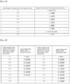
- FIG 4 is data on the refractive index of the first lens 110 for light of various wavelengths in a temperature range of low temperature (-40°C) to high temperature (90°C)
- FIG 5 is a graph showing a change in the refractive index of the first lens 110 according to a change in temperature.
- FIG 6 is data on the refraction of the second lens 120 and the third lens 130 for light of various wavelengths in a temperature range of low temperature (-40°C) to high temperature (90°C), and FIG 7 a graph showing a change in refractive index of the second lens 120 and the third lens 130 according to a change in temperature.
- the first lens 110, the second lens 120, and the third lens 130 may have different refractive index change characteristics according to a change in temperature.
- the first lens 110 has a very small refractive index that changes depending on the temperature in a temperature range of a low temperature (about -40 °C) to a high temperature (about 99 °C).
- the change (dnt_1/dt) of the refractive index according to the temperature change of the first lens 110 has a positive number as in Equation 3 and a positive slope as shown in FIG 5 .
- a change in refractive index of the second lens 120 and the third lens 130 according to temperature in a temperature range of a low temperature (about -40°C) to a high temperature (about 99°C) is relatively large compared to the first lens 110.
- the change (dnt_2/dt, dnt_3/dt) of the refractive index according to the temperature change of the first lens 110 and the second lens 120 has a negative number as in Equation 3 and a negative slope as shown in FIG 7 .
- the first lens 110 may have a refractive index greater than that of the second lens 120 and the third lens 130.
- the first lens 110 has a refractive index greater than that of the two lenses 120 and 130 to compensate for the second lens 120 and the third lens 130 having relatively large refractive index changes according to temperature change.
- the first lens 110 has a diopter value greater than that of the two lenses 120 and 130 to compensate for the second lens 120 and the third lens 130 having relatively large refractive index changes according to temperature change. Accordingly, the first lens 110 can effectively distribute the power of the optical system 1000 in a temperature range of a low temperature (about -40°C) to a high temperature (about 99°C). Accordingly, the optical system 1000 according to the embodiment may minimize or prevent deterioration of optical properties in an environment of various temperatures, and may have improved optical performance.
- the first lens 110 may be provided with a material different from that of the second lens 120 and the third lens 130, and at least one of Equations 1 to 57 may be satisfied. Accordingly, the optical system 1000 may prevent or minimize changes in optical properties according to temperature, and may have improved optical properties at various temperatures.
- the optical system 1000 according to the embodiment satisfies at least one of Equation 1 to Equation 57, it is possible to prevent or minimize changes in distortion and aberration characteristics at various temperatures, so that it has improved optical characteristics.
- the first interval may vary according to a position between the first lens 110 and the second lens 120.
- the first interval when it has the optical axis OA as the starting point and the effective area end of the sensor-side surface (the second surface S2) of the first lens 110 as the endpoint, it may change from the optical axis OA to a direction perpendicular to the optical axis OA. That is, the first interval may change from the optical axis OA toward the end of the effective diameter of the second surface S2.
- the second lens 120 and the third lens 130 may be spaced apart from each other by a second interval.
- the second interval may be a distance in the optical axis OA direction between the second lens 120 and the third lens 130.
- the second interval may vary according to a position between the second lens 120 and the third lens 130.
- the second interval when it has the optical axis OA as the starting point and the effective area end of the sensor-side surface (the fourth surface S4) of the second lens 120 as the endpoint, it may change from the optical axis OA to a direction perpendicular to the optical axis OA. That is, the second interval may change from the optical axis OA toward the end of the effective diameter of the fourth surface S4.
- optical system 1000 according to the first embodiment will be described in more detail with reference to FIGS. 8 to 31 .
- the optical system 1000 may include a first lens 110, a second lens 120, a third lens 130 and an image sensor 300 are sequentially arranged from the object side to the sensor side.
- the first to third lenses 110, 120, and 130 may be sequentially disposed along the optical axis OA of the optical system 1000.
- FIG 11 is data of the lens thickness according to the vertical height (0.2 mm interval) of the optical axis OA at room temperature (about 22°C).
- D_1 of FIG 11 is the central thickness of the first lens 110 and is the thickness (mm) of the first lens 110 on the optical axis OA.
- D_1_ET of FIG 11 means a thickness (mm) in the optical axis OA direction at the end of the effective area of the first lens 110.
- D 1 ET means a distance (mm) in the optical axis direction between the effective area end of the object-side surface (first surface S1) of the first lens 110 and the effective area end of the sensor-side surface (second surface S2) of the first lens 110.
- the thickness of the first lens 110 in the optical axis OA direction may decrease from the optical axis OA toward the end of the effective diameter of the first lens 110.
- the thickness in the optical axis OA direction of the first lens 110 may have a maximum value at the optical axis OA, and have a minimum value at the end of the effective diameter of the second surfaces S2.
- the first lens 110 may have improved aberration control characteristics by controlling the incident light.
- the second lens 120 may be made of a plastic material and may have positive (+) refractive power in the optical axis OA. Also, in the optical axis OA, the third surface S3 of the second lens 120 may have a concave shape, and the fourth surface S4 may be convex. The second lens 120 may have a meniscus shape convex from the optical axis OA toward the sensor. The third surface S3 may be an aspherical surface, and the fourth surface S4 may be an aspherical surface.
- FIG 12 is sag data according to the vertical height (0.2mm interval) of the optical axis of each of the object-side surface (third surface, S3) and the sensor-side surface (fourth surface, S4) of the second lens 120 at room temperature (about 22°C).
- FIG 13 is data of the lens thickness according to the vertical height (0.2 mm interval) of the optical axis OA at room temperature (about 22°C).
- D_2 of FIG 13 is the central thickness of the second lens 120 and is the thickness (mm) of the second lens 120 on the optical axis OA.
- D_2_ET of FIG 13 means a thickness (mm) in the optical axis OA direction at the end of the effective area of the second lens 120.
- D_2_ET means a distance (mm) in the optical axis direction between the effective area end of the object-side surface (third surface S3) of the second lens 120 and the effective area end of the sensor-side surface (fourth surface S4) of the second lens 120.
- the thickness of the second lens 120 in the optical axis OA direction may decrease from the optical axis OA toward the end of the effective diameter of the second lens 120.
- the thickness in the optical axis OA direction of the second lens 120 may have a maximum value at the optical axis OA, and have a minimum value at the end of the effective diameter of the third surfaces S3.
- the second lens 120 may prevent or minimize the change in optical properties depending on the temperature in the low to high temperature range.
- the third lens 130 may be made of a plastic material and have positive (+) refractive power in the optical axis OA. Also, in the optical axis OA, the fifth surface S5 of the third lens 130 may have a convex shape, and the sixth surface S6 may be concave. The third lens 130 may have a meniscus shape convex from the optical axis OA toward the object. The fifth surface S5 may be an aspherical surface, and the sixth surface S6 may be an aspherical surface.
- FIG 14 is sag data according to the vertical height (0.2mm interval) of the optical axis of each of the object-side surface (fifth surface, S5) and the sensor-side surface (sixth surface, S6) of the third lens 130 at room temperature (about 22°C).
- FIG 15 is data of the lens thickness according to the vertical height (0.2 mm interval) of the optical axis OA at room temperature (about 22°C).
- D_3 of FIG 15 is the central thickness of the third lens 130 and is the thickness (mm) of the third lens 130 on the optical axis OA.
- D_3_ET of FIG 15 means a thickness (mm) in the optical axis OA direction at the end of the effective area of the third lens 130.
- D_3_ET means a distance (mm) in the optical axis direction between the effective area end of the object-side surface (fifth surface S5) of the third lens 130 and the effective area end of the sensor-side surface (sixth surface S6) of the third lens 130.
- the thickness of the third lens 130 in the optical axis OA direction may increase from the optical axis OA toward the end of the effective diameter of the third lens 130.
- the thickness in the optical axis OA direction of the third lens 130 may have a maximum value at the end of the effective diameter of the fifth surfaces S5, and have a minimum value at the optical axis OA.
- the third lens 130 may prevent or minimize the change in optical properties depending on the temperature in the low to high temperature range.
- the refractive index of the first lens 110 may be different from the refractive power of the second lens 120 and the third lens 130.
- the refractive power of the first lens 110 may be about 1.1 times or more of the refractive power of the second lens 120 and the third lens 130.
- the refractive power of the first lens 110 may be greater than or equal to about 1.15 times the refractive power of the second lens 120 and the third lens 130.
- the refractive power of the first lens 110 may be about 1.2 times or more of the refractive power of the second lens 120 and the third lens 130.
- the refractive powers of the second lens 120 and the third lens 130 may be equal to each other.
- the Abbe's number of the first lens 110 may be different from that of the second lens 120 and the third lens 130.
- the difference between the Abbe's number of the first lens 110 and the Abbe's number of the second lens 120 and the third lens 130 may be 10 or less.
- the Abbe's number of the first lens 110 may be greater than the Abbe's number of the second lens 120 and the third lens 130 within a range of 10 or less.
- the values of the aspheric coefficients of each lens surface are as shown in FIG 16 .
- the interval (first interval) between the first lens 110 and the second lens 120 may be the same as that of FIG 17 below at room temperature (about 22°C)
- the first interval may decrease from the optical axis OA toward the first point L1, which is the end of the effective diameter of the second surface S2.
- the first point L1 is an approximation value of the effective radius of the second surface S2 having a smaller effective diameter among the sensor-side surface (second surface S2) of the first lens 110 and the object-side surface (third surface, S3) of the second lens 120 facing each other. That is, the first point L1 means an approximate value of 1/2 of the effective diameter value of the second surface S2 described in FIG 9 .
- the first interval may have a maximum value at the optical axis OA and a minimum value at the first point L1.
- the maximum value of the first interval may be about 1.1 times to about 3 times the minimum value.
- the maximum value of the first interval may be about 1.2 times the minimum value.
- the interval (second interval) between the second lens 120 and the third lens 130 may be the same as that of FIG 18 below at room temperature (about 22°C)
- the second interval may decrease from the optical axis OA toward the second point L2, which is the end of the effective diameter of the fourth surface S4.
- the second point L2 is an approximation value of the effective radius of the fourth surface S4 having a smaller effective diameter among the sensor-side surface (fourth surface S4) of the second lens 120 and the object-side surface (fifth surface, S5) of the third lens 130 facing each other. That is, the second point L2 means an approximate value of 1/2 of the effective diameter value of the fourth surface S4 described in FIG 9 .
- the second interval may have a maximum value at the second point L2 and a minimum value at the optical axis OA.
- the maximum value of the second interval may be about 2 times to about 4 times the minimum value.
- the maximum value of the second interval may be about 2.1 times the minimum value.
- the optical system 1000 may have improved optical properties.
- the first lens 110 and the second lens 120, and the second lens 120 and the third lens 130 are set intervals (first interval, second interval) spaced apart from each other according to the positions, respectively. Accordingly, the optical system 1000 may prevent or minimize a change in optical properties in a temperature range of low to high temperature. Accordingly, the optical system and the camera module according to the embodiment may maintain improved optical properties in various temperature ranges.
- FIG 19 is items of the above-described equations in the optical system 1000 according to the first embodiment.
- FIG 19 shows diopter values of the first to third lenses 110, 120, 130 at room temperature (about 22°C), focal lengths, total track length (TTL), BFL (Back focal length), F number, ImgH, and effective focal length (EFL) values.
- FIG 20 shows the result values of the above-described equations in the optical system 1000 according to the first embodiment.
- the optical system 1000 according to the first embodiment satisfies at least one of Equations 1 to 57.
- the optical system 1000 according to the first embodiment satisfies all of Equations 1 to 57 above.
- the optical system 1000 has an angle of view of about 60 degrees (60 ⁇ 2 degrees) in a temperature range of a low temperature (-40°C) to a high temperature (99°C), and have optical characteristics as shown in FIGS. 21 to 31 .
- FIG 21 is a graph of relative illumination for each field of the optical system according to the first embodiment
- FIG 22 is data on distortion characteristics of the optical system according to the first embodiment.
- FIGS. 21 and 22 are data obtained by measuring the optical system 1000 at room temperature (about 22°C).
- the optical system 1000 may have excellent relative illumination characteristics in the 0 field region (center region) to 1.0 field region (edge region) of the image sensor 300.
- the optical system 1000 may have the relative illumination of about 65% or more.
- the relative illumination of the 0.5 field area may be about 80% or more
- the relative illumination of the 1.0 field area may be about 65% or more.
- the relative illumination of the 1.0 field region may be about 70% or more.
- the optical system 1000 according to the first embodiment may have a barrel distortion shape in which an edge portion of an image is curved outward, and has a distortion of about 0.7408% and a TV-distortion of about -1.0052%.
- FIGS. 23 to 31 are graphs of diffraction MTF characteristics and aberration diagrams of the optical system 1000 according to temperature.
- FIGS. 23 and 24 are graphs of the diffraction MTF characteristics of the optical system 1000 in a low-temperature (-40°C) environment
- FIGS. 26 and 27 are graphs of the diffraction MTF characteristics of the optical system 1000 in a room temperature (22 °C) environment
- FIGS. 29 and 30 are graphs of diffraction MTF characteristics of the optical system 1000 in a high temperature (99°C) environment.
- FIGS. 25 , 28 and 31 are graphs of aberration diagrams of the optical system 1000 in low temperature (-40°C), room temperature (22°C) and high temperature (99°C) environments, and the graph is on the left longitudinal spherical aberration, astigmatic field curves, and distortion were measured in the right direction.
- the X-axis may indicate a focal length (mm) or distortion (%)
- the Y-axis may indicate the height of an image.
- the graph for spherical aberration is a graph for light in a wavelength band of about 920 nm, about 940 nm, and about 960 nm
- a graph for astigmatism and distortion aberration is a graph for light in a wavelength band of 940 nm.
- the optical system 1000 in the optical system 1000 according to the first embodiment, there is little or no change in MTF characteristics and aberration characteristics even when the temperature is changed in a range of a low temperature (-40°C) to a high temperature (99°C).
- the change in MTF properties at low temperature (-40°C) and high temperature (99°C) is less than 10% with respect to the change in MTF properties at room temperature (22°C).
- the optical system 1000 may maintain excellent optical properties in various temperature ranges.
- the first lens 110 is made of a material different from that of the second lens 120 and the third lens 130, for example, the first lens 110 may include a glass material, and the second lens 120 and the third lens 130 may include a plastic material. Accordingly, when the temperature increases, the refractive index of the first lens 110 may increase, and the refractive index of the second lens 120 and the third lens 130 may decrease.
- the first to third lenses 110, 120, 130 according to the first embodiment are provided with a set refractive index, shape, thickness, etc. thereby mutually compensate for a change in focal length caused by a change in refractive index that changes according to temperature. Accordingly, the optical system 1000 may prevent or minimize changes in optical properties in a temperature range of low (-40°C) to high (99°C), and maintain improved optical properties.
- optical system 1000 according to the second embodiment will be described in more detail with reference to FIGS. 32 to 55 .
- FIG 32 is a block diagram of an optical system according to the second embodiment.
- FIG 33 is a view showing a radius of curvature of the first to third lenses 110, 120, 130 according to the second embodiment, a thickness of each lens in the optical axis OA, a distance between each lens in the optical axis OA, the refractive index for light in the t-line (1013.98 nm) wavelength band, Abbe's Number, and the size of the clear aperture (CA).
- the lens data described in FIG 33 is data at room temperature (about 22°C).
- FIG 45 is a graph of relative illumination for each field of the optical system according to the second embodiment
- FIG 46 is data on distortion characteristics of the optical system according to the second embodiment.
- FIGS. 47 to 55 are graphs of diffraction MTFs and aberrations for each temperature of the optical system according to the second embodiment.
- the optical system 1000 may include a first lens 110, a second lens 120, a third lens 130 and an image sensor 300 are sequentially arranged from the object side to the sensor side.
- the first to third lenses 110, 120, and 130 may be sequentially disposed along the optical axis OA of the optical system 1000.
- the sensor-side surface (the second surface S2) of the first lens 110 may serve as an aperture stop.
- a filter 500 may be disposed between the plurality of lenses 100 and the image sensor 300, and a cover glass 400 may be disposed between the filter 500 and the image sensor 300.
- the first lens 110 of the optical system 1000 may have a glass material and may have a positive refractive power in the optical axis OA.
- the first surface S1 of the first lens 110 may have a convex shape, and the second surface S2 may be concave.
- the first lens 110 may have a meniscus shape convex from the optical axis OA toward the object.
- the first surface S1 may be a sphere, and the second surface S2 may be a sphere.
- FIG 34 is sag data according to the vertical height (0.2mm interval) of the optical axis of each of the object-side surface (first surface, S1) and the sensor-side surface (second surface, S2) of the first lens 110 at room temperature (about 22°C).
- FIG 35 is data of the lens thickness according to the vertical height (0.2 mm interval) of the optical axis OA at room temperature (about 22°C).
- D_1 of FIG 35 is the central thickness of the first lens 110 and is the thickness (mm) of the first lens 110 on the optical axis OA.
- D_1_ET of FIG 35 means a thickness (mm) in the optical axis OA direction at the end of the effective area of the first lens 110.
- D 1 ET means a distance (mm) in the optical axis direction between the effective area end of the object-side surface (first surface S1) of the first lens 110 and the effective area end of the sensor-side surface (second surface S2) of the first lens 110.
- the thickness of the first lens 110 in the optical axis OA direction may decrease from the optical axis OA toward the end of the effective diameter of the first lens 110.
- the thickness in the optical axis OA direction of the first lens 110 may have a maximum value at the optical axis OA, and have a minimum value at the end of the effective diameter of the second surfaces S2.
- the first lens 110 may have improved aberration control characteristics by controlling the incident light.
- the second lens 120 may be made of a plastic material and may have positive (+) refractive power in the optical axis OA. Also, in the optical axis OA, the third surface S3 of the second lens 120 may have a concave shape, and the fourth surface S4 may be convex. The second lens 120 may have a meniscus shape convex from the optical axis OA toward the sensor. The third surface S3 may be an aspherical surface, and the fourth surface S4 may be an aspherical surface.
- FIG 36 is sag data according to the vertical height (0.2mm interval) of the optical axis of each of the object-side surface (third surface, S3) and the sensor-side surface (fourth surface, S4) of the second lens 120 at room temperature (about 22°C).
- FIG 37 is data of the lens thickness according to the vertical height (0.2 mm interval) of the optical axis OA at room temperature (about 22°C).
- D_2 of FIG 37 is the central thickness of the second lens 120 and is the thickness (mm) of the second lens 120 on the optical axis OA.
- D_2_ET of FIG 37 means a thickness (mm) in the optical axis OA direction at the end of the effective area of the second lens 120.
- D_2_ET means a distance (mm) in the optical axis direction between the effective area end of the object-side surface (third surface S3) of the second lens 120 and the effective area end of the sensor-side surface (fourth surface S4) of the second lens 120.
- the thickness of the second lens 120 in the optical axis OA direction may decrease from the optical axis OA toward the end of the effective diameter of the second lens 120.
- the thickness in the optical axis OA direction of the second lens 120 may have a maximum value at the optical axis OA, and have a minimum value at the end of the effective diameter of the third surfaces S3.
- the second lens 120 may prevent or minimize the change in optical properties depending on the temperature in the low to high temperature range.
- the third lens 130 may be made of a plastic material and have positive (+) refractive power in the optical axis OA. Also, in the optical axis OA, the fifth surface S5 of the third lens 130 may have a convex shape, and the sixth surface S6 may be concave. The third lens 130 may have a meniscus shape convex from the optical axis OA toward the object. The fifth surface S5 may be an aspherical surface, and the sixth surface S6 may be an aspherical surface.
- FIG 38 is sag data according to the vertical height (0.2mm interval) of the optical axis of each of the object-side surface (fifth surface, S5) and the sensor-side surface (sixth surface, S6) of the third lens 130 at room temperature (about 22°C).
- FIG 39 is data of the lens thickness according to the vertical height (0.2 mm interval) of the optical axis OA at room temperature (about 22°C).
- D_3 of FIG 39 is the central thickness of the third lens 130 and is the thickness (mm) of the third lens 130 on the optical axis OA.
- D_3_ET of FIG 39 means a thickness (mm) in the optical axis OA direction at the end of the effective area of the third lens 130.
- D_3_ET means a distance (mm) in the optical axis direction between the effective area end of the object-side surface (fifth surface S5) of the third lens 130 and the effective area end of the sensor-side surface (sixth surface S6) of the third lens 130.
- the thickness of the third lens 130 in the optical axis OA direction may increase from the optical axis OA toward the end of the effective diameter of the third lens 130.
- the thickness in the optical axis OA direction of the third lens 130 may have a maximum value at the end of the effective diameter of the fifth surfaces S5, and have a minimum value at the optical axis OA.
- the third lens 130 may prevent or minimize the change in optical properties depending on the temperature in the low to high temperature range.
- the refractive index of the first lens 110 may be different from the refractive power of the second lens 120 and the third lens 130.
- the refractive power of the first lens 110 may be about 1.1 times or more of the refractive power of the second lens 120 and the third lens 130.
- the refractive power of the first lens 110 may be greater than or equal to about 1.15 times the refractive power of the second lens 120 and the third lens 130.
- the refractive power of the first lens 110 may be about 1.2 times or more of the refractive power of the second lens 120 and the third lens 130.
- the refractive powers of the second lens 120 and the third lens 130 may be equal to each other.
- the Abbe's number of the first lens 110 may be different from that of the second lens 120 and the third lens 130.
- the difference between the Abbe's number of the first lens 110 and the Abbe's number of the second lens 120 and the third lens 130 may be 10 or less.
- the Abbe's number of the first lens 110 may be greater than the Abbe's number of the second lens 120 and the third lens 130 within a range of 10 or less.
- the values of the aspheric coefficients of each lens surface are as shown in FIG 40 .
- the interval (first interval) between the first lens 110 and the second lens 120 may be the same as that of FIG 41 below at room temperature (about 22°C)
- the first interval may decrease from the optical axis OA toward the first point L1, which is the end of the effective diameter of the second surface S2.
- the first point L1 is an approximation value of the effective radius of the second surface S2 having a smaller effective diameter among the sensor-side surface (second surface S2) of the first lens 110 and the object-side surface (third surface, S3) of the second lens 120 facing each other. That is, the first point L1 means an approximate value of 1/2 of the effective diameter value of the second surface S2 described in FIG 33 .
- the first interval may have a maximum value at the optical axis OA and a minimum value at the first point L1.
- the maximum value of the first interval may be about 1.1 times to about 3 times the minimum value.
- the maximum value of the first interval may be about 1.2 times the minimum value.
- the interval (second interval) between the second lens 120 and the third lens 130 may be the same as that of FIG 42 below at room temperature (about 22°C)
- the second interval may decrease from the optical axis OA toward the second point L2, which is the end of the effective diameter of the fourth surface S4.
- the second point L2 is an approximation value of the effective radius of the fourth surface S4 having a smaller effective diameter among the sensor-side surface (fourth surface S4) of the second lens 120 and the object-side surface (fifth surface, S5) of the third lens 130 facing each other. That is, the second point L2 means an approximate value of 1/2 of the effective diameter value of the fourth surface S4 described in FIG 33 .
- the second interval may have a maximum value at the second point L2 and a minimum value at the optical axis OA.
- the maximum value of the second interval may be about 2 times to about 4 times the minimum value.
- the maximum value of the second interval may be about 2.1 times the minimum value.
- the optical system 1000 may have improved optical properties.
- the first lens 110 and the second lens 120, and the second lens 120 and the third lens 130 are set intervals (first interval, second interval) spaced apart from each other according to the positions, respectively. Accordingly, the optical system 1000 may prevent or minimize a change in optical properties in a temperature range of low to high temperature. Accordingly, the optical system and the camera module according to the embodiment may maintain improved optical properties in various temperature ranges.
- FIG 43 is items of the above-described equations in the optical system 1000 according to the second embodiment.
- FIG 19 shows diopter values of the first to third lenses 110, 120, 130 at room temperature (about 22°C), focal lengths, total track length (TTL), BFL (Back focal length), F number, ImgH, and effective focal length (EFL) values.
- FIG 44 shows the result values of the above-described equations in the optical system 1000 according to the second embodiment.
- the optical system 1000 according to the second embodiment satisfies at least one of Equations 1 to 57.
- the optical system 1000 according to the second embodiment satisfies all of Equations 1 to 57 above.
- the optical system 1000 according to the second embodiment has an angle of view of about 60 degrees (60 ⁇ 2 degrees) in a temperature range of a low temperature (-40°C) to a high temperature (99°C), and have optical characteristics as shown in FIGS. 45 to 55 .
- FIG 45 is a graph of relative illumination for each field of the optical system according to the second embodiment
- FIG 46 is data on distortion characteristics of the optical system according to the second embodiment.
- FIGS. 45 and 46 are data obtained by measuring the optical system 1000 at room temperature (about 22°C).
- the optical system 1000 may have excellent relative illumination characteristics in the 0 field region (center region) to 1.0 field region (edge region) of the image sensor 300.
- the optical system 1000 may have the relative illumination of about 65% or more.
- the relative illumination of the 0.5 field area may be about 80% or more
- the relative illumination of the 1.0 field area may be about 65% or more.
- the relative illumination of the 1.0 field region may be about 70% or more.
- the optical system 1000 according to the second embodiment may have a barrel distortion shape in which an edge portion of an image is curved outward, and has a distortion of about 0.4630% and a TV-distortion of about -0.9464%.
- FIGS. 47 to 55 are graphs of diffraction MTF characteristics and aberration diagrams of the optical system 1000 according to temperature.
- FIGS. 47 and 48 are graphs of the diffraction MTF characteristics of the optical system 1000 in a low-temperature (-40°C) environment
- FIGS. 50 and 51 are graphs of the diffraction MTF characteristics of the optical system 1000 in a room temperature (22 °C) environment
- FIGS. 53 and 54 are graphs of diffraction MTF characteristics of the optical system 1000 in a high temperature (99°C) environment.
- FIGS. 49 , 52 and 55 are graphs of aberration diagrams of the optical system 1000 in low temperature (-40°C), room temperature (22°C) and high temperature (99°C) environments, and the graph is on the left longitudinal spherical aberration, astigmatic field curves, and distortion were measured in the right direction.
- the X-axis may indicate a focal length (mm) or distortion (%)
- the Y-axis may indicate the height of an image.
- the graph for spherical aberration is a graph for light in a wavelength band of about 920 nm, about 940 nm, and about 960 nm
- a graph for astigmatism and distortion aberration is a graph for light in a wavelength band of 940 nm.
- the optical system 1000 in the optical system 1000 according to the second embodiment, there is little or no change in MTF characteristics and aberration characteristics even when the temperature is changed in a range of a low temperature (-40°C) to a high temperature (99°C).
- the change in MTF properties at low temperature (-40°C) and high temperature (99°C) is less than 10% with respect to the change in MTF properties at room temperature (22°C).
- the optical system 1000 may maintain excellent optical properties in various temperature ranges.
- the first lens 110 is made of a material different from that of the second lens 120 and the third lens 130, for example, the first lens 110 may include a glass material, and the second lens 120 and the third lens 130 may include a plastic material. Accordingly, when the temperature increases, the refractive index of the first lens 110 may increase, and the refractive index of the second lens 120 and the third lens 130 may decrease.
- the first to third lenses 110, 120, 130 according to the second embodiment are provided with a set refractive index, shape, thickness, etc. thereby mutually compensate for a change in focal length caused by a change in refractive index that changes according to temperature. Accordingly, the optical system 1000 may prevent or minimize changes in optical properties in a temperature range of low (-40°C) to high (99°C), and maintain improved optical properties.
- optical system 1000 according to the third embodiment will be described in more detail with reference to FIGS. 56 to 77 .
- the optical system 1000 may include a first lens 110, a second lens 120, a third lens 130 and an image sensor 300 are sequentially arranged from the object side to the sensor side.
- the first to third lenses 110, 120, and 130 may be sequentially disposed along the optical axis OA of the optical system 1000.
- the aperture 600 may be disposed between the sensor-side surface (second surface S2) of the first lens 110 and the object-side surface (third surface S3) of the second lens 120.
- the aperture 600 may be disposed to be spaced apart from the sensor side surface (the second surface S2) of the first lens 110 at between the sensor-side surface (second surface S2) of the first lens 110 and the object-side surface (third surface S3) of the second lens 120.
- the aperture 600 may be disposed to be spaced apart from the sensor-side surface (the second surface S2) of the first lens 110 as shown in Equations 52 and 53 above.
- the sensor-side surface (the second surface S2) of the first lens 110 may serve as an aperture stop.
- a filter 500 may be disposed between the plurality of lenses 100 and the image sensor 300, and a cover glass 400 may be disposed between the filter 500 and the image sensor 300.
- FIG 57 is a view showing a radius of curvature of the first to third lenses 110, 120, 130 according to the third embodiment, a thickness of each lens in the optical axis OA, a distance between each lens in the optical axis OA, the refractive index for light in the t-line (1013.98 nm) wavelength band, Abbe's Number, and the size of the clear aperture (CA).
- the lens data described in FIG 57 is data at room temperature (about 22°C)
- the first lens 110 of the optical system 1000 may have a glass material and may have a positive refractive power in the optical axis OA.
- the first surface S1 of the first lens 110 may have a convex shape, and the second surface S2 may be concave.
- the first lens 110 may have a meniscus shape convex from the optical axis OA toward the object.
- the first surface S1 may be a sphere, and the second surface S2 may be a sphere.
- FIG 58 is sag data according to the vertical height (0.2mm interval) of the optical axis of each of the object-side surface (first surface, S1) and the sensor-side surface (second surface, S2) of the first lens 110 at room temperature (about 22°C).
- FIG 59 is data of the lens thickness according to the vertical height (0.2 mm interval) of the optical axis OA at room temperature (about 22°C).
- D_1 of FIG 59 is the central thickness of the first lens 110 and is the thickness (mm) of the first lens 110 on the optical axis OA.
- D_1_ET of FIG 59 means a thickness (mm) in the optical axis OA direction at the end of the effective area of the first lens 110.
- D_1_ET means a distance (mm) in the optical axis direction between the effective area end of the object-side surface (first surface S1) of the first lens 110 and the effective area end of the sensor-side surface (second surface S2) of the first lens 110.
- the thickness of the first lens 110 in the optical axis OA direction may increase from the optical axis OA toward the end of the effective diameter of the first lens 110.
- the first lens 110 may have improved aberration control characteristics by controlling the incident light.
- the second lens 120 may be made of a plastic material and may have positive (+) refractive power in the optical axis OA. Also, in the optical axis OA, the third surface S3 of the second lens 120 may have a concave shape, and the fourth surface S4 may be convex. The second lens 120 may have a meniscus shape convex from the optical axis OA toward the sensor. The third surface S3 may be an aspherical surface, and the fourth surface S4 may be an aspherical surface.
- FIG 60 is sag data according to the vertical height (0.2mm interval) of the optical axis of each of the object-side surface (third surface, S3) and the sensor-side surface (fourth surface, S4) of the second lens 120 at room temperature (about 22°C).
- FIG 61 is data of the lens thickness according to the vertical height (0.2 mm interval) of the optical axis OA at room temperature (about 22°C).
- D_2 of FIG 61 is the central thickness of the second lens 120 and is the thickness (mm) of the second lens 120 on the optical axis OA.
- D_2_ET of FIG 61 means a thickness (mm) in the optical axis OA direction at the end of the effective area of the second lens 120.
- D_2_ET means a distance (mm) in the optical axis direction between the effective area end of the object-side surface (third surface S3) of the second lens 120 and the effective area end of the sensor-side surface (fourth surface S4) of the second lens 120.
- the thickness of the second lens 120 in the optical axis OA direction may decrease from the optical axis OA toward the end of the effective diameter of the second lens 120.
- the thickness in the optical axis OA direction of the second lens 120 may have a maximum value at the optical axis OA, and have a minimum value at the end of the effective diameter of the third surfaces S3.
- the second lens 120 may prevent or minimize the change in optical properties depending on the temperature in the low to high temperature range.
- the third lens 130 may be made of a plastic material and have positive (+) refractive power in the optical axis OA. Also, in the optical axis OA, the fifth surface S5 of the third lens 130 may have a convex shape, and the sixth surface S6 may be concave. The third lens 130 may have a meniscus shape convex from the optical axis OA toward the object. The fifth surface S5 may be an aspherical surface, and the sixth surface S6 may be an aspherical surface.
- FIG 62 is sag data according to the vertical height (0.2mm interval) of the optical axis of each of the object-side surface (fifth surface, S5) and the sensor-side surface (sixth surface, S6) of the third lens 130 at room temperature (about 22°C).
- FIG 63 is data of the lens thickness according to the vertical height (0.2 mm interval) of the optical axis OA at room temperature (about 22°C).
- D_3 of FIG 63 is the central thickness of the third lens 130 and is the thickness (mm) of the third lens 130 on the optical axis OA.
- D_3_ET of FIG 63 means a thickness (mm) in the optical axis OA direction at the end of the effective area of the third lens 130.
- D_3_ET means a distance (mm) in the optical axis direction between the effective area end of the object-side surface (fifth surface S5) of the third lens 130 and the effective area end of the sensor-side surface (sixth surface S6) of the third lens 130.
- the thickness of the third lens 130 in the optical axis OA direction may increase from the optical axis OA toward the end of the effective diameter of the third lens 130.
- the thickness in the optical axis OA direction of the third lens 130 may have a maximum value at the end of the effective diameter of the fifth surfaces S5, and have a minimum value at the optical axis OA.
- the third lens 130 may prevent or minimize the change in optical properties depending on the temperature in the low to high temperature range.
- the refractive index of the first lens 110 may be different from the refractive power of the second lens 120 and the third lens 130.
- the refractive power of the first lens 110 may be about 1.2 times or more of the refractive power of the second lens 120 and the third lens 130.
- the refractive power of the first lens 110 may be greater than or equal to about 1.5 times the refractive power of the second lens 120 and the third lens 130.
- the refractive power of the first lens 110 may be about 1.8 times or more of the refractive power of the second lens 120 and the third lens 130.
- the refractive index of the second lens 120 may be different from the refractive power of the third lens 130.
- the refractive power of the second lens 120 may be about 10 times or more of the refractive power of the third lens 130.
- the refractive power of the second lens 120 may be about 15 times or more of the refractive power of the third lens 130.
- the refractive power of the second lens 120 may be about 30 times or more of the refractive power of the third lens 130.
- the Abbe's number of the first lens 110 may be different from that of the second lens 120 and the third lens 130.
- the difference between the Abbe's number of the first lens 110 and the Abbe's number of the second lens 120 and the third lens 130 may be 10 or less.
- the Abbe's number of the first lens 110 may be greater than the Abbe's number of the second lens 120 and the third lens 130 within a range of 10 or less.
- the values of the aspheric coefficients of each lens surface are as shown in FIG 64 .
- the interval (first interval) between the first lens 110 and the second lens 120 may be the same as that of FIG 65 below at room temperature (about 22°C).
- the interval (second interval) between the second lens 120 and the third lens 130 may be the same as that of FIG 66 below at room temperature (about 22°C).
- the first interval may decrease from the optical axis OA toward the first point L1, which is the end of the effective diameter of the second surface S2.
- the first point L1 is an approximation value of the effective radius of the second surface S2 having a smaller effective diameter among the sensor-side surface (second surface S2) of the first lens 110 and the object-side surface (third surface, S3) of the second lens 120 facing each other. That is, the first point L1 means an approximate value of 1/2 of the effective diameter value of the second surface S2 described in FIG 57 .
- the first interval may have a maximum value at the optical axis OA and a minimum value at the first point L1.
- the maximum value of the first interval may be about 1.1 times to about 3 times the minimum value.
- the maximum value of the first interval may be about 1.2 times the minimum value.
- the second interval may decrease from the optical axis OA toward the second point L2, which is the end of the effective diameter of the fourth surface S4.
- the second point L2 is an approximation value of the effective radius of the fourth surface S4 having a smaller effective diameter among the sensor-side surface (fourth surface S4) of the second lens 120 and the object-side surface (fifth surface, S5) of the third lens 130 facing each other. That is, the second point L2 means an approximate value of 1/2 of the effective diameter value of the fourth surface S4 described in FIG 57 .
- the second interval may have a maximum value at the second point L2 and a minimum value at the optical axis OA.
- the maximum value of the second interval may be about 2 times to about 4 times the minimum value.
- the maximum value of the second interval may be about 2.6 times the minimum value.
- the optical system 1000 may have improved optical properties.
- the first lens 110 and the second lens 120, and the second lens 120 and the third lens 130 are set intervals (first interval, second interval) spaced apart from each other according to the positions, respectively. Accordingly, the optical system 1000 may prevent or minimize a change in optical properties in a temperature range of low to high temperature. Accordingly, the optical system and the camera module according to the embodiment may maintain improved optical properties in various temperature ranges.
- FIG 67 is a graph of relative illumination for each field of the optical system according to the third embodiment
- FIG 68 is data on distortion characteristics of the optical system according to the third embodiment.
- FIGS. 67 and 68 are data obtained by measuring the optical system 1000 at room temperature (about 22°C).
- the optical system 1000 may have excellent relative illumination characteristics in the 0 field region (center region) to 1.0 field region (edge region) of the image sensor 300.
- the optical system 1000 may have the relative illumination of about 70% or more.
- the relative illumination of the 0.5 field area may be about 80% or more
- the relative illumination of the 1.0 field area may be about 70% or more.
- the optical system 1000 according to the third embodiment may have a barrel distortion shape in which an edge portion of an image is curved outward, and has a distortion of about 1.1179% and a TV-distortion of about -0.7453%.
- FIGS. 69 to 77 are graphs of diffraction MTF characteristics and aberration diagrams of the optical system 1000 according to temperature.
- FIGS. 69 and 70 are graphs of the diffraction MTF characteristics of the optical system 1000 in a low-temperature (-40°C) environment
- FIGS. 72 and 73 are graphs of the diffraction MTF characteristics of the optical system 1000 in a room temperature (22 °C) environment
- FIGS. 75 and 76 are graphs of diffraction MTF characteristics of the optical system 1000 in a high temperature (99°C) environment.
- FIGS. 71 , 74 and 77 are graphs of aberration diagrams of the optical system 1000 in low temperature (-40°C), room temperature (22°C) and high temperature (99°C) environments, and the graph is on the left longitudinal spherical aberration, astigmatic field curves, and distortion were measured in the right direction.
- FIGS. 71 , 74 and 77 the X-axis may indicate a focal length (mm) or distortion (%), and the Y-axis may indicate the height of an image.
- the graph for spherical aberration is a graph for light in a wavelength band of about 920 nm, about 940 nm, and about 960 nm
- a graph for astigmatism and distortion aberration is a graph for light in a wavelength band of 940 nm.
- the optical system 1000 in the optical system 1000 according to the third embodiment, there is little or no change in MTF characteristics and aberration characteristics even when the temperature is changed in a range of a low temperature (-40°C) to a high temperature (99°C).
- the change in MTF properties at low temperature (-40°C) and high temperature (99°C) is less than 10% with respect to the change in MTF properties at room temperature (22°C).
- the optical system 1000 may maintain excellent optical properties in various temperature ranges.
- the first lens 110 is made of a material different from that of the second lens 120 and the third lens 130, for example, the first lens 110 may include a glass material, and the second lens 120 and the third lens 130 may include a plastic material. Accordingly, when the temperature increases, the refractive index of the first lens 110 may increase, and the refractive index of the second lens 120 and the third lens 130 may decrease.
- the first to third lenses 110, 120, 130 according to the third embodiment are provided with a set refractive index, shape, thickness, etc. thereby mutually compensate for a change in focal length caused by a change in refractive index that changes according to temperature. Accordingly, the optical system 1000 may prevent or minimize changes in optical properties in a temperature range of low (-40°C) to high (99°C), and maintain improved optical properties.
- optical system 1000 according to the fourth embodiment will be described in more detail with reference to FIGS. 78 to 99 .
- the optical system 1000 may include a first lens 110, a second lens 120, a third lens 130 and an image sensor 300 are sequentially arranged from the object side to the sensor side.
- the first to third lenses 110, 120, and 130 may be sequentially disposed along the optical axis OA of the optical system 1000.
- the aperture 600 may be disposed between the sensor-side surface (second surface S2) of the first lens 110 and the object-side surface (third surface S3) of the second lens 120.
- the aperture 600 may be disposed to be spaced apart from the sensor side surface (the second surface S2) of the first lens 110 at between the sensor-side surface (second surface S2) of the first lens 110 and the object-side surface (third surface S3) of the second lens 120.
- the aperture 600 may be disposed to be spaced apart from the sensor-side surface (the second surface S2) of the first lens 110 as shown in Equations 52 and 53 above.
- a filter 500 may be disposed between the plurality of lenses 100 and the image sensor 300, and a cover glass 400 may be disposed between the filter 500 and the image sensor 300.
- FIG 79 is a view showing a radius of curvature of the first to third lenses 110, 120, 130 according to the third embodiment, a thickness of each lens in the optical axis OA, a distance between each lens in the optical axis OA, the refractive index for light in the t-line (1013.98 nm) wavelength band, Abbe's Number, and the size of the clear aperture (CA).
- the lens data described in FIG 79 is data at room temperature (about 22°C)
- the first lens 110 of the optical system 1000 may have a glass material and may have a positive refractive power in the optical axis OA.
- the first surface S1 of the first lens 110 may have a convex shape, and the second surface S2 may be concave.
- the first lens 110 may have a meniscus shape convex from the optical axis OA toward the object.
- the first surface S1 may be a sphere, and the second surface S2 may be a sphere.
- FIG 80 is sag data according to the vertical height (0.2mm interval) of the optical axis of each of the object-side surface (first surface, S1) and the sensor-side surface (second surface, S2) of the first lens 110 at room temperature (about 22°C).
- FIG 81 is data of the lens thickness according to the vertical height (0.2 mm interval) of the optical axis OA at room temperature (about 22°C).
- D_1 of FIG 81 is the central thickness of the first lens 110 and is the thickness (mm) of the first lens 110 on the optical axis OA.
- D_1_ET of FIG 81 means a thickness (mm) in the optical axis OA direction at the end of the effective area of the first lens 110.
- D_1_ET means a distance (mm) in the optical axis direction between the effective area end of the object-side surface (first surface S1) of the first lens 110 and the effective area end of the sensor-side surface (second surface S2) of the first lens 110.
- the thickness of the first lens 110 in the optical axis OA direction may increase from the optical axis OA toward the end of the effective diameter of the first lens 110.
- the first lens 110 may have improved aberration control characteristics by controlling the incident light.
- the second lens 120 may be made of a plastic material and may have positive (+) refractive power in the optical axis OA. Also, in the optical axis OA, the third surface S3 of the second lens 120 may have a concave shape, and the fourth surface S4 may be convex. The second lens 120 may have a meniscus shape convex from the optical axis OA toward the sensor. The third surface S3 may be an aspherical surface, and the fourth surface S4 may be an aspherical surface.
- FIG 82 is sag data according to the vertical height (0.2mm interval) of the optical axis of each of the object-side surface (third surface, S3) and the sensor-side surface (fourth surface, S4) of the second lens 120 at room temperature (about 22°C).
- FIG 83 is data of the lens thickness according to the vertical height (0.2 mm interval) of the optical axis OA at room temperature (about 22°C).
- D_2 of FIG 83 is the central thickness of the second lens 120 and is the thickness (mm) of the second lens 120 on the optical axis OA.
- D_2_ET of FIG 83 means a thickness (mm) in the optical axis OA direction at the end of the effective area of the second lens 120.
- D_2_ET means a distance (mm) in the optical axis direction between the effective area end of the object-side surface (third surface S3) of the second lens 120 and the effective area end of the sensor-side surface (fourth surface S4) of the second lens 120.
- the thickness of the second lens 120 in the optical axis OA direction may decrease from the optical axis OA toward the end of the effective diameter of the second lens 120.
- the thickness in the optical axis OA direction of the second lens 120 may have a maximum value at the optical axis OA.
- the second lens 120 may prevent or minimize the change in optical properties depending on the temperature in the low to high temperature range.
- the third lens 130 may be made of a plastic material and have positive (+) refractive power in the optical axis OA. Also, in the optical axis OA, the fifth surface S5 of the third lens 130 may have a convex shape, and the sixth surface S6 may be concave. The third lens 130 may have a meniscus shape convex from the optical axis OA toward the object. The fifth surface S5 may be an aspherical surface, and the sixth surface S6 may be an aspherical surface.
- FIG 84 is sag data according to the vertical height (0.2mm interval) of the optical axis of each of the object-side surface (fifth surface, S5) and the sensor-side surface (sixth surface, S6) of the third lens 130 at room temperature (about 22°C).
- FIG 85 is data of the lens thickness according to the vertical height (0.2 mm interval) of the optical axis OA at room temperature (about 22°C).
- D_3 of FIG 85 is the central thickness of the third lens 130 and is the thickness (mm) of the third lens 130 on the optical axis OA.
- D_3_ET of FIG 85 means a thickness (mm) in the optical axis OA direction at the end of the effective area of the third lens 130.
- D_3_ET means a distance (mm) in the optical axis direction between the effective area end of the object-side surface (fifth surface S5) of the third lens 130 and the effective area end of the sensor-side surface (sixth surface S6) of the third lens 130.
- the thickness of the third lens 130 in the optical axis OA direction may increase from the optical axis OA toward the end of the effective diameter of the third lens 130.
- the third lens 130 may prevent or minimize the change in optical properties depending on the temperature in the low to high temperature range.
- the refractive index of the first lens 110 may be different from the refractive power of the second lens 120 and the third lens 130.
- the refractive power of the first lens 110 may be about 2 times or more of the refractive power of the second lens 120 and the third lens 130.
- the refractive power of the first lens 110 may be greater than or equal to about 2.5 times the refractive power of the second lens 120 and the third lens 130.
- the refractive power of the first lens 110 may be about 3 times or more of the refractive power of the second lens 120 and the third lens 130.
- the refractive index of the second lens 120 may be different from the refractive power of the third lens 130.
- the refractive power of the second lens 120 may be about 1.2 times or more of the refractive power of the third lens 130.
- the refractive power of the second lens 120 may be about 1.5 times or more of the refractive power of the third lens 130.
- the refractive power of the second lens 120 may be about 1.7 times or more of the refractive power of the third lens 130.
- the Abbe's number of the first lens 110 may be different from that of the second lens 120 and the third lens 130.
- the difference between the Abbe's number of the first lens 110 and the Abbe's number of the second lens 120 and the third lens 130 may be 10 or less.
- the Abbe's number of the first lens 110 may be greater than the Abbe's number of the second lens 120 and the third lens 130 within a range of 10 or less.
- the values of the aspheric coefficients of each lens surface are as shown in FIG 86 .
- the interval (first interval) between the first lens 110 and the second lens 120 may be the same as that of FIG 87 below at room temperature (about 22°C).
- the interval (second interval) between the second lens 120 and the third lens 130 may be the same as that of FIG 88 below at room temperature (about 22°C).
- the first interval may decrease from the optical axis OA toward the first point L1, which is the end of the effective diameter of the second surface S2.
- the first point L1 is an approximation value of the effective radius of the second surface S2 having a smaller effective diameter among the sensor-side surface (second surface S2) of the first lens 110 and the object-side surface (third surface, S3) of the second lens 120 facing each other. That is, the first point L1 means an approximate value of 1/2 of the effective diameter value of the second surface S2 described in FIG 57 .
- the first interval may have a maximum value at the optical axis OA and a minimum value at the first point L1.
- the maximum value of the first interval may be about 1.1 times to about 3 times the minimum value.
- the maximum value of the first interval may be about 1.2 times the minimum value.
- the second interval may decrease from the optical axis OA toward the second point L2, which is the end of the effective diameter of the fourth surface S4.
- the second point L2 is an approximation value of the effective radius of the fourth surface S4 having a smaller effective diameter among the sensor-side surface (fourth surface S4) of the second lens 120 and the object-side surface (fifth surface, S5) of the third lens 130 facing each other. That is, the second point L2 means an approximate value of 1/2 of the effective diameter value of the fourth surface S4 described in FIG 57 .
- the second interval may have a maximum value at the second point L2 and a minimum value at the optical axis OA.
- the maximum value of the second interval may be about 2 times to about 4 times the minimum value.
- the maximum value of the second interval may be about 2.6 times the minimum value.
- the optical system 1000 may have improved optical properties.
- the first lens 110 and the second lens 120, and the second lens 120 and the third lens 130 are set intervals (first interval, second interval) spaced apart from each other according to the positions, respectively. Accordingly, the optical system 1000 may prevent or minimize a change in optical properties in a temperature range of low to high temperature. Accordingly, the optical system and the camera module according to the embodiment may maintain improved optical properties in various temperature ranges.
- FIG 89 is a graph of relative illumination for each field of the optical system according to the fourth embodiment
- FIG 68 is data on distortion characteristics of the optical system according to the fourth embodiment.
- FIGS. 67 and 68 are data obtained by measuring the optical system 1000 at room temperature (about 22°C).
- the optical system 1000 may have excellent relative illumination characteristics in the 0 field region (center region) to 1.0 field region (edge region) of the image sensor 300.
- the optical system 1000 may have the relative illumination of about 70% or more.
- the relative illumination of the 0.5 field area may be about 80% or more
- the relative illumination of the 1.0 field area may be about 70% or more.
- the optical system 1000 may have a barrel distortion shape in which an edge portion of an image is curved outward, and has a distortion of about 0.9824% and a TV-distortion of about -0.7338%.
- FIGS. 91 to 99 are graphs of diffraction MTF characteristics and aberration diagrams of the optical system 1000 according to temperature.
- FIGS. 91 and 92 are graphs of the diffraction MTF characteristics of the optical system 1000 in a low-temperature (-40°C) environment
- FIGS. 94 and 95 are graphs of the diffraction MTF characteristics of the optical system 1000 in a room temperature (22 °C) environment
- FIGS. 97 and 98 are graphs of diffraction MTF characteristics of the optical system 1000 in a high temperature (99°C) environment.
- FIGS. 93 , 96 and 99 are graphs of aberration diagrams of the optical system 1000 in low temperature (-40°C), room temperature (22°C) and high temperature (99°C) environments, and the graph is on the left longitudinal spherical aberration, astigmatic field curves, and distortion were measured in the right direction.
- FIGS. 93 , 96 and 99 the X-axis may indicate a focal length (mm) or distortion (%), and the Y-axis may indicate the height of an image.
- the graph for spherical aberration is a graph for light in a wavelength band of about 920 nm, about 940 nm, and about 960 nm
- a graph for astigmatism and distortion aberration is a graph for light in a wavelength band of 940 nm.
- the optical system 1000 in the optical system 1000 according to the fourth embodiment, there is little or no change in MTF characteristics and aberration characteristics even when the temperature is changed in a range of a low temperature (-40°C) to a high temperature (99°C).
- the change in MTF properties at low temperature (-40°C) and high temperature (99°C) is less than 10% with respect to the change in MTF properties at room temperature (22°C).
- the optical system 1000 may maintain excellent optical properties in various temperature ranges.
- the first lens 110 is made of a material different from that of the second lens 120 and the third lens 130, for example, the first lens 110 may include a glass material, and the second lens 120 and the third lens 130 may include a plastic material. Accordingly, when the temperature increases, the refractive index of the first lens 110 may increase, and the refractive index of the second lens 120 and the third lens 130 may decrease.
- the first to third lenses 110, 120, 130 according to the fourth embodiment are provided with a set refractive index, shape, thickness, etc. thereby mutually compensate for a change in focal length caused by a change in refractive index that changes according to temperature. Accordingly, the optical system 1000 may prevent or minimize changes in optical properties in a temperature range of low (-40°C) to high (99°C), and maintain improved optical properties.
- optical system 1000 according to the fifth embodiment will be described in more detail with reference to FIGS. 100 to 121 .
- the optical system 1000 may include a first lens 110, a second lens 120, a third lens 130 and an image sensor 300 are sequentially arranged from the object side to the sensor side.
- the first to third lenses 110, 120, and 130 may be sequentially disposed along the optical axis OA of the optical system 1000.
- the aperture 600 may be disposed between the sensor-side surface (second surface S2) of the first lens 110 and the object-side surface (third surface S3) of the second lens 120.
- the aperture 600 may be disposed to be spaced apart from the sensor side surface (the second surface S2) of the first lens 110 at between the sensor-side surface (second surface S2) of the first lens 110 and the object-side surface (third surface S3) of the second lens 120.
- the aperture 600 may be disposed to be spaced apart from the sensor-side surface (the second surface S2) of the first lens 110 as shown in Equations 52 and 53 above.
- a filter 500 may be disposed between the plurality of lenses 100 and the image sensor 300, and a cover glass 400 may be disposed between the filter 500 and the image sensor 300.
- FIG 101 is a view showing a radius of curvature of the first to third lenses 110, 120, 130 according to the third embodiment, a thickness of each lens in the optical axis OA, a distance between each lens in the optical axis OA, the refractive index for light in the t-line (1013.98 nm) wavelength band, Abbe's Number, and the size of the clear aperture (CA).
- the lens data described in FIG 101 is data at room temperature (about 22°C)
- the first lens 110 of the optical system 1000 may have a glass material and may have a positive refractive power in the optical axis OA.
- the first surface S1 of the first lens 110 may have a convex shape, and the second surface S2 may be concave.
- the first lens 110 may have a meniscus shape convex from the optical axis OA toward the object.
- the first surface S1 may be a sphere, and the second surface S2 may be a sphere.
- FIG 102 is sag data according to the vertical height (0.2mm interval) of the optical axis of each of the object-side surface (first surface, S1) and the sensor-side surface (second surface, S2) of the first lens 110 at room temperature (about 22°C).
- FIG 103 is data of the lens thickness according to the vertical height (0.2 mm interval) of the optical axis OA at room temperature (about 22°C).
- D_1 of FIG 103 is the central thickness of the first lens 110 and is the thickness (mm) of the first lens 110 on the optical axis OA.
- D_1_ET of FIG 103 means a thickness (mm) in the optical axis OA direction at the end of the effective area of the first lens 110.
- D_1_ET means a distance (mm) in the optical axis direction between the effective area end of the object-side surface (first surface S1) of the first lens 110 and the effective area end of the sensor-side surface (second surface S2) of the first lens 110.
- the thickness of the first lens 110 in the optical axis OA direction may increase from the optical axis OA toward the end of the effective diameter of the first lens 110.
- the first lens 110 may have improved aberration control characteristics by controlling the incident light.
- the second lens 120 may be made of a plastic material and may have positive (+) refractive power in the optical axis OA. Also, in the optical axis OA, the third surface S3 of the second lens 120 may have a concave shape, and the fourth surface S4 may be convex. The second lens 120 may have a meniscus shape convex from the optical axis OA toward the sensor. The third surface S3 may be an aspherical surface, and the fourth surface S4 may be an aspherical surface.
- FIG 104 is sag data according to the vertical height (0.2mm interval) of the optical axis of each of the object-side surface (third surface, S3) and the sensor-side surface (fourth surface, S4) of the second lens 120 at room temperature (about 22°C).
- FIG 105 is data of the lens thickness according to the vertical height (0.2 mm interval) of the optical axis OA at room temperature (about 22°C).
- D_2 of FIG 105 is the central thickness of the second lens 120 and is the thickness (mm) of the second lens 120 on the optical axis OA.
- D_2_ET of FIG 105 means a thickness (mm) in the optical axis OA direction at the end of the effective area of the second lens 120.
- D_2_ET means a distance (mm) in the optical axis direction between the effective area end of the object-side surface (third surface S3) of the second lens 120 and the effective area end of the sensor-side surface (fourth surface S4) of the second lens 120.
- the thickness of the second lens 120 in the optical axis OA direction may decrease from the optical axis OA toward the end of the effective diameter of the second lens 120.
- the thickness in the optical axis OA direction of the second lens 120 may have a maximum value at the optical axis OA.
- the second lens 120 may prevent or minimize the change in optical properties depending on the temperature in the low to high temperature range.
- the third lens 130 may be made of a plastic material and have positive (+) refractive power in the optical axis OA. Also, in the optical axis OA, the fifth surface S5 of the third lens 130 may have a convex shape, and the sixth surface S6 may be concave. The third lens 130 may have a meniscus shape convex from the optical axis OA toward the object. The fifth surface S5 may be an aspherical surface, and the sixth surface S6 may be an aspherical surface.
- FIG 106 is sag data according to the vertical height (0.2mm interval) of the optical axis of each of the object-side surface (fifth surface, S5) and the sensor-side surface (sixth surface, S6) of the third lens 130 at room temperature (about 22°C).
- FIG 107 is data of the lens thickness according to the vertical height (0.2 mm interval) of the optical axis OA at room temperature (about 22°C).
- D_3 of FIG 107 is the central thickness of the third lens 130 and is the thickness (mm) of the third lens 130 on the optical axis OA.
- D_3_ET of FIG 107 means a thickness (mm) in the optical axis OA direction at the end of the effective area of the third lens 130.
- D_3_ET means a distance (mm) in the optical axis direction between the effective area end of the object-side surface (fifth surface S5) of the third lens 130 and the effective area end of the sensor-side surface (sixth surface S6) of the third lens 130.
- the thickness of the third lens 130 in the optical axis OA direction may increase from the optical axis OA toward the end of the effective diameter of the third lens 130.
- the thickness in the optical axis OA direction of the third lens 130 may have a minimum value at the optical axis OA.
- the third lens 130 may prevent or minimize the change in optical properties depending on the temperature in the low to high temperature range.
- the refractive index of the first lens 110 may be different from the refractive power of the second lens 120 and the third lens 130.
- the refractive power of the first lens 110 may be about 1.3 times or more of the refractive power of the second lens 120 and the third lens 130.
- the refractive power of the first lens 110 may be greater than or equal to about 1.6 times the refractive power of the second lens 120 and the third lens 130.
- the refractive power of the first lens 110 may be about 1.9 times or more of the refractive power of the second lens 120 and the third lens 130.
- the refractive index of the second lens 120 may be different from the refractive power of the third lens 130.
- the refractive power of the second lens 120 may be about 1.5 times or more of the refractive power of the third lens 130.
- the refractive power of the second lens 120 may be about 2.5 times or more of the refractive power of the third lens 130.
- the refractive power of the second lens 120 may be about 3.5 times or more of the refractive power of the third lens 130.
- the Abbe's number of the first lens 110 may be different from that of the second lens 120 and the third lens 130.
- the difference between the Abbe's number of the first lens 110 and the Abbe's number of the second lens 120 and the third lens 130 may be 10 or less.
- the Abbe's number of the first lens 110 may be greater than the Abbe's number of the second lens 120 and the third lens 130 within a range of 10 or less.
- the values of the aspheric coefficients of each lens surface are as shown in FIG 108 .
- the interval (first interval) between the first lens 110 and the second lens 120 may be the same as that of FIG 109 below at room temperature (about 22°C).
- the interval (second interval) between the second lens 120 and the third lens 130 may be the same as that of FIG 110 below at room temperature (about 22°C).
- the first interval may decrease from the optical axis OA toward the first point L1, which is the end of the effective diameter of the second surface S2.
- the first point L1 is an approximation value of the effective radius of the second surface S2 having a smaller effective diameter among the sensor-side surface (second surface S2) of the first lens 110 and the object-side surface (third surface, S3) of the second lens 120 facing each other. That is, the first point L1 means an approximate value of 1/2 of the effective diameter value of the second surface S2 described in FIG 101 .
- the first interval may have a maximum value at the optical axis OA and a minimum value at the first point L1.
- the maximum value of the first interval may be about 1.1 times to about 3 times the minimum value.
- the maximum value of the first interval may be about 1.2 times the minimum value.
- the second interval may decrease from the optical axis OA toward the second point L2, which is the end of the effective diameter of the fourth surface S4.
- the second point L2 is an approximation value of the effective radius of the fourth surface S4 having a smaller effective diameter among the sensor-side surface (fourth surface S4) of the second lens 120 and the object-side surface (fifth surface, S5) of the third lens 130 facing each other. That is, the second point L2 means an approximate value of 1/2 of the effective diameter value of the fourth surface S4 described in FIG 101 .
- the second interval may have a maximum value at the second point L2 and a minimum value at the optical axis OA.
- the maximum value of the second interval may be about 2 times to about 4 times the minimum value.
- the maximum value of the second interval may be about 2.6 times the minimum value.
- the optical system 1000 may have improved optical properties.
- the first lens 110 and the second lens 120, and the second lens 120 and the third lens 130 are set intervals (first interval, second interval) spaced apart from each other according to the positions, respectively. Accordingly, the optical system 1000 may prevent or minimize a change in optical properties in a temperature range of low to high temperature. Accordingly, the optical system and the camera module according to the embodiment may maintain improved optical properties in various temperature ranges.
- FIG 111 is a graph of relative illumination for each field of the optical system according to the fifth embodiment
- FIG 112 is data on distortion characteristics of the optical system according to the fifth embodiment.
- FIGS. 111 and 112 are data obtained by measuring the optical system 1000 at room temperature (about 22°C).
- the optical system 1000 may have excellent relative illumination characteristics in the 0 field region (center region) to 1.0 field region (edge region) of the image sensor 300.
- the optical system 1000 may have the relative illumination of about 70% or more.
- the relative illumination of the 0.5 field area may be about 80% or more
- the relative illumination of the 1.0 field area may be about 70% or more.
- the optical system 1000 according to the fifth embodiment may have a barrel distortion shape in which an edge portion of an image is curved outward, and has a distortion of about 0.9686% and a TV-distortion of about -0.7486%.
- FIGS. 113 to 121 are graphs of diffraction MTF characteristics and aberration diagrams of the optical system 1000 according to temperature.
- FIGS. 113 and 114 are graphs of the diffraction MTF characteristics of the optical system 1000 in a low-temperature (-40°C) environment
- FIGS. 72 and 73 are graphs of the diffraction MTF characteristics of the optical system 1000 in a room temperature (22 °C) environment
- FIGS. 75 and 76 are graphs of diffraction MTF characteristics of the optical system 1000 in a high temperature (99°C) environment.
- FIGS. 115 , 118 and 121 are graphs of aberration diagrams of the optical system 1000 in low temperature (-40°C), room temperature (22°C) and high temperature (99°C) environments, and the graph is on the left longitudinal spherical aberration, astigmatic field curves, and distortion were measured in the right direction.
- FIGS. 115 , 118 and 121 the X-axis may indicate a focal length (mm) or distortion (%), and the Y-axis may indicate the height of an image.
- the graph for spherical aberration is a graph for light in a wavelength band of about 920 nm, about 940 nm, and about 960 nm
- a graph for astigmatism and distortion aberration is a graph for light in a wavelength band of 940 nm.
- the optical system 1000 in the optical system 1000 according to the fifth embodiment, there is little or no change in MTF characteristics and aberration characteristics even when the temperature is changed in a range of a low temperature (-40°C) to a high temperature (99°C).
- the change in MTF properties at low temperature (-40°C) and high temperature (99°C) is less than 10% with respect to the change in MTF properties at room temperature (22°C).
- the optical system 1000 may maintain excellent optical properties in various temperature ranges.
- the first lens 110 is made of a material different from that of the second lens 120 and the third lens 130, for example, the first lens 110 may include a glass material, and the second lens 120 and the third lens 130 may include a plastic material. Accordingly, when the temperature increases, the refractive index of the first lens 110 may increase, and the refractive index of the second lens 120 and the third lens 130 may decrease.
- the first to third lenses 110, 120, 130 according to the fifth embodiment are provided with a set refractive index, shape, thickness, etc. thereby mutually compensate for a change in focal length caused by a change in refractive index that changes according to temperature. Accordingly, the optical system 1000 may prevent or minimize changes in optical properties in a temperature range of low (-40°C) to high (99°C), and maintain improved optical properties.
- optical system 1000 according to the sixth embodiment will be described in more detail with reference to FIGS. 122 to 143 .
- the optical system 1000 may include a first lens 110, a second lens 120, a third lens 130 and an image sensor 300 are sequentially arranged from the object side to the sensor side.
- the first to third lenses 110, 120, and 130 may be sequentially disposed along the optical axis OA of the optical system 1000.
- the aperture 600 may be disposed between the sensor-side surface (second surface S2) of the first lens 110 and the object-side surface (third surface S3) of the second lens 120.
- the aperture 600 may be disposed to be spaced apart from the sensor side surface (the second surface S2) of the first lens 110 at between the sensor-side surface (second surface S2) of the first lens 110 and the object-side surface (third surface S3) of the second lens 120.
- the aperture 600 may be disposed to be spaced apart from the sensor-side surface (the second surface S2) of the first lens 110 as shown in Equations 52 and 53 above..
- a filter 500 may be disposed between the plurality of lenses 100 and the image sensor 300, and a cover glass 400 may be disposed between the filter 500 and the image sensor 300.
- FIG 123 is a view showing a radius of curvature of the first to third lenses 110, 120, 130 according to the sixth embodiment, a thickness of each lens in the optical axis OA, a distance between each lens in the optical axis OA, the refractive index for light in the t-line (1013.98 nm) wavelength band, Abbe's Number, and the size of the clear aperture (CA).
- the lens data described in FIG 57 is data at room temperature (about 22°C)
- the first lens 110 of the optical system 1000 may have a glass material and may have a positive refractive power in the optical axis OA.
- the first surface S1 of the first lens 110 may have a convex shape, and the second surface S2 may be concave.
- the first lens 110 may have a meniscus shape convex from the optical axis OA toward the object.
- the first surface S1 may be a sphere, and the second surface S2 may be a sphere.
- FIG 124 is sag data according to the vertical height (0.2mm interval) of the optical axis of each of the object-side surface (first surface, S1) and the sensor-side surface (second surface, S2) of the first lens 110 at room temperature (about 22°C).
- FIG 125 is data of the lens thickness according to the vertical height (0.2 mm interval) of the optical axis OA at room temperature (about 22°C).
- D_1 of FIG 59 is the central thickness of the first lens 110 and is the thickness (mm) of the first lens 110 on the optical axis OA.
- D_1_ET of FIG 59 means a thickness (mm) in the optical axis OA direction at the end of the effective area of the first lens 110.
- D_1_ET means a distance (mm) in the optical axis direction between the effective area end of the object-side surface (first surface S1) of the first lens 110 and the effective area end of the sensor-side surface (second surface S2) of the first lens 110.
- the thickness of the first lens 110 in the optical axis OA direction may decrease from the optical axis OA toward the end of the effective diameter of the first lens 110.
- the thickness in the optical axis OA direction of the first lens 110 may have a maximum value at the optical axis OA, and have a minimum value at the end of the effective diameter of the second surfaces S2.
- the first lens 110 may have improved aberration control characteristics by controlling the incident light.
- the second lens 120 may be made of a plastic material and may have positive (+) refractive power in the optical axis OA. Also, in the optical axis OA, the third surface S3 of the second lens 120 may have a concave shape, and the fourth surface S4 may be convex. The second lens 120 may have a meniscus shape convex from the optical axis OA toward the sensor. The third surface S3 may be an aspherical surface, and the fourth surface S4 may be an aspherical surface.
- FIG 126 is sag data according to the vertical height (0.2mm interval) of the optical axis of each of the object-side surface (third surface, S3) and the sensor-side surface (fourth surface, S4) of the second lens 120 at room temperature (about 22°C).
- FIG 127 is data of the lens thickness according to the vertical height (0.2 mm interval) of the optical axis OA at room temperature (about 22°C).
- D_2 of FIG 127 is the central thickness of the second lens 120 and is the thickness (mm) of the second lens 120 on the optical axis OA.
- D_2_ET of FIG 127 means a thickness (mm) in the optical axis OA direction at the end of the effective area of the second lens 120.
- D_2_ET means a distance (mm) in the optical axis direction between the effective area end of the object-side surface (third surface S3) of the second lens 120 and the effective area end of the sensor-side surface (fourth surface S4) of the second lens 120.
- the thickness of the second lens 120 in the optical axis OA direction may decrease from the optical axis OA toward the end of the effective diameter of the second lens 120.
- the thickness in the optical axis OA direction of the second lens 120 may have a maximum value at the optical axis OA, and have a minimum value at the end of the effective diameter of the third surfaces S3.
- the second lens 120 may prevent or minimize the change in optical properties depending on the temperature in the low to high temperature range.
- the third lens 130 may be made of a plastic material and have negative (-) refractive power in the optical axis OA. Also, in the optical axis OA, the fifth surface S5 of the third lens 130 may have a convex shape, and the sixth surface S6 may be concave. The third lens 130 may have a meniscus shape convex from the optical axis OA toward the object. The fifth surface S5 may be an aspherical surface, and the sixth surface S6 may be an aspherical surface.
- FIG 128 is sag data according to the vertical height (0.2mm interval) of the optical axis of each of the object-side surface (fifth surface, S5) and the sensor-side surface (sixth surface, S6) of the third lens 130 at room temperature (about 22°C).
- FIG 129 is data of the lens thickness according to the vertical height (0.2 mm interval) of the optical axis OA at room temperature (about 22°C).
- D_3 of FIG 129 is the central thickness of the third lens 130 and is the thickness (mm) of the third lens 130 on the optical axis OA.
- D_3_ET of FIG 129 means a thickness (mm) in the optical axis OA direction at the end of the effective area of the third lens 130.
- D_3_ET means a distance (mm) in the optical axis direction between the effective area end of the object-side surface (fifth surface S5) of the third lens 130 and the effective area end of the sensor-side surface (sixth surface S6) of the third lens 130.
- the thickness of the third lens 130 in the optical axis OA direction may increase from the optical axis OA toward the end of the effective diameter of the third lens 130.
- the thickness in the optical axis OA direction of the third lens 130 may have a maximum value at the end of the effective diameter of the fifth surfaces S5, and have a minimum value at the optical axis OA.
- the third lens 130 may prevent or minimize the change in optical properties depending on the temperature in the low to high temperature range.
- the refractive index of the first lens 110 may be different from the refractive power of the second lens 120 and the third lens 130.
- the refractive power of the first lens 110 may be about 1.1 times or more of the refractive power of the second lens 120 and the third lens 130.
- the refractive power of the first lens 110 may be greater than or equal to about 1.2 times the refractive power of the second lens 120 and the third lens 130.
- the refractive power of the first lens 110 may be about 1.3 times or more of the refractive power of the second lens 120 and the third lens 130.
- the refractive index of the second lens 120 may be different from the refractive power of the third lens 130.
- the refractive power of the second lens 120 may be about 1.5 times or more of the refractive power of the third lens 130.
- the refractive power of the second lens 120 may be about 2 times or more of the refractive power of the third lens 130.
- the refractive power of the second lens 120 may be about 3 times or more of the refractive power of the third lens 130.
- the Abbe's number of the first lens 110 may be different from that of the second lens 120 and the third lens 130.
- the difference between the Abbe's number of the first lens 110 and the Abbe's number of the second lens 120 and the third lens 130 may be 10 or less.
- the Abbe's number of the first lens 110 may be greater than the Abbe's number of the second lens 120 and the third lens 130 within a range of 10 or less.
- the values of the aspheric coefficients of each lens surface are as shown in FIG 130 .
- the interval (first interval) between the first lens 110 and the second lens 120 may be the same as that of FIG 131 below at room temperature (about 22°C).
- the interval (second interval) between the second lens 120 and the third lens 130 may be the same as that of FIG 132 below at room temperature (about 22°C).
- the first interval may decrease from the optical axis OA toward the first point L1, which is the end of the effective diameter of the second surface S2.
- the first point L1 is an approximation value of the effective radius of the second surface S2 having a smaller effective diameter among the sensor-side surface (second surface S2) of the first lens 110 and the object-side surface (third surface, S3) of the second lens 120 facing each other. That is, the first point L1 means an approximate value of 1/2 of the effective diameter value of the second surface S2 described in FIG 123 .
- the first interval may have a maximum value at the optical axis OA and a minimum value at the first point L1.
- the maximum value of the first interval may be about 1.1 times to about 3 times the minimum value.
- the maximum value of the first interval may be about 1.2 times the minimum value.
- the second interval may decrease from the optical axis OA toward the second point L2, which is the end of the effective diameter of the fourth surface S4.
- the second point L2 is an approximation value of the effective radius of the fourth surface S4 having a smaller effective diameter among the sensor-side surface (fourth surface S4) of the second lens 120 and the object-side surface (fifth surface, S5) of the third lens 130 facing each other. That is, the second point L2 means an approximate value of 1/2 of the effective diameter value of the fourth surface S4 described in FIG 123 .
- the second interval may have a maximum value at the second point L2 and a minimum value at the optical axis OA.
- the maximum value of the second interval may be about 2 times to about 4 times the minimum value.
- the maximum value of the second interval may be about 2.1 times the minimum value.
- the optical system 1000 may have improved optical properties.
- the first lens 110 and the second lens 120, and the second lens 120 and the third lens 130 are set intervals (first interval, second interval) spaced apart from each other according to the positions, respectively. Accordingly, the optical system 1000 may prevent or minimize a change in optical properties in a temperature range of low to high temperature. Accordingly, the optical system and the camera module according to the embodiment may maintain improved optical properties in various temperature ranges.
- FIG 133 is a graph of relative illumination for each field of the optical system according to the third embodiment
- FIG 134 is data on distortion characteristics of the optical system according to the third embodiment.
- FIGS. 133 and 134 are data obtained by measuring the optical system 1000 at room temperature (about 22°C).
- the optical system 1000 may have excellent relative illumination characteristics in the 0 field region (center region) to 1.0 field region (edge region) of the image sensor 300.
- the optical system 1000 may have the relative illumination of about 70% or more.
- the relative illumination of the 0.5 field area may be about 80% or more
- the relative illumination of the 1.0 field area may be about 70% or more.
- the optical system 1000 according to the sixth embodiment may have a barrel distortion shape in which an edge portion of an image is curved outward, and has a distortion of about 0.9904% and a TV-distortion of about -0.8355%.
- FIGS. 135 to 143 are graphs of diffraction MTF characteristics and aberration diagrams of the optical system 1000 according to temperature.
- FIGS. 135 and 136 are graphs of the diffraction MTF characteristics of the optical system 1000 in a low-temperature (-40°C) environment
- FIGS. 138 and 139 are graphs of the diffraction MTF characteristics of the optical system 1000 in a room temperature (22 °C) environment
- FIGS. 141 and 142 are graphs of diffraction MTF characteristics of the optical system 1000 in a high temperature (99°C) environment.
- FIGS. 137 , 140 and 141 are graphs of aberration diagrams of the optical system 1000 in low temperature (-40°C), room temperature (22°C) and high temperature (99°C) environments, and the graph is on the left longitudinal spherical aberration, astigmatic field curves, and distortion were measured in the right direction.
- FIGS. 137 , 140 and 143 the X-axis may indicate a focal length (mm) or distortion (%), and the Y-axis may indicate the height of an image.
- the graph for spherical aberration is a graph for light in a wavelength band of about 920 nm, about 940 nm, and about 960 nm
- a graph for astigmatism and distortion aberration is a graph for light in a wavelength band of 940 nm.
- the optical system 1000 in the optical system 1000 according to the sixth embodiment, there is little or no change in MTF characteristics and aberration characteristics even when the temperature is changed in a range of a low temperature (-40°C) to a high temperature (99°C).
- the change in MTF properties at low temperature (-40°C) and high temperature (99°C) is less than 10% with respect to the change in MTF properties at room temperature (22°C).
- the optical system 1000 may maintain excellent optical properties in various temperature ranges.
- the first lens 110 is made of a material different from that of the second lens 120 and the third lens 130, for example, the first lens 110 may include a glass material, and the second lens 120 and the third lens 130 may include a plastic material. Accordingly, when the temperature increases, the refractive index of the first lens 110 may increase, and the refractive index of the second lens 120 and the third lens 130 may decrease.
- the first to third lenses 110, 120, 130 according to the sixth embodiment are provided with a set refractive index, shape, thickness, etc. thereby mutually compensate for a change in focal length caused by a change in refractive index that changes according to temperature. Accordingly, the optical system 1000 may prevent or minimize changes in optical properties in a temperature range of low (-40°C) to high (99°C), and maintain improved optical properties.
- optical system 1000 according to the seventh embodiment will be described in more detail with reference to FIGS. 144 to 165 .
- the optical system 1000 may include a first lens 110, a second lens 120, a third lens 130 and an image sensor 300 are sequentially arranged from the object side to the sensor side.
- the first to third lenses 110, 120, and 130 may be sequentially disposed along the optical axis OA of the optical system 1000.
- the aperture 600 may be disposed between the sensor-side surface (second surface S2) of the first lens 110 and the object-side surface (third surface S3) of the second lens 120.
- the aperture 600 may be disposed to be spaced apart from the sensor side surface (the second surface S2) of the first lens 110 at between the sensor-side surface (second surface S2) of the first lens 110 and the object-side surface (third surface S3) of the second lens 120.
- the aperture 600 may be disposed to be spaced apart from the sensor-side surface (the second surface S2) of the first lens 110 as shown in Equations 52 and 53 above.
- a filter 500 may be disposed between the plurality of lenses 100 and the image sensor 300, and a cover glass 400 may be disposed between the filter 500 and the image sensor 300.
- FIG 145 is a view showing a radius of curvature of the first to third lenses 110, 120, 130 according to the third embodiment, a thickness of each lens in the optical axis OA, a distance between each lens in the optical axis OA, the refractive index for light in the t-line (1013.98 nm) wavelength band, Abbe's Number, and the size of the clear aperture (CA).
- the lens data described in FIG 145 is data at room temperature (about 22°C)
- the first lens 110 of the optical system 1000 may have a glass material and may have a positive refractive power in the optical axis OA.
- the first surface S1 of the first lens 110 may have a convex shape, and the second surface S2 may be concave.
- the first lens 110 may have a meniscus shape convex from the optical axis OA toward the object.
- the first surface S1 may be a sphere, and the second surface S2 may be a sphere.
- FIG 146 is sag data according to the vertical height (0.2mm interval) of the optical axis of each of the object-side surface (first surface, S1) and the sensor-side surface (second surface, S2) of the first lens 110 at room temperature (about 22°C).
- FIG 147 is data of the lens thickness according to the vertical height (0.2 mm interval) of the optical axis OA at room temperature (about 22°C).
- D_1 of FIG 147 is the central thickness of the first lens 110 and is the thickness (mm) of the first lens 110 on the optical axis OA.
- D_1_ET of FIG 147 means a thickness (mm) in the optical axis OA direction at the end of the effective area of the first lens 110.
- D_1_ET means a distance (mm) in the optical axis direction between the effective area end of the object-side surface (first surface S1) of the first lens 110 and the effective area end of the sensor-side surface (second surface S2) of the first lens 110.
- the thickness of the first lens 110 in the optical axis OA direction may decrease from the optical axis OA toward the end of the effective diameter of the first lens 110.
- the thickness in the optical axis OA direction of the first lens 110 may have a maximum value at the optical axis OA, and have a minimum value at the end of the effective diameter of the second surfaces S2
- the first lens 110 may have improved aberration control characteristics by controlling the incident light.
- the second lens 120 may be made of a plastic material and may have positive (+) refractive power in the optical axis OA. Also, in the optical axis OA, the third surface S3 of the second lens 120 may have a concave shape, and the fourth surface S4 may be convex. The second lens 120 may have a meniscus shape convex from the optical axis OA toward the sensor. The third surface S3 may be an aspherical surface, and the fourth surface S4 may be an aspherical surface.
- FIG 148 is sag data according to the vertical height (0.2mm interval) of the optical axis of each of the object-side surface (third surface, S3) and the sensor-side surface (fourth surface, S4) of the second lens 120 at room temperature (about 22°C).
- FIG 149 is data of the lens thickness according to the vertical height (0.2 mm interval) of the optical axis OA at room temperature (about 22°C).
- D_2 of FIG 149 is the central thickness of the second lens 120 and is the thickness (mm) of the second lens 120 on the optical axis OA.
- D_2_ET of FIG 149 means a thickness (mm) in the optical axis OA direction at the end of the effective area of the second lens 120.
- D_2_ET means a distance (mm) in the optical axis direction between the effective area end of the object-side surface (third surface S3) of the second lens 120 and the effective area end of the sensor-side surface (fourth surface S4) of the second lens 120.
- the thickness of the second lens 120 in the optical axis OA direction may decrease from the optical axis OA toward the end of the effective diameter of the second lens 120.
- the thickness in the optical axis OA direction of the second lens 120 may have a maximum value at the optical axis OA, and have a minimum value at the end of the effective diameter of the third surfaces S3.
- the second lens 120 may prevent or minimize the change in optical properties depending on the temperature in the low to high temperature range.
- the third lens 130 may be made of a plastic material and have negative (-) refractive power in the optical axis OA. Also, in the optical axis OA, the fifth surface S5 of the third lens 130 may have a convex shape, and the sixth surface S6 may be concave. The third lens 130 may have a meniscus shape convex from the optical axis OA toward the object. The fifth surface S5 may be an aspherical surface, and the sixth surface S6 may be an aspherical surface.
- FIG 150 is sag data according to the vertical height (0.2mm interval) of the optical axis of each of the object-side surface (fifth surface, S5) and the sensor-side surface (sixth surface, S6) of the third lens 130 at room temperature (about 22°C).
- FIG 151 is data of the lens thickness according to the vertical height (0.2 mm interval) of the optical axis OA at room temperature (about 22°C).
- D_3 of FIG 151 is the central thickness of the third lens 130 and is the thickness (mm) of the third lens 130 on the optical axis OA.
- D_3_ET of FIG 151 means a thickness (mm) in the optical axis OA direction at the end of the effective area of the third lens 130.
- D_3_ET means a distance (mm) in the optical axis direction between the effective area end of the object-side surface (fifth surface S5) of the third lens 130 and the effective area end of the sensor-side surface (sixth surface S6) of the third lens 130.
- the thickness of the third lens 130 in the optical axis OA direction may increase from the optical axis OA toward the end of the effective diameter of the third lens 130.
- the thickness in the optical axis OA direction of the third lens 130 may have a maximum value at the end of the effective diameter of the fifth surfaces S5, and have a minimum value at the optical axis OA.
- the third lens 130 may prevent or minimize the change in optical properties depending on the temperature in the low to high temperature range.
- the refractive index of the first lens 110 may be different from the refractive power of the second lens 120 and the third lens 130.
- the refractive power of the first lens 110 may be about 1.1 times or more of the refractive power of the second lens 120 and the third lens 130.
- the refractive power of the first lens 110 may be greater than or equal to about 1.3 times the refractive power of the second lens 120 and the third lens 130.
- the refractive power of the first lens 110 may be about 1.5 times or more of the refractive power of the second lens 120 and the third lens 130.
- the refractive index of the second lens 120 may be different from the refractive power of the third lens 130.
- the refractive power of the second lens 120 may be about 5 times or more of the refractive power of the third lens 130.
- the refractive power of the second lens 120 may be about 10 times or more of the refractive power of the third lens 130.
- the refractive power of the second lens 120 may be about 15 times or more of the refractive power of the third lens 130.
- the Abbe's number of the first lens 110 may be different from that of the second lens 120 and the third lens 130.
- the difference between the Abbe's number of the first lens 110 and the Abbe's number of the second lens 120 and the third lens 130 may be 10 or less.
- the Abbe's number of the first lens 110 may be greater than the Abbe's number of the second lens 120 and the third lens 130 within a range of 10 or less.
- the values of the aspheric coefficients of each lens surface are as shown in FIG 152 .
- the interval (first interval) between the first lens 110 and the second lens 120 may be the same as that of FIG 153 below at room temperature (about 22°C).
- the interval (second interval) between the second lens 120 and the third lens 130 may be the same as that of FIG 154 below at room temperature (about 22°C).
- the first interval may decrease from the optical axis OA toward the first point L1, which is the end of the effective diameter of the second surface S2.
- the first point L1 is an approximation value of the effective radius of the second surface S2 having a smaller effective diameter among the sensor-side surface (second surface S2) of the first lens 110 and the object-side surface (third surface, S3) of the second lens 120 facing each other. That is, the first point L1 means an approximate value of 1/2 of the effective diameter value of the second surface S2 described in FIG 57 .
- the first interval may have a maximum value at the optical axis OA and a minimum value at the first point L1.
- the maximum value of the first interval may be about 1.1 times to about 3 times the minimum value.
- the maximum value of the first interval may be about 1.2 times the minimum value.
- the second interval may decrease from the optical axis OA toward the second point L2, which is the end of the effective diameter of the fourth surface S4.
- the second point L2 is an approximation value of the effective radius of the fourth surface S4 having a smaller effective diameter among the sensor-side surface (fourth surface S4) of the second lens 120 and the object-side surface (fifth surface, S5) of the third lens 130 facing each other. That is, the second point L2 means an approximate value of 1/2 of the effective diameter value of the fourth surface S4 described in FIG 145 .
- the second interval may have a maximum value at the second point L2 and a minimum value at the optical axis OA.
- the maximum value of the second interval may be about 2 times to about 4 times the minimum value.
- the maximum value of the second interval may be about 2.1 times the minimum value.
- the optical system 1000 may have improved optical properties.
- the first lens 110 and the second lens 120, and the second lens 120 and the third lens 130 are set intervals (first interval, second interval) spaced apart from each other according to the positions, respectively. Accordingly, the optical system 1000 may prevent or minimize a change in optical properties in a temperature range of low to high temperature. Accordingly, the optical system and the camera module according to the embodiment may maintain improved optical properties in various temperature ranges.
- FIG 155 is a graph of relative illumination for each field of the optical system according to the seventh embodiment
- FIG 156 is data on distortion characteristics of the optical system according to the seventh embodiment.
- FIGS. 155 and 156 are data obtained by measuring the optical system 1000 at room temperature (about 22°C).
- the optical system 1000 may have excellent relative illumination characteristics in the 0 field region (center region) to 1.0 field region (edge region) of the image sensor 300.
- the optical system 1000 may have the relative illumination of about 70% or more.
- the relative illumination of the 0.5 field area may be about 80% or more
- the relative illumination of the 1.0 field area may be about 70% or more.
- the optical system 1000 according to the seventh embodiment may have a barrel distortion shape in which an edge portion of an image is curved outward, and has a distortion of about 2.2631% and a TV-distortion of about -0.2325%.
- FIGS. 157 to 165 are graphs of diffraction MTF characteristics and aberration diagrams of the optical system 1000 according to temperature.
- FIGS. 157 and 158 are graphs of the diffraction MTF characteristics of the optical system 1000 in a low-temperature (-40°C) environment
- FIGS. 72 and 73 are graphs of the diffraction MTF characteristics of the optical system 1000 in a room temperature (22 °C) environment
- FIGS. 75 and 76 are graphs of diffraction MTF characteristics of the optical system 1000 in a high temperature (99°C) environment.
- FIGS. 159 , 162 and 165 are graphs of aberration diagrams of the optical system 1000 in low temperature (-40°C), room temperature (22°C) and high temperature (99°C) environments, and the graph is on the left longitudinal spherical aberration, astigmatic field curves, and distortion were measured in the right direction.
- FIGS. 159 , 162 and 165 the X-axis may indicate a focal length (mm) or distortion (%), and the Y-axis may indicate the height of an image.
- the graph for spherical aberration is a graph for light in a wavelength band of about 920 nm, about 940 nm, and about 960 nm
- a graph for astigmatism and distortion aberration is a graph for light in a wavelength band of 940 nm.
- the optical system 1000 according to the seventh embodiment there is little or no change in MTF characteristics and aberration characteristics even when the temperature is changed in a range of a low temperature (-40°C) to a high temperature (99°C).
- the change in MTF properties at low temperature (-40°C) and high temperature (99°C) is less than 10% with respect to the change in MTF properties at room temperature (22°C).
- the optical system 1000 may maintain excellent optical properties in various temperature ranges.
- the first lens 110 is made of a material different from that of the second lens 120 and the third lens 130, for example, the first lens 110 may include a glass material, and the second lens 120 and the third lens 130 may include a plastic material. Accordingly, when the temperature increases, the refractive index of the first lens 110 may increase, and the refractive index of the second lens 120 and the third lens 130 may decrease.
- the first to third lenses 110, 120, 130 according to the seventh embodiment are provided with a set refractive index, shape, thickness, etc. thereby mutually compensate for a change in focal length caused by a change in refractive index that changes according to temperature. Accordingly, the optical system 1000 may prevent or minimize changes in optical properties in a temperature range of low (-40°C) to high (99°C), and maintain improved optical properties.
- optical system 1000 according to the eighth embodiment will be described in more detail with reference to FIGS. 166 to 187 .
- the optical system 1000 may include a first lens 110, a second lens 120, a third lens 130 and an image sensor 300 are sequentially arranged from the object side to the sensor side.
- the first to third lenses 110, 120, and 130 may be sequentially disposed along the optical axis OA of the optical system 1000.
- the aperture 600 may be disposed between the sensor-side surface (second surface S2) of the first lens 110 and the object-side surface (third surface S3) of the second lens 120.
- the aperture 600 may be disposed to be spaced apart from the sensor side surface (the second surface S2) of the first lens 110 at between the sensor-side surface (second surface S2) of the first lens 110 and the object-side surface (third surface S3) of the second lens 120.
- the aperture 600 may be disposed to be spaced apart from the sensor-side surface (the second surface S2) of the first lens 110 as shown in Equations 52 and 53 above.
- a filter 500 may be disposed between the plurality of lenses 100 and the image sensor 300, and a cover glass 400 may be disposed between the filter 500 and the image sensor 300.
- FIG 167 is a view showing a radius of curvature of the first to third lenses 110, 120, 130 according to the eighth embodiment, a thickness of each lens in the optical axis OA, a distance between each lens in the optical axis OA, the refractive index for light in the t-line (1013.98 nm) wavelength band, Abbe's Number, and the size of the clear aperture (CA).
- the lens data described in FIG 79 is data at room temperature (about 22°C)
- the first lens 110 of the optical system 1000 may have a glass material and may have a positive refractive power in the optical axis OA.
- the first surface S1 of the first lens 110 may have a convex shape, and the second surface S2 may be concave.
- the first lens 110 may have a meniscus shape convex from the optical axis OA toward the object.
- the first surface S1 may be a sphere, and the second surface S2 may be a sphere.
- FIG 168 is sag data according to the vertical height (0.2mm interval) of the optical axis of each of the object-side surface (first surface, S1) and the sensor-side surface (second surface, S2) of the first lens 110 at room temperature (about 22°C).
- FIG 169 is data of the lens thickness according to the vertical height (0.2 mm interval) of the optical axis OA at room temperature (about 22°C).
- D_1 of FIG 169 is the central thickness of the first lens 110 and is the thickness (mm) of the first lens 110 on the optical axis OA.
- D_1_ET of FIG 169 means a thickness (mm) in the optical axis OA direction at the end of the effective area of the first lens 110.
- D_1_ET means a distance (mm) in the optical axis direction between the effective area end of the object-side surface (first surface S1) of the first lens 110 and the effective area end of the sensor-side surface (second surface S2) of the first lens 110.
- the thickness of the first lens 110 in the optical axis OA direction may decrease from the optical axis OA toward the end of the effective diameter of the first lens 110.
- the thickness in the optical axis OA direction of the first lens 110 may have a maximum value the optical axis OA the and have a minimum value at the effective diameter end of the second surface S2.
- the first lens 110 may have improved aberration control characteristics by controlling the incident light.
- the second lens 120 may be made of a plastic material and may have positive (+) refractive power in the optical axis OA. Also, in the optical axis OA, the third surface S3 of the second lens 120 may have a concave shape, and the fourth surface S4 may be convex. The second lens 120 may have a meniscus shape convex from the optical axis OA toward the sensor. The third surface S3 may be an aspherical surface, and the fourth surface S4 may be an aspherical surface.
- FIG 170 is sag data according to the vertical height (0.2mm interval) of the optical axis of each of the object-side surface (third surface, S3) and the sensor-side surface (fourth surface, S4) of the second lens 120 at room temperature (about 22°C).
- FIG 171 is data of the lens thickness according to the vertical height (0.2 mm interval) of the optical axis OA at room temperature (about 22°C).
- D_2 of FIG 171 is the central thickness of the second lens 120 and is the thickness (mm) of the second lens 120 on the optical axis OA.
- D_2_ET of FIG 171 means a thickness (mm) in the optical axis OA direction at the end of the effective area of the second lens 120.
- D_2_ET means a distance (mm) in the optical axis direction between the effective area end of the object-side surface (third surface S3) of the second lens 120 and the effective area end of the sensor-side surface (fourth surface S4) of the second lens 120.
- the thickness of the second lens 120 in the optical axis OA direction may decrease from the optical axis OA toward the end of the effective diameter of the second lens 120.
- the thickness in the optical axis OA direction of the second lens 120 may have a maximum value at the optical axis OA the and have a minimum value at the effective diameter end of the third surface S3.
- the second lens 120 may prevent or minimize the change in optical properties depending on the temperature in the low to high temperature range.
- the third lens 130 may be made of a plastic material and have negative (-) refractive power in the optical axis OA. Also, in the optical axis OA, the fifth surface S5 of the third lens 130 may have a convex shape, and the sixth surface S6 may be concave. The third lens 130 may have a meniscus shape convex from the optical axis OA toward the object. The fifth surface S5 may be an aspherical surface, and the sixth surface S6 may be an aspherical surface.
- FIG 172 is sag data according to the vertical height (0.2mm interval) of the optical axis of each of the object-side surface (fifth surface, S5) and the sensor-side surface (sixth surface, S6) of the third lens 130 at room temperature (about 22°C).
- FIG 173 is data of the lens thickness according to the vertical height (0.2 mm interval) of the optical axis OA at room temperature (about 22°C).
- D_3 of FIG 173 is the central thickness of the third lens 130 and is the thickness (mm) of the third lens 130 on the optical axis OA.
- D_3_ET of FIG 173 means a thickness (mm) in the optical axis OA direction at the end of the effective area of the third lens 130.
- D_3_ET means a distance (mm) in the optical axis direction between the effective area end of the object-side surface (fifth surface S5) of the third lens 130 and the effective area end of the sensor-side surface (sixth surface S6) of the third lens 130.
- the thickness of the third lens 130 in the optical axis OA direction may increase from the optical axis OA toward the end of the effective diameter of the third lens 130.
- the thickness in the optical axis OA direction of the third lens 130 may have a maximum value at the effective diameter end of the fifth surface S5 and have a minimum at the optical axis OA.
- the third lens 130 may prevent or minimize the change in optical properties depending on the temperature in the low to high temperature range.
- the refractive index of the first lens 110 may be different from the refractive power of the second lens 120 and the third lens 130.
- the refractive power of the first lens 110 may be about 1.3 times or more of the refractive power of the second lens 120 and the third lens 130.
- the refractive power of the first lens 110 may be greater than or equal to about 1.6 times the refractive power of the second lens 120 and the third lens 130.
- the refractive power of the first lens 110 may be about 1.9 times or more of the refractive power of the second lens 120 and the third lens 130.
- the refractive index of the second lens 120 may be different from the refractive power of the third lens 130.
- the refractive power of the second lens 120 may be about 2 times or more of the refractive power of the third lens 130.
- the refractive power of the second lens 120 may be about 3 times or more of the refractive power of the third lens 130.
- the refractive power of the second lens 120 may be about 5 times or more of the refractive power of the third lens 130.
- the Abbe's number of the first lens 110 may be different from that of the second lens 120 and the third lens 130.
- the difference between the Abbe's number of the first lens 110 and the Abbe's number of the second lens 120 and the third lens 130 may be 10 or less.
- the Abbe's number of the first lens 110 may be greater than the Abbe's number of the second lens 120 and the third lens 130 within a range of 10 or less.
- the values of the aspheric coefficients of each lens surface are as shown in FIG 174 .
- the interval (first interval) between the first lens 110 and the second lens 120 may be the same as that of FIG 175 below at room temperature (about 22°C).
- the interval (second interval) between the second lens 120 and the third lens 130 may be the same as that of FIG 176 below at room temperature (about 22°C).
- the first interval may decrease from the optical axis OA toward the first point L1, which is the end of the effective diameter of the second surface S2.
- the first point L1 is an approximation value of the effective radius of the second surface S2 having a smaller effective diameter among the sensor-side surface (second surface S2) of the first lens 110 and the object-side surface (third surface, S3) of the second lens 120 facing each other. That is, the first point L1 means an approximate value of 1/2 of the effective diameter value of the second surface S2 described in FIG 167 .
- the first interval may have a maximum value at the optical axis OA and a minimum value at the first point L1.
- the maximum value of the first interval may be about 1.1 times to about 3 times the minimum value.
- the maximum value of the first interval may be about 1.2 times the minimum value.
- the second interval may decrease from the optical axis OA toward the second point L2, which is the end of the effective diameter of the fourth surface S4.
- the second point L2 is an approximation value of the effective radius of the fourth surface S4 having a smaller effective diameter among the sensor-side surface (fourth surface S4) of the second lens 120 and the object-side surface (fifth surface, S5) of the third lens 130 facing each other. That is, the second point L2 means an approximate value of 1/2 of the effective diameter value of the fourth surface S4 described in FIG 167 .
- the second interval may have a maximum value at the second point L2 and a minimum value at the optical axis OA.
- the maximum value of the second interval may be about 2 times to about 4 times the minimum value.
- the maximum value of the second interval may be about 2.1 times the minimum value.
- the optical system 1000 may have improved optical properties.
- the first lens 110 and the second lens 120, and the second lens 120 and the third lens 130 are set intervals (first interval, second interval) spaced apart from each other according to the positions, respectively. Accordingly, the optical system 1000 may prevent or minimize a change in optical properties in a temperature range of low to high temperature. Accordingly, the optical system and the camera module according to the embodiment may maintain improved optical properties in various temperature ranges.
- FIG 177 is a graph of relative illumination for each field of the optical system according to the eighth embodiment
- FIG 178 is data on distortion characteristics of the optical system according to the eighth embodiment.
- FIGS. 177 and 178 are data obtained by measuring the optical system 1000 at room temperature (about 22°C).
- the optical system 1000 may have excellent relative illumination characteristics in the 0 field region (center region) to 1.0 field region (edge region) of the image sensor 300.
- the optical system 1000 may have the relative illumination of about 70% or more.
- the relative illumination of the 0.5 field area may be about 80% or more
- the relative illumination of the 1.0 field area may be about 70% or more.
- the optical system 1000 according to the first embodiment may have a barrel distortion shape in which an edge portion of an image is curved outward, and has a distortion of about 0.7615% and a TV-distortion of about -0.9947%.
- FIGS. 179 to 187 are graphs of diffraction MTF characteristics and aberration diagrams of the optical system 1000 according to temperature.
- FIGS. 179 and 180 are graphs of the diffraction MTF characteristics of the optical system 1000 in a low-temperature (-40°C) environment
- FIGS. 182 and 183 are graphs of the diffraction MTF characteristics of the optical system 1000 in a room temperature (22 °C) environment
- FIGS. 185 and 186 are graphs of diffraction MTF characteristics of the optical system 1000 in a high temperature (99°C) environment.
- FIGS. 181 , 184 and 187 are graphs of aberration diagrams of the optical system 1000 in low temperature (-40°C), room temperature (22°C) and high temperature (99°C) environments, and the graph is on the left longitudinal spherical aberration, astigmatic field curves, and distortion were measured in the right direction.
- FIGS. 181 , 184 and 187 the X-axis may indicate a focal length (mm) or distortion (%), and the Y-axis may indicate the height of an image.
- the graph for spherical aberration is a graph for light in a wavelength band of about 920 nm, about 940 nm, and about 960 nm
- a graph for astigmatism and distortion aberration is a graph for light in a wavelength band of 940 nm.
- the optical system 1000 in the optical system 1000 according to the eighth embodiment, there is little or no change in MTF characteristics and aberration characteristics even when the temperature is changed in a range of a low temperature (-40°C) to a high temperature (99°C).
- the change in MTF properties at low temperature (-40°C) and high temperature (99°C) is less than 10% with respect to the change in MTF properties at room temperature (22°C).
- the optical system 1000 may maintain excellent optical properties in various temperature ranges.
- the first lens 110 is made of a material different from that of the second lens 120 and the third lens 130, for example, the first lens 110 may include a glass material, and the second lens 120 and the third lens 130 may include a plastic material. Accordingly, when the temperature increases, the refractive index of the first lens 110 may increase, and the refractive index of the second lens 120 and the third lens 130 may decrease.
- the first to third lenses 110, 120, 130 according to the eighth embodiment are provided with a set refractive index, shape, thickness, etc. thereby mutually compensate for a change in focal length caused by a change in refractive index that changes according to temperature. Accordingly, the optical system 1000 may prevent or minimize changes in optical properties in a temperature range of low (-40°C) to high (99°C), and maintain improved optical properties.
Landscapes
- Physics & Mathematics (AREA)
- General Physics & Mathematics (AREA)
- Optics & Photonics (AREA)
- Engineering & Computer Science (AREA)
- Multimedia (AREA)
- Signal Processing (AREA)
- Mechanical Engineering (AREA)
- Lenses (AREA)
Abstract
An optical system according to an embodiment includes first to third lenses disposed along an optical axis from an object side to a sensor side direction, wherein the first lens has a meniscus shape convex toward the object side, and satisfies 1.7 ≤ nt_1 ≤ 2.3 and TTL ≤ 6mm.
(nt_1 is the refractive index of the first lens with respect to the light of the t-line wavelength band, and TTL is the distance on the optical axis from the object-side surface of the first lens to the upper surface of the image sensor.)
Description
- An embodiment relates to an optical system having improved optical performance and a camera module comprising the same.
- ADAS (Advanced Driving Assistance System) is an advanced driver assistance system to assist drivers in driving. ADAS is configured to sense the situation in front, determine the situation based on the sensed result, and control the behavior of the vehicle based on the situation determination. For example, the ADAS sensor device detects a vehicle ahead and recognizes a lane. Then, when the target lane or target speed and the target in front are determined, the vehicle's ESC (Electrical Stability Control), EMS (Engine Management System), MDPS (Motor Driven Power Steering), etc. are controlled. Typically, ADAS may be implemented as an automatic parking system, a low-speed city driving assistance system, a blind spot warning system, or the like.
- Sensor devices for detecting the situation ahead in ADAS include a GPS sensor, a laser scanner, a front radar, and a lidar, and the most representative is a camera for photographing the front, rear and side of the vehicle.
- Such a camera may be disposed outside or inside the vehicle to sense surrounding conditions of the vehicle. In addition, the camera may be disposed inside the vehicle to detect the situation of the driver and the passenger. For example, the camera may photograph the driver at a position adjacent to the driver, and may detect the driver's health state, whether he is drowsy, whether he is drinking, or the like. In addition, the camera may photograph the passenger at a position adjacent to the passenger, detect whether the passenger is sleeping, health status, etc., and may provide information about the passenger to the driver.
- In particular, the most important element for obtaining an image in a camera is an imaging lens that forms an image. Recently, interest in high performance such as high image quality and high resolution is increasing, and research on an optical system including a plurality of lenses is being conducted in order to realize this. However, when the camera is exposed to a harsh environment, for example, high temperature, low temperature, moisture, high humidity, etc. outside or inside the vehicle, there is a problem in that the characteristics of the optical system change. In this case, the camera has a problem in that it is difficult to uniformly derive excellent optical characteristics and aberration characteristics.
- Therefore, a new optical system and a camera capable of solving the above problems are required.
- An embodiment is to provide an optical system and a camera module with improved optical properties.
- In addition, the embodiment is to provide an optical system and a camera module that can provide excellent optical properties in a low or high temperature environment.
- In addition, embodiment is to provide an optical system and a camera module capable of preventing or minimizing changes in optical properties in various temperature ranges.
- An optical system according to an embodiment includes first to third lenses disposed along an optical axis from an object side to a sensor side direction, wherein the first lens has a meniscus shape convex toward the object side, and satisfies 1.7 ≤ nt_1 ≤ 2.3 and TTL ≤ 6mm.
- (nt_1 is the refractive index of the first lens with respect to the light of the t-line wavelength band, and TTL is the distance on the optical axis from the object-side surface of the first lens to the upper surface of the image sensor.)
In addition, the object-side surface and the sensor-side surface of the first lens may be spherical. - In addition, 1.4mm ≤ D_1 may be satisfied.
- (D_1 is the thickness on the optical axis of the first lens.)
Also, a difference between the Abbe numbers of the first to third lenses may be 10 or less. - In addition, the F-number of the optical system may be 1.8 to 2.2.
- Also, nt_2 < nt_1, nt_3 < nt_1 may be satisfied, materials of the first lens and the second lens are different from each other, materials of the first lens and the third lens are different from each other, and materials of the second lens and the third lens may be the same.
- (nt_1 is the refractive index of the first lens with respect to the light of the t-line wavelength band, nt_2 is the refractive index of the second lens with respect to the light of the t-line wavelength band, and nt_3 is the refractive index of the third lens with respect to the light of the t-line wavelength band.)
In addition, the optical system according to the embodiment includes first to third lenses disposed along an optical axis in a direction from the object side to the sensor side, the first lens has a positive refractive power, and the first lens has a meniscus shape convex toward the object, and each of the first to third lenses may satisfy the following equation.


(dnt_1/dt is a change in the refractive index of the first lens according to temperature change, dnt_2/dt is a change in refractive index of the second lens according to temperature change, and dnt_3/dt is a change in refractive index of the third lens according to temperature change.) - In addition, the object-side surface and the sensor-side surface of the first lens may be spherical.
- Also, 1.7 ≤ nt_1 ≤ 2.3 may be satisfied.
- (nt_1 is the refractive index of the first lens with respect to the light of the t-line wavelength band.)
Also, nt_2 < nt_1, nt_3 < nt_1 may be satisfied, materials of the first lens and the second lens are different from each other, materials of the first lens and the third lens are different from each other, and materials of the second lens and the third lens may be the same. - (nt_1 is the refractive index of the first lens with respect to the light of the t-line wavelength band, nt_2 is the refractive index of the second lens with respect to the light of the t-line wavelength band, and nt_3 is the refractive index of the third lens with respect to the light of the t-line wavelength band.)
In addition, TTL ≤ 6 mm may be satisfied. - (TTL is the distance on the optical axis from the object-side surface of the first lens to the upper surface of the image sensor.)
- The optical system and camera module according to the embodiment may have improved optical properties. In detail, in the optical system according to the embodiment, the plurality of lenses may have a set shape, refractive power, focal length, thickness, etc., and thus may have improved distortion characteristics and aberration characteristics. Accordingly, the optical system and the camera module according to the embodiment may provide high resolution and high-quality images within a set field of view range.
- In addition, the optical system and the camera module according to the embodiment may operate in various temperature ranges. In detail, the optical system may include a first lens made of a glass material, and second and third lenses made of a plastic material. In this case, each of the first to third lenses may have a set refractive power. Accordingly, even when the focal length of each lens is changed due to a change in refractive index according to a change in temperature, the first to third lenses may be mutually compensated. That is, the optical system can effectively distribute the refractive power in the temperature range of low (about - 40°C) to high (about 99°C). And, it is possible to prevent or minimize changes in optical properties in the temperature range of low (-40°C) to high (99°C). Accordingly, the optical system and the camera module according to the embodiment may maintain improved optical properties in various temperature ranges.
- In addition, the optical system and the camera module according to the embodiment satisfy the field of view set with the minimum lens and can implement excellent optical characteristics. Accordingly, the optical system may be provided in a slimmer and more compact structure. Accordingly, the optical system and the camera module may be provided for various applications and devices, and may have excellent optical properties even in a harsh temperature environment, for example, in a high temperature vehicle interior in summer.
-
-
FIG 1 is a view showing a plan view of a vehicle to which a camera module or an optical system according to an embodiment is applied. -
FIGS. 2 and3 are views showing a interior view of a vehicle to which a camera module or an optical system according to an embodiment is applied. -
FIG 4 is a data on the refractive index of the first lens for light of various wavelengths in a temperature range of low temperature to high temperature. -
FIG 5 is a graph showing a change in the refractive index of the first lens according to a change in temperature. -
FIG 6 is a data on refraction of a second lens and a third lens with respect to light of various wavelengths in a temperature range of low temperature to high temperature. -
FIG 7 is a graph showing changes in refractive indices of a second lens and a third lens according to a change in temperature. -
FIG 8 is a block diagram of an optical system according to the first embodiment. -
FIG 9 is a data of first lens to third lens according to the first embodiment. -
FIG 10 is a sag data according to the vertical height of the optical axis of each of the object-side surface and the sensor-side surface of the first lens at room temperature. -
FIG 11 is a data on the lens thickness according to the height in the vertical direction of the optical axis at room temperature. -
FIG 12 is a sag data according to the vertical height of the optical axis of each of the object-side surface and the sensor-side surface of the second lens at room temperature. -
FIG 13 is a data on the lens thickness according to the height in the vertical direction of the optical axis at room temperature. -
FIG 14 is a sag data according to the vertical height of the optical axis of each of the object-side surface and the sensor-side surface of the third lens at room temperature. -
FIG 15 is a data on a lens thickness according to a height in a vertical direction of an optical axis at room temperature. -
FIG 16 is an aspheric coefficient data of the optical system according to the first embodiment. -
FIG 17 is a data of an interval between a first lens and a second lens of the optical system according to the first embodiment. -
FIG 18 is a data of an interval between a second lens and a third lens of the optical system according to the first embodiment. -
FIG 19 is a data of the optical system according to the first embodiment applied to the equation. -
FIG 20 is a result data of the optical system according to the first embodiment introduced in Equation. -
FIG 21 is a graph of relative illumination for each field of the optical system according to the first embodiment. -
FIG 22 is a distortion characteristic data of the optical system according to the first embodiment. -
FIGS. 23 to 31 are graphs of diffraction MTF characteristics and aberration diagrams according to temperature of the optical system according to the first embodiment. -
FIG 32 is a block diagram of an optical system according to the second embodiment. -
FIG 33 is a data of first lens to third lens according to the second -
FIG 34 is a sag data according to the vertical height of the optical axis of each of the object-side surface and the sensor-side surface of the first lens at room temperature. -
FIG 35 is a data on the lens thickness according to the height in the vertical direction of the optical axis at room temperature. -
FIG 36 is a sag data according to the vertical height of the optical axis of each of the object-side surface and the sensor-side surface of the second lens at room temperature. -
FIG 37 is a data on the lens thickness according to the height in the vertical direction of the optical axis at room temperature. -
FIG 38 is a sag data according to the vertical height of the optical axis of each of the object-side surface and the sensor-side surface of the third lens at room temperature. -
FIG 39 is a data on the lens thickness according to the height in the vertical direction of the optical axis at room temperature. -
FIG 40 is an aspheric coefficient data of the optical system according to the second embodiment. -
FIG 41 is an interval data between a first lens and a second lens of the optical system according to the second embodiment. -
FIG 42 is an interval data between a second lens and a third lens of the optical system according to the second embodiment. -
FIG 43 is a data of the optical system according to the second embodiment applied to Equation. -
FIG 44 is a result data of the optical system according to the second embodiment introduced in Equation. -
FIG 45 is a graph of relative illumination for each field of the optical system according to the second embodiment. -
FIG 46 is a distortion characteristic data of the optical system according to the second embodiment. -
FIGS. 47 to 55 are graphs of diffraction MTF characteristics and aberrations according to the temperature of the optical system according to the second embodiment. -
FIG 56 is a block diagram of an optical system according to the third embodiment. -
FIG 57 is a table of first lens to third lens of the optical system according to the third embodiment. -
FIG 58 is a table of sag values of the first lens of the optical system according to the third embodiment. -
FIG 59 is a table showing the thickness of the first lens of the optical system according to the third embodiment. -
FIG 60 is a table of sag values of the second lens of the optical system according to the third embodiment. -
FIG 61 is a table of the thickness of the second lens of the optical system according to the third embodiment. -
FIG 62 is a table of sag values of the third lens of the optical system according to the third embodiment. -
FIG 63 is a table of the thickness of the third lens of the optical system according to the third embodiment. -
FIG 64 is a table of the aspheric coefficient of the lens of the optical system according to the third embodiment. -
FIGS. 65 and66 are tables of intervals between lenses of the optical system according to the third embodiment. -
FIG 67 is a graph of relative illumination for each field of the optical system according to the third embodiment. -
FIG 68 is a data of distortion characteristics of the optical system according to the third embodiment. -
FIGS. 69 to 77 are graphs of diffraction MTF and aberration diagrams according to temperature of the optical system according to the third embodiment. -
FIG 78 is a block diagram of an optical system according to the fourth embodiment. -
FIG 79 is a table of first lens to third lens of the optical system according to the fourth embodiment. -
FIG 80 is a table of sag values of the first lens of the optical system according to the fourth embodiment. -
FIG 81 is a table of the thickness of the first lens of the optical system according to the fourth embodiment. -
FIG 82 is a table of sag values of the second lens of the optical system according to the fourth embodiment. -
FIG 83 is a table showing the thickness of the second lens of the optical system according to the fourth embodiment. -
FIG 84 is a table of sag values of the third lens of the optical system according to the fourth embodiment. -
FIG 85 is a table of the thickness of the third lens of the optical system according to the fourth embodiment. -
FIG 86 is a table of the aspheric coefficient of the lens of the optical system according to the fourth embodiment. -
FIGS. 87 and 88 are tables of intervals between lenses of the optical system according to the fourth embodiment. -
FIG 89 is a graph of relative illumination for each field of the optical system according to the fourth embodiment. -
FIG 90 is a data of the distortion characteristics of the optical system according to the fourth embodiment. -
FIGS. 91 to 99 are graphs of diffraction MTF and aberration diagrams according to temperature of the optical system according to the fourth embodiment. -
FIG 100 is a block diagram of an optical system according to the fifth embodiment. -
FIG 101 is a table of first to third lenses of the optical system according to the fifth embodiment. -
FIG 102 is a table of sag values of the first lens of the optical system according to the fifth embodiment. -
FIG 103 is a table of the thickness of the first lens of the optical system according to the fifth embodiment. -
FIG 104 is a table of sag values of the second lens of the optical system according to the fifth embodiment. -
FIG 105 is a table of the thickness of the second lens of the optical system according to the fifth embodiment. -
FIG 106 is a table of sag values of the third lens of the optical system according to the fifth embodiment. -
FIG 107 is a table of the thickness of the third lens of the optical system according to the fifth embodiment. -
FIG 108 is a table of the aspheric coefficient of the lens of the optical system according to the fifth embodiment. -
FIGS. 109 and 110 are tables of intervals between lenses of the optical system according to the fifth embodiment. -
FIG 111 is a graph of relative illumination for each field of the optical system according to the fifth embodiment. -
FIG 112 is data on the distortion characteristics of the optical system according to the fifth embodiment. -
FIGS. 113 to 121 are graphs of diffraction MTF and aberration diagrams according to the temperature of the optical system according to the fifth embodiment. -
FIG 122 is a block diagram of an optical system according to the sixth embodiment. -
FIG 123 is a table of first lens to third lens of the optical system according to the sixth embodiment. -
FIG 124 is a table of sag values of the first lens of the optical system according to the sixth embodiment. -
FIG 125 is a table showing the thickness of the first lens of the optical system according to the sixth embodiment. -
FIG 126 is a table of sag values of the second lens of the optical system according to the sixth embodiment. -
FIG 127 is a table showing the thickness of the second lens of the optical system according to the sixth embodiment. -
FIG 128 is a table of sag values of the third lens of the optical system according to the sixth embodiment. -
FIG 129 is a table showing the thickness of the third lens of the optical system according to the sixth embodiment. -
FIG 130 is a table of the aspheric coefficient of the lens of the optical system according to the sixth embodiment. -
FIGS. 131 and132 are tables of intervals between lenses of the optical system according to the sixth embodiment. -
FIG 133 is a graph of relative illumination for each field of the optical system according to the sixth embodiment. - FIG
Fig. 134 is data of distortion characteristics of the optical system according to the sixth embodiment. -
FIGS. 135 to 143 are graphs of diffraction MTF and aberration diagrams according to temperature of the optical system according to the sixth embodiment. -
FIG 144 is a block diagram of an optical system according to the seventh embodiment. -
FIG 145 is a table of first lens to third lens of the optical system according to the seventh embodiment. -
FIG 146 is a table of sag values of the first lens of the optical system according to the seventh embodiment. -
FIG 147 is a table of the thickness of the first lens of the optical system according to the seventh embodiment. -
FIG 148 is a table of sag values of the second lens of the optical system according to the seventh embodiment. -
FIG 149 is a table of the thickness of the second lens of the optical system according to the seventh embodiment. -
FIG 150 is a table of sag values of the third lens of the optical system according to the seventh embodiment. -
FIG 151 is a table of the thickness of the third lens of the optical system according to the seventh embodiment. -
FIG 152 is a table of the aspheric coefficient of the lens of the optical system according to the seventh embodiment. -
FIGS. 153 and 154 are tables of intervals between lenses of the optical system according to the seventh embodiment. -
FIG 155 is a graph of the relative illumination ratio for each field of the optical system according to the seventh embodiment. -
FIG 156 is data on the distortion characteristics of the optical system according to the seventh embodiment. -
FIGS. 157 to 165 are graphs of diffraction MTF and aberration diagrams for each temperature of the optical system according to the seventh embodiment. -
FIG 166 is a block diagram of an optical system according to the eighth embodiment. -
FIG 167 is a table of first lens to third lens of the optical system according to the eighth embodiment. -
FIG 168 is a table of sag values of the first lens of the optical system according to the eighth embodiment. -
FIG 169 is a table of the thickness of the first lens of the optical system according to the eighth embodiment. -
FIG 170 is a table of sag values of the second lens of the optical system according to the eighth embodiment. -
FIG 171 is a table showing the thickness of the second lens of the optical system according to the eighth embodiment. -
FIG 172 is a table of sag values of the third lens of the optical system according to the eighth embodiment. -
FIG 173 is a table showing the thickness of the third lens of the optical system according to the eighth embodiment. -
FIG 174 is a table of the aspheric coefficient of the lens of the optical system according to the eighth embodiment. -
FIGS. 175 and 176 are tables of intervals between lenses of the optical system according to the eighth embodiment. -
FIG 177 is a graph of relative illumination for each field of the optical system according to the eighth embodiment. -
FIG 178 is data on the distortion characteristics of the optical system according to the eighth embodiment. -
FIGS. 179 to 187 are graphs of diffraction MTF and aberration diagrams according to the temperature of the optical system according to the eighth embodiment. -
FIG 188 is a configuration diagram for explaining some terms in the optical system according to the embodiment. - Hereinafter, preferred embodiments of the invention will be described in detail with reference to the accompanying drawings.
- A technical spirit of the invention is not limited to some embodiments to be described, and may be implemented in various other forms, and one or more of the components may be selectively combined and substituted for use within the scope of the technical spirit of the invention.
- In addition, the terms (including technical and scientific terms) used in the embodiments of the invention, unless specifically defined and described explicitly, may be interpreted in a meaning that may be generally understood by those having ordinary skill in the art to which the invention pertains, and terms that are commonly used such as terms defined in a dictionary should be able to interpret their meanings in consideration of the contextual meaning of the relevant technology.
- Further, the terms used in the embodiments of the invention are for explaining the embodiments and are not intended to limit the invention. In this specification, the singular forms also may include plural forms unless otherwise specifically stated in a phrase, and in the case in which at least one (or one or more) of A and (and) B, C is stated, it may include one or more of all combinations that may be combined with A, B, and C.
- In describing the components of the embodiments of the invention, terms such as first, second, A, B, (a), and (b) may be used. Such terms are only for distinguishing the component from other component, and may not be determined by the term by the nature, sequence or procedure etc. of the corresponding constituent element. And when it is described that a component is "connected ", "coupled" or "joined" to another component, the description may include not only being directly connected, coupled or joined to the other component but also being "connected ", "coupled" or "joined" by another component between the component and the other component.
- In addition, in the case of being described as being formed or disposed "above (on)" or "below (under)" of each component, the description includes not only when two components are in direct contact with each other, but also when one or more other components are formed or disposed between the two components. In addition, when expressed as "above (on)" or "below (under)", it may refer to a downward direction as well as an upward direction with respect to one element.
- In addition, the convex surface of the lens may mean that the lens surface of the region corresponding to the optical axis has a convex shape, and the concave surface of the lens means that the lens surface of the region corresponding to the optical axis has a concave shape.
- In addition, "object-side surface" may mean the surface of the lens facing the object side with respect to the optical axis, and "image-side surface" may mean the surface of the lens toward the imaging surface with respect to the optical axis.
- In addition, the vertical direction may mean a direction perpendicular to the optical axis, and the end of the lens or the lens surface may mean the end of the effective region of the lens through which the incident light passes.
- In addition, the size of the effective diameter of the lens surface may mean an area between the ends of the lens through which incident light passes. That is, the size of the effective area of the lens may be the size of the effective diameter.
- In addition, the center thickness of the lens may mean a length in the optical axis direction between the object side and the sensor side on the optical axis of the lens.
- In addition, the size of the effective diameter of the lens surface may have a measurement error of up to ±0.4 mm depending on a measurement method or the like. For example, the effective diameter may be 2 mm or less, or 1 mm or less, or 0.3 mm or less with respect to the inner diameter of the flange portion.
- In addition, in an embodiment, low temperature may mean a specific temperature (-40 °C) or may mean a temperature range of about -40 °C to about 30 °C, room temperature may mean a specific temperature (22°C) or a temperature range of about 20°C to about 30°C. Also, high temperature may mean a specific temperature (99°C) or a temperature range of about 85°C to about 105°C.
-
FIG 1 is a view showing a plan view of a vehicle to which a camera module or an optical system according to an embodiment is applied, andFIGS. 2 and3 are views showing the interior of a vehicle to which a camera module or an optical system according to an embodiment is applied. - First, referring to
FIG 1 , the vehicle camera system according to the embodiment includes animage generation unit 2110, a firstinformation generation unit 2120, and a secondinformation generation unit control unit 2140. - The
image generation unit 2110 may include at least onefirst camera module 2310 disposed outside or inside thevehicle 2000, and may generate a front image of thevehicle 2000. In addition, theimage generating unit 2110 uses thefirst camera module 2310 to photograph not only the front of thevehicle 2000 but also the surroundings of thevehicle 2000 in one or more directions, whereby theimage generating unit 2110 may generate an image around thevehicle 2000. Here, the front image and the surrounding image may be a digital image, and may include a color image, a black-and-white image, and an infrared image. Also, the front image and the surrounding image may include a still image and a moving image. Theimage generation unit 2110 may provide the front image and the surrounding image to thecontroller 2140. - Next, the first
information generating unit 2120 may include at least one radar and/or a camera disposed on thevehicle 2000, and detects the front of thevehicle 2000 to generate first detection information. Specifically, the firstinformation generating unit 2120 is disposed in thevehicle 2000, the first sensing information may be generated by detecting the position and speed of thevehicles 2000 located in front of thevehicle 2000, the presence and location of pedestrians, and the like. - Using the first sensing information generated by the first
information generating unit 2120, it is possible to control to maintain a constant distance between thevehicle 2000 and the vehicle in front. In addition, the driving stability of thevehicle 2000 may be improved in a preset specific case, such as when the driver wants to change the driving lane of thevehicle 2000 or when parking in reverse. The firstinformation generating unit 2120 may provide the first detection information to thecontroller 2140. - Next, the second
information generating units vehicle 2000 based on the front image generated by theimage generating unit 2110 and the first sensing information generated by the firstinformation generating unit 2120, and thereby, the second sensing information is generated. Specifically, the secondinformation generating unit vehicle 2000, and may detect the position and speed of vehicles located on the side of thevehicle 2000 or capture an image. Here, the secondinformation generating unit vehicle 2000, respectively. - Also, referring to
FIGS. 2 and3 , theimage generating unit 2110 may include at least onesecond camera module 2320 disposed inside thevehicle 2000. Thesecond camera module 2320 may be disposed adjacent to a driver and a passenger. For example, thesecond camera module 2320 may be disposed at a location spaced apart from a driver and a passenger by a first distance d1 to generate an internal image of thevehicle 2000. In this case, the first distance d1 may be about 500 mm or more. In detail, the first distance d1 may be about 600 mm or more. In addition, thesecond camera module 2320 may have a field of view FOV of about 55 degrees or more. - The
image generating unit 2110 may generate an internal image of thevehicle 2000 by photographing a driver and/or a passenger inside thevehicle 2000 using thesecond camera module 2320. Here, the image inside the vehicle may be a digital image, and may include a color image, a black-and-white image, and an infrared image. Also, the internal image may include a still image and a moving image. Theimage generating unit 2110 provides the internal image of thevehicle 2000 to thecontroller 2140. - The
controller 2140 may provide information to the occupant of thevehicle 2000 based on the information provided from theimage generating unit 2110. For example, based on the information provided from theimage generating unit 2110, the driver's health state, drowsiness, drinking, etc. may be detected, and information such as guidance and warning corresponding thereto may be provided to the driver. there is. In addition, based on the information provided from theimage generating unit 2110, whether the passenger is sleeping, health status, etc. may be detected and information may be provided to the driver and/or the passenger. - Such a vehicle camera system may include a camera module having an
optical system 1000 according to the following embodiment, and is provided to a user using information obtained through the front, rear, side, or corner areas of thevehicle 2000 or to protect thevehicle 2000 and objects from autonomous driving or surrounding safety. In addition, it may be disposed inside thevehicle 2000 to provide various information to the driver and passengers. That is, at least one of thefirst camera module 2310 and thesecond camera module 2320 may include anoptical system 1000 to be described later. - A plurality of optical systems of the camera module according to the embodiment may be mounted in a vehicle for safety regulation, reinforcement of autonomous driving functions, and increased convenience. In addition, the optical system of the camera module is a part for control such as a lane keeping assistance system (LKAS), a lane departure warning system (LDWS), and a driver monitoring system (DMS), and is applied in a vehicle. Such a vehicle camera module can implement stable optical performance even when ambient temperature changes and provide a module with competitive price, thereby securing reliability of vehicle components.
- Hereinafter, an optical system according to an embodiment will be described in detail.
- The
optical system 1000 according to the embodiment may include a plurality oflenses 100 and animage sensor 300. In detail, theoptical system 1000 according to the embodiment may include two or more lenses. For example, theoptical system 1000 may include three lenses. theoptical system 1000 may include afirst lens 110, asecond lens 120, athird lens 130 and animage sensor 300 sequentially disposed from an object side to the sensor side. and animage sensor 300. The first tothird lenses optical system 1000. - In this case, the light corresponding to the object information may pass through the
first lens 110, thesecond lens 120, and thethird lens 130 to be incident on theimage sensor 300. - Each of the plurality of
lenses 100 may include an effective area and an ineffective area. The effective area may be an area through which light incident on each of the first tothird lenses - The ineffective area may be disposed around the effective area. The ineffective area may be an area to which the light is not incident. That is, the ineffective region may be a region independent of the optical characteristic. Also, the ineffective region may be a region fixed to a barrel (not shown) for receiving the lens.
- The
image sensor 300 may detect light. In detail, theimage sensor 300 may detect light sequentially passing through the plurality oflenses 100, in detail, the first tothird lenses image sensor 300 may include a device capable of detecting incident light, such as a charge coupled device (CCD) or a complementary metal oxide semiconductor (CMOS). - The
image sensor 300 may include a plurality of pixels having a set size. For example, the pixel size of theimage sensor 300 may be about 3 µm. - The
image sensor 300 may detect light of a set wavelength. For example, theimage sensor 300 may detect infrared ray light. In detail, theimage sensor 300 may detect near infrared ray light of about 1500 nm or less. For example, the image sensor may detect light in a wavelength band of about 880 nm to about 1000 nm. - The
optical system 1000 according to the embodiment may further include acover glass 400 and afilter 500. - The
cover glass 400 may be disposed between the plurality oflenses 100 and theimage sensor 300. Thecover glass 400 may be disposed adjacent to theimage sensor 300. Thecover glass 400 may have a shape corresponding to theimage sensor 300. Thecover glass 400 may be provided to have a size greater than or equal to that of theimage sensor 300 to protect an upper portion of theimage sensor 300. - Also, the
filter 500 may be disposed between the plurality oflenses 100 and theimage sensor 300. Thefilter 500 may be disposed between the last lens (third lens 130) closest to theimage sensor 300 and theimage sensor 300. In detail, thefilter 500 may be disposed between the last lens (the third lens 130) and thecover glass 400. - The
filter 500 may pass light of a set wavelength band and filter light of a different wavelength band. Thefilter 500 may pass light of a wavelength band corresponding to the light received by theimage sensor 300 and may block light of a wavelength band that does not correspond to the received light. In detail, thefilter 500 may pass light in an infrared wavelength band and block light in an ultraviolet or visible ray band. For example, thefilter 500 may include at least one of an infrared pass filter and an infrared cut-off filter. - Also, the
optical system 1000 according to the embodiment may include an aperture (not shown). The aperture may control the amount of light incident on theoptical system 1000. - The aperture may be disposed at a set position. For example, the aperture may be positioned in front of the
first lens 110. In addition, the aperture may be disposed between two lenses selected from among the first tothird lenses first lens 110. - In addition, at least one of the first to
third lenses third lenses first lens 110 may serve as an aperture. - Hereinafter, the plurality of
lenses 100 according to the embodiment will be described in more detail. - The
first lens 110 may have a positive (+) refractive power in the optical axis OA. Thefirst lens 110 may include a glass material. - The
first lens 110 may include a first surface S1 defined as an object-side surface and a second surface S2 defined as a sensor-side surface. The first surface S1 may have a convex shape in the optical axis OA, and the second surface S2 may be concave in the optical axis OA. That is, thefirst lens 110 may have a meniscus shape convex from the optical axis OA toward the object. - At least one of the first surface S1 and the second surface S2 may be a sphere. For example, both the first surface S1 and the second surface S2 may be spheres.
- The
second lens 120 may have positive (+) or negative (-) refractive power in the optical axis OA. Thesecond lens 120 may be made of a material different from that of thefirst lens 110. For example, thesecond lens 120 may be made of a plastic material. - The
second lens 120 may include a third surface S3 defined as an object-side surface and a fourth surface S4 defined as a sensor-side surface. The third surface S3 may have a convex shape in the optical axis OA, and the fourth surface S4 may be concave in the optical axis OA. That is, thesecond lens 120 may have a meniscus shape convex from the optical axis OA toward the object. Alternatively, the third surface S3 may have a convex shape in the optical axis OA, and the fourth surface S4 may be convex in the optical axis OA. That is, thesecond lens 120 may have a shape in which both sides are convex in the optical axis OA. Alternatively, the third surface S3 may have a concave shape in the optical axis OA, and the fourth surface S4 may be convex in the optical axis OA. That is, thesecond lens 120 may have a meniscus shape convex from the optical axis OA toward the sensor. Alternatively, the third surface S3 may have a concave shape in the optical axis OA, and the fourth surface S4 may be concave in the optical axis OA. That is, thesecond lens 120 may have a concave shape on both sides of the optical axis OA. - At least one of the third surface S3 and the fourth surface S4 may be an aspherical surface. For example, both the third surface S3 and the fourth surface S4 may be an aspherical surface.
- The
third lens 130 may have positive (+) or negative (-) refractive power in the optical axis OA. Thethird lens 130 may be made of a material different from that of thefirst lens 110. Also, thethird lens 130 may be made of the same material as thesecond lens 120. For example, thethird lens 130 may be made of a plastic material. - The
third lens 130 may include a fifth surface S5 defined as an object-side surface and a sixth surface S6 defined as a sensor-side surface. The fifth surface S5 may have a convex shape in the optical axis OA, and the sixth surface S6 may be concave in the optical axis OA. That is, thethird lens 130 may have a meniscus shape convex toward the object from the optical axis OA. Alternatively, the fifth surface S5 may have a convex shape in the optical axis OA, and the sixth surface S6 may be convex in the optical axis OA. That is, thethird lens 130 may have a shape in which both sides are convex in the optical axis OA. Alternatively, the fifth surface S5 may have a concave shape in the optical axis OA, and the sixth surface S6 may be convex in the optical axis OA. That is, thethird lens 130 may have a meniscus shape convex from the optical axis OA toward the sensor. Alternatively, the fifth surface S5 may have a concave shape in the optical axis OA, and the sixth surface S6 may be concave in the optical axis OA. That is, thethird lens 130 may have a concave shape on both sides of the optical axis OA. - At least one of the fifth surface S5 and the sixth surface S6 may be an aspherical surface. For example, both the fifth surface S5 and the sixth surface S6 may be an aspherical surface.
- The
optical system 1000 according to the embodiment may satisfy at least one of the following equations. Accordingly, in theoptical system 1000 according to the embodiment, it is possible to prevent or minimize the change in optical properties according to the temperature in the low temperature to high temperature range, and thus to implement improved optical properties at various temperatures. In addition, theoptical system 1000 according to the embodiment may have improved distortion and aberration characteristics at various temperatures as it satisfies at least one of Equations to be described later. - Equations below will be described. Also, terms indicated in some equations will be described with reference to
FIG 188 .
- In
Equation 1, nt_1 is the refractive index of thefirst lens 110 with respect to light in a t-line (1013.98 nm) or d-line (587.6 nm) wavelength band.
- In
Equation 2, nt_1 is the refractive index of the light of the t-line or d-line wavelength band of thefirst lens 110, and nt_2 is the refractive index of the light of the t-line or d-line wavelength band of thesecond lens 120, and nt_3 is the refractive index of the light of the t-line or d-line wavelength band of thethird lens 130.
- In
Equation 3, dt means a temperature change amount (°C), and dnt_1 is a change in the refractive index of thefirst lens 110 in the entire wavelength band, particularly in the d-line wavelength band. That is, dnt_1/dt means a change in the refractive index of thefirst lens 110 according to a temperature change in the entire wavelength band, particularly in the d-line wavelength band. In addition, dnt_2 is a change in the refractive index of thesecond lens 120 in the entire wavelength band, particularly in the d-line wavelength band, and dnt_2/dt is the second lens according to the temperature change in the entire wavelength band, particularly in the d-line wavelength band. (120) means a change in the refractive index. In addition, dnt_3 is a change in the refractive index of thethird lens 130 in the entire wavelength band, particularly in the d-line wavelength band, and dnt_3/dt is the third lens according to the temperature change in the entire wavelength band, particularly in the d-line wavelength band. (130) means a change in the refractive index. InEquation 3, dt may be a temperature change from -40°C to 99°C. - When the
optical system 1000 according to the embodiment satisfies at least one ofEquations 1 to 3, theoptical system 1000 may have good optical performance in a temperature range of a low temperature to a high temperature. - In addition, as the range of nt_1 in
Equation 1 is narrowed, optical performance may be further improved in response to a temperature change from low temperature to high temperature.
- In
Equation 4, v1 is the Abbe's number of thefirst lens 110, v2 is the Abbe's number of thesecond lens 120, and v3 is the Abbe's number of thethird lens 130. - When the
optical system 1000 according to the embodiment satisfiesEquation 4, theoptical system 1000 may have improved incident light control characteristics and aberration control characteristics in a specific wavelength band. - In addition, as the range of v1 + v2 + v3 in
Equation 4 becomes narrower, the optimum incident light control characteristic and aberration control characteristic may be obtained in a specific wavelength band.
- In
Equation 5, TTL is the distance (mm) in the optical axis OA from the object-side surface (first surface S 1) of thefirst lens 110 to the upper surface of theimage sensor 300 in an environment of room temperature (about 22°C). - When the
optical system 1000 according to the embodiment satisfiesEquation 5, the overall size of theoptical system 1000 may be reduced. Accordingly, theoptical system 1000 according to the embodiment may be implemented with a compact size.
- In
Equation 6, TTL is the distance (mm) in the optical axis OA from the object-side surface (first surface S 1) of thefirst lens 110 to the upper surface of theimage sensor 300 in an environment of room temperature (about 22°C), D_1 is the thickness (mm) at the optical axis OA of thefirst lens 110 as the central thickness (seeFIG 188 ) of thefirst lens 110 at room temperature (about 22°C), D_2 is the thickness (mm) at the optical axis OA of thesecond lens 120 as the central thickness (seeFIG 188 ) of thesecond lens 120 at room temperature (about 22°C), and D_3 is the thickness (mm) at the optical axis OA of thethird lens 130 as the central thickness (seeFIG 188 ) of thethird lens 130 at room temperature (about 22°C) - When the
optical system 1000 according to the embodiment satisfiesEquation 6, the overall size of the optical system may be reduced. Accordingly, theoptical system 1000 according to the embodiment has a compact size even when the temperature changes from a low temperature to a high temperature, and the optical performance can be constantly maintained.
- In
Equation 7, Diop_L1 is a diopter value of thefirst lens 110 at room temperature (about 22°C), and Diop_L2 is a diopter value of thesecond lens 120 at room temperature (about 22°C), and Diop_L3 is a diopter value of thethird lens 130 at room temperature (about 22°C).
- In
Equation 8, Diop_L1 is a diopter value of thefirst lens 110 at room temperature (about 22°C), and Diop_L2 is a diopter value of thesecond lens 120 at room temperature (about 22°C).
- In
Equation 9, Diop_L1 is a diopter value of thefirst lens 110 at room temperature (about 22°C), and Diop_L3 is a diopter value of thethird lens 130 at room temperature (about 22°C). - When the
optical system 1000 according to the embodiment satisfies at least one ofEquations 7 to 9, the plurality oflenses 100 of theoptical system 1000 may have good optical performance in the central and peripheral portions of the field of view FOV, and in a temperature range of low to high temperature.
- In
Equation 10, F# is a F-number of theoptical system 1000 in environments of room temperature (about 22°C), low temperature (about -40°C), and high temperature (about 99°C). - When the
optical system 1000 according to the embodiment satisfiesEquation 10, the overall brightness of theoptical system 1000 may be controlled. Accordingly, theoptical system 1000 according to the embodiment may implement the desired brightness.
- In
Equation 11, D_1 is the central thickness (refer toFIG 188 ) of thefirst lens 110 at room temperature (about 22°C) and is the thickness (mm) on the optical axis OA of thefirst lens 110. - When the
optical system 1000 according to the embodiment satisfiesEquation 11, theoptical system 1000 may have improved optical performance and may be easily manufactured. For example, when the central thickness of thefirst lens 110 is less than about 1.2 mm, the focal length of thefirst lens 110 becomes long, and manufacturing a glass lens may be difficult. In addition, when the central thickness of thefirst lens 110 exceeds about 1.7 mm, the focal length of thefirst lens 110 may decrease, and thus the overall optical performance of theoptical system 1000 may be reduced. - In addition, as the range of
Equation 11 is narrowed, theoptical system 1000 may realize optimal optical performance even when the temperature is changed from a low temperature to a high temperature. That is, it is possible to prevent or minimize the change in optical performance according to the temperature change.
- In
Equation 12, D_1 is the central thickness (refer toFIG 188 ) of thefirst lens 110 at room temperature (about 22°C), and is the thickness (mm) at the optical axis OA of thefirst lens 110. In addition, TTL is the distance (mm) in the optical axis OA from the object-side surface (first surface S1) of thefirst lens 110 to the upper surface of theimage sensor 300 in an environment of room temperature (about 22°C). - When the
optical system 1000 according to the embodiment satisfiesEquation 12 at room temperature (about 22°C), theoptical system 1000 changes optical performance according to temperature change at room temperature (about 22°C) and high temperature (about 99°C) can be prevented or minimized. In addition, as the range ofEquation 12 is narrowed, theoptical system 1000 may realize optimal optical performance while minimizing the change in optical performance according to temperature change.
- In
Equation 13, D_1 is the central thickness of thefirst lens 110 at room temperature (about 22°C) and is the thickness (mm) on the optical axis OA of thefirst lens 110. In addition, D_2 is the central thickness of thesecond lens 120 at room temperature (about 22°C) and is the thickness (mm) on the optical axis OA of thesecond lens 120. (SeeFIG 188 ) - When the
optical system 1000 according to the embodiment satisfiesEquation 13, theoptical system 1000 may improve aberration characteristics. In addition, as the range ofEquation 13 is narrowed, theoptical system 1000 may realize optimal optical performance while improving aberration characteristics.
- In
Equation 14, D_1 is the central thickness of thefirst lens 110 at room temperature (about 22°C) and is the thickness (mm) on the optical axis OA of thefirst lens 110. In addition, D_3 is the central thickness of thethird lens 130 at room temperature (about 22°C) and is the thickness (mm) on the optical axis OA of thethird lens 130. (SeeFIG 188 ) - When the
optical system 1000 according to the embodiment satisfiesEquation 14, theoptical system 1000 may improve aberration characteristics. In addition, as the range ofEquation 14 is narrowed, theoptical system 1000 may realize optimal optical performance while improving aberration characteristics.


- In
Equations 15, 15-1, and 15-2, f1 is the focal length (mm) of thefirst lens 110 at room temperature (about 22°C), and f2 is the focal length (mm) of thesecond lens 120 at room temperature (about 22°C), f3 is the focal length (mm) of thethird lens 130 at room temperature (about 22°C). - Also, in Equation 15-2, the focal length of the first lens is a positive value. Also, the focal length of the second lens or the third lens may have a positive or negative value.
- In this case, the focal length f1 of the
first lens 110 at room temperature (about 22°C) may be greater than 4 mm and less than 7 mm. Also, the focal length f2 of thesecond lens 120 at room temperature (about 22°C) may be greater than 7 mm and less than 13 mm. Also, the focal length f3 of thethird lens 130 at room temperature (about 22°C) may be greater than 80 mm and less than 120 mm.
- In Equation 15-3, P1 is the power value of the
first lens 110 at room temperature (about 22°C), P2 is the power value of thesecond lens 120 at room temperature (about 22°C), and P3 is the power value of thethird lens 130 at room temperature (about 22°C). The power value is the reciprocal of the focal length. IfEquation 15 is satisfied, Equation 15-3 is satisfied.

- In Equation 15-5, the power of the first lens is a positive value. In addition, the power of the second lens or the third lens may have a positive or negative value.
- When the
optical system 1000 according to the embodiment satisfiesEquations 15 to 15-5, the first lens power is a positive value and the power value of the first lens among the first lens to the third lens is the largest, it is possible to appropriately control the light incident on theoptical system 1000 through the first lens. Accordingly, it is possible to prevent or minimize the change in the optical system performance according to the temperature change. Also, it may have good optical performance at the center and the periphery of the field of view.


- In
Equations 16, 16-1, and 16-2, f1 is the focal length (mm) of thefirst lens 110 at room temperature (about 22°C), and f2 is the focal length (mm) of thesecond lens 120 at room temperature (about 22°C). - In Equation 16-2, the focal length of the first lens is a positive value. Also, the focal length of the second lens may have a positive or negative value.

- In Equation 16-3, P1 is a power value of the
first lens 110 at room temperature (about 22°C), and P2 is a power value of thesecond lens 120 at room temperature (about 22°C). Power is the inverse of the focal length. IfEquation 16 is satisfied, Equation 16-3 is satisfied.

- In Equation 16-5, the power of the first lens may have a positive value, and the power of the second lens may have a positive or negative value.
- When the
optical system 1000 according to the embodiment satisfiesEquations 16 to 16-5, theoptical system 1000 may have an appropriate refractive power for controlling a path of light incident on thefirst lens 110 and thesecond lens 120, and theoptical system 1000 may have improved resolution. In addition, as the ranges of Equations 16-1 to 16-5 narrow, thefirst lens 110 and thesecond lens 120 have more appropriate refractive power for controlling an incident light path. Accordingly, theoptical system 1000 may have an optimal resolution according to a temperature change from a low temperature to a high temperature. In addition, it is possible to prevent or minimize the change in the optical system performance according to the temperature change.
- When the
optical system 1000 according to the embodiment satisfies Equation 17, theoptical system 1000 may have an appropriate refractive power for controlling the path of light incident to thefirst lens 110 and thesecond lens 120, and theoptical system 1000 may have improved resolution. In addition, as the range of Equation 17 is narrowed, theoptical system 1000 may have an optimal resolution.


- In
Equations 18, 18-1, and 18-2, f1 is the focal length (mm) of thefirst lens 110 at room temperature (about 22°C), and f3 is the focal length (mm) of thethird lens 130 at room temperature (about 22°C). - In Equation 18-2, the focal length of the third lens is a positive value. Also, the focal length of the first lens may have a positive or negative value.

- In Equation 18-3, P is the reciprocal of the focal length. If
Equation 18 is satisfied, Equation 18-3 is satisfied. - P1 is a power value of the
first lens 110 at room temperature (about 22°C), and P3 is a power value of thethird lens 130 at room temperature (about 22°C).

- In Equation 18-5, the power of the first lens may have a positive value, and the power of the third lens may have a positive or negative value.
- When the
optical system 1000 according to the embodiment satisfiesEquations 18 to 18-5, theoptical system 1000 may appropriately control the refractive power of thefirst lens 110 and thethird lens 130, and thus may have improved resolution. In addition, as the range of Equations 18-1 to 18-5 narrows, the first lens has more appropriate refractive power to control the light incident on theoptical system 1000, and the third lens has more appropriate refractive power to control the light incident to the image sensor. Accordingly, theoptical system 1000 may have an optimal resolution even when the temperature change from a low temperature to a high temperature is changed. In addition, it is possible to prevent or minimize the change in the optical system performance according to the temperature change.
- In
Equation 19, L1R1 is the radius of curvature of the object-side surface (first surface S1) of thefirst lens 110 at room temperature (about 22°C), and L1R2 is the radius of curvature of the sensor-side surface (second surface S2) of thefirst lens 110 at room temperature (about 22°C). - When the
optical system 1000 according to the embodiment satisfiesEquation 19, theoptical system 1000 may control incident light and may have improved aberration control characteristics. In addition, as the range ofEquation 19 is narrowed, incident light may be more efficiently controlled, and theoptical system 1000 may have optimal resolution.
- In
Equation 20, L2R1 is the radius of curvature of the object-side surface (third surface S3) of thesecond lens 120 at room temperature (about 22°C), and L2R2 is the radius of curvature of the sensor-side surface (fourth surface S4) of thesecond lens 120 at room temperature (about 22°C). - When the
optical system 1000 according to the embodiment satisfiesEquation 20, theoptical system 1000 may have improved aberration control characteristics. In addition, as the range ofEquation 20 is narrowed, theoptical system 1000 may realize optimal optical performance while improving aberration characteristics.
- In Equation 21, L3R1 is the radius of curvature of the object-side surface (the fifth surface S5) of the
third lens 130 at room temperature (about 22°C), and L3R2 is the radius of curvature of the sensor-side surface (the sixth surface S6) of thethird lens 130 at room temperature (about 22°C). - When the
optical system 1000 according to the embodiment satisfies Equation 21, theoptical system 1000 may have good optical performance in the periphery of the field of view. In addition, as the range of Equation 21 is narrowed, it is possible to more appropriately control the light incident on the image sensor, and to improve optical performance in the periphery. Accordingly, theoptical system 1000 may realize optimal optical performance.
- In Equation 22, CA _L1S1 is the size of the effective diameter (CA, Clear Aperture) of the object-side surface (first surface S1) of the
first lens 110 at room temperature (about 22°C), and CA_L3S2 is the size of the effective diameter (CA, Clear Aperture) of the sensor-side surface (sixth surface S6) of thethird lens 130 at room temperature (about 22°C) - When the
optical system 1000 according to the embodiment satisfies Equation 22, theoptical system 1000 may control incident light and may be provided in a slim and compact structure while maintaining optical performance. In addition, as the range of Equation 22 is narrowed, theoptical system 1000 may have optimal optical performance and size.
- In
Equation 23, CA_L1S2 is the effective diameter size of the surface on which the aperture is disposed at room temperature (about 22°C). That is, CA_L1S2 is the size of the effective diameter (CA, Clear Aperture) of the sensor-side surface (the second surface S2) of thefirst lens 110, and CA_L2S1 is the size of the effective diameter (CA, Clear Aperture) of the object-side surface (the third surface S3) of thesecond lens 120, and CA_L2S2 is the size of the effective diameter (CA, Clear Aperture) of the object-side surface (the fourth surface S4) of thesecond lens 120, and L3S1 is the size of the effective diameter (CA, Clear Aperture) of the object-side surface (the fifth surface S5) of thethird lens 130, and CA_L3S2 is the size of the effective diameter (CA, Clear Aperture) of the sensor-side surface (the sixth surface S6) of thethird lens 130. - When the
optical system 1000 according to the embodiment satisfiesEquation 23, that is, the effective diameter of the lens surface on which the aperture is disposed, or the lens surface closest to the aperture is smaller than the effective diameter of the lens disposed close to the sensor, or when the effective diameter of each side of the lens increases from the aperture to the sensor side, theoptical system 1000 may control incident light and may have an appropriate size to be provided in a slim and compact structure while maintaining optical performance.
- In
Equation 24, d12 is the distance (mm) at the optical axis OA of thefirst lens 110 and thesecond lens 120 at room temperature (about 22°C), and D_1 is the central thickness of thefirst lens 110 at room temperature (about 22°C) and is the thickness (mm) on the optical axis OA of thefirst lens 110. (SeeFIG 188 ) - When the
optical system 1000 according to the embodiment satisfiesEquation 24, theoptical system 1000 may control the incident light and may have improved aberration control characteristics.
- In
Equation 25, CA_Smax is the size of the effective diameter of the lens surface having the largest effective diameter CA at room temperature (about 22°C) among the lens surfaces of the plurality oflenses 100 included in theoptical system 1000. - In addition, ImgH is twice the distance from the 0 field area, which is the center of the upper surface of the
image sensor 300 overlapping the optical axis OA, to the 1.0 field area of theimage sensor 300 at room temperature (about 22°C). In addition, the distance is a distance in a vertical direction of the optical axis OA. That is, the ImgH means an overall diagonal length (mm) of theimage sensor 300 at room temperature (about 22°C). - When the
optical system 1000 according to the embodiment satisfiesEquation 25, theoptical system 1000 can more appropriately control the light incident on the image sensor, and has good optical performance at the center and the periphery of the field of view (FOV), and may be provided in a slim and compact structure. Also, as the range ofEquation 25 becomes narrower, theoptical system 1000 may have optimal optical performance and size. Also, as the range ofEquation 25 becomes narrower, theoptical system 1000 may have optimal optical performance and size.
- In Equation 26, EFL (Effective Focal Length) means an effective focal length (mm) of the
optical system 1000 at room temperature (about 22°C). - When the
optical system 1000 according to the embodiment satisfies Equation 26, theoptical system 1000 may control overall brightness and improve aberration characteristics. In addition, as the range of Equation 26 is narrowed, theoptical system 1000 may implement optimal optical performance while improving aberration characteristics and brightness.
- In
Equation 27, FOV refers to a field of view of the optical system (1000) in an environment of room temperature (about 22 °C), low temperature (about -40 °C) and high temperature (about 99 °C).
- In Equation (28), the TTL is the distance (mm) in the optical axis OA from the object-side surface (first surface S1) of the
first lens 110 to the upper surface of theimage sensor 300 in an environment of room temperature (about 22°C). - In addition, ImgH is twice the distance from the 0 field area, which is the center of the upper surface of the
image sensor 300 overlapping the optical axis OA, to the 1.0 field area of theimage sensor 300 at room temperature (about 22°C). In addition, the distance is a distance in a vertical direction of the optical axis OA. That is, the ImgH means an overall diagonal length (mm) of theimage sensor 300 at room temperature (about 22°C). - When the
optical system 1000 according to the embodiment satisfies Equation 28, theoptical system 1000 can satisfy a BFL (Back focal length) for applying a relativelylarge image sensor 300, for example, alarge image sensor 300 of about 1 inch or less, and may have a smaller TTL. Thereby, it is possible to implement high quality and to have a slim structure. In addition, as the range of Equation 28 is narrowed, theoptical system 1000 may realize an optimal image quality and may have a slim structure.
- In Equation (29), BFL (Back Focal Length) is the distance (mm) from the vertex of the sensor side of the lens closest to the
image sensor 300 to the top surface of theimage sensor 300 at room temperature (about 22°C). In addition, the distance is in the direction of the optical axis. - In addition, ImgH is twice the distance from the 0 field area, which is the center of the upper surface of the
image sensor 300 overlapping the optical axis OA, to the 1.0 field area of theimage sensor 300 at room temperature (about 22°C). In addition, the distance is a distance in a vertical direction of the optical axis OA. That is, the ImgH means an overall diagonal length (mm) of theimage sensor 300 at room temperature (about 22°C). - When the
optical system 1000 according to the embodiment satisfies Equation 29, theoptical system 1000 can satisfy a BFL (Back focal length) for applying a relativelylarge image sensor 300, for example, alarge image sensor 300 of about 1 inch or less, and since the distance between the last lens and theimage sensor 300 can be minimized, good optical properties can be obtained at the center and the periphery of the field of view. In addition, as the range of Equation 29 becomes narrower, theoptical system 1000 may have optimal optical characteristics.
- In
Equation 30, TTL is the distance (mm) in the optical axis OA from the object-side surface (first surface S 1) of thefirst lens 110 to the upper surface of theimage sensor 300 in an environment of room temperature (about 22°C). - In addition, BFL (Back focal length) is the distance (mm) in the optical axis OA from the vertex of the sensor-side of the lens closest to the
image sensor 300 to the upper surface of theimage sensor 300 in an environment of room temperature (about 22°C). - When the
optical system 1000 according to the embodiment satisfiesEquation 30, theoptical system 1000 may be provided in a slim and compact manner while satisfying the BFL. In addition, as the range ofEquation 30 is narrowed, theoptical system 1000 may have a slim structure having optimal optical performance.
- In Equation 31, EFL (Effective Focal Length) means an effective focal length (mm) of the
optical system 1000 at room temperature (about 22°C). - In addition, TTL is the distance (mm) in the optical axis OA from the object-side surface (first surface S1) of the
first lens 110 to the upper surface of theimage sensor 300 in an environment of room temperature (about 22°C). - When the
optical system 1000 according to the embodiment satisfies Equation 31, theoptical system 1000 may be provided in a slim and compact manner. In addition, as the range of Equation 31 is narrowed, theoptical system 1000 may have a size having optimal optical performance.
- In
Equation 32, EFL (Effective Focal Length) means an effective focal length (mm) of theoptical system 1000 at room temperature (about 22°C). - In addition, BFL (Back focal length) is the distance (mm) in the optical axis OA from the vertex of the sensor-side of the lens closest to the
image sensor 300 to the upper surface of theimage sensor 300 in an environment of room temperature (about 22°C). - When the
optical system 1000 according to the embodiment satisfiesEquation 32, theoptical system 1000 may have a set angle of view, an appropriate focal length, and may be provided in a slim and compact manner. In addition, theoptical system 1000 may minimize the distance between the last lens and theimage sensor 300, and thus may have good optical characteristics in the periphery of the field of view. Also, as the range ofEquation 32 is narrowed, theoptical system 1000 may have optimal optical performance and a slim structure.
- In
Equation 33, EFL (Effective Focal Length) means an effective focal length (mm) of theoptical system 1000 at room temperature (about 22°C). - In addition, ImgH is twice the distance from the 0 field area, which is the center of the upper surface of the
image sensor 300 overlapping the optical axis OA, to the 1.0 field area of theimage sensor 300 at room temperature (about 22°C). In addition, the distance is a distance in a vertical direction of the optical axis OA. That is, the ImgH means an overall diagonal length (mm) of theimage sensor 300 at room temperature (about 22°C). - When the
optical system 1000 according to the embodiment satisfiesEquation 33, theoptical system 1000 may have improved aberration characteristics while applying theimage sensor 300 having a relatively large size. (For example, alarge image sensor 300 around 1 inch) In addition, as the range ofEquation 33 is narrowed, theoptical system 1000 may realize optimal optical performance while improving aberration characteristics.
- In Equation 34, D_1 is the central thickness of the
first lens 110 at room temperature (about 22°C) and is the thickness (mm) on the optical axis OA of thefirst lens 110. In addition, D_1_ET means a thickness (mm) in the optical axis (OA) direction at the end of the effective area of thefirst lens 110 at room temperature (about 22°C). In detail, referring toFIG 188 , D_1_ET is distance in the optical axis (OA) between the effective area end of the object-side surface (first surface S1) of thefirst lens 110 and the effective area end of the sensor-side surface (second surface S2) of thefirst lens 110. D_1_ET may be the thickness of the flange outside the effective diameter of thefirst lens 110. - When the
optical system 1000 according to the embodiment satisfies Equation 34, theoptical system 1000 may more appropriately control the incident light, and may have improved aberration control characteristics in a temperature range of a low temperature to a high temperature. In addition, as the range of Equation 34 narrows, theoptical system 1000 may realize optimal optical performance while improving aberration characteristics.
- In
Equation 35, D_2 is the central thickness of thesecond lens 120 at room temperature (about 22°C) and is the thickness (mm) on the optical axis OA of thesecond lens 120. In addition, D_2_ET means a thickness (mm) in the optical axis (OA) direction at the end of the effective area of thesecond lens 120 at room temperature (about 22°C). In detail, referring toFIG 188 , D_2_ET is distance in the optical axis (OA) between the effective area end of the object-side surface (third surface S3) of thesecond lens 120 and the effective area end of the sensor-side surface (fourth surface S4) of thesecond lens 120. D_2_ET may be the thickness of the flange outside the effective diameter of thesecond lens 120. - When the
optical system 1000 according to the embodiment satisfiesEquation 35, theoptical system 1000 may have improved chromatic aberration control characteristics in a temperature range of a low temperature to a high temperature. In addition, as the range ofEquation 35 narrows, theoptical system 1000 may realize optimal optical performance while improving aberration characteristics.
- In Equation 36, D_3 is the central thickness of the
third lens 130 at room temperature (about 22°C) and is the thickness (mm) on the optical axis OA of thethird lens 130. In addition, D_3_ET means a thickness (mm) in the optical axis (OA) direction at the end of the effective area of thethird lens 130 at room temperature (about 22°C). In detail, referring toFIG 188 , D_3_ET is distance in the optical axis (OA) between the effective area end of the object-side surface (fifth surface S5) of thethird lens 130 and the effective area end of the sensor-side surface (sixth surface S6) of thethird lens 130. D_3_ET may be the thickness of the flange outside the effective diameter of thethird lens 130. - When the
optical system 1000 according to the embodiment satisfies Equation 36, theoptical system 1000 may have improved distortion control characteristics in a temperature range of low to high temperature, and more appropriately control light incident to the image sensor possible, and may have good optical performance at the periphery of the field of view. In addition, as the range of Equation 36 is narrowed, theoptical system 1000 may implement optimal optical performance while improving aberration characteristics.
- In Equation 37, d23 is the distance (mm) at the optical axis OA of the
second lens 120 and thethird lens 130 at room temperature (about 22°C), and d23_max is at room temperature (about 22°C) the largest distance among the distances in the optical axis OA direction between the sensor-side surface (the fourth surface S4) of thesecond lens 120 and the object-side surface (the fifth surface S5) of the third lens 130 (mm). - When the
optical system 1000 according to the embodiment satisfies Equation 37, theoptical system 1000 may improve characteristics of chromatic aberration and distortion aberration at the periphery of the angle of view (FOV) in a temperature range of low to high temperature. In addition, as the range of Equation 37 is narrowed, theoptical system 1000 may realize optimal optical performance while improving aberration characteristics in a temperature range of low to high temperature.
- In Equation 38, d23 is the distance (mm) in the optical axis OA of the
second lens 120 and thethird lens 130 at room temperature (about 22°C), and d23_Sag_L3S1_max is distance (mm) in the optical axis OA direction between a maximum Sag of the object-side surface (the fifth surface S5) of thethird lens 130 and the sensor side (fourth surface S4) of thesecond lens 120 facing the maximum Sag value. (SeeFIG 188 ) - When the
optical system 1000 according to the embodiment satisfies Equation 38, theoptical system 1000 may improve the optical performance of the periphery of the field of view in a temperature range of a low temperature to a high temperature. In addition, as the range of Equation 38 narrows, theoptical system 1000 may implement optimal optical performance in a temperature range of low to high temperature.
- In Equation 39, L_Sag_L3S1 is distance in perpendicular to the optical axis OA from the optical axis OA to the maximum Sag value of the object-side surface (the fifth surface S5) of the
third lens 130 at room temperature (about 22°C), and CA_L3S1 means the size of the effective diameter of the object-side surface (the fifth surface S5) of thethird lens 130 at room temperature (about 22°C). (SeeFIG 188 ) - In detail, Equation 39 may satisfy 0.3 < L_Sag_L3S1 / CA_L3S1 < 0.9 in order to further improve the optical performance of the periphery of the field of view in various temperature ranges. In more detail, Equation 39 may satisfy 0.4 < L_Sag_L3S1 / CA_L3S1 < 0.8 in order to further improve the optical performance of the peripheral part in various temperature ranges.
- When the
optical system 1000 according to the embodiment satisfies Equation 39, theoptical system 1000 may improve the optical performance of the periphery of the field of view in a temperature range of a low temperature to a high temperature. In addition, as the range of Equation 39 is narrowed, theoptical system 1000 may implement optimal optical performance in a temperature range of low to high temperature.
- When the
optical system 1000 according to the embodiment satisfies Equation 39-1, thethird lens 130 may more appropriately control the light incident to the image sensor. In addition, theoptical system 1000 may improve the optical performance of the periphery of the field of view in a temperature range of a low temperature to a high temperature. In addition, as the range of Equation 39 is narrowed, theoptical system 1000 may realize optimal optical performance in a temperature range of low to high temperature.
- In
Equation 40, Sag_L3S1_max means a difference between the Sag value of the object-side surface (the fifth surface S5) of the third lens on the optical axis OA and the maximum Sag value of the object-side surface (the fifth surface S5) of the third lens at room temperature (about 22°C). - When the
optical system 1000 according to the embodiment satisfiesEquation 40, theoptical system 1000 may improve the optical performance of the periphery of the field of view in a temperature range of a low temperature to a high temperature. In addition, as the range ofEquation 40 is narrowed, thethird lens 130 may more appropriately control the light incident to the image sensor. In addition, theoptical system 1000 may implement optimal optical performance in a temperature range of low to high temperature.
- In Equation 41, L_Sag_L3S2 is distance in perpendicular to the optical axis OA from the optical axis OA to the maximum Sag value of the sensor-side surface (the sixth surface S6) of the
third lens 130 at room temperature (about 22°C), and CA_L3S2 means the size of the effective diameter of the sensor-side surface (the sixth surface S6) of thethird lens 130 at room temperature (about 22°C). (SeeFIG 188 ) - In detail, Equation 41 may satisfy 0.3 < L_Sag_L3S2/ CA_L3S2 < 0.9 in order to further improve the optical performance of the periphery of the field of view in various temperature ranges. In more detail, Equation 41 may satisfy 0.4 < L_Sag_L3S2 / CA_L3S2 < 0.7 in order to further improve the optical performance of the peripheral part in various temperature ranges.
- When the
optical system 1000 according to the embodiment satisfies Equation 41, theoptical system 1000 may improve chromatic aberration and aberration characteristics in a temperature range of a low temperature to a high temperature. In addition, thethird lens 130 may more appropriately control the light incident on the image sensor, and may have good optical performance not only in the center of the field of view but also in the periphery. In addition, as the range of Equation 41 is narrowed, theoptical system 1000 may implement optimal optical performance in a temperature range of low to high temperature.
- In Equation 41-1, L_Sag_L3S2 is distance in perpendicular to the optical axis OA from the optical axis OA to the maximum Sag value of the sensor-side surface (the sixth surface S6) of the
third lens 130 at room temperature (about 22°C), and CA_L3S2 means the size of the effective diameter of the sensor-side surface (the sixth surface S6) of thethird lens 130 at room temperature (about 22°C). (SeeFIG 188 ) - When the
optical system 1000 according to the embodiment satisfies Equation 41-1, theoptical system 1000 may improve chromatic aberration and aberration characteristics in a temperature range of a low temperature to a high temperature. In addition, thethird lens 130 may more appropriately control the light incident on the image sensor, and may have good optical performance not only in the center of the field of view but also in the periphery. In addition, as the range of Equation 41 is narrowed, theoptical system 1000 may implement optimal optical performance in a temperature range of low to high temperature.
- In Equation 42, |Sag_L3S2_max| means a difference between the Sag value of the sensor-side surface (the sixth surface S6) of the third lens on the optical axis OA and the maximum Sag value of the sensor-side surface (the sixth surface S6) of the third lens at room temperature (about 22°C).
- When the
optical system 1000 according to the embodiment satisfies Equation 42, theoptical system 1000 may improve the optical performance of the periphery of the field of view in a temperature range of a low temperature to a high temperature. In addition, as the range ofEquation 40 is narrowed, thethird lens 130 may more appropriately control the light incident to the image sensor. In addition, theoptical system 1000 may implement optimal optical performance in a temperature range of low to high temperature.
- In
Equation 43, BFL (Back Focal Length) is the distance (mm) from the vertex of the sensor side of the lens closest to theimage sensor 300 to the top surface of theimage sensor 300. In addition, the distance is in the direction of the optical axis. - In addition, L3S2_max_sag to Sensor means the distance (mm) in the optical axis (OA) direction from the maximum Sag value of the sensor-side surface (the sixth surface S6) of the
third lens 130 to the image sensor at room temperature (about 22°C). - When the
optical system 1000 according to the embodiment satisfiesEquation 43, theoptical system 1000 may improve distortion aberration characteristics, have good optical performance in the periphery of the field of view, and facilitate assembly. In addition, as the range ofEquation 43 is narrowed, theoptical system 1000 may implement optimal optical performance while improving aberration characteristics.
- In Equation 44, ΣIndex means the sum of refractive indices on the d-line of each of the first to
third lenses - When the
optical system 1000 according to the embodiment satisfies Equation 44, it is possible to control the TTL of theoptical system 1000 in a temperature range of low to high temperature, and to have improved chromatic aberration and resolution characteristics. Also, as the range of Equation 44 is narrowed, theoptical system 1000 may have optimal chromatic aberration and resolution.
- In
Equation 45, ΣIndex means the sum of refractive indices on the d-line of each of the first tothird lenses third lenses - When the
optical system 1000 according to the embodiment satisfiesEquation 45, theoptical system 1000 may have improved aberration characteristics and resolving power in a temperature range of a low temperature to a high temperature. Also, as the range ofEquation 45 is narrowed, theoptical system 1000 may have optimal aberration characteristics and resolution.
- In Equation 46, CA_Smax is the size of the effective diameter of the lens surface having the largest effective diameter CA at room temperature (about 22°C) among the lens surfaces of the plurality of
lenses 100 included in theoptical system 1000. In addition, CA_Smin is the size of the effective diameter of the lens surface having the smallst effective diameter CA at room temperature (about 22°C) among the lens surfaces of the plurality oflenses 100 included in theoptical system 1000. - When the
optical system 1000 according to the embodiment satisfies Equation 46, theoptical system 1000 may be provided in a slim and compact structure, and may have an appropriate size for realizing optical performance in a low to high temperature range. In addition, as the range of Equation 46 narrows, theoptical system 1000 may implement a size having optimal optical characteristics in a temperature range of low to high temperature.
- In Equation 47, CA_Smax is the size of the effective diameter of the lens surface having the largest effective diameter CA at room temperature (about 22°C) among the lens surfaces of the plurality of
lenses 100 included in theoptical system 1000. In addition, CA_Aver means the average (mm) of the size of the effective diameter CA at room temperature (about 22°C) of the lens surfaces (object side, sensor side) of the plurality oflenses 100 included in theoptical system 1000. - When the
optical system 1000 according to the embodiment satisfies Equation 47, theoptical system 1000 may be provided in a slim and compact structure, and may have an appropriate size for realizing optical performance in a low to high temperature range. In addition, as the range of Equation 47 narrows, theoptical system 1000 may implement a size having optimal optical characteristics in a temperature range of low to high temperature.
- In Equation 48, CA_Smin is the size of the effective diameter of the lens surface having the smallest effective diameter CA at room temperature (about 22°C) among the lens surfaces of the plurality of
lenses 100 included in theoptical system 1000. In addition, CA_Aver means the average (mm) of the size of the effective diameter CA at room temperature (about 22°C) of the lens surfaces (object side, sensor side) of the plurality oflenses 100 included in theoptical system 1000. - When the
optical system 1000 according to the embodiment satisfies Equation 48, theoptical system 1000 may be provided in a slim and compact structure, and may have an appropriate size for realizing optical performance in a temperature range of low to high temperature. In addition, as the range of Equation 48 is narrowed, theoptical system 1000 may realize a size having optimal optical characteristics in a temperature range of low to high temperature.
- In Equation 49, CA_Smax is the size of the effective diameter of the lens surface having the largest effective diameter CA at room temperature (about 22°C) among the lens surfaces of the plurality of
lenses 100 included in theoptical system 1000. - In addition, ImgH is twice the distance from the 0 field area, which is the center of the upper surface of the
image sensor 300 overlapping the optical axis OA, to the 1.0 field area of theimage sensor 300 at room temperature (about 22°C). In addition, the distance is a distance in a vertical direction of the optical axis OA. That is, the ImgH means an overall diagonal length (mm) of theimage sensor 300 at room temperature (about 22°C). - When the
optical system 1000 according to the embodiment satisfies Equation 49, theoptical system 1000 has good optical performance in the center and the periphery of the field of view in the temperature range of low to high temperature, and has a slim and compact structure. In addition, as the range of Equation 49 narrows, theoptical system 1000 may implement a size having optimal optical characteristics in a temperature range of low to high temperature.
- In
Equation 50, CA_L1 S2 is the size of the effective diameter of the sensor-side surface (second surface S2) of thefirst lens 110 at room temperature (about 22°C), and CA_L2S1 is the size of the effective diameter of the object-side surface (third surface S3) of thesecond lens 120 at room temperature (about 22°C) - When the
optical system 1000 according to the embodiment satisfiesEquation 50, theoptical system 1000 may have improved chromatic aberration control characteristics in a temperature range of a low temperature to a high temperature. In addition, as the range ofEquation 50 is narrowed, theoptical system 1000 may have optimal optical characteristics while controlling chromatic aberration characteristics.
[Equation 51] - In
Equation 51, Z is Sag, which may mean a distance in the optical axis direction from an arbitrary position on the aspherical surface to the vertex of the aspherical surface. - In addition, Y may mean a distance in a direction perpendicular to the optical axis from an arbitrary position on the aspherical surface to the optical axis.
- Also, c may mean a curvature of the lens, and K may mean a conic constant.
- Also, A, B, C, D, ... may mean an aspheric constant.
- Also, a chief ray angle (CRA) of the
optical system 1000 according to the embodiment may be about 20 degrees to about 35 degrees. In detail, the chief ray incidence angle CRA of theoptical system 1000 may be about 25 degrees to about 30 degrees in a 1.0 field. In addition, the optical distortion of theoptical system 1000 may be ±4% or less in a 1.0 field.
- In
Equation 52, d1Ap means the distance (mm) in the optical axis direction of the aperture stop 600 from the end of the effective diameter of the sensor side surface (the second surface S2) of thefirst lens 110 at room temperature (about 22°C)
- In
Equation 53, CA_L1S2 means the size (mm) of the effective diameter of the sensor side (second surface S2) of thefirst lens 110 at room temperature (about 22°C), CA_Ap means the size (mm) of the effective diameter of theaperture stop 600 at room temperature (about 22°C). - When the
optical system 1000 according to the embodiment satisfiesEquations optical system 1000 may control the incident light and may have improved aberration control characteristics.
- In
Equation 54, EFL_R means an effective focal length (mm) of theoptical system 1000 at room temperature (about 22°C), EFL_H means an effective focal length (mm) of theoptical system 1000 at high temperature (about 90°C).
- In
Equation 55, EFL_R means an effective focal length (mm) of theoptical system 1000 at room temperature (about 22°C), EFL_L means an effective focal length (mm) of theoptical system 1000 at low temperature (about -40°C).
- In
Equation 56, FOV_R means the angle of view (°) of theoptical system 1000 at room temperature (about 22°C), , FOV_H means the angle of view (°) of theoptical system 1000 at high temperature (about 90°C).
- In Equation 57, FOV_R means the angle of view (°) of the
optical system 1000 at room temperature (about 22°C), FOV_L means the angle of view (°) of theoptical system 1000 at low temperature (about -40°C). - In particular, in the
optical system 1000 according to the embodiment, thefirst lens 110 may include a material different from that of thesecond lens 120 and thethird lens 130. For example, thefirst lens 110 may be made of a glass material, and thesecond lens 120 and thethird lens 130 may be made of the same plastic material. - In detail,
FIG 4 is data on the refractive index of thefirst lens 110 for light of various wavelengths in a temperature range of low temperature (-40°C) to high temperature (90°C), andFIG 5 is a graph showing a change in the refractive index of thefirst lens 110 according to a change in temperature. - In addition,
FIG 6 is data on the refraction of thesecond lens 120 and thethird lens 130 for light of various wavelengths in a temperature range of low temperature (-40°C) to high temperature (90°C), andFIG 7 a graph showing a change in refractive index of thesecond lens 120 and thethird lens 130 according to a change in temperature. - Referring to
FIGS 4 to 7 , thefirst lens 110, thesecond lens 120, and thethird lens 130 may have different refractive index change characteristics according to a change in temperature. - First, referring to
FIGS. 4 and5 , it can be seen that thefirst lens 110 has a very small refractive index that changes depending on the temperature in a temperature range of a low temperature (about -40 °C) to a high temperature (about 99 °C). In particular, it can be seen that the change (dnt_1/dt) of the refractive index according to the temperature change of thefirst lens 110 has a positive number as inEquation 3 and a positive slope as shown inFIG 5 . - On the other hand, referring to
FIGS. 6 and7 , a change in refractive index of thesecond lens 120 and thethird lens 130 according to temperature in a temperature range of a low temperature (about -40°C) to a high temperature (about 99°C) is relatively large compared to thefirst lens 110. In particular, it can be seen that the change (dnt_2/dt, dnt_3/dt) of the refractive index according to the temperature change of thefirst lens 110 and thesecond lens 120 has a negative number as inEquation 3 and a negative slope as shown inFIG 7 . - In this case, the
first lens 110 may have a refractive index greater than that of thesecond lens 120 and thethird lens 130. In detail, thefirst lens 110 has a refractive index greater than that of the twolenses second lens 120 and thethird lens 130 having relatively large refractive index changes according to temperature change. - In addition, the
first lens 110 has a diopter value greater than that of the twolenses second lens 120 and thethird lens 130 having relatively large refractive index changes according to temperature change. Accordingly, thefirst lens 110 can effectively distribute the power of theoptical system 1000 in a temperature range of a low temperature (about -40°C) to a high temperature (about 99°C). Accordingly, theoptical system 1000 according to the embodiment may minimize or prevent deterioration of optical properties in an environment of various temperatures, and may have improved optical performance. - That is, in the
optical system 1000 according to the embodiment, thefirst lens 110 may be provided with a material different from that of thesecond lens 120 and thethird lens 130, and at least one ofEquations 1 to 57 may be satisfied. Accordingly, theoptical system 1000 may prevent or minimize changes in optical properties according to temperature, and may have improved optical properties at various temperatures. - In addition, since the
optical system 1000 according to the embodiment satisfies at least one ofEquation 1 to Equation 57, it is possible to prevent or minimize changes in distortion and aberration characteristics at various temperatures, so that it has improved optical characteristics. - In addition, in the
optical system 1000 according to the embodiment, a distance between the plurality oflenses 100 may have a value set according to an area. - The
first lens 110 and thesecond lens 120 may be spaced apart from each other by a first interval. The first interval may be an optical axis OA direction interval between thefirst lens 110 and thesecond lens 120. - The first interval may vary according to a position between the
first lens 110 and thesecond lens 120. In detail, when the first interval has the optical axis OA as the starting point and the effective area end of the sensor-side surface (the second surface S2) of thefirst lens 110 as the endpoint, it may change from the optical axis OA to a direction perpendicular to the optical axis OA. That is, the first interval may change from the optical axis OA toward the end of the effective diameter of the second surface S2. - The first interval may decrease from the optical axis OA toward the first point L1 located on the second surface S2. Here, the first point L1 may be the end of the effective area of the second surface S2.
- The first interval may have a maximum value in the optical axis OA. Also, the first interval may have a minimum value at the first point L1. In this case, the maximum value of the first interval may be about 1.1 times or more of the minimum value. In detail, the maximum value of the first interval may satisfy about 1.1 times to about 3 times the minimum value.
- The
second lens 120 and thethird lens 130 may be spaced apart from each other by a second interval. The second interval may be a distance in the optical axis OA direction between thesecond lens 120 and thethird lens 130. - The second interval may vary according to a position between the
second lens 120 and thethird lens 130. In detail, when the second interval has the optical axis OA as the starting point and the effective area end of the sensor-side surface (the fourth surface S4) of thesecond lens 120 as the endpoint, it may change from the optical axis OA to a direction perpendicular to the optical axis OA. That is, the second interval may change from the optical axis OA toward the end of the effective diameter of the fourth surface S4. - The second interval may decrease from the optical axis OA toward the second point L2 located on the fourth surface S4. Here, the second point L2 may be the end of the effective area of the fourth surface S4.
- The second interval may have a maximum value in the optical axis OA. Also, the second interval may have a minimum value at the second point L2. In this case, the maximum value of the second interval may be about 2 times or more of the minimum value. In detail, the maximum value of the second interval may satisfy about 2 times to about 4 times the minimum value.
- Accordingly, the
optical system 1000 may have improved optical properties. In detail, thefirst lens 110 and thesecond lens 120, and thesecond lens 120 and thethird lens 130 are set intervals (first interval, second interval) spaced apart from each other according to the positions respectively. Accordingly, theoptical system 1000 may prevent or minimize a change in optical properties in a temperature range of low to high temperature. Accordingly, the optical system and the camera module according to the embodiment may maintain improved optical properties in various temperature ranges. - The
optical system 1000 according to the first embodiment will be described in more detail with reference toFIGS. 8 to 31 . -
FIG 8 is a block diagram of an optical system according to the first embodiment. Also,FIG 9 is a view showing a radius of curvature of the first tothird lenses FIG 9 is data at room temperature (about 22°C). Also,FIG 21 is a graph of relative illumination for each field of the optical system according to the first embodiment, andFIG 22 is data on distortion characteristics of the optical system according to the first embodiment. Also,FIGS. 23 to 31 are graphs of diffraction MTFs and aberrations for each temperature of the optical system according to the first embodiment. - Referring to
FIGS. 8 to 31 , theoptical system 1000 according to the first embodiment may include afirst lens 110, asecond lens 120, athird lens 130 and animage sensor 300 are sequentially arranged from the object side to the sensor side. The first tothird lenses optical system 1000. - In addition, in the
optical system 1000 according to the first embodiment, the sensor-side surface (the second surface S2) of thefirst lens 110 may serve as an aperture stop. - In addition, a
filter 500 may be disposed between the plurality oflenses 100 and theimage sensor 300, and acover glass 400 may be disposed between thefilter 500 and theimage sensor 300. - Referring to
FIGS 8 and9 , thefirst lens 110 of theoptical system 1000 according to the first embodiment may have a glass material and may have a positive refractive power in the optical axis OA. In addition, in the optical axis OA, the first surface S1 of thefirst lens 110 may have a convex shape, and the second surface S2 may be concave. Thefirst lens 110 may have a meniscus shape convex from the optical axis OA toward the object. The first surface S1 may be a sphere, and the second surface S2 may be a sphere. -
FIG 10 is sag data according to the vertical height (0.2mm interval) of the optical axis of each of the object-side surface (first surface, S1) and the sensor-side surface (second surface, S2) of thefirst lens 110 at room temperature (about 22°C). - In addition,
FIG 11 is data of the lens thickness according to the vertical height (0.2 mm interval) of the optical axis OA at room temperature (about 22°C). In detail, D_1 ofFIG 11 is the central thickness of thefirst lens 110 and is the thickness (mm) of thefirst lens 110 on the optical axis OA. In addition, D_1_ET ofFIG 11 means a thickness (mm) in the optical axis OA direction at the end of the effective area of thefirst lens 110. In detail,D 1 ET means a distance (mm) in the optical axis direction between the effective area end of the object-side surface (first surface S1) of thefirst lens 110 and the effective area end of the sensor-side surface (second surface S2) of thefirst lens 110. - Referring to
FIGS 9 to 11 , the thickness of thefirst lens 110 in the optical axis OA direction may decrease from the optical axis OA toward the end of the effective diameter of thefirst lens 110. In detail, in the range from the optical axis OA to the effective diameter end of the second surface S2, the thickness in the optical axis OA direction of thefirst lens 110 may have a maximum value at the optical axis OA, and have a minimum value at the end of the effective diameter of the second surfaces S2. - Accordingly, the
first lens 110 may have improved aberration control characteristics by controlling the incident light. - The
second lens 120 may be made of a plastic material and may have positive (+) refractive power in the optical axis OA. Also, in the optical axis OA, the third surface S3 of thesecond lens 120 may have a concave shape, and the fourth surface S4 may be convex. Thesecond lens 120 may have a meniscus shape convex from the optical axis OA toward the sensor. The third surface S3 may be an aspherical surface, and the fourth surface S4 may be an aspherical surface. -
FIG 12 is sag data according to the vertical height (0.2mm interval) of the optical axis of each of the object-side surface (third surface, S3) and the sensor-side surface (fourth surface, S4) of thesecond lens 120 at room temperature (about 22°C). - In addition,
FIG 13 is data of the lens thickness according to the vertical height (0.2 mm interval) of the optical axis OA at room temperature (about 22°C). In detail, D_2 ofFIG 13 is the central thickness of thesecond lens 120 and is the thickness (mm) of thesecond lens 120 on the optical axis OA. In addition, D_2_ET ofFIG 13 means a thickness (mm) in the optical axis OA direction at the end of the effective area of thesecond lens 120. In detail, D_2_ET means a distance (mm) in the optical axis direction between the effective area end of the object-side surface (third surface S3) of thesecond lens 120 and the effective area end of the sensor-side surface (fourth surface S4) of thesecond lens 120. - Referring to
FIGS 9 ,12 and13 , the thickness of thesecond lens 120 in the optical axis OA direction may decrease from the optical axis OA toward the end of the effective diameter of thesecond lens 120. In detail, in the range from the optical axis OA to the effective diameter end of the third surface S3, the thickness in the optical axis OA direction of thesecond lens 120 may have a maximum value at the optical axis OA, and have a minimum value at the end of the effective diameter of the third surfaces S3. - Accordingly, the
second lens 120 may prevent or minimize the change in optical properties depending on the temperature in the low to high temperature range. - The
third lens 130 may be made of a plastic material and have positive (+) refractive power in the optical axis OA. Also, in the optical axis OA, the fifth surface S5 of thethird lens 130 may have a convex shape, and the sixth surface S6 may be concave. Thethird lens 130 may have a meniscus shape convex from the optical axis OA toward the object. The fifth surface S5 may be an aspherical surface, and the sixth surface S6 may be an aspherical surface. -
FIG 14 is sag data according to the vertical height (0.2mm interval) of the optical axis of each of the object-side surface (fifth surface, S5) and the sensor-side surface (sixth surface, S6) of thethird lens 130 at room temperature (about 22°C). - In addition,
FIG 15 is data of the lens thickness according to the vertical height (0.2 mm interval) of the optical axis OA at room temperature (about 22°C). In detail, D_3 ofFIG 15 is the central thickness of thethird lens 130 and is the thickness (mm) of thethird lens 130 on the optical axis OA. In addition, D_3_ET ofFIG 15 means a thickness (mm) in the optical axis OA direction at the end of the effective area of thethird lens 130. In detail, D_3_ET means a distance (mm) in the optical axis direction between the effective area end of the object-side surface (fifth surface S5) of thethird lens 130 and the effective area end of the sensor-side surface (sixth surface S6) of thethird lens 130. - Referring to
FIGS 9 ,14 and15 , the thickness of thethird lens 130 in the optical axis OA direction may increase from the optical axis OA toward the end of the effective diameter of thethird lens 130. In detail, in the range from the optical axis OA to the effective diameter end of the fifth surface S5, the thickness in the optical axis OA direction of thethird lens 130 may have a maximum value at the end of the effective diameter of the fifth surfaces S5, and have a minimum value at the optical axis OA. - Accordingly, the
third lens 130 may prevent or minimize the change in optical properties depending on the temperature in the low to high temperature range. - In this case, the refractive index of the
first lens 110 may be different from the refractive power of thesecond lens 120 and thethird lens 130. For example, the refractive power of thefirst lens 110 may be about 1.1 times or more of the refractive power of thesecond lens 120 and thethird lens 130. In detail, the refractive power of thefirst lens 110 may be greater than or equal to about 1.15 times the refractive power of thesecond lens 120 and thethird lens 130. In more detail, the refractive power of thefirst lens 110 may be about 1.2 times or more of the refractive power of thesecond lens 120 and thethird lens 130. The refractive powers of thesecond lens 120 and thethird lens 130 may be equal to each other. - Also, the Abbe's number of the
first lens 110 may be different from that of thesecond lens 120 and thethird lens 130. For example, the difference between the Abbe's number of thefirst lens 110 and the Abbe's number of thesecond lens 120 and thethird lens 130 may be 10 or less. In detail, the Abbe's number of thefirst lens 110 may be greater than the Abbe's number of thesecond lens 120 and thethird lens 130 within a range of 10 or less. - In the
optical system 1000 according to the first embodiment, the values of the aspheric coefficients of each lens surface are as shown inFIG 16 . - In addition, in the
optical system 1000 according to the first embodiment, the interval (first interval) between thefirst lens 110 and thesecond lens 120 may be the same as that ofFIG 17 below at room temperature (about 22°C) - Referring to
FIG 17 , the first interval may decrease from the optical axis OA toward the first point L1, which is the end of the effective diameter of the second surface S2. Here, the first point L1 is an approximation value of the effective radius of the second surface S2 having a smaller effective diameter among the sensor-side surface (second surface S2) of thefirst lens 110 and the object-side surface (third surface, S3) of thesecond lens 120 facing each other. That is, the first point L1 means an approximate value of 1/2 of the effective diameter value of the second surface S2 described inFIG 9 . - The first interval may have a maximum value at the optical axis OA and a minimum value at the first point L1. The maximum value of the first interval may be about 1.1 times to about 3 times the minimum value. For example, in the first embodiment, the maximum value of the first interval may be about 1.2 times the minimum value.
- In addition, in the
optical system 1000 according to the first embodiment, the interval (second interval) between thesecond lens 120 and thethird lens 130 may be the same as that ofFIG 18 below at room temperature (about 22°C) - Referring to
FIG 18 , the second interval may decrease from the optical axis OA toward the second point L2, which is the end of the effective diameter of the fourth surface S4. Here, the second point L2 is an approximation value of the effective radius of the fourth surface S4 having a smaller effective diameter among the sensor-side surface (fourth surface S4) of thesecond lens 120 and the object-side surface (fifth surface, S5) of thethird lens 130 facing each other. That is, the second point L2 means an approximate value of 1/2 of the effective diameter value of the fourth surface S4 described inFIG 9 . - The second interval may have a maximum value at the second point L2 and a minimum value at the optical axis OA. The maximum value of the second interval may be about 2 times to about 4 times the minimum value. For example, in the first embodiment, the maximum value of the second interval may be about 2.1 times the minimum value.
- Accordingly, the
optical system 1000 may have improved optical properties. In detail, thefirst lens 110 and thesecond lens 120, and thesecond lens 120 and thethird lens 130 are set intervals (first interval, second interval) spaced apart from each other according to the positions, respectively. Accordingly, theoptical system 1000 may prevent or minimize a change in optical properties in a temperature range of low to high temperature. Accordingly, the optical system and the camera module according to the embodiment may maintain improved optical properties in various temperature ranges. -
FIG 19 is items of the above-described equations in theoptical system 1000 according to the first embodiment.FIG 19 shows diopter values of the first tothird lenses -
FIG 20 shows the result values of the above-described equations in theoptical system 1000 according to the first embodiment. - Referring to
FIG 20 , theoptical system 1000 according to the first embodiment satisfies at least one ofEquations 1 to 57. In detail, theoptical system 1000 according to the first embodiment satisfies all ofEquations 1 to 57 above. - Accordingly, the
optical system 1000 according to the first embodiment has an angle of view of about 60 degrees (60±2 degrees) in a temperature range of a low temperature (-40°C) to a high temperature (99°C), and have optical characteristics as shown inFIGS. 21 to 31 . -
FIG 21 is a graph of relative illumination for each field of the optical system according to the first embodiment, andFIG 22 is data on distortion characteristics of the optical system according to the first embodiment. In this case,FIGS. 21 and22 are data obtained by measuring theoptical system 1000 at room temperature (about 22°C). - Referring to
FIG 21 , theoptical system 1000 according to the first embodiment may have excellent relative illumination characteristics in the 0 field region (center region) to 1.0 field region (edge region) of theimage sensor 300. For example, theoptical system 1000 may have the relative illumination of about 65% or more. In detail, in theoptical system 1000, when the 0 field area is 100%, the relative illumination of the 0.5 field area may be about 80% or more, and the relative illumination of the 1.0 field area may be about 65% or more. In more detail, the relative illumination of the 1.0 field region may be about 70% or more. - Also, referring to
FIG 22 , theoptical system 1000 according to the first embodiment may have a barrel distortion shape in which an edge portion of an image is curved outward, and has a distortion of about 0.7408% and a TV-distortion of about -1.0052%. -
FIGS. 23 to 31 are graphs of diffraction MTF characteristics and aberration diagrams of theoptical system 1000 according to temperature. - In detail,
FIGS. 23 and24 are graphs of the diffraction MTF characteristics of theoptical system 1000 in a low-temperature (-40°C) environment, andFIGS. 26 and27 are graphs of the diffraction MTF characteristics of theoptical system 1000 in a room temperature (22 °C) environment, andFIGS. 29 and30 are graphs of diffraction MTF characteristics of theoptical system 1000 in a high temperature (99°C) environment. - In addition, each of
FIGS. 25 ,28 and31 are graphs of aberration diagrams of theoptical system 1000 in low temperature (-40°C), room temperature (22°C) and high temperature (99°C) environments, and the graph is on the left longitudinal spherical aberration, astigmatic field curves, and distortion were measured in the right direction.FIGS. 25 ,28 and31 , the X-axis may indicate a focal length (mm) or distortion (%), and the Y-axis may indicate the height of an image. In addition, the graph for spherical aberration is a graph for light in a wavelength band of about 920 nm, about 940 nm, and about 960 nm, and a graph for astigmatism and distortion aberration is a graph for light in a wavelength band of 940 nm. - In the aberration diagrams of
FIGS. 25 ,28 and31 , the closer the curves are to the Y-axis, the better the aberration correction function can be interpreted. Referring toFIGS. 25 ,28 and31 , in theoptical system 1000 according to the first embodiment, measured values are adjacent to the Y-axis in almost all areas. - Referring to
FIGS 23 to 31 , in theoptical system 1000 according to the first embodiment, there is little or no change in MTF characteristics and aberration characteristics even when the temperature is changed in a range of a low temperature (-40°C) to a high temperature (99°C). In detail, the change in MTF properties at low temperature (-40°C) and high temperature (99°C) is less than 10% with respect to the change in MTF properties at room temperature (22°C). - That is, the
optical system 1000 according to the first embodiment may maintain excellent optical properties in various temperature ranges. In detail, in theoptical system 1000, thefirst lens 110 is made of a material different from that of thesecond lens 120 and thethird lens 130, for example, thefirst lens 110 may include a glass material, and thesecond lens 120 and thethird lens 130 may include a plastic material. Accordingly, when the temperature increases, the refractive index of thefirst lens 110 may increase, and the refractive index of thesecond lens 120 and thethird lens 130 may decrease. - At this time, the first to
third lenses optical system 1000 may prevent or minimize changes in optical properties in a temperature range of low (-40°C) to high (99°C), and maintain improved optical properties. - Hereinafter, the
optical system 1000 according to the second embodiment will be described in more detail with reference toFIGS. 32 to 55 . -
FIG 32 is a block diagram of an optical system according to the second embodiment. Also,FIG 33 is a view showing a radius of curvature of the first tothird lenses FIG 33 is data at room temperature (about 22°C). Also,FIG 45 is a graph of relative illumination for each field of the optical system according to the second embodiment, andFIG 46 is data on distortion characteristics of the optical system according to the second embodiment. Also,FIGS. 47 to 55 are graphs of diffraction MTFs and aberrations for each temperature of the optical system according to the second embodiment. - Referring to
FIGS. 32 to 33 , theoptical system 1000 according to the second embodiment may include afirst lens 110, asecond lens 120, athird lens 130 and animage sensor 300 are sequentially arranged from the object side to the sensor side. The first tothird lenses optical system 1000. - In addition, in the
optical system 1000 according to the second embodiment, the sensor-side surface (the second surface S2) of thefirst lens 110 may serve as an aperture stop. - In addition, a
filter 500 may be disposed between the plurality oflenses 100 and theimage sensor 300, and acover glass 400 may be disposed between thefilter 500 and theimage sensor 300. - Referring to
FIGS 32 and33 , thefirst lens 110 of theoptical system 1000 according to the second embodiment may have a glass material and may have a positive refractive power in the optical axis OA. In addition, in the optical axis OA, the first surface S1 of thefirst lens 110 may have a convex shape, and the second surface S2 may be concave. Thefirst lens 110 may have a meniscus shape convex from the optical axis OA toward the object. The first surface S1 may be a sphere, and the second surface S2 may be a sphere. -
FIG 34 is sag data according to the vertical height (0.2mm interval) of the optical axis of each of the object-side surface (first surface, S1) and the sensor-side surface (second surface, S2) of thefirst lens 110 at room temperature (about 22°C). - In addition,
FIG 35 is data of the lens thickness according to the vertical height (0.2 mm interval) of the optical axis OA at room temperature (about 22°C). In detail, D_1 ofFIG 35 is the central thickness of thefirst lens 110 and is the thickness (mm) of thefirst lens 110 on the optical axis OA. In addition, D_1_ET ofFIG 35 means a thickness (mm) in the optical axis OA direction at the end of the effective area of thefirst lens 110. In detail,D 1 ET means a distance (mm) in the optical axis direction between the effective area end of the object-side surface (first surface S1) of thefirst lens 110 and the effective area end of the sensor-side surface (second surface S2) of thefirst lens 110. - Referring to
FIGS , the thickness of the33to 35first lens 110 in the optical axis OA direction may decrease from the optical axis OA toward the end of the effective diameter of thefirst lens 110. In detail, in the range from the optical axis OA to the effective diameter end of the second surface S2, the thickness in the optical axis OA direction of thefirst lens 110 may have a maximum value at the optical axis OA, and have a minimum value at the end of the effective diameter of the second surfaces S2. - Accordingly, the
first lens 110 may have improved aberration control characteristics by controlling the incident light. - The
second lens 120 may be made of a plastic material and may have positive (+) refractive power in the optical axis OA. Also, in the optical axis OA, the third surface S3 of thesecond lens 120 may have a concave shape, and the fourth surface S4 may be convex. Thesecond lens 120 may have a meniscus shape convex from the optical axis OA toward the sensor. The third surface S3 may be an aspherical surface, and the fourth surface S4 may be an aspherical surface. -
FIG 36 is sag data according to the vertical height (0.2mm interval) of the optical axis of each of the object-side surface (third surface, S3) and the sensor-side surface (fourth surface, S4) of thesecond lens 120 at room temperature (about 22°C). In addition,FIG 37 is data of the lens thickness according to the vertical height (0.2 mm interval) of the optical axis OA at room temperature (about 22°C). In detail, D_2 ofFIG 37 is the central thickness of thesecond lens 120 and is the thickness (mm) of thesecond lens 120 on the optical axis OA. In addition, D_2_ET ofFIG 37 means a thickness (mm) in the optical axis OA direction at the end of the effective area of thesecond lens 120. In detail, D_2_ET means a distance (mm) in the optical axis direction between the effective area end of the object-side surface (third surface S3) of thesecond lens 120 and the effective area end of the sensor-side surface (fourth surface S4) of thesecond lens 120. Referring toFIGS 33 ,36 and37 , the thickness of thesecond lens 120 in the optical axis OA direction may decrease from the optical axis OA toward the end of the effective diameter of thesecond lens 120. In detail, in the range from the optical axis OA to the effective diameter end of the third surface S3, the thickness in the optical axis OA direction of thesecond lens 120 may have a maximum value at the optical axis OA, and have a minimum value at the end of the effective diameter of the third surfaces S3. - Accordingly, the
second lens 120 may prevent or minimize the change in optical properties depending on the temperature in the low to high temperature range. - The
third lens 130 may be made of a plastic material and have positive (+) refractive power in the optical axis OA. Also, in the optical axis OA, the fifth surface S5 of thethird lens 130 may have a convex shape, and the sixth surface S6 may be concave. Thethird lens 130 may have a meniscus shape convex from the optical axis OA toward the object. The fifth surface S5 may be an aspherical surface, and the sixth surface S6 may be an aspherical surface. -
FIG 38 is sag data according to the vertical height (0.2mm interval) of the optical axis of each of the object-side surface (fifth surface, S5) and the sensor-side surface (sixth surface, S6) of thethird lens 130 at room temperature (about 22°C). - In addition,
FIG 39 is data of the lens thickness according to the vertical height (0.2 mm interval) of the optical axis OA at room temperature (about 22°C). In detail, D_3 ofFIG 39 is the central thickness of thethird lens 130 and is the thickness (mm) of thethird lens 130 on the optical axis OA. In addition, D_3_ET ofFIG 39 means a thickness (mm) in the optical axis OA direction at the end of the effective area of thethird lens 130. In detail, D_3_ET means a distance (mm) in the optical axis direction between the effective area end of the object-side surface (fifth surface S5) of thethird lens 130 and the effective area end of the sensor-side surface (sixth surface S6) of thethird lens 130. - Referring to
FIGS 33 ,38 and39 , the thickness of thethird lens 130 in the optical axis OA direction may increase from the optical axis OA toward the end of the effective diameter of thethird lens 130. In detail, in the range from the optical axis OA to the effective diameter end of the fifth surface S5, the thickness in the optical axis OA direction of thethird lens 130 may have a maximum value at the end of the effective diameter of the fifth surfaces S5, and have a minimum value at the optical axis OA. - Accordingly, the
third lens 130 may prevent or minimize the change in optical properties depending on the temperature in the low to high temperature range. - In this case, the refractive index of the
first lens 110 may be different from the refractive power of thesecond lens 120 and thethird lens 130. For example, the refractive power of thefirst lens 110 may be about 1.1 times or more of the refractive power of thesecond lens 120 and thethird lens 130. In detail, the refractive power of thefirst lens 110 may be greater than or equal to about 1.15 times the refractive power of thesecond lens 120 and thethird lens 130. In more detail, the refractive power of thefirst lens 110 may be about 1.2 times or more of the refractive power of thesecond lens 120 and thethird lens 130. The refractive powers of thesecond lens 120 and thethird lens 130 may be equal to each other. - Also, the Abbe's number of the
first lens 110 may be different from that of thesecond lens 120 and thethird lens 130. For example, the difference between the Abbe's number of thefirst lens 110 and the Abbe's number of thesecond lens 120 and thethird lens 130 may be 10 or less. In detail, the Abbe's number of thefirst lens 110 may be greater than the Abbe's number of thesecond lens 120 and thethird lens 130 within a range of 10 or less. - In the
optical system 1000 according to the second embodiment, the values of the aspheric coefficients of each lens surface are as shown inFIG 40 . - In addition, in the
optical system 1000 according to the second embodiment, the interval (first interval) between thefirst lens 110 and thesecond lens 120 may be the same as that ofFIG 41 below at room temperature (about 22°C) - Referring to
FIG 41 , the first interval may decrease from the optical axis OA toward the first point L1, which is the end of the effective diameter of the second surface S2. Here, the first point L1 is an approximation value of the effective radius of the second surface S2 having a smaller effective diameter among the sensor-side surface (second surface S2) of thefirst lens 110 and the object-side surface (third surface, S3) of thesecond lens 120 facing each other. That is, the first point L1 means an approximate value of 1/2 of the effective diameter value of the second surface S2 described inFIG 33 . - The first interval may have a maximum value at the optical axis OA and a minimum value at the first point L1. The maximum value of the first interval may be about 1.1 times to about 3 times the minimum value. For example, in the first embodiment, the maximum value of the first interval may be about 1.2 times the minimum value.
- In addition, in the
optical system 1000 according to the second embodiment, the interval (second interval) between thesecond lens 120 and thethird lens 130 may be the same as that ofFIG 42 below at room temperature (about 22°C) - Referring to
FIG 42 , the second interval may decrease from the optical axis OA toward the second point L2, which is the end of the effective diameter of the fourth surface S4. Here, the second point L2 is an approximation value of the effective radius of the fourth surface S4 having a smaller effective diameter among the sensor-side surface (fourth surface S4) of thesecond lens 120 and the object-side surface (fifth surface, S5) of thethird lens 130 facing each other. That is, the second point L2 means an approximate value of 1/2 of the effective diameter value of the fourth surface S4 described inFIG 33 . - The second interval may have a maximum value at the second point L2 and a minimum value at the optical axis OA. The maximum value of the second interval may be about 2 times to about 4 times the minimum value. For example, in the second embodiment, the maximum value of the second interval may be about 2.1 times the minimum value.
- Accordingly, the
optical system 1000 may have improved optical properties. In detail, thefirst lens 110 and thesecond lens 120, and thesecond lens 120 and thethird lens 130 are set intervals (first interval, second interval) spaced apart from each other according to the positions, respectively. Accordingly, theoptical system 1000 may prevent or minimize a change in optical properties in a temperature range of low to high temperature. Accordingly, the optical system and the camera module according to the embodiment may maintain improved optical properties in various temperature ranges. -
FIG 43 is items of the above-described equations in theoptical system 1000 according to the second embodiment.FIG 19 shows diopter values of the first tothird lenses -
FIG 44 shows the result values of the above-described equations in theoptical system 1000 according to the second embodiment. - Referring to
FIG 44 , theoptical system 1000 according to the second embodiment satisfies at least one ofEquations 1 to 57. In detail, theoptical system 1000 according to the second embodiment satisfies all ofEquations 1 to 57 above. - Accordingly, the
optical system 1000 according to the second embodiment has an angle of view of about 60 degrees (60±2 degrees) in a temperature range of a low temperature (-40°C) to a high temperature (99°C), and have optical characteristics as shown inFIGS. 45 to 55 . -
FIG 45 is a graph of relative illumination for each field of the optical system according to the second embodiment, andFIG 46 is data on distortion characteristics of the optical system according to the second embodiment. In this case,FIGS. 45 and46 are data obtained by measuring theoptical system 1000 at room temperature (about 22°C). - Referring to
FIG 45 , theoptical system 1000 according to the second embodiment may have excellent relative illumination characteristics in the 0 field region (center region) to 1.0 field region (edge region) of theimage sensor 300. For example, theoptical system 1000 may have the relative illumination of about 65% or more. In detail, in theoptical system 1000, when the 0 field area is 100%, the relative illumination of the 0.5 field area may be about 80% or more, and the relative illumination of the 1.0 field area may be about 65% or more. In more detail, the relative illumination of the 1.0 field region may be about 70% or more. - Also, referring to
FIG 46 , theoptical system 1000 according to the second embodiment may have a barrel distortion shape in which an edge portion of an image is curved outward, and has a distortion of about 0.4630% and a TV-distortion of about -0.9464%. -
FIGS. 47 to 55 are graphs of diffraction MTF characteristics and aberration diagrams of theoptical system 1000 according to temperature. - In detail,
FIGS. 47 and48 are graphs of the diffraction MTF characteristics of theoptical system 1000 in a low-temperature (-40°C) environment, andFIGS. 50 and51 are graphs of the diffraction MTF characteristics of theoptical system 1000 in a room temperature (22 °C) environment, andFIGS. 53 and54 are graphs of diffraction MTF characteristics of theoptical system 1000 in a high temperature (99°C) environment. - In addition, each of
FIGS. 49 ,52 and55 are graphs of aberration diagrams of theoptical system 1000 in low temperature (-40°C), room temperature (22°C) and high temperature (99°C) environments, and the graph is on the left longitudinal spherical aberration, astigmatic field curves, and distortion were measured in the right direction.FIGS. 49 ,52 and55 , the X-axis may indicate a focal length (mm) or distortion (%), and the Y-axis may indicate the height of an image. In addition, the graph for spherical aberration is a graph for light in a wavelength band of about 920 nm, about 940 nm, and about 960 nm, and a graph for astigmatism and distortion aberration is a graph for light in a wavelength band of 940 nm. - In the aberration diagrams of
FIGS. 49 ,52 and55 , the closer the curves are to the Y-axis, the better the aberration correction function can be interpreted. Referring toFIGS. 49 ,52 and55 , in theoptical system 1000 according to the second embodiment, measured values are adjacent to the Y-axis in almost all areas. - Referring to
FIGS 47 to 55 , in theoptical system 1000 according to the second embodiment, there is little or no change in MTF characteristics and aberration characteristics even when the temperature is changed in a range of a low temperature (-40°C) to a high temperature (99°C). In detail, the change in MTF properties at low temperature (-40°C) and high temperature (99°C) is less than 10% with respect to the change in MTF properties at room temperature (22°C). - That is, the
optical system 1000 according to the second embodiment may maintain excellent optical properties in various temperature ranges. In detail, in theoptical system 1000, thefirst lens 110 is made of a material different from that of thesecond lens 120 and thethird lens 130, for example, thefirst lens 110 may include a glass material, and thesecond lens 120 and thethird lens 130 may include a plastic material. Accordingly, when the temperature increases, the refractive index of thefirst lens 110 may increase, and the refractive index of thesecond lens 120 and thethird lens 130 may decrease. - At this time, the first to
third lenses optical system 1000 may prevent or minimize changes in optical properties in a temperature range of low (-40°C) to high (99°C), and maintain improved optical properties. - Hereinafter, the
optical system 1000 according to the third embodiment will be described in more detail with reference toFIGS. 56 to 77 . - Referring to
FIGS. 56 to 77 , theoptical system 1000 according to the third embodiment may include afirst lens 110, asecond lens 120, athird lens 130 and animage sensor 300 are sequentially arranged from the object side to the sensor side. The first tothird lenses optical system 1000. - In addition, in the
optical system 1000 according to the third embodiment, theaperture 600 may be disposed between the sensor-side surface (second surface S2) of thefirst lens 110 and the object-side surface (third surface S3) of thesecond lens 120. - In detail, the
aperture 600 may be disposed to be spaced apart from the sensor side surface (the second surface S2) of thefirst lens 110 at between the sensor-side surface (second surface S2) of thefirst lens 110 and the object-side surface (third surface S3) of thesecond lens 120. - For example, the
aperture 600 may be disposed to be spaced apart from the sensor-side surface (the second surface S2) of thefirst lens 110 as shown inEquations - In addition, in the
optical system 1000 according to the first embodiment, the sensor-side surface (the second surface S2) of thefirst lens 110 may serve as an aperture stop. - In addition, a
filter 500 may be disposed between the plurality oflenses 100 and theimage sensor 300, and acover glass 400 may be disposed between thefilter 500 and theimage sensor 300. -
FIG 57 is a view showing a radius of curvature of the first tothird lenses FIG 57 is data at room temperature (about 22°C) - Referring to
FIGS 56 and57 , thefirst lens 110 of theoptical system 1000 according to the third embodiment may have a glass material and may have a positive refractive power in the optical axis OA. In addition, in the optical axis OA, the first surface S1 of thefirst lens 110 may have a convex shape, and the second surface S2 may be concave. Thefirst lens 110 may have a meniscus shape convex from the optical axis OA toward the object. The first surface S1 may be a sphere, and the second surface S2 may be a sphere. -
FIG 58 is sag data according to the vertical height (0.2mm interval) of the optical axis of each of the object-side surface (first surface, S1) and the sensor-side surface (second surface, S2) of thefirst lens 110 at room temperature (about 22°C). - In addition,
FIG 59 is data of the lens thickness according to the vertical height (0.2 mm interval) of the optical axis OA at room temperature (about 22°C). In detail, D_1 ofFIG 59 is the central thickness of thefirst lens 110 and is the thickness (mm) of thefirst lens 110 on the optical axis OA. In addition, D_1_ET ofFIG 59 means a thickness (mm) in the optical axis OA direction at the end of the effective area of thefirst lens 110. In detail, D_1_ET means a distance (mm) in the optical axis direction between the effective area end of the object-side surface (first surface S1) of thefirst lens 110 and the effective area end of the sensor-side surface (second surface S2) of thefirst lens 110. - Referring to
FIGS 57 to 59 , the thickness of thefirst lens 110 in the optical axis OA direction may increase from the optical axis OA toward the end of the effective diameter of thefirst lens 110. - Accordingly, the
first lens 110 may have improved aberration control characteristics by controlling the incident light. - The
second lens 120 may be made of a plastic material and may have positive (+) refractive power in the optical axis OA. Also, in the optical axis OA, the third surface S3 of thesecond lens 120 may have a concave shape, and the fourth surface S4 may be convex. Thesecond lens 120 may have a meniscus shape convex from the optical axis OA toward the sensor. The third surface S3 may be an aspherical surface, and the fourth surface S4 may be an aspherical surface. -
FIG 60 is sag data according to the vertical height (0.2mm interval) of the optical axis of each of the object-side surface (third surface, S3) and the sensor-side surface (fourth surface, S4) of thesecond lens 120 at room temperature (about 22°C). - In addition,
FIG 61 is data of the lens thickness according to the vertical height (0.2 mm interval) of the optical axis OA at room temperature (about 22°C). In detail, D_2 ofFIG 61 is the central thickness of thesecond lens 120 and is the thickness (mm) of thesecond lens 120 on the optical axis OA. In addition, D_2_ET ofFIG 61 means a thickness (mm) in the optical axis OA direction at the end of the effective area of thesecond lens 120. In detail, D_2_ET means a distance (mm) in the optical axis direction between the effective area end of the object-side surface (third surface S3) of thesecond lens 120 and the effective area end of the sensor-side surface (fourth surface S4) of thesecond lens 120. - Referring to
FIGS 57 ,60 and 61 , the thickness of thesecond lens 120 in the optical axis OA direction may decrease from the optical axis OA toward the end of the effective diameter of thesecond lens 120. In detail, in the range from the optical axis OA to the effective diameter end of the third surface S3, the thickness in the optical axis OA direction of thesecond lens 120 may have a maximum value at the optical axis OA, and have a minimum value at the end of the effective diameter of the third surfaces S3. - Accordingly, the
second lens 120 may prevent or minimize the change in optical properties depending on the temperature in the low to high temperature range. - The
third lens 130 may be made of a plastic material and have positive (+) refractive power in the optical axis OA. Also, in the optical axis OA, the fifth surface S5 of thethird lens 130 may have a convex shape, and the sixth surface S6 may be concave. Thethird lens 130 may have a meniscus shape convex from the optical axis OA toward the object. The fifth surface S5 may be an aspherical surface, and the sixth surface S6 may be an aspherical surface. -
FIG 62 is sag data according to the vertical height (0.2mm interval) of the optical axis of each of the object-side surface (fifth surface, S5) and the sensor-side surface (sixth surface, S6) of thethird lens 130 at room temperature (about 22°C). - In addition,
FIG 63 is data of the lens thickness according to the vertical height (0.2 mm interval) of the optical axis OA at room temperature (about 22°C). In detail, D_3 ofFIG 63 is the central thickness of thethird lens 130 and is the thickness (mm) of thethird lens 130 on the optical axis OA. In addition, D_3_ET ofFIG 63 means a thickness (mm) in the optical axis OA direction at the end of the effective area of thethird lens 130. In detail, D_3_ET means a distance (mm) in the optical axis direction between the effective area end of the object-side surface (fifth surface S5) of thethird lens 130 and the effective area end of the sensor-side surface (sixth surface S6) of thethird lens 130. - Referring to
FIGS 57 ,62 and 63 , the thickness of thethird lens 130 in the optical axis OA direction may increase from the optical axis OA toward the end of the effective diameter of thethird lens 130. In detail, in the range from the optical axis OA to the effective diameter end of the fifth surface S5, the thickness in the optical axis OA direction of thethird lens 130 may have a maximum value at the end of the effective diameter of the fifth surfaces S5, and have a minimum value at the optical axis OA. - Accordingly, the
third lens 130 may prevent or minimize the change in optical properties depending on the temperature in the low to high temperature range. - In this case, the refractive index of the
first lens 110 may be different from the refractive power of thesecond lens 120 and thethird lens 130. For example, the refractive power of thefirst lens 110 may be about 1.2 times or more of the refractive power of thesecond lens 120 and thethird lens 130. In detail, the refractive power of thefirst lens 110 may be greater than or equal to about 1.5 times the refractive power of thesecond lens 120 and thethird lens 130. In more detail, the refractive power of thefirst lens 110 may be about 1.8 times or more of the refractive power of thesecond lens 120 and thethird lens 130. - Also, the refractive index of the
second lens 120 may be different from the refractive power of thethird lens 130. For example, the refractive power of thesecond lens 120 may be about 10 times or more of the refractive power of thethird lens 130. In detail, the refractive power of thesecond lens 120 may be about 15 times or more of the refractive power of thethird lens 130. In more detail, the refractive power of thesecond lens 120 may be about 30 times or more of the refractive power of thethird lens 130. - Also, the Abbe's number of the
first lens 110 may be different from that of thesecond lens 120 and thethird lens 130. For example, the difference between the Abbe's number of thefirst lens 110 and the Abbe's number of thesecond lens 120 and thethird lens 130 may be 10 or less. In detail, the Abbe's number of thefirst lens 110 may be greater than the Abbe's number of thesecond lens 120 and thethird lens 130 within a range of 10 or less. - In the
optical system 1000 according to the third embodiment, the values of the aspheric coefficients of each lens surface are as shown inFIG 64 . - In addition, in the
optical system 1000 according to the third embodiment, the interval (first interval) between thefirst lens 110 and thesecond lens 120 may be the same as that ofFIG 65 below at room temperature (about 22°C). And, the interval (second interval) between thesecond lens 120 and thethird lens 130 may be the same as that ofFIG 66 below at room temperature (about 22°C). - Referring to
FIG 65 , the first interval may decrease from the optical axis OA toward the first point L1, which is the end of the effective diameter of the second surface S2. Here, the first point L1 is an approximation value of the effective radius of the second surface S2 having a smaller effective diameter among the sensor-side surface (second surface S2) of thefirst lens 110 and the object-side surface (third surface, S3) of thesecond lens 120 facing each other. That is, the first point L1 means an approximate value of 1/2 of the effective diameter value of the second surface S2 described inFIG 57 . - The first interval may have a maximum value at the optical axis OA and a minimum value at the first point L1. The maximum value of the first interval may be about 1.1 times to about 3 times the minimum value. For example, in the first embodiment, the maximum value of the first interval may be about 1.2 times the minimum value.
- Referring to
FIG 66 , the second interval may decrease from the optical axis OA toward the second point L2, which is the end of the effective diameter of the fourth surface S4. Here, the second point L2 is an approximation value of the effective radius of the fourth surface S4 having a smaller effective diameter among the sensor-side surface (fourth surface S4) of thesecond lens 120 and the object-side surface (fifth surface, S5) of thethird lens 130 facing each other. That is, the second point L2 means an approximate value of 1/2 of the effective diameter value of the fourth surface S4 described inFIG 57 . - The second interval may have a maximum value at the second point L2 and a minimum value at the optical axis OA. The maximum value of the second interval may be about 2 times to about 4 times the minimum value. For example, in the third embodiment, the maximum value of the second interval may be about 2.6 times the minimum value.
- Accordingly, the
optical system 1000 may have improved optical properties. In detail, thefirst lens 110 and thesecond lens 120, and thesecond lens 120 and thethird lens 130 are set intervals (first interval, second interval) spaced apart from each other according to the positions, respectively. Accordingly, theoptical system 1000 may prevent or minimize a change in optical properties in a temperature range of low to high temperature. Accordingly, the optical system and the camera module according to the embodiment may maintain improved optical properties in various temperature ranges. -
FIG 67 is a graph of relative illumination for each field of the optical system according to the third embodiment, andFIG 68 is data on distortion characteristics of the optical system according to the third embodiment. In this case,FIGS. 67 and68 are data obtained by measuring theoptical system 1000 at room temperature (about 22°C). - Referring to
FIG 67 , theoptical system 1000 according to the third embodiment may have excellent relative illumination characteristics in the 0 field region (center region) to 1.0 field region (edge region) of theimage sensor 300. For example, theoptical system 1000 may have the relative illumination of about 70% or more. In detail, in theoptical system 1000, when the 0 field area is 100%, the relative illumination of the 0.5 field area may be about 80% or more, and the relative illumination of the 1.0 field area may be about 70% or more. - Also, referring to
FIG 68 , theoptical system 1000 according to the third embodiment may have a barrel distortion shape in which an edge portion of an image is curved outward, and has a distortion of about 1.1179% and a TV-distortion of about -0.7453%. -
FIGS. 69 to 77 are graphs of diffraction MTF characteristics and aberration diagrams of theoptical system 1000 according to temperature. - In detail,
FIGS. 69 and70 are graphs of the diffraction MTF characteristics of theoptical system 1000 in a low-temperature (-40°C) environment, andFIGS. 72 and73 are graphs of the diffraction MTF characteristics of theoptical system 1000 in a room temperature (22 °C) environment, andFIGS. 75 and76 are graphs of diffraction MTF characteristics of theoptical system 1000 in a high temperature (99°C) environment. - In addition, each of
FIGS. 71 ,74 and77 are graphs of aberration diagrams of theoptical system 1000 in low temperature (-40°C), room temperature (22°C) and high temperature (99°C) environments, and the graph is on the left longitudinal spherical aberration, astigmatic field curves, and distortion were measured in the right direction.FIGS. 71 ,74 and77 , the X-axis may indicate a focal length (mm) or distortion (%), and the Y-axis may indicate the height of an image. In addition, the graph for spherical aberration is a graph for light in a wavelength band of about 920 nm, about 940 nm, and about 960 nm, and a graph for astigmatism and distortion aberration is a graph for light in a wavelength band of 940 nm. - In the aberration diagrams of
FIGS. 71 ,74 and77 , the closer the curves are to the Y-axis, the better the aberration correction function can be interpreted. Referring toFIGS. 71 ,74 and77 , in theoptical system 1000 according to the first embodiment, measured values are adjacent to the Y-axis in almost all areas. - Referring to
FIGS 69 to 77 , in theoptical system 1000 according to the third embodiment, there is little or no change in MTF characteristics and aberration characteristics even when the temperature is changed in a range of a low temperature (-40°C) to a high temperature (99°C). In detail, the change in MTF properties at low temperature (-40°C) and high temperature (99°C) is less than 10% with respect to the change in MTF properties at room temperature (22°C). - That is, the
optical system 1000 according to the third embodiment may maintain excellent optical properties in various temperature ranges. In detail, in theoptical system 1000, thefirst lens 110 is made of a material different from that of thesecond lens 120 and thethird lens 130, for example, thefirst lens 110 may include a glass material, and thesecond lens 120 and thethird lens 130 may include a plastic material. Accordingly, when the temperature increases, the refractive index of thefirst lens 110 may increase, and the refractive index of thesecond lens 120 and thethird lens 130 may decrease. - At this time, the first to
third lenses optical system 1000 may prevent or minimize changes in optical properties in a temperature range of low (-40°C) to high (99°C), and maintain improved optical properties. - Hereinafter, the
optical system 1000 according to the fourth embodiment will be described in more detail with reference toFIGS. 78 to 99 . - Referring to
FIG 78 , theoptical system 1000 according to the fourth embodiment may include afirst lens 110, asecond lens 120, athird lens 130 and animage sensor 300 are sequentially arranged from the object side to the sensor side. The first tothird lenses optical system 1000. - In addition, in the
optical system 1000 according to the fourth embodiment, theaperture 600 may be disposed between the sensor-side surface (second surface S2) of thefirst lens 110 and the object-side surface (third surface S3) of thesecond lens 120. - In detail, the
aperture 600 may be disposed to be spaced apart from the sensor side surface (the second surface S2) of thefirst lens 110 at between the sensor-side surface (second surface S2) of thefirst lens 110 and the object-side surface (third surface S3) of thesecond lens 120. - For example, the
aperture 600 may be disposed to be spaced apart from the sensor-side surface (the second surface S2) of thefirst lens 110 as shown inEquations - In addition, a
filter 500 may be disposed between the plurality oflenses 100 and theimage sensor 300, and acover glass 400 may be disposed between thefilter 500 and theimage sensor 300. -
FIG 79 is a view showing a radius of curvature of the first tothird lenses FIG 79 is data at room temperature (about 22°C) - Referring to
FIGS 78 and79 , thefirst lens 110 of theoptical system 1000 according to the fourth embodiment may have a glass material and may have a positive refractive power in the optical axis OA. In addition, in the optical axis OA, the first surface S1 of thefirst lens 110 may have a convex shape, and the second surface S2 may be concave. Thefirst lens 110 may have a meniscus shape convex from the optical axis OA toward the object. The first surface S1 may be a sphere, and the second surface S2 may be a sphere. -
FIG 80 is sag data according to the vertical height (0.2mm interval) of the optical axis of each of the object-side surface (first surface, S1) and the sensor-side surface (second surface, S2) of thefirst lens 110 at room temperature (about 22°C). - In addition,
FIG 81 is data of the lens thickness according to the vertical height (0.2 mm interval) of the optical axis OA at room temperature (about 22°C). In detail, D_1 ofFIG 81 is the central thickness of thefirst lens 110 and is the thickness (mm) of thefirst lens 110 on the optical axis OA. In addition, D_1_ET ofFIG 81 means a thickness (mm) in the optical axis OA direction at the end of the effective area of thefirst lens 110. In detail, D_1_ET means a distance (mm) in the optical axis direction between the effective area end of the object-side surface (first surface S1) of thefirst lens 110 and the effective area end of the sensor-side surface (second surface S2) of thefirst lens 110. - Referring to
FIGS 79 to 81 , the thickness of thefirst lens 110 in the optical axis OA direction may increase from the optical axis OA toward the end of the effective diameter of thefirst lens 110. - Accordingly, the
first lens 110 may have improved aberration control characteristics by controlling the incident light. - The
second lens 120 may be made of a plastic material and may have positive (+) refractive power in the optical axis OA. Also, in the optical axis OA, the third surface S3 of thesecond lens 120 may have a concave shape, and the fourth surface S4 may be convex. Thesecond lens 120 may have a meniscus shape convex from the optical axis OA toward the sensor. The third surface S3 may be an aspherical surface, and the fourth surface S4 may be an aspherical surface. -
FIG 82 is sag data according to the vertical height (0.2mm interval) of the optical axis of each of the object-side surface (third surface, S3) and the sensor-side surface (fourth surface, S4) of thesecond lens 120 at room temperature (about 22°C). - In addition,
FIG 83 is data of the lens thickness according to the vertical height (0.2 mm interval) of the optical axis OA at room temperature (about 22°C). In detail, D_2 ofFIG 83 is the central thickness of thesecond lens 120 and is the thickness (mm) of thesecond lens 120 on the optical axis OA. In addition, D_2_ET ofFIG 83 means a thickness (mm) in the optical axis OA direction at the end of the effective area of thesecond lens 120. In detail, D_2_ET means a distance (mm) in the optical axis direction between the effective area end of the object-side surface (third surface S3) of thesecond lens 120 and the effective area end of the sensor-side surface (fourth surface S4) of thesecond lens 120. - Referring to
FIGS 79 ,82 and83 , the thickness of thesecond lens 120 in the optical axis OA direction may decrease from the optical axis OA toward the end of the effective diameter of thesecond lens 120. In detail, in the range from the optical axis OA to the effective diameter end of the third surface S3, the thickness in the optical axis OA direction of thesecond lens 120 may have a maximum value at the optical axis OA. - Accordingly, the
second lens 120 may prevent or minimize the change in optical properties depending on the temperature in the low to high temperature range. - The
third lens 130 may be made of a plastic material and have positive (+) refractive power in the optical axis OA. Also, in the optical axis OA, the fifth surface S5 of thethird lens 130 may have a convex shape, and the sixth surface S6 may be concave. Thethird lens 130 may have a meniscus shape convex from the optical axis OA toward the object. The fifth surface S5 may be an aspherical surface, and the sixth surface S6 may be an aspherical surface. -
FIG 84 is sag data according to the vertical height (0.2mm interval) of the optical axis of each of the object-side surface (fifth surface, S5) and the sensor-side surface (sixth surface, S6) of thethird lens 130 at room temperature (about 22°C). - In addition,
FIG 85 is data of the lens thickness according to the vertical height (0.2 mm interval) of the optical axis OA at room temperature (about 22°C). In detail, D_3 ofFIG 85 is the central thickness of thethird lens 130 and is the thickness (mm) of thethird lens 130 on the optical axis OA. In addition, D_3_ET ofFIG 85 means a thickness (mm) in the optical axis OA direction at the end of the effective area of thethird lens 130. In detail, D_3_ET means a distance (mm) in the optical axis direction between the effective area end of the object-side surface (fifth surface S5) of thethird lens 130 and the effective area end of the sensor-side surface (sixth surface S6) of thethird lens 130. - Referring to
FIGS 79 ,84 and85 , the thickness of thethird lens 130 in the optical axis OA direction may increase from the optical axis OA toward the end of the effective diameter of thethird lens 130. - Accordingly, the
third lens 130 may prevent or minimize the change in optical properties depending on the temperature in the low to high temperature range. - In this case, the refractive index of the
first lens 110 may be different from the refractive power of thesecond lens 120 and thethird lens 130. For example, the refractive power of thefirst lens 110 may be about 2 times or more of the refractive power of thesecond lens 120 and thethird lens 130. In detail, the refractive power of thefirst lens 110 may be greater than or equal to about 2.5 times the refractive power of thesecond lens 120 and thethird lens 130. In more detail, the refractive power of thefirst lens 110 may be about 3 times or more of the refractive power of thesecond lens 120 and thethird lens 130. - Also, the refractive index of the
second lens 120 may be different from the refractive power of thethird lens 130. For example, the refractive power of thesecond lens 120 may be about 1.2 times or more of the refractive power of thethird lens 130. In detail, the refractive power of thesecond lens 120 may be about 1.5 times or more of the refractive power of thethird lens 130. In more detail, the refractive power of thesecond lens 120 may be about 1.7 times or more of the refractive power of thethird lens 130. - Also, the Abbe's number of the
first lens 110 may be different from that of thesecond lens 120 and thethird lens 130. For example, the difference between the Abbe's number of thefirst lens 110 and the Abbe's number of thesecond lens 120 and thethird lens 130 may be 10 or less. In detail, the Abbe's number of thefirst lens 110 may be greater than the Abbe's number of thesecond lens 120 and thethird lens 130 within a range of 10 or less. - In the
optical system 1000 according to the fourth embodiment, the values of the aspheric coefficients of each lens surface are as shown inFIG 86 . - In addition, in the
optical system 1000 according to the fourth embodiment, the interval (first interval) between thefirst lens 110 and thesecond lens 120 may be the same as that ofFIG 87 below at room temperature (about 22°C). And, the interval (second interval) between thesecond lens 120 and thethird lens 130 may be the same as that ofFIG 88 below at room temperature (about 22°C). - Referring to
FIG 87 , the first interval may decrease from the optical axis OA toward the first point L1, which is the end of the effective diameter of the second surface S2. Here, the first point L1 is an approximation value of the effective radius of the second surface S2 having a smaller effective diameter among the sensor-side surface (second surface S2) of thefirst lens 110 and the object-side surface (third surface, S3) of thesecond lens 120 facing each other. That is, the first point L1 means an approximate value of 1/2 of the effective diameter value of the second surface S2 described inFIG 57 . - The first interval may have a maximum value at the optical axis OA and a minimum value at the first point L1. The maximum value of the first interval may be about 1.1 times to about 3 times the minimum value. For example, in the first embodiment, the maximum value of the first interval may be about 1.2 times the minimum value.
- Referring to
FIG 88 , the second interval may decrease from the optical axis OA toward the second point L2, which is the end of the effective diameter of the fourth surface S4. Here, the second point L2 is an approximation value of the effective radius of the fourth surface S4 having a smaller effective diameter among the sensor-side surface (fourth surface S4) of thesecond lens 120 and the object-side surface (fifth surface, S5) of thethird lens 130 facing each other. That is, the second point L2 means an approximate value of 1/2 of the effective diameter value of the fourth surface S4 described inFIG 57 . - The second interval may have a maximum value at the second point L2 and a minimum value at the optical axis OA. The maximum value of the second interval may be about 2 times to about 4 times the minimum value. For example, in the third embodiment, the maximum value of the second interval may be about 2.6 times the minimum value.
- Accordingly, the
optical system 1000 may have improved optical properties. In detail, thefirst lens 110 and thesecond lens 120, and thesecond lens 120 and thethird lens 130 are set intervals (first interval, second interval) spaced apart from each other according to the positions, respectively. Accordingly, theoptical system 1000 may prevent or minimize a change in optical properties in a temperature range of low to high temperature. Accordingly, the optical system and the camera module according to the embodiment may maintain improved optical properties in various temperature ranges. -
FIG 89 is a graph of relative illumination for each field of the optical system according to the fourth embodiment, andFIG 68 is data on distortion characteristics of the optical system according to the fourth embodiment. In this case,FIGS. 67 and68 are data obtained by measuring theoptical system 1000 at room temperature (about 22°C). - Referring to
FIG 89 , theoptical system 1000 according to the third embodiment may have excellent relative illumination characteristics in the 0 field region (center region) to 1.0 field region (edge region) of theimage sensor 300. For example, theoptical system 1000 may have the relative illumination of about 70% or more. In detail, in theoptical system 1000, when the 0 field area is 100%, the relative illumination of the 0.5 field area may be about 80% or more, and the relative illumination of the 1.0 field area may be about 70% or more. - Also, referring to
FIG 90 , theoptical system 1000 according to the first embodiment may have a barrel distortion shape in which an edge portion of an image is curved outward, and has a distortion of about 0.9824% and a TV-distortion of about -0.7338%. -
FIGS. 91 to 99 are graphs of diffraction MTF characteristics and aberration diagrams of theoptical system 1000 according to temperature. - In detail,
FIGS. 91 and92 are graphs of the diffraction MTF characteristics of theoptical system 1000 in a low-temperature (-40°C) environment, andFIGS. 94 and95 are graphs of the diffraction MTF characteristics of theoptical system 1000 in a room temperature (22 °C) environment, andFIGS. 97 and98 are graphs of diffraction MTF characteristics of theoptical system 1000 in a high temperature (99°C) environment. - In addition, each of
FIGS. 93 ,96 and99 are graphs of aberration diagrams of theoptical system 1000 in low temperature (-40°C), room temperature (22°C) and high temperature (99°C) environments, and the graph is on the left longitudinal spherical aberration, astigmatic field curves, and distortion were measured in the right direction.FIGS. 93 ,96 and99 , the X-axis may indicate a focal length (mm) or distortion (%), and the Y-axis may indicate the height of an image. In addition, the graph for spherical aberration is a graph for light in a wavelength band of about 920 nm, about 940 nm, and about 960 nm, and a graph for astigmatism and distortion aberration is a graph for light in a wavelength band of 940 nm. - In the aberration diagrams of
FIGS. 93 ,96 and99 , the closer the curves are to the Y-axis, the better the aberration correction function can be interpreted. Referring toFIGS. 93 ,96 and99 , in theoptical system 1000 according to the first embodiment, measured values are adjacent to the Y-axis in almost all areas. - Referring to
FIGS 91 to 99 , in theoptical system 1000 according to the fourth embodiment, there is little or no change in MTF characteristics and aberration characteristics even when the temperature is changed in a range of a low temperature (-40°C) to a high temperature (99°C). In detail, the change in MTF properties at low temperature (-40°C) and high temperature (99°C) is less than 10% with respect to the change in MTF properties at room temperature (22°C). - That is, the
optical system 1000 according to the fourth embodiment may maintain excellent optical properties in various temperature ranges. In detail, in theoptical system 1000, thefirst lens 110 is made of a material different from that of thesecond lens 120 and thethird lens 130, for example, thefirst lens 110 may include a glass material, and thesecond lens 120 and thethird lens 130 may include a plastic material. Accordingly, when the temperature increases, the refractive index of thefirst lens 110 may increase, and the refractive index of thesecond lens 120 and thethird lens 130 may decrease. - At this time, the first to
third lenses optical system 1000 may prevent or minimize changes in optical properties in a temperature range of low (-40°C) to high (99°C), and maintain improved optical properties. - Hereinafter, the
optical system 1000 according to the fifth embodiment will be described in more detail with reference toFIGS. 100 to 121 . - Referring to
FIGS. 100 , theoptical system 1000 according to the fifth embodiment may include afirst lens 110, asecond lens 120, athird lens 130 and animage sensor 300 are sequentially arranged from the object side to the sensor side. The first tothird lenses optical system 1000. - In addition, in the
optical system 1000 according to the fifth embodiment, theaperture 600 may be disposed between the sensor-side surface (second surface S2) of thefirst lens 110 and the object-side surface (third surface S3) of thesecond lens 120. - In detail, the
aperture 600 may be disposed to be spaced apart from the sensor side surface (the second surface S2) of thefirst lens 110 at between the sensor-side surface (second surface S2) of thefirst lens 110 and the object-side surface (third surface S3) of thesecond lens 120. - For example, the
aperture 600 may be disposed to be spaced apart from the sensor-side surface (the second surface S2) of thefirst lens 110 as shown inEquations - In addition, a
filter 500 may be disposed between the plurality oflenses 100 and theimage sensor 300, and acover glass 400 may be disposed between thefilter 500 and theimage sensor 300. -
FIG 101 is a view showing a radius of curvature of the first tothird lenses FIG 101 is data at room temperature (about 22°C) - Referring to
FIGS 100 and101 , thefirst lens 110 of theoptical system 1000 according to the fifth embodiment may have a glass material and may have a positive refractive power in the optical axis OA. In addition, in the optical axis OA, the first surface S1 of thefirst lens 110 may have a convex shape, and the second surface S2 may be concave. Thefirst lens 110 may have a meniscus shape convex from the optical axis OA toward the object. The first surface S1 may be a sphere, and the second surface S2 may be a sphere. -
FIG 102 is sag data according to the vertical height (0.2mm interval) of the optical axis of each of the object-side surface (first surface, S1) and the sensor-side surface (second surface, S2) of thefirst lens 110 at room temperature (about 22°C). - In addition,
FIG 103 is data of the lens thickness according to the vertical height (0.2 mm interval) of the optical axis OA at room temperature (about 22°C). In detail, D_1 ofFIG 103 is the central thickness of thefirst lens 110 and is the thickness (mm) of thefirst lens 110 on the optical axis OA. In addition, D_1_ET ofFIG 103 means a thickness (mm) in the optical axis OA direction at the end of the effective area of thefirst lens 110. In detail, D_1_ET means a distance (mm) in the optical axis direction between the effective area end of the object-side surface (first surface S1) of thefirst lens 110 and the effective area end of the sensor-side surface (second surface S2) of thefirst lens 110. - Referring to
FIGS 101 to 103 , the thickness of thefirst lens 110 in the optical axis OA direction may increase from the optical axis OA toward the end of the effective diameter of thefirst lens 110. - Accordingly, the
first lens 110 may have improved aberration control characteristics by controlling the incident light. - The
second lens 120 may be made of a plastic material and may have positive (+) refractive power in the optical axis OA. Also, in the optical axis OA, the third surface S3 of thesecond lens 120 may have a concave shape, and the fourth surface S4 may be convex. Thesecond lens 120 may have a meniscus shape convex from the optical axis OA toward the sensor. The third surface S3 may be an aspherical surface, and the fourth surface S4 may be an aspherical surface. -
FIG 104 is sag data according to the vertical height (0.2mm interval) of the optical axis of each of the object-side surface (third surface, S3) and the sensor-side surface (fourth surface, S4) of thesecond lens 120 at room temperature (about 22°C). - In addition,
FIG 105 is data of the lens thickness according to the vertical height (0.2 mm interval) of the optical axis OA at room temperature (about 22°C). In detail, D_2 ofFIG 105 is the central thickness of thesecond lens 120 and is the thickness (mm) of thesecond lens 120 on the optical axis OA. In addition, D_2_ET ofFIG 105 means a thickness (mm) in the optical axis OA direction at the end of the effective area of thesecond lens 120. In detail, D_2_ET means a distance (mm) in the optical axis direction between the effective area end of the object-side surface (third surface S3) of thesecond lens 120 and the effective area end of the sensor-side surface (fourth surface S4) of thesecond lens 120. - Referring to
FIGS 100 ,104 and105 , the thickness of thesecond lens 120 in the optical axis OA direction may decrease from the optical axis OA toward the end of the effective diameter of thesecond lens 120. In detail, in the range from the optical axis OA to the effective diameter end of the third surface S3, the thickness in the optical axis OA direction of thesecond lens 120 may have a maximum value at the optical axis OA. - Accordingly, the
second lens 120 may prevent or minimize the change in optical properties depending on the temperature in the low to high temperature range. - The
third lens 130 may be made of a plastic material and have positive (+) refractive power in the optical axis OA. Also, in the optical axis OA, the fifth surface S5 of thethird lens 130 may have a convex shape, and the sixth surface S6 may be concave. Thethird lens 130 may have a meniscus shape convex from the optical axis OA toward the object. The fifth surface S5 may be an aspherical surface, and the sixth surface S6 may be an aspherical surface. -
FIG 106 is sag data according to the vertical height (0.2mm interval) of the optical axis of each of the object-side surface (fifth surface, S5) and the sensor-side surface (sixth surface, S6) of thethird lens 130 at room temperature (about 22°C). - In addition,
FIG 107 is data of the lens thickness according to the vertical height (0.2 mm interval) of the optical axis OA at room temperature (about 22°C). In detail, D_3 ofFIG 107 is the central thickness of thethird lens 130 and is the thickness (mm) of thethird lens 130 on the optical axis OA. In addition, D_3_ET ofFIG 107 means a thickness (mm) in the optical axis OA direction at the end of the effective area of thethird lens 130. In detail, D_3_ET means a distance (mm) in the optical axis direction between the effective area end of the object-side surface (fifth surface S5) of thethird lens 130 and the effective area end of the sensor-side surface (sixth surface S6) of thethird lens 130. - Referring to
FIGS 100 ,106 and107 , the thickness of thethird lens 130 in the optical axis OA direction may increase from the optical axis OA toward the end of the effective diameter of thethird lens 130. In detail, the thickness in the optical axis OA direction of thethird lens 130 may have a minimum value at the optical axis OA. - Accordingly, the
third lens 130 may prevent or minimize the change in optical properties depending on the temperature in the low to high temperature range. - In this case, the refractive index of the
first lens 110 may be different from the refractive power of thesecond lens 120 and thethird lens 130. For example, the refractive power of thefirst lens 110 may be about 1.3 times or more of the refractive power of thesecond lens 120 and thethird lens 130. In detail, the refractive power of thefirst lens 110 may be greater than or equal to about 1.6 times the refractive power of thesecond lens 120 and thethird lens 130. In more detail, the refractive power of thefirst lens 110 may be about 1.9 times or more of the refractive power of thesecond lens 120 and thethird lens 130. - Also, the refractive index of the
second lens 120 may be different from the refractive power of thethird lens 130. For example, the refractive power of thesecond lens 120 may be about 1.5 times or more of the refractive power of thethird lens 130. In detail, the refractive power of thesecond lens 120 may be about 2.5 times or more of the refractive power of thethird lens 130. In more detail, the refractive power of thesecond lens 120 may be about 3.5 times or more of the refractive power of thethird lens 130. - Also, the Abbe's number of the
first lens 110 may be different from that of thesecond lens 120 and thethird lens 130. For example, the difference between the Abbe's number of thefirst lens 110 and the Abbe's number of thesecond lens 120 and thethird lens 130 may be 10 or less. In detail, the Abbe's number of thefirst lens 110 may be greater than the Abbe's number of thesecond lens 120 and thethird lens 130 within a range of 10 or less. - In the
optical system 1000 according to the fifth embodiment, the values of the aspheric coefficients of each lens surface are as shown inFIG 108 . - In addition, in the
optical system 1000 according to the fifth embodiment, the interval (first interval) between thefirst lens 110 and thesecond lens 120 may be the same as that ofFIG 109 below at room temperature (about 22°C). And, the interval (second interval) between thesecond lens 120 and thethird lens 130 may be the same as that ofFIG 110 below at room temperature (about 22°C). - Referring to
FIG 109 , the first interval may decrease from the optical axis OA toward the first point L1, which is the end of the effective diameter of the second surface S2. Here, the first point L1 is an approximation value of the effective radius of the second surface S2 having a smaller effective diameter among the sensor-side surface (second surface S2) of thefirst lens 110 and the object-side surface (third surface, S3) of thesecond lens 120 facing each other. That is, the first point L1 means an approximate value of 1/2 of the effective diameter value of the second surface S2 described inFIG 101 . - The first interval may have a maximum value at the optical axis OA and a minimum value at the first point L1. The maximum value of the first interval may be about 1.1 times to about 3 times the minimum value. For example, in the first embodiment, the maximum value of the first interval may be about 1.2 times the minimum value.
- Referring to
FIG 110 , the second interval may decrease from the optical axis OA toward the second point L2, which is the end of the effective diameter of the fourth surface S4. Here, the second point L2 is an approximation value of the effective radius of the fourth surface S4 having a smaller effective diameter among the sensor-side surface (fourth surface S4) of thesecond lens 120 and the object-side surface (fifth surface, S5) of thethird lens 130 facing each other. That is, the second point L2 means an approximate value of 1/2 of the effective diameter value of the fourth surface S4 described inFIG 101 . - The second interval may have a maximum value at the second point L2 and a minimum value at the optical axis OA. The maximum value of the second interval may be about 2 times to about 4 times the minimum value. For example, in the fifth embodiment, the maximum value of the second interval may be about 2.6 times the minimum value.
- Accordingly, the
optical system 1000 may have improved optical properties. In detail, thefirst lens 110 and thesecond lens 120, and thesecond lens 120 and thethird lens 130 are set intervals (first interval, second interval) spaced apart from each other according to the positions, respectively. Accordingly, theoptical system 1000 may prevent or minimize a change in optical properties in a temperature range of low to high temperature. Accordingly, the optical system and the camera module according to the embodiment may maintain improved optical properties in various temperature ranges. -
FIG 111 is a graph of relative illumination for each field of the optical system according to the fifth embodiment, andFIG 112 is data on distortion characteristics of the optical system according to the fifth embodiment. In this case,FIGS. 111 and112 are data obtained by measuring theoptical system 1000 at room temperature (about 22°C). - Referring to
FIG 111 , theoptical system 1000 according to the fifth embodiment may have excellent relative illumination characteristics in the 0 field region (center region) to 1.0 field region (edge region) of theimage sensor 300. For example, theoptical system 1000 may have the relative illumination of about 70% or more. In detail, in theoptical system 1000, when the 0 field area is 100%, the relative illumination of the 0.5 field area may be about 80% or more, and the relative illumination of the 1.0 field area may be about 70% or more. - Also, referring to
FIG 112 , theoptical system 1000 according to the fifth embodiment may have a barrel distortion shape in which an edge portion of an image is curved outward, and has a distortion of about 0.9686% and a TV-distortion of about -0.7486%. -
FIGS. 113 to 121 are graphs of diffraction MTF characteristics and aberration diagrams of theoptical system 1000 according to temperature. - In detail,
FIGS. 113 and114 are graphs of the diffraction MTF characteristics of theoptical system 1000 in a low-temperature (-40°C) environment, andFIGS. 72 and73 are graphs of the diffraction MTF characteristics of theoptical system 1000 in a room temperature (22 °C) environment, andFIGS. 75 and76 are graphs of diffraction MTF characteristics of theoptical system 1000 in a high temperature (99°C) environment. - In addition, each of
FIGS. 115 ,118 and121 are graphs of aberration diagrams of theoptical system 1000 in low temperature (-40°C), room temperature (22°C) and high temperature (99°C) environments, and the graph is on the left longitudinal spherical aberration, astigmatic field curves, and distortion were measured in the right direction.FIGS. 115 ,118 and121 , the X-axis may indicate a focal length (mm) or distortion (%), and the Y-axis may indicate the height of an image. In addition, the graph for spherical aberration is a graph for light in a wavelength band of about 920 nm, about 940 nm, and about 960 nm, and a graph for astigmatism and distortion aberration is a graph for light in a wavelength band of 940 nm. - In the aberration diagrams of
FIGS. 115 ,118 and121 , the closer the curves are to the Y-axis, the better the aberration correction function can be interpreted. Referring toFIGS. 115 ,118 and121 , in theoptical system 1000 according to the first embodiment, measured values are adjacent to the Y-axis in almost all areas. - Referring to
FIGS 113 to 121 , in theoptical system 1000 according to the fifth embodiment, there is little or no change in MTF characteristics and aberration characteristics even when the temperature is changed in a range of a low temperature (-40°C) to a high temperature (99°C). In detail, the change in MTF properties at low temperature (-40°C) and high temperature (99°C) is less than 10% with respect to the change in MTF properties at room temperature (22°C). - That is, the
optical system 1000 according to the fifth embodiment may maintain excellent optical properties in various temperature ranges. In detail, in theoptical system 1000, thefirst lens 110 is made of a material different from that of thesecond lens 120 and thethird lens 130, for example, thefirst lens 110 may include a glass material, and thesecond lens 120 and thethird lens 130 may include a plastic material. Accordingly, when the temperature increases, the refractive index of thefirst lens 110 may increase, and the refractive index of thesecond lens 120 and thethird lens 130 may decrease. - At this time, the first to
third lenses optical system 1000 may prevent or minimize changes in optical properties in a temperature range of low (-40°C) to high (99°C), and maintain improved optical properties. - Hereinafter, the
optical system 1000 according to the sixth embodiment will be described in more detail with reference toFIGS. 122 to 143 . - Referring to
FIGS. 122 to 146 , theoptical system 1000 according to the sixth embodiment may include afirst lens 110, asecond lens 120, athird lens 130 and animage sensor 300 are sequentially arranged from the object side to the sensor side. The first tothird lenses optical system 1000. - In addition, in the
optical system 1000 according to the sixth embodiment, theaperture 600 may be disposed between the sensor-side surface (second surface S2) of thefirst lens 110 and the object-side surface (third surface S3) of thesecond lens 120. - In detail, the
aperture 600 may be disposed to be spaced apart from the sensor side surface (the second surface S2) of thefirst lens 110 at between the sensor-side surface (second surface S2) of thefirst lens 110 and the object-side surface (third surface S3) of thesecond lens 120. - For example, the
aperture 600 may be disposed to be spaced apart from the sensor-side surface (the second surface S2) of thefirst lens 110 as shown inEquations - In addition, a
filter 500 may be disposed between the plurality oflenses 100 and theimage sensor 300, and acover glass 400 may be disposed between thefilter 500 and theimage sensor 300. -
FIG 123 is a view showing a radius of curvature of the first tothird lenses FIG 57 is data at room temperature (about 22°C) - Referring to
FIGS 122 and123 , thefirst lens 110 of theoptical system 1000 according to the sixth embodiment may have a glass material and may have a positive refractive power in the optical axis OA. In addition, in the optical axis OA, the first surface S1 of thefirst lens 110 may have a convex shape, and the second surface S2 may be concave. Thefirst lens 110 may have a meniscus shape convex from the optical axis OA toward the object. The first surface S1 may be a sphere, and the second surface S2 may be a sphere. -
FIG 124 is sag data according to the vertical height (0.2mm interval) of the optical axis of each of the object-side surface (first surface, S1) and the sensor-side surface (second surface, S2) of thefirst lens 110 at room temperature (about 22°C). - In addition,
FIG 125 is data of the lens thickness according to the vertical height (0.2 mm interval) of the optical axis OA at room temperature (about 22°C). In detail, D_1 ofFIG 59 is the central thickness of thefirst lens 110 and is the thickness (mm) of thefirst lens 110 on the optical axis OA. In addition, D_1_ET ofFIG 59 means a thickness (mm) in the optical axis OA direction at the end of the effective area of thefirst lens 110. In detail, D_1_ET means a distance (mm) in the optical axis direction between the effective area end of the object-side surface (first surface S1) of thefirst lens 110 and the effective area end of the sensor-side surface (second surface S2) of thefirst lens 110. - Referring to
FIGS 123 to 125 , the thickness of thefirst lens 110 in the optical axis OA direction may decrease from the optical axis OA toward the end of the effective diameter of thefirst lens 110. In detail, in the range from the optical axis OA to the effective diameter end of the second surface S2, the thickness in the optical axis OA direction of thefirst lens 110 may have a maximum value at the optical axis OA, and have a minimum value at the end of the effective diameter of the second surfaces S2. - Accordingly, the
first lens 110 may have improved aberration control characteristics by controlling the incident light. - The
second lens 120 may be made of a plastic material and may have positive (+) refractive power in the optical axis OA. Also, in the optical axis OA, the third surface S3 of thesecond lens 120 may have a concave shape, and the fourth surface S4 may be convex. Thesecond lens 120 may have a meniscus shape convex from the optical axis OA toward the sensor. The third surface S3 may be an aspherical surface, and the fourth surface S4 may be an aspherical surface. -
FIG 126 is sag data according to the vertical height (0.2mm interval) of the optical axis of each of the object-side surface (third surface, S3) and the sensor-side surface (fourth surface, S4) of thesecond lens 120 at room temperature (about 22°C). - In addition,
FIG 127 is data of the lens thickness according to the vertical height (0.2 mm interval) of the optical axis OA at room temperature (about 22°C). In detail, D_2 ofFIG 127 is the central thickness of thesecond lens 120 and is the thickness (mm) of thesecond lens 120 on the optical axis OA. In addition, D_2_ET ofFIG 127 means a thickness (mm) in the optical axis OA direction at the end of the effective area of thesecond lens 120. In detail, D_2_ET means a distance (mm) in the optical axis direction between the effective area end of the object-side surface (third surface S3) of thesecond lens 120 and the effective area end of the sensor-side surface (fourth surface S4) of thesecond lens 120. - Referring to
FIGS 123 ,126 and127 , the thickness of thesecond lens 120 in the optical axis OA direction may decrease from the optical axis OA toward the end of the effective diameter of thesecond lens 120. In detail, in the range from the optical axis OA to the effective diameter end of the third surface S3, the thickness in the optical axis OA direction of thesecond lens 120 may have a maximum value at the optical axis OA, and have a minimum value at the end of the effective diameter of the third surfaces S3. - Accordingly, the
second lens 120 may prevent or minimize the change in optical properties depending on the temperature in the low to high temperature range. - The
third lens 130 may be made of a plastic material and have negative (-) refractive power in the optical axis OA. Also, in the optical axis OA, the fifth surface S5 of thethird lens 130 may have a convex shape, and the sixth surface S6 may be concave. Thethird lens 130 may have a meniscus shape convex from the optical axis OA toward the object. The fifth surface S5 may be an aspherical surface, and the sixth surface S6 may be an aspherical surface. -
FIG 128 is sag data according to the vertical height (0.2mm interval) of the optical axis of each of the object-side surface (fifth surface, S5) and the sensor-side surface (sixth surface, S6) of thethird lens 130 at room temperature (about 22°C). - In addition,
FIG 129 is data of the lens thickness according to the vertical height (0.2 mm interval) of the optical axis OA at room temperature (about 22°C). In detail, D_3 ofFIG 129 is the central thickness of thethird lens 130 and is the thickness (mm) of thethird lens 130 on the optical axis OA. In addition, D_3_ET ofFIG 129 means a thickness (mm) in the optical axis OA direction at the end of the effective area of thethird lens 130. In detail, D_3_ET means a distance (mm) in the optical axis direction between the effective area end of the object-side surface (fifth surface S5) of thethird lens 130 and the effective area end of the sensor-side surface (sixth surface S6) of thethird lens 130. - Referring to
FIGS 123 ,128 and129 , the thickness of thethird lens 130 in the optical axis OA direction may increase from the optical axis OA toward the end of the effective diameter of thethird lens 130. In detail, in the range from the optical axis OA to the effective diameter end of the fifth surface S5, the thickness in the optical axis OA direction of thethird lens 130 may have a maximum value at the end of the effective diameter of the fifth surfaces S5, and have a minimum value at the optical axis OA. - Accordingly, the
third lens 130 may prevent or minimize the change in optical properties depending on the temperature in the low to high temperature range. - In this case, the refractive index of the
first lens 110 may be different from the refractive power of thesecond lens 120 and thethird lens 130. For example, the refractive power of thefirst lens 110 may be about 1.1 times or more of the refractive power of thesecond lens 120 and thethird lens 130. In detail, the refractive power of thefirst lens 110 may be greater than or equal to about 1.2 times the refractive power of thesecond lens 120 and thethird lens 130. In more detail, the refractive power of thefirst lens 110 may be about 1.3 times or more of the refractive power of thesecond lens 120 and thethird lens 130. - Also, the refractive index of the
second lens 120 may be different from the refractive power of thethird lens 130. For example, the refractive power of thesecond lens 120 may be about 1.5 times or more of the refractive power of thethird lens 130. In detail, the refractive power of thesecond lens 120 may be about 2 times or more of the refractive power of thethird lens 130. In more detail, the refractive power of thesecond lens 120 may be about 3 times or more of the refractive power of thethird lens 130. - Also, the Abbe's number of the
first lens 110 may be different from that of thesecond lens 120 and thethird lens 130. For example, the difference between the Abbe's number of thefirst lens 110 and the Abbe's number of thesecond lens 120 and thethird lens 130 may be 10 or less. In detail, the Abbe's number of thefirst lens 110 may be greater than the Abbe's number of thesecond lens 120 and thethird lens 130 within a range of 10 or less. - In the
optical system 1000 according to the sixth embodiment, the values of the aspheric coefficients of each lens surface are as shown inFIG 130 . - In addition, in the
optical system 1000 according to the sixth embodiment, the interval (first interval) between thefirst lens 110 and thesecond lens 120 may be the same as that ofFIG 131 below at room temperature (about 22°C). And, the interval (second interval) between thesecond lens 120 and thethird lens 130 may be the same as that ofFIG 132 below at room temperature (about 22°C). - Referring to
FIG 181 , the first interval may decrease from the optical axis OA toward the first point L1, which is the end of the effective diameter of the second surface S2. Here, the first point L1 is an approximation value of the effective radius of the second surface S2 having a smaller effective diameter among the sensor-side surface (second surface S2) of thefirst lens 110 and the object-side surface (third surface, S3) of thesecond lens 120 facing each other. That is, the first point L1 means an approximate value of 1/2 of the effective diameter value of the second surface S2 described inFIG 123 . - The first interval may have a maximum value at the optical axis OA and a minimum value at the first point L1. The maximum value of the first interval may be about 1.1 times to about 3 times the minimum value. For example, in the first embodiment, the maximum value of the first interval may be about 1.2 times the minimum value.
- Referring to
FIG 132 , the second interval may decrease from the optical axis OA toward the second point L2, which is the end of the effective diameter of the fourth surface S4. Here, the second point L2 is an approximation value of the effective radius of the fourth surface S4 having a smaller effective diameter among the sensor-side surface (fourth surface S4) of thesecond lens 120 and the object-side surface (fifth surface, S5) of thethird lens 130 facing each other. That is, the second point L2 means an approximate value of 1/2 of the effective diameter value of the fourth surface S4 described inFIG 123 . - The second interval may have a maximum value at the second point L2 and a minimum value at the optical axis OA. The maximum value of the second interval may be about 2 times to about 4 times the minimum value. For example, in the sixth embodiment, the maximum value of the second interval may be about 2.1 times the minimum value.
- Accordingly, the
optical system 1000 may have improved optical properties. In detail, thefirst lens 110 and thesecond lens 120, and thesecond lens 120 and thethird lens 130 are set intervals (first interval, second interval) spaced apart from each other according to the positions, respectively. Accordingly, theoptical system 1000 may prevent or minimize a change in optical properties in a temperature range of low to high temperature. Accordingly, the optical system and the camera module according to the embodiment may maintain improved optical properties in various temperature ranges. -
FIG 133 is a graph of relative illumination for each field of the optical system according to the third embodiment, andFIG 134 is data on distortion characteristics of the optical system according to the third embodiment. In this case,FIGS. 133 and134 are data obtained by measuring theoptical system 1000 at room temperature (about 22°C). - Referring to
FIG 133 , theoptical system 1000 according to the sixth embodiment may have excellent relative illumination characteristics in the 0 field region (center region) to 1.0 field region (edge region) of theimage sensor 300. For example, theoptical system 1000 may have the relative illumination of about 70% or more. In detail, in theoptical system 1000, when the 0 field area is 100%, the relative illumination of the 0.5 field area may be about 80% or more, and the relative illumination of the 1.0 field area may be about 70% or more. - Also, referring to
FIG 134 , theoptical system 1000 according to the sixth embodiment may have a barrel distortion shape in which an edge portion of an image is curved outward, and has a distortion of about 0.9904% and a TV-distortion of about -0.8355%. -
FIGS. 135 to 143 are graphs of diffraction MTF characteristics and aberration diagrams of theoptical system 1000 according to temperature. - In detail,
FIGS. 135 and136 are graphs of the diffraction MTF characteristics of theoptical system 1000 in a low-temperature (-40°C) environment, andFIGS. 138 and139 are graphs of the diffraction MTF characteristics of theoptical system 1000 in a room temperature (22 °C) environment, andFIGS. 141 and142 are graphs of diffraction MTF characteristics of theoptical system 1000 in a high temperature (99°C) environment. - In addition, each of
FIGS. 137 ,140 and141 are graphs of aberration diagrams of theoptical system 1000 in low temperature (-40°C), room temperature (22°C) and high temperature (99°C) environments, and the graph is on the left longitudinal spherical aberration, astigmatic field curves, and distortion were measured in the right direction.FIGS. 137 ,140 and143 , the X-axis may indicate a focal length (mm) or distortion (%), and the Y-axis may indicate the height of an image. In addition, the graph for spherical aberration is a graph for light in a wavelength band of about 920 nm, about 940 nm, and about 960 nm, and a graph for astigmatism and distortion aberration is a graph for light in a wavelength band of 940 nm. - In the aberration diagrams of
FIGS. 137 ,140 and143 , the closer the curves are to the Y-axis, the better the aberration correction function can be interpreted. Referring toFIGS. 137 ,140 and143 , in theoptical system 1000 according to the sixth embodiment, measured values are adjacent to the Y-axis in almost all areas. - Referring to
FIGS 135 to 143 , in theoptical system 1000 according to the sixth embodiment, there is little or no change in MTF characteristics and aberration characteristics even when the temperature is changed in a range of a low temperature (-40°C) to a high temperature (99°C). In detail, the change in MTF properties at low temperature (-40°C) and high temperature (99°C) is less than 10% with respect to the change in MTF properties at room temperature (22°C). - That is, the
optical system 1000 according to the sixth embodiment may maintain excellent optical properties in various temperature ranges. In detail, in theoptical system 1000, thefirst lens 110 is made of a material different from that of thesecond lens 120 and thethird lens 130, for example, thefirst lens 110 may include a glass material, and thesecond lens 120 and thethird lens 130 may include a plastic material. Accordingly, when the temperature increases, the refractive index of thefirst lens 110 may increase, and the refractive index of thesecond lens 120 and thethird lens 130 may decrease. - At this time, the first to
third lenses optical system 1000 may prevent or minimize changes in optical properties in a temperature range of low (-40°C) to high (99°C), and maintain improved optical properties. - Hereinafter, the
optical system 1000 according to the seventh embodiment will be described in more detail with reference toFIGS. 144 to 165 . - Referring to
FIG 144 , theoptical system 1000 according to the seventh embodiment may include afirst lens 110, asecond lens 120, athird lens 130 and animage sensor 300 are sequentially arranged from the object side to the sensor side. The first tothird lenses optical system 1000. - In addition, in the
optical system 1000 according to the seventh embodiment, theaperture 600 may be disposed between the sensor-side surface (second surface S2) of thefirst lens 110 and the object-side surface (third surface S3) of thesecond lens 120. - In detail, the
aperture 600 may be disposed to be spaced apart from the sensor side surface (the second surface S2) of thefirst lens 110 at between the sensor-side surface (second surface S2) of thefirst lens 110 and the object-side surface (third surface S3) of thesecond lens 120. - For example, the
aperture 600 may be disposed to be spaced apart from the sensor-side surface (the second surface S2) of thefirst lens 110 as shown inEquations - In addition, a
filter 500 may be disposed between the plurality oflenses 100 and theimage sensor 300, and acover glass 400 may be disposed between thefilter 500 and theimage sensor 300. -
FIG 145 is a view showing a radius of curvature of the first tothird lenses FIG 145 is data at room temperature (about 22°C) - Referring to
FIGS 144 and145 , thefirst lens 110 of theoptical system 1000 according to the seventh embodiment may have a glass material and may have a positive refractive power in the optical axis OA. In addition, in the optical axis OA, the first surface S1 of thefirst lens 110 may have a convex shape, and the second surface S2 may be concave. Thefirst lens 110 may have a meniscus shape convex from the optical axis OA toward the object. The first surface S1 may be a sphere, and the second surface S2 may be a sphere. -
FIG 146 is sag data according to the vertical height (0.2mm interval) of the optical axis of each of the object-side surface (first surface, S1) and the sensor-side surface (second surface, S2) of thefirst lens 110 at room temperature (about 22°C). - In addition,
FIG 147 is data of the lens thickness according to the vertical height (0.2 mm interval) of the optical axis OA at room temperature (about 22°C). In detail, D_1 ofFIG 147 is the central thickness of thefirst lens 110 and is the thickness (mm) of thefirst lens 110 on the optical axis OA. In addition, D_1_ET ofFIG 147 means a thickness (mm) in the optical axis OA direction at the end of the effective area of thefirst lens 110. In detail, D_1_ET means a distance (mm) in the optical axis direction between the effective area end of the object-side surface (first surface S1) of thefirst lens 110 and the effective area end of the sensor-side surface (second surface S2) of thefirst lens 110. - Referring to
FIGS 145 to 147 , the thickness of thefirst lens 110 in the optical axis OA direction may decrease from the optical axis OA toward the end of the effective diameter of thefirst lens 110. In detail, in the range from the optical axis OA to the effective diameter end of the second surface S2, the thickness in the optical axis OA direction of thefirst lens 110 may have a maximum value at the optical axis OA, and have a minimum value at the end of the effective diameter of the second surfaces S2 - Accordingly, the
first lens 110 may have improved aberration control characteristics by controlling the incident light. - The
second lens 120 may be made of a plastic material and may have positive (+) refractive power in the optical axis OA. Also, in the optical axis OA, the third surface S3 of thesecond lens 120 may have a concave shape, and the fourth surface S4 may be convex. Thesecond lens 120 may have a meniscus shape convex from the optical axis OA toward the sensor. The third surface S3 may be an aspherical surface, and the fourth surface S4 may be an aspherical surface. -
FIG 148 is sag data according to the vertical height (0.2mm interval) of the optical axis of each of the object-side surface (third surface, S3) and the sensor-side surface (fourth surface, S4) of thesecond lens 120 at room temperature (about 22°C). - In addition,
FIG 149 is data of the lens thickness according to the vertical height (0.2 mm interval) of the optical axis OA at room temperature (about 22°C). In detail, D_2 ofFIG 149 is the central thickness of thesecond lens 120 and is the thickness (mm) of thesecond lens 120 on the optical axis OA. In addition, D_2_ET ofFIG 149 means a thickness (mm) in the optical axis OA direction at the end of the effective area of thesecond lens 120. In detail, D_2_ET means a distance (mm) in the optical axis direction between the effective area end of the object-side surface (third surface S3) of thesecond lens 120 and the effective area end of the sensor-side surface (fourth surface S4) of thesecond lens 120. - Referring to
FIGS 145 ,148 and149 , the thickness of thesecond lens 120 in the optical axis OA direction may decrease from the optical axis OA toward the end of the effective diameter of thesecond lens 120. In detail, in the range from the optical axis OA to the effective diameter end of the third surface S3, the thickness in the optical axis OA direction of thesecond lens 120 may have a maximum value at the optical axis OA, and have a minimum value at the end of the effective diameter of the third surfaces S3. - Accordingly, the
second lens 120 may prevent or minimize the change in optical properties depending on the temperature in the low to high temperature range. - The
third lens 130 may be made of a plastic material and have negative (-) refractive power in the optical axis OA. Also, in the optical axis OA, the fifth surface S5 of thethird lens 130 may have a convex shape, and the sixth surface S6 may be concave. Thethird lens 130 may have a meniscus shape convex from the optical axis OA toward the object. The fifth surface S5 may be an aspherical surface, and the sixth surface S6 may be an aspherical surface. -
FIG 150 is sag data according to the vertical height (0.2mm interval) of the optical axis of each of the object-side surface (fifth surface, S5) and the sensor-side surface (sixth surface, S6) of thethird lens 130 at room temperature (about 22°C). - In addition,
FIG 151 is data of the lens thickness according to the vertical height (0.2 mm interval) of the optical axis OA at room temperature (about 22°C). In detail, D_3 ofFIG 151 is the central thickness of thethird lens 130 and is the thickness (mm) of thethird lens 130 on the optical axis OA. In addition, D_3_ET ofFIG 151 means a thickness (mm) in the optical axis OA direction at the end of the effective area of thethird lens 130. In detail, D_3_ET means a distance (mm) in the optical axis direction between the effective area end of the object-side surface (fifth surface S5) of thethird lens 130 and the effective area end of the sensor-side surface (sixth surface S6) of thethird lens 130. - Referring to
FIGS 145 ,150 and151 , the thickness of thethird lens 130 in the optical axis OA direction may increase from the optical axis OA toward the end of the effective diameter of thethird lens 130. In detail, in the range from the optical axis OA to the effective diameter end of the fifth surface S5, the thickness in the optical axis OA direction of thethird lens 130 may have a maximum value at the end of the effective diameter of the fifth surfaces S5, and have a minimum value at the optical axis OA. - Accordingly, the
third lens 130 may prevent or minimize the change in optical properties depending on the temperature in the low to high temperature range. - In this case, the refractive index of the
first lens 110 may be different from the refractive power of thesecond lens 120 and thethird lens 130. For example, the refractive power of thefirst lens 110 may be about 1.1 times or more of the refractive power of thesecond lens 120 and thethird lens 130. In detail, the refractive power of thefirst lens 110 may be greater than or equal to about 1.3 times the refractive power of thesecond lens 120 and thethird lens 130. In more detail, the refractive power of thefirst lens 110 may be about 1.5 times or more of the refractive power of thesecond lens 120 and thethird lens 130. - Also, the refractive index of the
second lens 120 may be different from the refractive power of thethird lens 130. For example, the refractive power of thesecond lens 120 may be about 5 times or more of the refractive power of thethird lens 130. In detail, the refractive power of thesecond lens 120 may be about 10 times or more of the refractive power of thethird lens 130. In more detail, the refractive power of thesecond lens 120 may be about 15 times or more of the refractive power of thethird lens 130. - Also, the Abbe's number of the
first lens 110 may be different from that of thesecond lens 120 and thethird lens 130. For example, the difference between the Abbe's number of thefirst lens 110 and the Abbe's number of thesecond lens 120 and thethird lens 130 may be 10 or less. In detail, the Abbe's number of thefirst lens 110 may be greater than the Abbe's number of thesecond lens 120 and thethird lens 130 within a range of 10 or less. - In the
optical system 1000 according to the seventh embodiment, the values of the aspheric coefficients of each lens surface are as shown inFIG 152 . - In addition, in the
optical system 1000 according to the seventh embodiment, the interval (first interval) between thefirst lens 110 and thesecond lens 120 may be the same as that ofFIG 153 below at room temperature (about 22°C). And, the interval (second interval) between thesecond lens 120 and thethird lens 130 may be the same as that ofFIG 154 below at room temperature (about 22°C). - Referring to
FIG 153 , the first interval may decrease from the optical axis OA toward the first point L1, which is the end of the effective diameter of the second surface S2. Here, the first point L1 is an approximation value of the effective radius of the second surface S2 having a smaller effective diameter among the sensor-side surface (second surface S2) of thefirst lens 110 and the object-side surface (third surface, S3) of thesecond lens 120 facing each other. That is, the first point L1 means an approximate value of 1/2 of the effective diameter value of the second surface S2 described inFIG 57 . - The first interval may have a maximum value at the optical axis OA and a minimum value at the first point L1. The maximum value of the first interval may be about 1.1 times to about 3 times the minimum value. For example, in the first embodiment, the maximum value of the first interval may be about 1.2 times the minimum value.
- Referring to
FIG 154 , the second interval may decrease from the optical axis OA toward the second point L2, which is the end of the effective diameter of the fourth surface S4. Here, the second point L2 is an approximation value of the effective radius of the fourth surface S4 having a smaller effective diameter among the sensor-side surface (fourth surface S4) of thesecond lens 120 and the object-side surface (fifth surface, S5) of thethird lens 130 facing each other. That is, the second point L2 means an approximate value of 1/2 of the effective diameter value of the fourth surface S4 described inFIG 145 . - The second interval may have a maximum value at the second point L2 and a minimum value at the optical axis OA. The maximum value of the second interval may be about 2 times to about 4 times the minimum value. For example, in the third embodiment, the maximum value of the second interval may be about 2.1 times the minimum value.
- Accordingly, the
optical system 1000 may have improved optical properties. In detail, thefirst lens 110 and thesecond lens 120, and thesecond lens 120 and thethird lens 130 are set intervals (first interval, second interval) spaced apart from each other according to the positions, respectively. Accordingly, theoptical system 1000 may prevent or minimize a change in optical properties in a temperature range of low to high temperature. Accordingly, the optical system and the camera module according to the embodiment may maintain improved optical properties in various temperature ranges. -
FIG 155 is a graph of relative illumination for each field of the optical system according to the seventh embodiment, andFIG 156 is data on distortion characteristics of the optical system according to the seventh embodiment. In this case,FIGS. 155 and156 are data obtained by measuring theoptical system 1000 at room temperature (about 22°C). - Referring to
FIG 155 , theoptical system 1000 according to the third embodiment may have excellent relative illumination characteristics in the 0 field region (center region) to 1.0 field region (edge region) of theimage sensor 300. For example, theoptical system 1000 may have the relative illumination of about 70% or more. In detail, in theoptical system 1000, when the 0 field area is 100%, the relative illumination of the 0.5 field area may be about 80% or more, and the relative illumination of the 1.0 field area may be about 70% or more. - Also, referring to
FIG 156 , theoptical system 1000 according to the seventh embodiment may have a barrel distortion shape in which an edge portion of an image is curved outward, and has a distortion of about 2.2631% and a TV-distortion of about -0.2325%. -
FIGS. 157 to 165 are graphs of diffraction MTF characteristics and aberration diagrams of theoptical system 1000 according to temperature. - In detail,
FIGS. 157 and158 are graphs of the diffraction MTF characteristics of theoptical system 1000 in a low-temperature (-40°C) environment, andFIGS. 72 and73 are graphs of the diffraction MTF characteristics of theoptical system 1000 in a room temperature (22 °C) environment, andFIGS. 75 and76 are graphs of diffraction MTF characteristics of theoptical system 1000 in a high temperature (99°C) environment. - In addition, each of
FIGS. 159 ,162 and165 are graphs of aberration diagrams of theoptical system 1000 in low temperature (-40°C), room temperature (22°C) and high temperature (99°C) environments, and the graph is on the left longitudinal spherical aberration, astigmatic field curves, and distortion were measured in the right direction.FIGS. 159 ,162 and165 , the X-axis may indicate a focal length (mm) or distortion (%), and the Y-axis may indicate the height of an image. In addition, the graph for spherical aberration is a graph for light in a wavelength band of about 920 nm, about 940 nm, and about 960 nm, and a graph for astigmatism and distortion aberration is a graph for light in a wavelength band of 940 nm. - In the aberration diagrams of
FIGS. 159 ,162 and165 , the closer the curves are to the Y-axis, the better the aberration correction function can be interpreted. Referring toFIGS. 159 ,162 and165 , in theoptical system 1000 according to the seventh embodiment, measured values are adjacent to the Y-axis in almost all areas. - Referring to
FIGS 157 to 165 , in theoptical system 1000 according to the seventh embodiment, there is little or no change in MTF characteristics and aberration characteristics even when the temperature is changed in a range of a low temperature (-40°C) to a high temperature (99°C). In detail, the change in MTF properties at low temperature (-40°C) and high temperature (99°C) is less than 10% with respect to the change in MTF properties at room temperature (22°C). - That is, the
optical system 1000 according to the seventh embodiment may maintain excellent optical properties in various temperature ranges. In detail, in theoptical system 1000, thefirst lens 110 is made of a material different from that of thesecond lens 120 and thethird lens 130, for example, thefirst lens 110 may include a glass material, and thesecond lens 120 and thethird lens 130 may include a plastic material. Accordingly, when the temperature increases, the refractive index of thefirst lens 110 may increase, and the refractive index of thesecond lens 120 and thethird lens 130 may decrease. - At this time, the first to
third lenses optical system 1000 may prevent or minimize changes in optical properties in a temperature range of low (-40°C) to high (99°C), and maintain improved optical properties. - Hereinafter, the
optical system 1000 according to the eighth embodiment will be described in more detail with reference toFIGS. 166 to 187 . - Referring to
FIG 166 , theoptical system 1000 according to the eighth embodiment may include afirst lens 110, asecond lens 120, athird lens 130 and animage sensor 300 are sequentially arranged from the object side to the sensor side. The first tothird lenses optical system 1000. - In addition, in the
optical system 1000 according to the eighth embodiment, theaperture 600 may be disposed between the sensor-side surface (second surface S2) of thefirst lens 110 and the object-side surface (third surface S3) of thesecond lens 120. - In detail, the
aperture 600 may be disposed to be spaced apart from the sensor side surface (the second surface S2) of thefirst lens 110 at between the sensor-side surface (second surface S2) of thefirst lens 110 and the object-side surface (third surface S3) of thesecond lens 120. - For example, the
aperture 600 may be disposed to be spaced apart from the sensor-side surface (the second surface S2) of thefirst lens 110 as shown inEquations - In addition, a
filter 500 may be disposed between the plurality oflenses 100 and theimage sensor 300, and acover glass 400 may be disposed between thefilter 500 and theimage sensor 300. -
FIG 167 is a view showing a radius of curvature of the first tothird lenses FIG 79 is data at room temperature (about 22°C) - Referring to
FIGS 166 and167 , thefirst lens 110 of theoptical system 1000 according to the eighth embodiment may have a glass material and may have a positive refractive power in the optical axis OA. In addition, in the optical axis OA, the first surface S1 of thefirst lens 110 may have a convex shape, and the second surface S2 may be concave. Thefirst lens 110 may have a meniscus shape convex from the optical axis OA toward the object. The first surface S1 may be a sphere, and the second surface S2 may be a sphere. -
FIG 168 is sag data according to the vertical height (0.2mm interval) of the optical axis of each of the object-side surface (first surface, S1) and the sensor-side surface (second surface, S2) of thefirst lens 110 at room temperature (about 22°C). - In addition,
FIG 169 is data of the lens thickness according to the vertical height (0.2 mm interval) of the optical axis OA at room temperature (about 22°C). In detail, D_1 ofFIG 169 is the central thickness of thefirst lens 110 and is the thickness (mm) of thefirst lens 110 on the optical axis OA. In addition, D_1_ET ofFIG 169 means a thickness (mm) in the optical axis OA direction at the end of the effective area of thefirst lens 110. In detail, D_1_ET means a distance (mm) in the optical axis direction between the effective area end of the object-side surface (first surface S1) of thefirst lens 110 and the effective area end of the sensor-side surface (second surface S2) of thefirst lens 110. - Referring to
FIGS 167 to 169 , the thickness of thefirst lens 110 in the optical axis OA direction may decrease from the optical axis OA toward the end of the effective diameter of thefirst lens 110. In detail, in the range from the optical axis OA to the effective diameter end of the second surface S2, the thickness in the optical axis OA direction of thefirst lens 110 may have a maximum value the optical axis OA the and have a minimum value at the effective diameter end of the second surface S2. - Accordingly, the
first lens 110 may have improved aberration control characteristics by controlling the incident light. - The
second lens 120 may be made of a plastic material and may have positive (+) refractive power in the optical axis OA. Also, in the optical axis OA, the third surface S3 of thesecond lens 120 may have a concave shape, and the fourth surface S4 may be convex. Thesecond lens 120 may have a meniscus shape convex from the optical axis OA toward the sensor. The third surface S3 may be an aspherical surface, and the fourth surface S4 may be an aspherical surface. -
FIG 170 is sag data according to the vertical height (0.2mm interval) of the optical axis of each of the object-side surface (third surface, S3) and the sensor-side surface (fourth surface, S4) of thesecond lens 120 at room temperature (about 22°C). - In addition,
FIG 171 is data of the lens thickness according to the vertical height (0.2 mm interval) of the optical axis OA at room temperature (about 22°C). In detail, D_2 ofFIG 171 is the central thickness of thesecond lens 120 and is the thickness (mm) of thesecond lens 120 on the optical axis OA. In addition, D_2_ET ofFIG 171 means a thickness (mm) in the optical axis OA direction at the end of the effective area of thesecond lens 120. In detail, D_2_ET means a distance (mm) in the optical axis direction between the effective area end of the object-side surface (third surface S3) of thesecond lens 120 and the effective area end of the sensor-side surface (fourth surface S4) of thesecond lens 120. - Referring to
FIGS 166 ,170 and171 , the thickness of thesecond lens 120 in the optical axis OA direction may decrease from the optical axis OA toward the end of the effective diameter of thesecond lens 120. In detail, in the range from the optical axis OA to the effective diameter end of the third surface S3, the thickness in the optical axis OA direction of thesecond lens 120 may have a maximum value at the optical axis OA the and have a minimum value at the effective diameter end of the third surface S3. - Accordingly, the
second lens 120 may prevent or minimize the change in optical properties depending on the temperature in the low to high temperature range. - The
third lens 130 may be made of a plastic material and have negative (-) refractive power in the optical axis OA. Also, in the optical axis OA, the fifth surface S5 of thethird lens 130 may have a convex shape, and the sixth surface S6 may be concave. Thethird lens 130 may have a meniscus shape convex from the optical axis OA toward the object. The fifth surface S5 may be an aspherical surface, and the sixth surface S6 may be an aspherical surface. -
FIG 172 is sag data according to the vertical height (0.2mm interval) of the optical axis of each of the object-side surface (fifth surface, S5) and the sensor-side surface (sixth surface, S6) of thethird lens 130 at room temperature (about 22°C). - In addition,
FIG 173 is data of the lens thickness according to the vertical height (0.2 mm interval) of the optical axis OA at room temperature (about 22°C). In detail, D_3 ofFIG 173 is the central thickness of thethird lens 130 and is the thickness (mm) of thethird lens 130 on the optical axis OA. In addition, D_3_ET ofFIG 173 means a thickness (mm) in the optical axis OA direction at the end of the effective area of thethird lens 130. In detail, D_3_ET means a distance (mm) in the optical axis direction between the effective area end of the object-side surface (fifth surface S5) of thethird lens 130 and the effective area end of the sensor-side surface (sixth surface S6) of thethird lens 130. - Referring to
FIGS 168 ,172 and173 , the thickness of thethird lens 130 in the optical axis OA direction may increase from the optical axis OA toward the end of the effective diameter of thethird lens 130. In detail, in the range from the optical axis OA to the effective diameter end of thefifth surface 53, the thickness in the optical axis OA direction of thethird lens 130 may have a maximum value at the effective diameter end of the fifth surface S5 and have a minimum at the optical axis OA. - Accordingly, the
third lens 130 may prevent or minimize the change in optical properties depending on the temperature in the low to high temperature range. - In this case, the refractive index of the
first lens 110 may be different from the refractive power of thesecond lens 120 and thethird lens 130. For example, the refractive power of thefirst lens 110 may be about 1.3 times or more of the refractive power of thesecond lens 120 and thethird lens 130. In detail, the refractive power of thefirst lens 110 may be greater than or equal to about 1.6 times the refractive power of thesecond lens 120 and thethird lens 130. In more detail, the refractive power of thefirst lens 110 may be about 1.9 times or more of the refractive power of thesecond lens 120 and thethird lens 130. - Also, the refractive index of the
second lens 120 may be different from the refractive power of thethird lens 130. For example, the refractive power of thesecond lens 120 may be about 2 times or more of the refractive power of thethird lens 130. In detail, the refractive power of thesecond lens 120 may be about 3 times or more of the refractive power of thethird lens 130. In more detail, the refractive power of thesecond lens 120 may be about 5 times or more of the refractive power of thethird lens 130. - Also, the Abbe's number of the
first lens 110 may be different from that of thesecond lens 120 and thethird lens 130. For example, the difference between the Abbe's number of thefirst lens 110 and the Abbe's number of thesecond lens 120 and thethird lens 130 may be 10 or less. In detail, the Abbe's number of thefirst lens 110 may be greater than the Abbe's number of thesecond lens 120 and thethird lens 130 within a range of 10 or less. - In the
optical system 1000 according to the eighth embodiment, the values of the aspheric coefficients of each lens surface are as shown inFIG 174 . - In addition, in the
optical system 1000 according to the eighth embodiment, the interval (first interval) between thefirst lens 110 and thesecond lens 120 may be the same as that ofFIG 175 below at room temperature (about 22°C). And, the interval (second interval) between thesecond lens 120 and thethird lens 130 may be the same as that ofFIG 176 below at room temperature (about 22°C). - Referring to
FIG 175 , the first interval may decrease from the optical axis OA toward the first point L1, which is the end of the effective diameter of the second surface S2. Here, the first point L1 is an approximation value of the effective radius of the second surface S2 having a smaller effective diameter among the sensor-side surface (second surface S2) of thefirst lens 110 and the object-side surface (third surface, S3) of thesecond lens 120 facing each other. That is, the first point L1 means an approximate value of 1/2 of the effective diameter value of the second surface S2 described inFIG 167 . - The first interval may have a maximum value at the optical axis OA and a minimum value at the first point L1. The maximum value of the first interval may be about 1.1 times to about 3 times the minimum value. For example, in the first embodiment, the maximum value of the first interval may be about 1.2 times the minimum value.
- Referring to
FIG 176 , the second interval may decrease from the optical axis OA toward the second point L2, which is the end of the effective diameter of the fourth surface S4. Here, the second point L2 is an approximation value of the effective radius of the fourth surface S4 having a smaller effective diameter among the sensor-side surface (fourth surface S4) of thesecond lens 120 and the object-side surface (fifth surface, S5) of thethird lens 130 facing each other. That is, the second point L2 means an approximate value of 1/2 of the effective diameter value of the fourth surface S4 described inFIG 167 . - The second interval may have a maximum value at the second point L2 and a minimum value at the optical axis OA. The maximum value of the second interval may be about 2 times to about 4 times the minimum value. For example, in the third embodiment, the maximum value of the second interval may be about 2.1 times the minimum value.
- Accordingly, the
optical system 1000 may have improved optical properties. In detail, thefirst lens 110 and thesecond lens 120, and thesecond lens 120 and thethird lens 130 are set intervals (first interval, second interval) spaced apart from each other according to the positions, respectively. Accordingly, theoptical system 1000 may prevent or minimize a change in optical properties in a temperature range of low to high temperature. Accordingly, the optical system and the camera module according to the embodiment may maintain improved optical properties in various temperature ranges. -
FIG 177 is a graph of relative illumination for each field of the optical system according to the eighth embodiment, andFIG 178 is data on distortion characteristics of the optical system according to the eighth embodiment. In this case,FIGS. 177 and178 are data obtained by measuring theoptical system 1000 at room temperature (about 22°C). - Referring to
FIG 177 , theoptical system 1000 according to the eighth embodiment may have excellent relative illumination characteristics in the 0 field region (center region) to 1.0 field region (edge region) of theimage sensor 300. For example, theoptical system 1000 may have the relative illumination of about 70% or more. In detail, in theoptical system 1000, when the 0 field area is 100%, the relative illumination of the 0.5 field area may be about 80% or more, and the relative illumination of the 1.0 field area may be about 70% or more. - Also, referring to
FIG 178 , theoptical system 1000 according to the first embodiment may have a barrel distortion shape in which an edge portion of an image is curved outward, and has a distortion of about 0.7615% and a TV-distortion of about -0.9947%. -
FIGS. 179 to 187 are graphs of diffraction MTF characteristics and aberration diagrams of theoptical system 1000 according to temperature. - In detail,
FIGS. 179 and180 are graphs of the diffraction MTF characteristics of theoptical system 1000 in a low-temperature (-40°C) environment, andFIGS. 182 and183 are graphs of the diffraction MTF characteristics of theoptical system 1000 in a room temperature (22 °C) environment, andFIGS. 185 and186 are graphs of diffraction MTF characteristics of theoptical system 1000 in a high temperature (99°C) environment. - In addition, each of
FIGS. 181 ,184 and187 are graphs of aberration diagrams of theoptical system 1000 in low temperature (-40°C), room temperature (22°C) and high temperature (99°C) environments, and the graph is on the left longitudinal spherical aberration, astigmatic field curves, and distortion were measured in the right direction.FIGS. 181 ,184 and187 , the X-axis may indicate a focal length (mm) or distortion (%), and the Y-axis may indicate the height of an image. In addition, the graph for spherical aberration is a graph for light in a wavelength band of about 920 nm, about 940 nm, and about 960 nm, and a graph for astigmatism and distortion aberration is a graph for light in a wavelength band of 940 nm. - In the aberration diagrams of
FIGS. 181 ,184 and187 , the closer the curves are to the Y-axis, the better the aberration correction function can be interpreted. Referring toFIGS. 181 ,184 and187 , in theoptical system 1000 according to the eighth embodiment, measured values are adjacent to the Y-axis in almost all areas. - Referring to
FIGS 179 to 187 , in theoptical system 1000 according to the eighth embodiment, there is little or no change in MTF characteristics and aberration characteristics even when the temperature is changed in a range of a low temperature (-40°C) to a high temperature (99°C). In detail, the change in MTF properties at low temperature (-40°C) and high temperature (99°C) is less than 10% with respect to the change in MTF properties at room temperature (22°C). - That is, the
optical system 1000 according to the eighth embodiment may maintain excellent optical properties in various temperature ranges. In detail, in theoptical system 1000, thefirst lens 110 is made of a material different from that of thesecond lens 120 and thethird lens 130, for example, thefirst lens 110 may include a glass material, and thesecond lens 120 and thethird lens 130 may include a plastic material. Accordingly, when the temperature increases, the refractive index of thefirst lens 110 may increase, and the refractive index of thesecond lens 120 and thethird lens 130 may decrease. - At this time, the first to
third lenses optical system 1000 may prevent or minimize changes in optical properties in a temperature range of low (-40°C) to high (99°C), and maintain improved optical properties. - The characteristics, structures, effects, and the like described in the above-described embodiments are included in at least one embodiment of the present invention, but are not limited to only one embodiment. Furthermore, the characteristic, structure, and effect illustrated in each embodiment may be combined or modified for other embodiments by a person skilled in the art. Accordingly, it is to be understood that such combination and modification are included in the scope of the present invention.
- In addition, embodiments are mostly described above, but the embodiments are merely examples and do not limit the present invention, and a person skilled in the art may appreciate that several variations and applications not presented above may be made without departing from the essential characteristic of embodiments. For example, each component specifically represented in the embodiments may be varied. In addition, it should be construed that differences related to such a variation and such an application are included in the scope of the present invention defined in the following claims.
Claims (10)
- An optical system comprising:first to third lenses and an image sensor sequentially arranged along an optical axis from an object side to a sensor side,wherein a refractive power of the first lens is positive,wherein a refractive power of the second lens is positive,wherein an object-side surface and the sensor-side surface of the first lens are spherical,wherein the first lens has a convex shape toward the object,wherein a refractive index (nt_1) of the first lens is 1.8 ≤ nt_1 ≤ 2.3,wherein a thickness (D_1) of the first lens in the optical axis satisfies 0.2 ≤ D_1/TTL ≤ 0.3,wherein the TTL is 7mm or less,wherein at least one of the second lens and the third lens is made of a plastic material.(TTL is the distance in the optical axis from the object-side surface of the first lens to an upper surface of the image sensor.)
- The optical system of claim 1, wherein he the first lens is made of glass,
wherein the second lens and the third lens are made of a plastic material. - The optical system of claim 1 or 2, wherein a ImgH is the diagonal length of the image sensor,
wherein the TTL and the ImgH satisfy 1 < TTL / ImgH < 1.4. - The optical system of claim 3, wherein a thickness D_1 of the first lens on the optical axis and a thickness D_2 of the second lens on the optical axis satisfy 1 < D_1 / D_2 < 1.6.
- The optical system of claim 3, wherein a BFL is the distance in the optical axis from the apex of the sensor-side surface of the third lens to the upper surface of the image sensor,
wherein the BFL and the ImgH satisfy 0.2 < BFL / ImgH < 0.5. - The optical system of claim 3, wherein a focal length f1 of the first lens, a focal length f2 of the second lens, and a focal length f3 of the third lens satisfy f1 < f2 < f3.
- An optical system comprising:first to third lenses and an image sensor sequentially arranged along an optical axis from an object side to a sensor side,wherein a refractive power of the first lens is positive,wherein a refractive power of the second lens is positive,wherein the first lens has a convex shape toward the object,wherein at least one of the second lens and the third lens is made of a plastic material,wherein a thickness (D_1) of the first lens in the optical axis satisfies 0.20 ≤ D_1/TTL ≤ 0.3,wherein the TTL is 7mm or less,when changing 50 to 70 degrees compared to room temperature, the rate of change of the effective focal length is 0 to 10%, and the rate of change of the angle of view is 0 to 10%.(TTL is the distance in the optical axis from the object-side surface of the first lens to an upper surface of the image sensor, and the room temperature is 20 to 30 degrees.)
- The optical system of claim 7, wherein he the first lens is made of glass,
wherein the second lens and the third lens are made of a plastic material. - The optical system of claim 8, wherein a sag value of the object-side surface of the third lens includes an increasing section and a decreasing section,wherein the sag value of the object-side surface of the third lens satisfies 1.5 < d23_Sag_L3S1_max / d23 < 3.(d23_Sag_L3S1_max is distance in the optical axis direction between a maximum Sag of the object-side surface of the third lens and the sensor side of the second lens facing the maximum Sag value, and the d23 is the distance in the optical axis between the second lens and the third lens.)
- An optical system comprising:first to third lenses and an image sensor sequentially arranged along an optical axis from an object side to a sensor side,wherein a refractive power of the first lens is positive,wherein a refractive power of the second lens is positive,wherein a first refractive index (nt_1) is 1.8 ≤ nt _1 < 2.3,wherein at least one of the second lens and the third lens is made of a plastic material,wherein a distance (TTL) in the optical axis from the object-side surface of the first lens to an upper surface of the image sensor is 7 mm or less,wherein a sag value of the object-side surface of the third lens includes an increasing section and a decreasing section,wherein the sag value of the object-side surface of the third lens is 1.5 < d23_Sag_L3S1_max / d23 < 3 of the optical system.(d23_SagL3S1_max is distance in the optical axis direction between a maximum Sag of the object-side surface of the third lens and the sensor side of the second lens facing the maximum Sag value, and the d23 is the distance in the optical axis between the second lens and the third lens.)
Applications Claiming Priority (5)
| Application Number | Priority Date | Filing Date | Title |
|---|---|---|---|
| KR20210018549 | 2021-02-09 | ||
| KR1020210091809A KR102443674B1 (en) | 2021-02-09 | 2021-07-13 | Optical system and camera module including the same |
| KR20210177903 | 2021-12-13 | ||
| KR1020210183195A KR20230094048A (en) | 2021-12-20 | 2021-12-20 | Optical system and camera module including the same |
| PCT/KR2022/001987 WO2022173223A1 (en) | 2021-02-09 | 2022-02-09 | Optical system and camera module comprising same |
Publications (1)
| Publication Number | Publication Date |
|---|---|
| EP4293406A1 true EP4293406A1 (en) | 2023-12-20 |
Family
ID=82838428
Family Applications (1)
| Application Number | Title | Priority Date | Filing Date |
|---|---|---|---|
| EP22752983.1A Pending EP4293406A1 (en) | 2021-02-09 | 2022-02-09 | Optical system and camera module comprising same |
Country Status (5)
| Country | Link |
|---|---|
| US (1) | US20240111130A1 (en) |
| EP (1) | EP4293406A1 (en) |
| JP (1) | JP2024507134A (en) |
| TW (1) | TW202300970A (en) |
| WO (1) | WO2022173223A1 (en) |
Family Cites Families (5)
| Publication number | Priority date | Publication date | Assignee | Title |
|---|---|---|---|---|
| JPH0760213B2 (en) * | 1991-07-26 | 1995-06-28 | 株式会社マーク | Imaging lens with temperature change compensation |
| KR20030008835A (en) * | 2001-07-20 | 2003-01-29 | 최대일 | A subminiature lens system |
| JP3725520B2 (en) * | 2002-09-27 | 2005-12-14 | フジノン株式会社 | Three-lens single focus lens |
| JP4235007B2 (en) * | 2003-02-21 | 2009-03-04 | 京セラ株式会社 | Imaging lens |
| JP6718147B2 (en) * | 2016-11-24 | 2020-07-08 | コニカミノルタ株式会社 | Imaging lens, imaging lens unit, and imaging device |
-
2022
- 2022-02-09 US US18/264,682 patent/US20240111130A1/en active Pending
- 2022-02-09 EP EP22752983.1A patent/EP4293406A1/en active Pending
- 2022-02-09 WO PCT/KR2022/001987 patent/WO2022173223A1/en active Application Filing
- 2022-02-09 JP JP2023548285A patent/JP2024507134A/en active Pending
- 2022-02-09 TW TW111104794A patent/TW202300970A/en unknown
Also Published As
| Publication number | Publication date |
|---|---|
| JP2024507134A (en) | 2024-02-16 |
| TW202300970A (en) | 2023-01-01 |
| WO2022173223A1 (en) | 2022-08-18 |
| US20240111130A1 (en) | 2024-04-04 |
Similar Documents
| Publication | Publication Date | Title |
|---|---|---|
| CN108363160B (en) | Imaging optical system and imaging device | |
| US7697220B2 (en) | Image forming optical system | |
| US9274313B2 (en) | Wide-angle imaging lens and imaging apparatus | |
| JP2009216858A (en) | Imaging lens and imaging apparatus | |
| CN109799596B (en) | Imaging lens and imaging device | |
| CN111999864B (en) | Optical imaging lens and imaging apparatus | |
| EP1903369A1 (en) | Imaging lens and camera system including the same lens | |
| CN113960773A (en) | Optical imaging lens and imaging apparatus | |
| CN116848451A (en) | Optical system and camera module for vehicle | |
| EP4293406A1 (en) | Optical system and camera module comprising same | |
| KR20220116994A (en) | Optical system and camera module including the same | |
| KR102443674B1 (en) | Optical system and camera module including the same | |
| KR20230094048A (en) | Optical system and camera module including the same | |
| JP2021128298A (en) | Image capturing lens and image capturing device | |
| KR20230089561A (en) | Optical system and camera module including the same | |
| KR20220128465A (en) | Optical system and camera module including the same | |
| TW202343069A (en) | Optical system and camera module including the same | |
| EP4198598A1 (en) | Optical system and camera module for vehicle | |
| KR20230084956A (en) | Optical system and camera module including the same | |
| KR20230084957A (en) | Optical system and camera module including the same | |
| WO2023136211A1 (en) | Imaging lens system, camera module, vehicle-mounted system, and mobile object | |
| CN112835185B (en) | Optical system, camera module, electronic equipment and automobile | |
| KR20230037397A (en) | Optical system and camera module including the same | |
| WO2023140143A1 (en) | Imaging lens system, camera module, vehicle-mounted system, and mobile object | |
| CN116830004A (en) | Optical system and camera module for vehicle |
Legal Events
| Date | Code | Title | Description |
|---|---|---|---|
| STAA | Information on the status of an ep patent application or granted ep patent |
Free format text: STATUS: THE INTERNATIONAL PUBLICATION HAS BEEN MADE |
|
| PUAI | Public reference made under article 153(3) epc to a published international application that has entered the european phase |
Free format text: ORIGINAL CODE: 0009012 |
|
| STAA | Information on the status of an ep patent application or granted ep patent |
Free format text: STATUS: REQUEST FOR EXAMINATION WAS MADE |
|
| 17P | Request for examination filed |
Effective date: 20230904 |
|
| AK | Designated contracting states |
Kind code of ref document: A1 Designated state(s): AL AT BE BG CH CY CZ DE DK EE ES FI FR GB GR HR HU IE IS IT LI LT LU LV MC MK MT NL NO PL PT RO RS SE SI SK SM TR |
|
| DAV | Request for validation of the european patent (deleted) | ||
| DAX | Request for extension of the european patent (deleted) |