EP4293391B1 - Flugzeitsensor und verfahren zur abstandsmessung - Google Patents
Flugzeitsensor und verfahren zur abstandsmessung Download PDFInfo
- Publication number
- EP4293391B1 EP4293391B1 EP23177879.6A EP23177879A EP4293391B1 EP 4293391 B1 EP4293391 B1 EP 4293391B1 EP 23177879 A EP23177879 A EP 23177879A EP 4293391 B1 EP4293391 B1 EP 4293391B1
- Authority
- EP
- European Patent Office
- Prior art keywords
- pixels
- time
- image
- scene
- group
- Prior art date
- Legal status (The legal status is an assumption and is not a legal conclusion. Google has not performed a legal analysis and makes no representation as to the accuracy of the status listed.)
- Active
Links
Images


Classifications
-
- G—PHYSICS
- G01—MEASURING; TESTING
- G01S—RADIO DIRECTION-FINDING; RADIO NAVIGATION; DETERMINING DISTANCE OR VELOCITY BY USE OF RADIO WAVES; LOCATING OR PRESENCE-DETECTING BY USE OF THE REFLECTION OR RERADIATION OF RADIO WAVES; ANALOGOUS ARRANGEMENTS USING OTHER WAVES
- G01S17/00—Systems using the reflection or reradiation of electromagnetic waves other than radio waves, e.g. lidar systems
- G01S17/88—Lidar systems specially adapted for specific applications
- G01S17/89—Lidar systems specially adapted for specific applications for mapping or imaging
- G01S17/894—Three-dimensional [3D] imaging with simultaneous measurement of time-of-flight at a two-dimensional [2D] array of receiver pixels, e.g. time-of-flight cameras or flash lidar
-
- G—PHYSICS
- G01—MEASURING; TESTING
- G01S—RADIO DIRECTION-FINDING; RADIO NAVIGATION; DETERMINING DISTANCE OR VELOCITY BY USE OF RADIO WAVES; LOCATING OR PRESENCE-DETECTING BY USE OF THE REFLECTION OR RERADIATION OF RADIO WAVES; ANALOGOUS ARRANGEMENTS USING OTHER WAVES
- G01S17/00—Systems using the reflection or reradiation of electromagnetic waves other than radio waves, e.g. lidar systems
- G01S17/88—Lidar systems specially adapted for specific applications
- G01S17/89—Lidar systems specially adapted for specific applications for mapping or imaging
-
- G—PHYSICS
- G01—MEASURING; TESTING
- G01S—RADIO DIRECTION-FINDING; RADIO NAVIGATION; DETERMINING DISTANCE OR VELOCITY BY USE OF RADIO WAVES; LOCATING OR PRESENCE-DETECTING BY USE OF THE REFLECTION OR RERADIATION OF RADIO WAVES; ANALOGOUS ARRANGEMENTS USING OTHER WAVES
- G01S7/00—Details of systems according to groups G01S13/00, G01S15/00, G01S17/00
- G01S7/48—Details of systems according to groups G01S13/00, G01S15/00, G01S17/00 of systems according to group G01S17/00
- G01S7/4808—Evaluating distance, position or velocity data
-
- G—PHYSICS
- G01—MEASURING; TESTING
- G01S—RADIO DIRECTION-FINDING; RADIO NAVIGATION; DETERMINING DISTANCE OR VELOCITY BY USE OF RADIO WAVES; LOCATING OR PRESENCE-DETECTING BY USE OF THE REFLECTION OR RERADIATION OF RADIO WAVES; ANALOGOUS ARRANGEMENTS USING OTHER WAVES
- G01S7/00—Details of systems according to groups G01S13/00, G01S15/00, G01S17/00
- G01S7/48—Details of systems according to groups G01S13/00, G01S15/00, G01S17/00 of systems according to group G01S17/00
- G01S7/481—Constructional features, e.g. arrangements of optical elements
- G01S7/4816—Constructional features, e.g. arrangements of optical elements of receivers alone
-
- G—PHYSICS
- G01—MEASURING; TESTING
- G01S—RADIO DIRECTION-FINDING; RADIO NAVIGATION; DETERMINING DISTANCE OR VELOCITY BY USE OF RADIO WAVES; LOCATING OR PRESENCE-DETECTING BY USE OF THE REFLECTION OR RERADIATION OF RADIO WAVES; ANALOGOUS ARRANGEMENTS USING OTHER WAVES
- G01S7/00—Details of systems according to groups G01S13/00, G01S15/00, G01S17/00
- G01S7/48—Details of systems according to groups G01S13/00, G01S15/00, G01S17/00 of systems according to group G01S17/00
- G01S7/491—Details of non-pulse systems
- G01S7/4912—Receivers
- G01S7/4913—Circuits for detection, sampling, integration or read-out
- G01S7/4914—Circuits for detection, sampling, integration or read-out of detector arrays, e.g. charge-transfer gates
-
- G—PHYSICS
- G01—MEASURING; TESTING
- G01S—RADIO DIRECTION-FINDING; RADIO NAVIGATION; DETERMINING DISTANCE OR VELOCITY BY USE OF RADIO WAVES; LOCATING OR PRESENCE-DETECTING BY USE OF THE REFLECTION OR RERADIATION OF RADIO WAVES; ANALOGOUS ARRANGEMENTS USING OTHER WAVES
- G01S7/00—Details of systems according to groups G01S13/00, G01S15/00, G01S17/00
- G01S7/48—Details of systems according to groups G01S13/00, G01S15/00, G01S17/00 of systems according to group G01S17/00
- G01S7/491—Details of non-pulse systems
- G01S7/4912—Receivers
- G01S7/4915—Time delay measurement, e.g. operational details for pixel components; Phase measurement
Definitions
- Embodiments and implementations relate to time-of-flight sensors.
- a time-of-flight sensor is a sensor used to measure distances between this sensor and elements of a scene in which this sensor is placed.
- the time-of-flight sensor is configured to emit light rays into the scene. These light rays can be reflected by the different elements of the scene.
- the time-of-flight sensor can include a matrix of photosensitive pixels. Each photosensitive pixel of the matrix is configured to detect light signals incident on this pixel. Each pixel thus makes it possible to detect the light rays emitted by the sensor and then reflected by the different elements.
- the detection of rays reflected by a pixel of the matrix allows the time-of-flight sensor to calculate a distance between the sensor and the elements of the scene having reflected the light rays.
- the time-of-flight sensor then generates an image of the scene defining, for each pixel of the image, a distance between the sensor and an element of the scene.
- time-of-flight sensors use a point projector.
- the image generated by the time-of-flight sensor comprises a plurality of points, each point covering several pixels. These points correspond to the pixels in the array detecting the rays emitted by the sensor that are reflected by elements in the scene.
- Such time-of-flight sensors reduce disturbances related to ambient light in the scene. The local concentration of light at each point improves distance determination performance.
- a point in the image may include pixels providing distance values for different elements in the scene arranged at different distances from the sensor.
- the sensor associates with the point an average value of the calculated distances which may correspond to a distance for which it is possible that no element is actually present in the scene. The value associated with this point is therefore erroneous.
- Such a time-of-flight sensor is therefore relatively unreliable in certain conditions and does not allow multiple elements to be detected at the same point in the image.
- Such a time-of-flight sensor makes it possible to isolate image points from others, and then define groups of pixels for each image point based on their distance values. The groups of an image point can then be associated with the presence of different elements in the scene.
- time-of-flight sensor makes it possible to detect several elements of the scene located at the same point of the image, and to return, for this point of the image, the same number of distance values as elements at this point.
- Such a time-of-flight sensor also makes it possible to limit errors in distance values associated with certain pixels of a point in the image. Indeed, grouping pixels with distance values close to each other can make it possible to extract pixels with aberrant distance values. By not taking into account pixels with aberrant distance values, the signal-to-noise ratio of such a sensor is improved.
- Such a time-of-flight sensor is therefore reliable and precise.
- the processing unit is also configured to merge groups of pixels of the same point if the difference in the representative values calculated for these groups of pixels is less than a given threshold, then to calculate a new representative distance value for the new group of pixels formed by the merging of these groups. In this way, the processing unit makes it possible to avoid having several groups associated with the presence of the same element of the scene.
- the partitioning of the pixels of each point comprises an implementation of a segmentation algorithm, in particular a k-means partitioning algorithm.
- the method further comprises a merging of the groups of the same point if the difference in the representative values calculated for these groups of pixels is less than a given threshold, then a calculation of a new representative distance value for the new group formed by the merging of these groups.
- the partitioning of the pixels of each point comprises an implementation of a segmentation algorithm, in particular a k-means partitioning algorithm.
- FIG. 1 illustrates a TOF time-of-flight sensor.
- This TOF time-of-flight sensor may be an indirect time-of-flight sensor (also known by the acronym "iTOF").
- the TOF time-of-flight sensor comprises an EMT transmitter device and a PXM pixel array.
- the TOF time-of-flight sensor also comprises a control and processing unit UT configured to control the EMT transmitter and the PXM pixel array.
- the EMT emitter device is configured to emit light rays into a scene in which the TOF sensor is placed. These light rays are then reflected by the various elements of the scene towards the PXM pixel matrix.
- the PXM pixel array is configured to detect the light signals it receives.
- the PXM pixel matrix is thus configured to generate IMG images of the scene from the light signals it detects.
- Figure 2 illustrates an example of an IMG image that can be generated by the PXM pixel matrix.
- the image is composed of PX pixels associated with the different pixels of the PXM pixel matrix.
- Each pixel PX of the IMG image is associated with a distance value measured between the time-of-flight sensor CPT and an element of the scene.
- Each IMG image has a set of DT points corresponding to the different rays reflected by the elements of the scene and captured by the PXM pixel matrix.
- Each DT point of the IMG image covers a set of PX pixels of the image.
- a DT point of the IMG image can cover a set of 10x10 pixels.
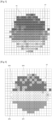
- FIG. 3 illustrates the pixel distance values of a DT point in the image.
- the processing unit UT is configured to process each image IMG generated by the pixel matrix PXM.
- the processing unit UT is configured to perform a partitioning of the pixels PX for each point DT of the image IMG.
- the processing unit UT is configured to define at least one group of pixels PX associated with this point DT.
- the processing unit UT is configured to group the pixels PX of the point DT having distance values that are close to each other. This makes it possible to identify different elements of the scene represented on the same point of the image. For example, pixels PX can be considered close enough to be grouped in the same group if the difference between their distance values is less than 2% of the average of the two distances (this value of 2% being a parameter of the algorithm that can be adjusted according to the performance of the time-of-flight sensor).
- the groups can be defined by a k-means partitioning algorithm.
- FIG. 4 illustrates the DT point of the Figure 3 in which pixels with close distance values were grouped into groups GP1, GP2, GP3, GP4.
- the processing unit is configured to calculate for each group a value representative of the pixel distance values PX of this group.
- This value representative of a group can be an average value of the pixel distance values PX of this group.
- the processing unit can be configured to merge these two groups. For example, representative values can be considered close when their difference is less than 2% of the average of the two distances (this 2% value being a parameter of the algorithm that can be adjusted according to the performance of the time-of-flight sensor).
- the processing unit is then configured to calculate a new value representative for the new group formed resulting from the merger of the two groups.
- the Figure 5 illustrates the point of the Figure 3 in which the GP3 and GP4 groups of pixels have been merged to form a new NGP3 group of pixels.
- the processing unit thus generates a final image in which the DT points of the initial image have as distance values the representative values calculated for each group defined for each DT point.
- Such a time-of-flight sensor makes it possible to detect several elements of the scene located on the same DT point of the image, and to return, for this DT point of the image, the same number of distance values as elements on this DT point.
- Such a time-of-flight sensor also makes it possible to limit the errors in distance values associated with certain PX pixels of a DT point in the image. Indeed, grouping the PX pixels having distance values close to each other can make it possible to extract the PX pixels having aberrant distance values. By not taking into account the PX pixels having aberrant distance values, the signal-to-noise ratio of such a sensor is improved.
- FIG. 6 illustrates a method of processing an image generated by a PXM pixel array of a time-of-flight sensor as described previously.
- the image generated by the PXM pixel array comprises several DT points.
- the method comprises an implementation 40 of an algorithm for partitioning the pixels PX of each point DT.
- the implementation of such an algorithm makes it possible to define groups of pixels PX in each point DT of the image.
- the method also comprises, for each group of each point DT, a calculation of a value representative of the distance values of the pixels PX of this group.
- the method may also comprise a merger 41 of the groups of the same point DT having representative values close to each other.
- the method then comprises, following the merger of the groups, a calculation 42 of a new representative value for the new group formed resulting from the merger of these groups.
Landscapes
- Engineering & Computer Science (AREA)
- Physics & Mathematics (AREA)
- Computer Networks & Wireless Communication (AREA)
- General Physics & Mathematics (AREA)
- Radar, Positioning & Navigation (AREA)
- Remote Sensing (AREA)
- Electromagnetism (AREA)
- Optical Radar Systems And Details Thereof (AREA)
Claims (8)
- Flugzeitsensor, der Folgendes umfasst:- eine Sendevorrichtung (EMT), die so konfiguriert ist, dass sie Lichtstrahlen in einer Szene aussendet, in der der Flugzeitsensor platziert ist,- eine lichtempfindliche Pixelmatrix (PXM), die so konfiguriert ist, dass sie Lichtsignale von der Szene empfängt und ein Bild (IMG) erzeugt, das Punkte (DT) veranschaulicht, die mit den von der Sendevorrichtung (EMT) ausgesendeten Strahlen verbunden sind, von Elementen der Szene reflektiert und von der Pixelmatrix empfangen werden, wobei jeder Punkt (DT) eine Vielzahl von Pixeln (PX) des Bildes abdeckt, wobei jedes Pixel des Bildes mit einem zwischen dem Flugzeitsensor und einem Element der Szene gemessenen Abstandswert verbunden ist,wobei der Flugzeitsensor dadurch gekennzeichnet ist, dass er auch eine Verarbeitungseinheit (UT) umfasst, die für jeden Punkt des Bildes für Folgendes konfiguriert ist:o Durchführen einer Partitionierung der Pixel (PX) des Punktes in mindestens eine Gruppe (GP1, GP2, GP3, GP4) von Pixeln (PX),o Berechnen eines repräsentativen Werts für die Abstandswerte der Pixel der Gruppe für jede Gruppe (GP1, GP2, GP3, GP4) von Pixeln (PX), wobei der repräsentative Abstandswert dann für jedes Pixel der Gruppe von Pixeln angewendet wird.
- Flugzeitsensor nach Anspruch 1, wobei die Verarbeitungseinheit (UT) auch so konfiguriert ist, dass sie Gruppen (GP3, GP4) von Pixeln (PX) desselben Punkts (DT) zusammenführt, wenn die Differenz der für die Gruppen von Pixeln (PX) berechneten repräsentativen Werte unter einem bestimmten Schwellenwert liegt, und dann einen neuen repräsentativen Abstandswert für die neue Gruppe (NGP3) von Pixeln (PX) berechnet, die durch das Zusammenführen der Gruppen gebildet wurde.
- Flugzeitsensor nach einem der Ansprüche 1 oder 2, wobei das Partitionieren der Pixel (PX) jedes Punktes das Ausführen eines Segmentierungsalgorithmus umfasst.
- Flugzeitsensor nach Anspruch 3, wobei der Segmentierungsalgorithmus ein k-Mittelwert-Partitionsalgorithmus ist.
- Verfahren zum Messen von Abständen zwischen einem Flugzeitsensor und Elementen einer Szene, in der der Flugzeitsensor (TOF) platziert ist, wobei das Verfahren Folgendes umfasst:- Aussenden von Lichtstrahlen in der Szene durch eine Sendevorrichtung (EMT) des Flugzeitsensors (TOF),- Empfangen der Lichtsignale von der Szene durch eine Pixelmatrix (PXM) des Flugzeitsensors (CPT), und- Erzeugen eines Bildes, das Punkte (DT) verschaulicht, die mit den von der Sendevorrichtung (EMT) ausgesendeten Strahlen verbunden sind, von Elementen der Szene reflektiert und von der Pixelmatrix empfangen werden, durch die Pixelmatrix (PX), wobei jeder Punkt (DT) eine Vielzahl von Pixeln (PX) des Bildes abdeckt, wobei jedes Pixel des Bildes mit einem zwischen dem Flugzeitsensor und einem Element der Szene gemessenen Abstandswert verbunden ist,wobei das Verfahren dadurch gekennzeichnet ist, dass es für jeden Punkt (DT) des Bildes Folgendes umfasst:- Partitionieren der Pixel (PX) des Punktes in mindestens eine Gruppe (GP1, GP2, GP3, GP4) von Pixeln (PX),- Berechnen eines repräsentativen Werts der Abstandswerte der Pixel der Gruppe für jede Gruppe (GP1, GP2, GP3, GP4) von Pixeln (PX), wobei der repräsentative Abstandswert dann für jedes Pixel der Gruppe von Pixeln angewendet wird.
- Verfahren nach Anspruch 5, das ferner das Zusammenführen der Gruppen (GP3, GP4) desselben Punktes (DT), wenn die Differenz der für die Gruppen von Pixeln (PX) berechneten repräsentativen Werte unter einem bestimmten Schwellenwert liegt, und anschließend das Berechnen eines neuen repräsentativen Abstandswerts für die neue Gruppe (NGP3), die durch das Zusammenführen der Gruppen (GP3, GP4) gebildet wurde, umfasst.
- Verfahren nach einem der Ansprüche 5 oder 6, wobei das Partitionieren der Pixel (PX) jedes Punktes (DT) das Ausführen eines Segmentierungsalgorithmus umfasst.
- Verfahren nach Anspruch 7, wobei der Segmentierungsalgorithmus ein k-Mittelwert-Partitionsalgorithmus ist.
Applications Claiming Priority (1)
| Application Number | Priority Date | Filing Date | Title |
|---|---|---|---|
| FR2205763A FR3136558B1 (fr) | 2022-06-14 | 2022-06-14 | Capteur temps de vol et procédé de mesure de distances |
Publications (2)
| Publication Number | Publication Date |
|---|---|
| EP4293391A1 EP4293391A1 (de) | 2023-12-20 |
| EP4293391B1 true EP4293391B1 (de) | 2025-03-19 |
Family
ID=82781367
Family Applications (1)
| Application Number | Title | Priority Date | Filing Date |
|---|---|---|---|
| EP23177879.6A Active EP4293391B1 (de) | 2022-06-14 | 2023-06-07 | Flugzeitsensor und verfahren zur abstandsmessung |
Country Status (4)
| Country | Link |
|---|---|
| US (1) | US20230408698A1 (de) |
| EP (1) | EP4293391B1 (de) |
| CN (1) | CN117761705A (de) |
| FR (1) | FR3136558B1 (de) |
Family Cites Families (6)
| Publication number | Priority date | Publication date | Assignee | Title |
|---|---|---|---|---|
| US9111444B2 (en) * | 2012-10-31 | 2015-08-18 | Raytheon Company | Video and lidar target detection and tracking system and method for segmenting moving targets |
| EP2955544B1 (de) * | 2014-06-11 | 2020-06-17 | Sony Depthsensing Solutions N.V. | TOF-Kamerasystem und Verfahren zum Messen einer Entfernung mit dem System |
| US20190068853A1 (en) * | 2017-08-22 | 2019-02-28 | Microsoft Technology Licensing, Llc | Structured light and flood fill light illuminator |
| US11187804B2 (en) * | 2018-05-30 | 2021-11-30 | Qualcomm Incorporated | Time of flight range finder for a structured light system |
| CN110988846B (zh) * | 2019-04-22 | 2023-07-18 | 威力登激光雷达美国有限公司 | 可用于激光雷达的噪点识别方法以及激光雷达系统 |
| US11132804B2 (en) * | 2020-01-07 | 2021-09-28 | Himax Technologies Limited | Hybrid depth estimation system |
-
2022
- 2022-06-14 FR FR2205763A patent/FR3136558B1/fr active Active
-
2023
- 2023-06-07 EP EP23177879.6A patent/EP4293391B1/de active Active
- 2023-06-14 CN CN202310703481.1A patent/CN117761705A/zh active Pending
- 2023-06-14 US US18/334,501 patent/US20230408698A1/en active Pending
Also Published As
| Publication number | Publication date |
|---|---|
| US20230408698A1 (en) | 2023-12-21 |
| FR3136558A1 (fr) | 2023-12-15 |
| EP4293391A1 (de) | 2023-12-20 |
| CN117761705A (zh) | 2024-03-26 |
| FR3136558B1 (fr) | 2024-06-21 |
Similar Documents
| Publication | Publication Date | Title |
|---|---|---|
| EP2904425B1 (de) | Verfahren und vorrichtung für den nachweis von ionisierender strahlung unter verwendung eines pixelierten fotodetektors | |
| EP1433012B1 (de) | Passive optoelektronische überwachungseinrichtung | |
| EP2202538A1 (de) | Passives Bildanzeigesystem, das mit einem Entfernungsmesser ausgestattet ist | |
| WO2009053461A1 (fr) | Procede de detection d'une cible | |
| EP4293391B1 (de) | Flugzeitsensor und verfahren zur abstandsmessung | |
| WO2020104677A1 (fr) | Procédé d'échange de données entre des drones d'un essaim de drones | |
| EP0001535B1 (de) | Bildverarbeitungsverfahren und Vorrichtung für ein Sichtbarmachungssystem | |
| EP1995693A1 (de) | Verfahren zur Erfassung eines Gegenstands in Bewegung in einem Bildstrom | |
| EP4290454B1 (de) | Verfahren und vorrichtung zur segmentierung mindestens eines für ein photovoltaikkraftwerk repräsentativen quellfarbbildes | |
| EP2517039B1 (de) | Vorrichtung zur erkennung von laserspots mit einem matrixdeviometer | |
| FR2832799A1 (fr) | Procedure de detection optique de gaz a distance | |
| EP1710767A1 (de) | Verfahren und System zur Erfassung des Vorliegens eines hinderlichen Objekts und Aktivierungsmodul für dieses System | |
| FR2753796A1 (fr) | Detecteur photosensible et mosaique de detecteurs photosensibles pour la detection d'eclats lumineux et applications | |
| WO2023119933A1 (ja) | 光子数識別システム、光子数識別方法および光子数識別処理プログラム | |
| EP3360055B1 (de) | Verfahren zur optimierung der zerlegung eines asynchronen signals | |
| FR3121205A1 (fr) | Estimation d’un décalage de distance dans un dispositif de mesure indirecte par temps de vol, et dispositif correspondant | |
| WO2021250258A1 (fr) | Procédé de mise en œuvre d'un dispositif lidar avec descripteurs | |
| FR3090124B1 (fr) | Capteur de temps de vol et système de surveillance comportant un tel capteur | |
| WO2025133491A1 (fr) | Système d'alerte laser et procédé associé de détection et de caractérisation d'un rayonnement laser | |
| EP4167197A1 (de) | Verfahren zur kalibrierung einer lösung zur wiedererkennung von objekten, bei dem ein netzwerk aus mehreren kameras eingesetzt wird | |
| FR3072783A1 (fr) | Systeme de detection de rayonnement ionisant et procede de detection associe | |
| EP4389567A1 (de) | Verfahren zur bestimmung von detektionsschwellen einer vorrichtung mit konstanter falschalarmrate eines sensors, vorrichtungen und verfahren dafür | |
| EP4435465A1 (de) | Verfahren zur identifizierung eines radarsenders und entsprechendes identifizierungssystem | |
| FR3140951A1 (fr) | Procede de detection d’un objet par un capteur temps de vol | |
| WO2022189389A1 (fr) | Procede et dispositif de calibration d'un capteur de profondeur d'environnement |
Legal Events
| Date | Code | Title | Description |
|---|---|---|---|
| PUAI | Public reference made under article 153(3) epc to a published international application that has entered the european phase |
Free format text: ORIGINAL CODE: 0009012 |
|
| STAA | Information on the status of an ep patent application or granted ep patent |
Free format text: STATUS: REQUEST FOR EXAMINATION WAS MADE |
|
| 17P | Request for examination filed |
Effective date: 20230607 |
|
| AK | Designated contracting states |
Kind code of ref document: A1 Designated state(s): AL AT BE BG CH CY CZ DE DK EE ES FI FR GB GR HR HU IE IS IT LI LT LU LV MC ME MK MT NL NO PL PT RO RS SE SI SK SM TR |
|
| GRAP | Despatch of communication of intention to grant a patent |
Free format text: ORIGINAL CODE: EPIDOSNIGR1 |
|
| STAA | Information on the status of an ep patent application or granted ep patent |
Free format text: STATUS: GRANT OF PATENT IS INTENDED |
|
| RIC1 | Information provided on ipc code assigned before grant |
Ipc: G01S 7/48 20060101ALI20241024BHEP Ipc: G01S 7/4915 20200101ALI20241024BHEP Ipc: G01S 7/4914 20200101ALI20241024BHEP Ipc: G01S 17/894 20200101AFI20241024BHEP |
|
| INTG | Intention to grant announced |
Effective date: 20241031 |
|
| GRAS | Grant fee paid |
Free format text: ORIGINAL CODE: EPIDOSNIGR3 |
|
| GRAA | (expected) grant |
Free format text: ORIGINAL CODE: 0009210 |
|
| STAA | Information on the status of an ep patent application or granted ep patent |
Free format text: STATUS: THE PATENT HAS BEEN GRANTED |
|
| AK | Designated contracting states |
Kind code of ref document: B1 Designated state(s): AL AT BE BG CH CY CZ DE DK EE ES FI FR GB GR HR HU IE IS IT LI LT LU LV MC ME MK MT NL NO PL PT RO RS SE SI SK SM TR |
|
| REG | Reference to a national code |
Ref country code: GB Ref legal event code: FG4D Free format text: NOT ENGLISH |
|
| REG | Reference to a national code |
Ref country code: CH Ref legal event code: EP |
|
| REG | Reference to a national code |
Ref country code: DE Ref legal event code: R096 Ref document number: 602023002451 Country of ref document: DE |
|
| REG | Reference to a national code |
Ref country code: IE Ref legal event code: FG4D Free format text: LANGUAGE OF EP DOCUMENT: FRENCH |
|
| PG25 | Lapsed in a contracting state [announced via postgrant information from national office to epo] |
Ref country code: RS Free format text: LAPSE BECAUSE OF FAILURE TO SUBMIT A TRANSLATION OF THE DESCRIPTION OR TO PAY THE FEE WITHIN THE PRESCRIBED TIME-LIMIT Effective date: 20250619 |
|
| PG25 | Lapsed in a contracting state [announced via postgrant information from national office to epo] |
Ref country code: FI Free format text: LAPSE BECAUSE OF FAILURE TO SUBMIT A TRANSLATION OF THE DESCRIPTION OR TO PAY THE FEE WITHIN THE PRESCRIBED TIME-LIMIT Effective date: 20250319 |
|
| PGFP | Annual fee paid to national office [announced via postgrant information from national office to epo] |
Ref country code: DE Payment date: 20250520 Year of fee payment: 3 |
|
| REG | Reference to a national code |
Ref country code: LT Ref legal event code: MG9D |
|
| PG25 | Lapsed in a contracting state [announced via postgrant information from national office to epo] |
Ref country code: NO Free format text: LAPSE BECAUSE OF FAILURE TO SUBMIT A TRANSLATION OF THE DESCRIPTION OR TO PAY THE FEE WITHIN THE PRESCRIBED TIME-LIMIT Effective date: 20250619 |
|
| PG25 | Lapsed in a contracting state [announced via postgrant information from national office to epo] |
Ref country code: HR Free format text: LAPSE BECAUSE OF FAILURE TO SUBMIT A TRANSLATION OF THE DESCRIPTION OR TO PAY THE FEE WITHIN THE PRESCRIBED TIME-LIMIT Effective date: 20250319 |
|
| PG25 | Lapsed in a contracting state [announced via postgrant information from national office to epo] |
Ref country code: LV Free format text: LAPSE BECAUSE OF FAILURE TO SUBMIT A TRANSLATION OF THE DESCRIPTION OR TO PAY THE FEE WITHIN THE PRESCRIBED TIME-LIMIT Effective date: 20250319 |
|
| PG25 | Lapsed in a contracting state [announced via postgrant information from national office to epo] |
Ref country code: BG Free format text: LAPSE BECAUSE OF FAILURE TO SUBMIT A TRANSLATION OF THE DESCRIPTION OR TO PAY THE FEE WITHIN THE PRESCRIBED TIME-LIMIT Effective date: 20250319 Ref country code: GR Free format text: LAPSE BECAUSE OF FAILURE TO SUBMIT A TRANSLATION OF THE DESCRIPTION OR TO PAY THE FEE WITHIN THE PRESCRIBED TIME-LIMIT Effective date: 20250620 |
|
| REG | Reference to a national code |
Ref country code: NL Ref legal event code: MP Effective date: 20250319 |
|
| REG | Reference to a national code |
Ref country code: AT Ref legal event code: MK05 Ref document number: 1777382 Country of ref document: AT Kind code of ref document: T Effective date: 20250319 |
|
| PG25 | Lapsed in a contracting state [announced via postgrant information from national office to epo] |
Ref country code: NL Free format text: LAPSE BECAUSE OF FAILURE TO SUBMIT A TRANSLATION OF THE DESCRIPTION OR TO PAY THE FEE WITHIN THE PRESCRIBED TIME-LIMIT Effective date: 20250319 |
|
| PG25 | Lapsed in a contracting state [announced via postgrant information from national office to epo] |
Ref country code: SE Free format text: LAPSE BECAUSE OF FAILURE TO SUBMIT A TRANSLATION OF THE DESCRIPTION OR TO PAY THE FEE WITHIN THE PRESCRIBED TIME-LIMIT Effective date: 20250319 |
|
| PG25 | Lapsed in a contracting state [announced via postgrant information from national office to epo] |
Ref country code: SM Free format text: LAPSE BECAUSE OF FAILURE TO SUBMIT A TRANSLATION OF THE DESCRIPTION OR TO PAY THE FEE WITHIN THE PRESCRIBED TIME-LIMIT Effective date: 20250319 |
|
| PG25 | Lapsed in a contracting state [announced via postgrant information from national office to epo] |
Ref country code: PT Free format text: LAPSE BECAUSE OF FAILURE TO SUBMIT A TRANSLATION OF THE DESCRIPTION OR TO PAY THE FEE WITHIN THE PRESCRIBED TIME-LIMIT Effective date: 20250721 Ref country code: ES Free format text: LAPSE BECAUSE OF FAILURE TO SUBMIT A TRANSLATION OF THE DESCRIPTION OR TO PAY THE FEE WITHIN THE PRESCRIBED TIME-LIMIT Effective date: 20250319 |
|
| PG25 | Lapsed in a contracting state [announced via postgrant information from national office to epo] |
Ref country code: IT Free format text: LAPSE BECAUSE OF FAILURE TO SUBMIT A TRANSLATION OF THE DESCRIPTION OR TO PAY THE FEE WITHIN THE PRESCRIBED TIME-LIMIT Effective date: 20250319 Ref country code: PL Free format text: LAPSE BECAUSE OF FAILURE TO SUBMIT A TRANSLATION OF THE DESCRIPTION OR TO PAY THE FEE WITHIN THE PRESCRIBED TIME-LIMIT Effective date: 20250319 |
|
| PG25 | Lapsed in a contracting state [announced via postgrant information from national office to epo] |
Ref country code: AT Free format text: LAPSE BECAUSE OF FAILURE TO SUBMIT A TRANSLATION OF THE DESCRIPTION OR TO PAY THE FEE WITHIN THE PRESCRIBED TIME-LIMIT Effective date: 20250319 |
|
| PG25 | Lapsed in a contracting state [announced via postgrant information from national office to epo] |
Ref country code: EE Free format text: LAPSE BECAUSE OF FAILURE TO SUBMIT A TRANSLATION OF THE DESCRIPTION OR TO PAY THE FEE WITHIN THE PRESCRIBED TIME-LIMIT Effective date: 20250319 Ref country code: CZ Free format text: LAPSE BECAUSE OF FAILURE TO SUBMIT A TRANSLATION OF THE DESCRIPTION OR TO PAY THE FEE WITHIN THE PRESCRIBED TIME-LIMIT Effective date: 20250319 |
|
| PG25 | Lapsed in a contracting state [announced via postgrant information from national office to epo] |
Ref country code: RO Free format text: LAPSE BECAUSE OF FAILURE TO SUBMIT A TRANSLATION OF THE DESCRIPTION OR TO PAY THE FEE WITHIN THE PRESCRIBED TIME-LIMIT Effective date: 20250319 |
|
| PG25 | Lapsed in a contracting state [announced via postgrant information from national office to epo] |
Ref country code: SK Free format text: LAPSE BECAUSE OF FAILURE TO SUBMIT A TRANSLATION OF THE DESCRIPTION OR TO PAY THE FEE WITHIN THE PRESCRIBED TIME-LIMIT Effective date: 20250319 |
|
| PG25 | Lapsed in a contracting state [announced via postgrant information from national office to epo] |
Ref country code: IS Free format text: LAPSE BECAUSE OF FAILURE TO SUBMIT A TRANSLATION OF THE DESCRIPTION OR TO PAY THE FEE WITHIN THE PRESCRIBED TIME-LIMIT Effective date: 20250719 |
|
| REG | Reference to a national code |
Ref country code: DE Ref legal event code: R097 Ref document number: 602023002451 Country of ref document: DE |
|
| PG25 | Lapsed in a contracting state [announced via postgrant information from national office to epo] |
Ref country code: DK Free format text: LAPSE BECAUSE OF FAILURE TO SUBMIT A TRANSLATION OF THE DESCRIPTION OR TO PAY THE FEE WITHIN THE PRESCRIBED TIME-LIMIT Effective date: 20250319 |
|
| PLBE | No opposition filed within time limit |
Free format text: ORIGINAL CODE: 0009261 |
|
| STAA | Information on the status of an ep patent application or granted ep patent |
Free format text: STATUS: NO OPPOSITION FILED WITHIN TIME LIMIT |
|
| REG | Reference to a national code |
Ref country code: CH Ref legal event code: L10 Free format text: ST27 STATUS EVENT CODE: U-0-0-L10-L00 (AS PROVIDED BY THE NATIONAL OFFICE) Effective date: 20260128 |
|
| PG25 | Lapsed in a contracting state [announced via postgrant information from national office to epo] |
Ref country code: MC Free format text: LAPSE BECAUSE OF FAILURE TO SUBMIT A TRANSLATION OF THE DESCRIPTION OR TO PAY THE FEE WITHIN THE PRESCRIBED TIME-LIMIT Effective date: 20250319 |
|
| PG25 | Lapsed in a contracting state [announced via postgrant information from national office to epo] |
Ref country code: LU Free format text: LAPSE BECAUSE OF NON-PAYMENT OF DUE FEES Effective date: 20250607 |
|
| 26N | No opposition filed |
Effective date: 20251222 |
|
| REG | Reference to a national code |
Ref country code: BE Ref legal event code: MM Effective date: 20250630 |
|
| PG25 | Lapsed in a contracting state [announced via postgrant information from national office to epo] |
Ref country code: IE Free format text: LAPSE BECAUSE OF NON-PAYMENT OF DUE FEES Effective date: 20250607 |
|
| PG25 | Lapsed in a contracting state [announced via postgrant information from national office to epo] |
Ref country code: BE Free format text: LAPSE BECAUSE OF NON-PAYMENT OF DUE FEES Effective date: 20250630 |
|
| PG25 | Lapsed in a contracting state [announced via postgrant information from national office to epo] |
Ref country code: FR Free format text: LAPSE BECAUSE OF NON-PAYMENT OF DUE FEES Effective date: 20250630 |