EP4293261A1 - Measuring device - Google Patents
Measuring device Download PDFInfo
- Publication number
- EP4293261A1 EP4293261A1 EP22752875.9A EP22752875A EP4293261A1 EP 4293261 A1 EP4293261 A1 EP 4293261A1 EP 22752875 A EP22752875 A EP 22752875A EP 4293261 A1 EP4293261 A1 EP 4293261A1
- Authority
- EP
- European Patent Office
- Prior art keywords
- space
- exhaust valve
- air
- pressure
- measuring device
- Prior art date
- Legal status (The legal status is an assumption and is not a legal conclusion. Google has not performed a legal analysis and makes no representation as to the accuracy of the status listed.)
- Pending
Links
Images




Classifications
-
- F—MECHANICAL ENGINEERING; LIGHTING; HEATING; WEAPONS; BLASTING
- F04—POSITIVE - DISPLACEMENT MACHINES FOR LIQUIDS; PUMPS FOR LIQUIDS OR ELASTIC FLUIDS
- F04B—POSITIVE-DISPLACEMENT MACHINES FOR LIQUIDS; PUMPS
- F04B45/00—Pumps or pumping installations having flexible working members and specially adapted for elastic fluids
- F04B45/04—Pumps or pumping installations having flexible working members and specially adapted for elastic fluids having plate-like flexible members, e.g. diaphragms
- F04B45/047—Pumps having electric drive
-
- A—HUMAN NECESSITIES
- A61—MEDICAL OR VETERINARY SCIENCE; HYGIENE
- A61B—DIAGNOSIS; SURGERY; IDENTIFICATION
- A61B5/00—Measuring for diagnostic purposes; Identification of persons
- A61B5/02—Detecting, measuring or recording for evaluating the cardiovascular system, e.g. pulse, heart rate, blood pressure or blood flow
- A61B5/021—Measuring pressure in heart or blood vessels
- A61B5/02141—Details of apparatus construction, e.g. pump units or housings therefor, cuff pressurising systems, arrangements of fluid conduits or circuits
-
- A—HUMAN NECESSITIES
- A61—MEDICAL OR VETERINARY SCIENCE; HYGIENE
- A61B—DIAGNOSIS; SURGERY; IDENTIFICATION
- A61B5/00—Measuring for diagnostic purposes; Identification of persons
- A61B5/02—Detecting, measuring or recording for evaluating the cardiovascular system, e.g. pulse, heart rate, blood pressure or blood flow
- A61B5/021—Measuring pressure in heart or blood vessels
- A61B5/022—Measuring pressure in heart or blood vessels by applying pressure to close blood vessels, e.g. against the skin; Ophthalmodynamometers
- A61B5/0225—Measuring pressure in heart or blood vessels by applying pressure to close blood vessels, e.g. against the skin; Ophthalmodynamometers the pressure being controlled by electric signals, e.g. derived from Korotkoff sounds
-
- A—HUMAN NECESSITIES
- A61—MEDICAL OR VETERINARY SCIENCE; HYGIENE
- A61B—DIAGNOSIS; SURGERY; IDENTIFICATION
- A61B5/00—Measuring for diagnostic purposes; Identification of persons
- A61B5/02—Detecting, measuring or recording for evaluating the cardiovascular system, e.g. pulse, heart rate, blood pressure or blood flow
- A61B5/021—Measuring pressure in heart or blood vessels
- A61B5/022—Measuring pressure in heart or blood vessels by applying pressure to close blood vessels, e.g. against the skin; Ophthalmodynamometers
- A61B5/0235—Valves specially adapted therefor
-
- F—MECHANICAL ENGINEERING; LIGHTING; HEATING; WEAPONS; BLASTING
- F04—POSITIVE - DISPLACEMENT MACHINES FOR LIQUIDS; PUMPS FOR LIQUIDS OR ELASTIC FLUIDS
- F04B—POSITIVE-DISPLACEMENT MACHINES FOR LIQUIDS; PUMPS
- F04B45/00—Pumps or pumping installations having flexible working members and specially adapted for elastic fluids
- F04B45/04—Pumps or pumping installations having flexible working members and specially adapted for elastic fluids having plate-like flexible members, e.g. diaphragms
- F04B45/043—Pumps or pumping installations having flexible working members and specially adapted for elastic fluids having plate-like flexible members, e.g. diaphragms two or more plate-like pumping flexible members in parallel
-
- A—HUMAN NECESSITIES
- A61—MEDICAL OR VETERINARY SCIENCE; HYGIENE
- A61B—DIAGNOSIS; SURGERY; IDENTIFICATION
- A61B2560/00—Constructional details of operational features of apparatus; Accessories for medical measuring apparatus
- A61B2560/02—Operational features
-
- A—HUMAN NECESSITIES
- A61—MEDICAL OR VETERINARY SCIENCE; HYGIENE
- A61B—DIAGNOSIS; SURGERY; IDENTIFICATION
- A61B2560/00—Constructional details of operational features of apparatus; Accessories for medical measuring apparatus
- A61B2560/04—Constructional details of apparatus
Definitions
- the present invention relates to a measuring device.
- a so-called pressure rising type measuring device In measuring devices such as a blood pressure monitor, a so-called pressure rising type measuring device is known, the pressure rising type measuring device measuring blood pressure during pressurization, not in a depressurization process after pressurization. In the pressure rising type measuring device, it is required to rapidly exhaust air pressurized in a cuff when the pressurization is stopped. For example, a measuring device using a solenoid valve for rapidly exhausting pressurized air is known.
- Patent Document 1 JP 2018-171311 A
- Providing a solenoid valve complicates a structure of the measuring device, increases a manufacturing cost and power consumption, and hinders miniaturization of the measuring device.
- an object is to provide a measuring device capable of simplifying a structure.
- a measuring device in one aspect, includes a first space for pressurizing a pressurization target and a second space independent of the first space.
- the measuring device includes a first exhaust valve configured to close or open a communication port communicating the first space with another space. An open/closed state of the first exhaust valve changes in accordance with a pressure difference between the first space and the second space.
- the structure of the measuring device can be simplified.
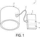
- FIG. 1 is a perspective view illustrating an example of an overall configuration of a measuring device according to an embodiment.
- a measuring device 1 in each embodiment is, for example, an electronic blood pressure monitor, and includes a cuff 2, a main body 3, and a tube 4 connecting the cuff 2 and the main body 3.
- the main body 3 includes a pump unit 5 and a control unit 6.
- the cuff 2 is an example of a pressurization target.
- the pump unit 5 of the main body 3 supplies a fluid to the cuff 2 via the tube 4.
- a fluid In each embodiment, for example, air is supplied as the fluid.
- the control unit 6 of the main body 3 controls, for example, start and stop of the pump unit 5.
- the cuff 2 is attached to a measurement site such as a wrist of a subject, for example.
- the cuff 2 pressurizes the measurement site with air supplied from the main body 3.
- the air supplied to the cuff 2 is not exhausted except from the tube 4.
- the air supplied to the cuff 2 is exhausted through the tube 4 in accordance with the operation of the pump unit 5 described below.
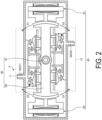
- FIG. 2 is a cross-sectional view illustrating an example of the pump according to the first embodiment.
- the pump unit 5 includes a drive mechanism 80, a swing mechanism 90, a pair of pressure regulating mechanisms 11 and 12, and a pair of discharge ports 57 and 58.
- the number of pressure regulating mechanisms included in the pump unit 5 is not limited to two, and may be one or three or more.
- the pair of pressure regulating mechanisms 11 and 12 may be referred to as a pressure regulating mechanism 10 when the pressure regulating mechanisms 11 and 12 are not distinguished from each other.
- the pair of discharge ports 57 and 58 may be referred to as a discharge port 59 when the discharge ports 57 and 58 are not distinguished from each other.
- the drive mechanism 80 is an operation unit swinging the swing mechanism 90, and includes, for example, a pair of actuators 81 and 82.
- the drive mechanism 80 starts or stops the operation based on a control signal transmitted from the control unit 6.
- the actuators 81 and 82 are, for example, vibration actuators using a solenoid, a motor, or the like.
- a well-known actuator such as an actuator using a piezoelectric element or an actuator using resonance of an elastic body can be applied.
- the swing mechanism 90 illustrated in FIG. 2 includes, for example, a shaft 91 and a swing body 92.
- the swing body 92 swings in the vertical direction in the drawing with the shaft 91 as a swing axis, thereby pressing a pressing portion of the pressure regulating mechanism 10 described below.
- the pressure regulating mechanism 10 pressurizes the cuff 2 by supplying air to the cuff 2 via the discharge port 59 and the tube 4, and depressurizes the cuff 2 by exhausting the air supplied to the cuff 2.
- the pair of pressure regulating mechanisms 11 and 12 are both connected to the cuff 2 via the tube 4.
- FIG. 3 is a cross-sectional view illustrating an example of the pressure regulating mechanism in the first embodiment. Note that FIG. 3 illustrates a state where neither pressurization nor depressurization is performed.
- the pressure regulating mechanism 10 according to the first embodiment includes first pressurizing units 20 and 30, a first space 52, a first exhaust valve 60, and a pressure regulating unit 70. The two first pressurizing units 20 and 30 are connected to the same first space 52.
- the first pressurizing unit 20 includes a movable portion 21, a sealed space 22, pressing portions 23 and 24, an intake port 25, an intake valve 26, and a third exhaust valve 27.
- the movable portion 21 constitutes a part of the sealed space 22.
- the movable portion 21 changes the volume of the sealed space 22 by changing the position and inclination in conjunction with the pressing portions 23 and 24.
- the movable portion 21 is a diaphragm formed of a material having flexibility such as rubber.
- the sealed space 22 repeats intake and exhaust in accordance with increase and decrease of the volume.
- air is supplied to the sealed space 22 via the intake port 25 and the intake valve 26.
- air is supplied to the first space 52 via the third exhaust valve 27.
- the pressing portions 23 and 24 displace the position and inclination of the movable portion 21 in conjunction with the swing body 92.
- the pressing portions 23 and 24 push up the movable portion 21 of the first pressurizing unit 20.
- the volume of the sealed space 22 decreases.
- the swing body 92 illustrated in FIG. 2 swings in the direction indicated by the arrow D2
- air is supplied to the sealed space 22 of the first pressurizing unit 20 via the intake port 25 and the intake valve 26. Accordingly, the pressing portions 23 and 24 are pressed down by the movable portion 21.
- the intake port 25 connects the sealed space 22 to another space such as the outside of the device.
- the intake valve 26 is, for example, a check valve.
- the intake valve 26 allows a flow of air from the intake port 25 to the sealed space 22, and restricts a flow of air from the sealed space 22 to the intake port 25.
- the third exhaust valve 27 is provided between the sealed space 22 and the first space 52.
- the third exhaust valve 27 is also, for example, a check valve.
- the third exhaust valve 27 allows a flow of air from the sealed space 22 to the first space 52 and restricts a flow of air from the first space 52 to the sealed space 22.
- the first pressurizing unit 30 further includes a second exhaust valve 38 in addition to the movable portion 21, the sealed space 22, the pressing portions 23 and 24, the intake port 25, the intake valve 26, and the third exhaust valve 27.
- the third exhaust valve 27 of the first pressurizing unit 30 is also provided between the sealed space 22 of the first pressurizing unit 30 and the first space 52.
- the second exhaust valve 38 is provided between the sealed space 22 and a second space 72 of the pressure regulating unit 70 to be described below.
- the second exhaust valve 38 is also, for example, a check valve.
- the second exhaust valve 38 allows a flow of air from the sealed space 22 to the second space 72, and restricts a flow of air from the second space 72 to the sealed space 22.
- the first pressurizing unit 30 supplies air to the first space 52, and also supplies air to the second space 72.
- the first pressurizing unit 30 and the first pressurizing unit 20 in the first embodiment are disposed at positions facing each other, across the shaft 91, in the direction in which the swing body 92 extends. That is, when the swing body 92 illustrated in FIG. 2 swings in the direction indicated by the arrow D1, air is supplied to the sealed space 22 of the first pressurizing unit 20, while air is supplied from the sealed space 22 of the first pressurizing unit 30 to the first space 52. Conversely, when the swing body 92 illustrated in FIG. 2 swings in the direction indicated by the arrow D2, air is supplied from the sealed space 22 of the first pressurizing unit 20 to the first space 52, while air is supplied to the sealed space 22 of the first pressurizing unit 30. Thus, air is continuously supplied from the first pressurizing units 20 and 30 to the first space 52.
- the discharge port 59 connects the first space 52 and the tube 4.
- the pair of discharge ports 57 and 58 are provided corresponding to the pair of pressure regulating mechanisms 11 and 12, respectively. That is, the first space 52 in the pressure regulating mechanism 11 is connected to the cuff 2 via the discharge port 57 and the tube 4. Similarly, the first space 52 in the pressure regulating mechanism 12 is connected to the cuff 2 via the discharge port 58 and the tube 4. As a result, air is supplied to the cuff 2 from both of the pair of pressure regulating mechanisms 11 and 12.
- air is supplied to the first space 52 of the pressure regulating mechanism 10 from the first pressurizing unit 20 and the first pressurizing unit 30.
- the first space 52 and the cuff 2 constitute a sealed space when the first exhaust valve 60 described below is in a closed state.
- the air supplied to the first space 52 is supplied to the cuff 2 via the discharge port 59 and the tube 4, thereby pressurizing the cuff 2.
- the air in the first space 52 is exhausted from the first exhaust valve 60 to the other space.
- air is also exhausted via the first exhaust valve 60 from the cuff 2 connected via the discharge port 59 and the tube 4.
- the air pressure in the first space 52 and the cuff 2 increases according to the pressurization by the first pressurizing unit 20 and the first pressurizing unit 30, with the air pressure in the other space as the lower limit.
- the first exhaust valve 60 in the closed state may be referred to as a first exhaust valve 60c
- the first exhaust valve 60 in the open state may be referred to as a first exhaust valve 60o.
- the pressure regulating unit 70 illustrated in FIG. 3 includes the second space 72 and an air leakage valve 79.
- the second space 72 is a space independent of the first space 52.
- the second space 72 is not a sealed space, but communicates with the other space via the air leakage valve 79, and air constantly leaks to the other space.
- air is supplied to the second space 72 from the first pressurizing unit 30 illustrated in FIG. 3 via the second exhaust valve 38. Further, the amount of air supplied by the first pressurizing unit 30 is larger than the amount of air leaking from the air leakage valve 79. That is, in the first embodiment, the air pressure in the second space 72 increases according to the pressurization by the first pressurizing unit 30 with the air pressure in the other space as a lower limit. In this case, as will be described below, the second space 72 is pressurized by the first pressurizing unit 30, so that the air pressure inside the second space 72 becomes higher than the air pressure inside the first space 52.
- the air supplied into the second space 72 leaks from the air leakage valve 79 to the other space.
- the air pressure in the second space 72 rapidly approaches the air pressure in the other space.
- the air pressure inside the second space 72 becomes lower than the air pressure inside the first space 52.
- the first exhaust valve 60 closes or opens the first space 52 and the other space such as the outside of the device.
- the first exhaust valve 60 is provided, for example, between the first space 52 and the second space 72.
- the first exhaust valve 60 is, for example, a check valve, and regulates the flow of air from the other space to the first space 52 and the flow of air from the second space 72 to the other space.
- the first exhaust valve 60 includes a first surface 61 facing the first space 52 and a second surface 62 facing the second space 72.
- the first exhaust valve 60 in the embodiment is, for example, a rapid exhaust valve.
- the pressure receiving area S1 of the first surface 61 with respect to the first space 52 and the pressure receiving area S1 with respect to the second space 72 are substantially the same.
- the open/closed state of the first exhaust valve 60 changes according to the air pressure difference (differential pressure) between the first space 52 and the second space 72.
- the first exhaust valve 60 changes between the open state 60o and the closed state 60c by, for example, changing position or changing shape, such as the size of an opening, in accordance with the differential pressure between the first space 52 and the second space 72.
- the first exhaust valve 60 is in the closed state when the air pressure in the second space 72 is equal to or higher than the air pressure in the first space 52. In this case, since the first space 52 is closed with respect to the other space, the air in the first space 52 is exhausted from the discharge port 59 to the cuff 2.
- the first exhaust valve 60 is in the open state when the air pressure in the second space 72 is lower than the air pressure in the first space 52.
- the air in the first space 52 is exhausted to the other space via the first exhaust valve 60, whereby the air pressure in the first space 52 rapidly approaches the air pressure in the other space.
- the air supplied from the first space 52 to the cuff 2 is also sucked into the first space 52, so the air pressure in the cuff 2 also decreases rapidly.
- the volume of the second space 72 is much smaller than the volume of the first space 52.
- the increase of the air pressure in the second space 72 is faster than the increase of the air pressure in the first space 52.
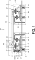
- FIG. 4 is a cross-sectional view illustrating an example of the intake state in the pressure regulating mechanism according to the first embodiment. As illustrated in FIG.
- the pressing portions 23 and 24 move up and down in the directions indicated by the arrows, so that air is supplied from the first pressurizing units 20 and 30 to the first space 52 as indicated by arrows A1 and A3. Similarly, as indicated by the arrow A2, air is also supplied from the first pressurizing unit 30 to the second space 72.
- the amount of air illustrated by the arrow A2 supplied to the second space 72 is larger than the amount of air illustrated by the arrow L1 leaking from the air leakage valve 79.
- the volume of the second space 72 is much smaller than the volume of the first space 52. For this reason, when the first pressurizing unit 30 starts pressurization, the air pressure P2 in the second space 72 rapidly increases compared to the increase in the air pressure P1 in the first space 52. As a result, the air pressure P2 in the second space 72 becomes higher than the air pressure P1 in the first space 52. As a result, since a differential pressure is generated between the first space 52 and the second space 72, the first exhaust valve 60 is closed.
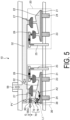
- FIG. 5 is a cross-sectional view illustrating an example of the exhaust state of the pressure regulating mechanism in the first embodiment.
- the air pressure P 1' in the first space 52 is high until the first exhaust valve 60 is opened. Since the volume of the second space 72 is small, the air pressure in the second space 72 rapidly decreases due to the leaking air indicated by the arrow L1'.
- the air pressure in the second space 72 becomes lower than the air pressure in the first space 52.
- the closed first exhaust valve 60 is opened, and the first space 52 is in the exhaust state.
- a gap G is formed by opening the first exhaust valve 60, and the air in the first space 52 is exhausted from the gap G to the other space by the differential pressure. This makes it possible to rapidly decrease the air pressure in the first space 52 and the cuff 2.
- the gap G is an example of a communication port.
- the measuring device 1 includes the first space 52 for pressurizing the pressurization target 2 and the second space 72 independent of the first space 52.
- the measuring device 1 includes the first exhaust valve 60 closing or opening the communication port G communicating the first space 52 with the other space.
- the open/closed state of the first exhaust valve 60 changes according to the pressure difference between the first space 52 and the second space 72.
- the first space 52 is pressurized by the plurality of first pressurizing units 20 and 30, and the second space 72 is pressurized by the first pressurizing unit 30.
- the differential pressure between the first space 52 and the second space 72 can be generated with a simple structure without largely changing the configuration of the existing pump.
- the structure of the pressure rising type measuring device can be simplified.
- the first pressurizing unit 30 pressurizing the first space 52 also supplies air to the second space 72, but the embodiment is not limited to this.
- the second space may be pressurized by another pressurizing unit different from the first pressurizing unit.
- a measuring device 1A according to the second embodiment has the same appearance as the appearance of the measuring device 1 illustrated in FIG. 1 except that the pump unit 5 is changed to a pump unit 5A, and therefore, the illustration is omitted.
- FIG. 6 is a cross-sectional view illustrating an example of a pump according to the second embodiment.
- the pump unit 5A in the second embodiment includes the drive mechanism 80, the swing mechanism 90, pressure regulating mechanisms 13 and 14, and the pair of discharge ports 57 and 58.
- the pressure regulating mechanisms 13 and 14 may be referred to as a pressure regulating mechanism 10A when the pressure regulating mechanisms 13 and 14 are not distinguished from each other.
- FIG. 7 is a cross-sectional view illustrating an example of the pressure regulating mechanism in the second embodiment.
- the pressure regulating mechanism 10A in the second embodiment includes two first pressurizing units 20a and 20b, a second pressurizing unit 40, the first space 52, the first exhaust valve 60, and a pressure regulating unit 70A.
- the first pressurizing units 20a and 20b in the second embodiment are disposed at positions facing each other, across the shaft 91 illustrated in FIG. 6 , in the direction in which the swing body 92 extends.
- the first pressurizing units 20a and 20b both have the same configuration as the configuration of the first pressurizing unit 20 in the first embodiment, and thus detailed description will be omitted.
- the second pressurizing unit 40 does not supply air to the first space 52, but supplies air to the second space 72A of the pressure regulating unit 70A illustrated in FIG. 7 .
- the second pressurizing unit 40 includes a movable portion 41, a sealed space 42, pressing portions 43 and 44, an intake port 45, an intake valve 46, and a fourth exhaust valve 48.
- the movable portion 41 and the sealed space 42 of the second pressurizing unit 40 repeat intake and exhaust in accordance with the up and down movement of the pressing portions 43 and 44.
- the second pressurizing unit 40 supplies the air supplied from the intake port 45 via the intake valve 46 to the second space 72A via the fourth exhaust valve 48.
- the intake valve 46 is also, for example, a check valve similar to the intake valve 26.
- the fourth exhaust valve 48 is provided between the sealed space 42 and the second space 72A.
- the fourth exhaust valve 48 is also, for example, a check valve.
- the fourth exhaust valve 48 allows a flow of air from the sealed space 22 to the second space 72, and restricts a flow of air from the second space 72 to the sealed space 22.
- the second pressurizing unit 40 supplies air to the second space 72A without supplying air to the first space 52.
- the pressure regulating unit 70A illustrated in FIG. 7 includes the second space 72A and an air leakage valve 79A.
- the second space 72A is a space independent of the first space 52.
- the second space 72A is not a sealed space, and air constantly leaks to the other space via the air leakage valve 79A. Since the structure of the pressure regulating unit 70A is the same as the structure of the pressure regulating unit 70 in the first embodiment except that the pressure regulating unit 70A is connected to the second pressurizing unit 40 instead of the first pressurizing unit 30, the detailed description will be omitted.
- the second pressurizing unit 40 in the second embodiment may have the same configuration as the first pressurizing unit 20, but in view of the ratio of the volumes of the second space 72A and the first space 52, for example, the volume of the sealed space or the displacement of the movable wall of the second pressurizing unit 40 may be smaller than the volume or the displacement of the first pressurizing unit 20, or the number of the second pressurizing unit 40 may be smaller than the number of the first pressurizing unit 20.
- two second pressurizing units 40 are provided for four first pressurizing units 20 in the pump unit 5A. In the example illustrated in FIG.
- the second pressurizing unit 40 and the pressure regulating unit 70A are disposed between the two first pressurizing units 20a and 20b in the direction in which the swing body 92 extends, but the positions where the second pressurizing unit 40 and the pressure regulating unit 70A are disposed are not limited to this.
- the first exhaust valve 60A in the second embodiment is provided between the first space 52 and the second space 72A.
- the open/closed state of the first exhaust valve 60A changes according to the air pressure difference (differential pressure) between the first space 52 and the second space 72.
- FIG. 8 is a cross-sectional view illustrating an example of an intake state in the pressure regulating mechanism according to the second embodiment.
- the amount of the air A4 supplied from the second pressurizing unit 40 to the second space 72A is larger than the amount of the air L2 leaking from the air leakage valve 79.
- the air pressure P4 in the second space 72 rapidly increases compared to the increase in the air pressure P3 in the first space 52.
- the first exhaust valve 60A is closed.
- FIG. 9 is a cross-sectional view illustrating an example of an exhaust state of the pressure regulating mechanism in the second embodiment.
- the air pressure P3' in the first space 52 is high until the first exhaust valve 60A is opened.
- the air pressure in the second space 72A becomes lower than the air pressure in the first space 52.
- a gap G is formed by opening the closed first exhaust valve 60, and the air in the first space 52 is exhausted from the gap G to the other space by the differential pressure.
- the measuring device 1A in the second embodiment includes the first pressurizing units 20a and 20b pressurizing the first space 52 and the second pressurizing unit 40 pressurizing the second space 72. According to such a configuration, it is possible to easily generate a differential pressure between the first space 52 and the second space 72A by the second pressurizing unit 40 pressurizing only the second space 72A.
- each of the embodiments has been described above, but the embodiments are not limited to these configurations.
- a plurality of the second spaces 72 may be provided for one first space 52, and a plurality of the pressurizing units pressurizing the second spaces 72 may be provided.
- two or more first pressurizing units 30 or two or more second pressurizing units 40 may be provided, or both the first pressurizing unit 30 and the second pressurizing unit 40 may be provided.
- the present invention is not limited to this configuration as long as the air in the second space 72 can be constantly leaked to the other space.
- the surface of the second space 72 may be roughened or grooved, or fine holes may be provided in the second space 72.
- a configuration such that air leaks from the second exhaust valve 38 or the fourth exhaust valve 48 may be adopted.
- the flow path load from the first pressurizing unit 20 or 30 to the first space 52 may be larger than the flow path load from the first pressurizing unit 30 to the second space 72 or the flow path load from the second pressurizing unit 40 to the second space 72A. Accordingly, even when there is no volume difference between the first space and the second space, a differential pressure between the first space and the second space can be generated.
- the hardness of the valve may be changed between the third exhaust valve 27 and the second exhaust valve 38 or the fourth exhaust valve 48, or the length or thickness of the flow path may be changed between the flow path to the first space 52 and the flow path to the second space 72.
- FIG. 10 is an enlarged cross-sectional view illustrating an example of the positional relationship between the first exhaust valve and an opening in a first modification.
- the first surface 61 of the first exhaust valve 60 faces the first space 52 via an opening 65. Further, the second surface 62 of the first exhaust valve 60 faces a second space 72B via the opening 67.
- the area S2 of the opening 67 that is, the pressure receiving area of the second surface 62 with respect to the second space 72B, is smaller than the area S1 of the opening 65, that is, the pressure receiving area of the first surface 61 with respect to the first space 52.
- FIG. 10 illustrates a state such that the first space 52 and the second space 72B are neither pressurized nor depressurized. In such a state, the air pressure P0 in the first space 52 and the second space 72B is substantially the same as the air pressure in the other space.
- FIG. 11 is an enlarged cross-sectional view illustrating an example of the operation of the first exhaust valve in the intake state in the first modification.
- the first exhaust valve 60 is in the closed state.
- air is supplied from the first pressurizing units 20 and 30 to the first space 52, so that the air pressure in the first space 52 also increases.
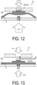
- FIG. 12 is an enlarged cross-sectional view illustrating another example of the operation of the first exhaust valve in the intake state in the first modification. As illustrated in FIG. 12 , even when the air pressure of the first space 52 increases from P0 to P1, if the air pressure P2 in the second space 72B is sufficiently higher than the air pressure P1, the first exhaust valve 60 maintains the closed state.
- FIG. 13 is an enlarged cross-sectional view illustrating an example of the operation of the first exhaust valve in the exhaust state in the first modification.
- the air pressure P21 in the second space 72B is substantially the same as the air pressure P1 in the first space 52. That is, FIG. 13 illustrates a state before the air pressure in the second space 72B is sufficiently reduced as compared with the exhaust state illustrated in FIG. 5 .
- the first exhaust valve 60 since the pressure receiving area S1 of the first exhaust valve 60 with respect to the first space 52 is larger than the pressure receiving area S2 with respect to the second space 72B, the first exhaust valve 60 transitions to the open state before the air pressure P21 of the second space 72B becomes lower than the air pressure P1 of the first space 52. According to such a configuration, the first space 52 can be more quickly shifted to the exhaust state.
- the pressure receiving areas S1 and S2 of the first exhaust valve 60 may be set such that the first exhaust valve 60 can transition to the open state even when the air pressure of the second space is higher than the air pressure P1 of the first space.
- FIG. 14 is an enlarged cross-sectional view illustrating another example of the operation of the first exhaust valve in the exhaust state in a second modification.
- the pressure receiving area S22 in the second modification is smaller than the pressure receiving area S2 in the first modification.
- FIG. 14 illustrates a state such that the exhaust from the first space 52 progresses and the air pressure decreases from P1 to P 11.
- the air pressure in the first space 52 decreases more rapidly than the air pressure in a second space 72C.
- the air pressure P11 of the first space 52 may be lower than the air pressure P22 of the second space 72C.
- the air pressure difference between the first space 52 and the second space required for the first exhaust valve 60 to transition from the open state to the closed state is larger than the air pressure difference in each of the embodiments.
- the volumes of the second spaces 72B and 72C are sufficiently smaller than the volume of the first space 52, the influence on the time lag at the time of pressurizing the second space is small.
Landscapes
- Health & Medical Sciences (AREA)
- Life Sciences & Earth Sciences (AREA)
- Cardiology (AREA)
- Engineering & Computer Science (AREA)
- Vascular Medicine (AREA)
- Biomedical Technology (AREA)
- Veterinary Medicine (AREA)
- Biophysics (AREA)
- Pathology (AREA)
- Physiology (AREA)
- Physics & Mathematics (AREA)
- Heart & Thoracic Surgery (AREA)
- Medical Informatics (AREA)
- Molecular Biology (AREA)
- Surgery (AREA)
- Animal Behavior & Ethology (AREA)
- General Health & Medical Sciences (AREA)
- Public Health (AREA)
- Ophthalmology & Optometry (AREA)
- Mechanical Engineering (AREA)
- General Engineering & Computer Science (AREA)
- Measuring Pulse, Heart Rate, Blood Pressure Or Blood Flow (AREA)
Abstract
Description
- The present invention relates to a measuring device.
- In measuring devices such as a blood pressure monitor, a so-called pressure rising type measuring device is known, the pressure rising type measuring device measuring blood pressure during pressurization, not in a depressurization process after pressurization. In the pressure rising type measuring device, it is required to rapidly exhaust air pressurized in a cuff when the pressurization is stopped. For example, a measuring device using a solenoid valve for rapidly exhausting pressurized air is known.
- Patent Document 1:
JP 2018-171311 A - Providing a solenoid valve complicates a structure of the measuring device, increases a manufacturing cost and power consumption, and hinders miniaturization of the measuring device.
- In one aspect, an object is to provide a measuring device capable of simplifying a structure.
- In one aspect, a measuring device includes a first space for pressurizing a pressurization target and a second space independent of the first space. The measuring device includes a first exhaust valve configured to close or open a communication port communicating the first space with another space. An open/closed state of the first exhaust valve changes in accordance with a pressure difference between the first space and the second space.
- According to one aspect, the structure of the measuring device can be simplified.
-
-
FIG. 1 is a perspective view illustrating an example of an overall configuration of a measuring device according to an embodiment. -
FIG. 2 is a cross-sectional view illustrating an example of a pump in a first embodiment. -
FIG. 3 is a cross-sectional view illustrating an example of a pressure regulating mechanism in the first embodiment. -
FIG. 4 is a cross-sectional view illustrating an example of an intake state in the pressure regulating mechanism in the first embodiment. -
FIG. 5 is a cross-sectional view illustrating an example of an exhaust state of the pressure regulating mechanism in the first embodiment. -
FIG. 6 is a cross-sectional view illustrating an example of a pump according to a second embodiment. -
FIG. 7 is a cross-sectional view illustrating an example of a pressure regulating mechanism in the second embodiment. -
FIG. 8 is a cross-sectional view illustrating an example of an intake state in the pressure regulating mechanism in the second embodiment. -
FIG. 9 is a cross-sectional view illustrating an example of an exhaust state of the pressure regulating mechanism in the second embodiment. -
FIG. 10 is an enlarged cross-sectional view illustrating an example of a positional relationship between a first exhaust valve and an opening in a first modification. -
FIG. 11 is an enlarged cross-sectional view illustrating an example of the operation of the first exhaust valve in the intake state according to the first modification. -
FIG. 12 is an enlarged cross-sectional view illustrating another example of the operation of the first exhaust valve in the intake state according to the first modification. -
FIG. 13 is an enlarged cross-sectional view illustrating an example of the operation of the first exhaust valve in the exhaust state according to the first modification. -
FIG. 14 is an enlarged cross-sectional view illustrating another example of the operation of the first exhaust valve in the exhaust state in a second modification. - Hereinafter, an embodiment of a measuring device disclosed in the present application will be described in detail with reference to the drawings. Note that in the drawings, the dimensional relationship of elements and the ratio of the elements may differ from reality. Among the drawings, parts having mutually different dimensional relationships and proportions may be included. In each of the following embodiments and modifications, the same parts as those illustrated in the drawings described above are denoted by the same reference numerals, and redundant description will be omitted.
- First, a measuring device according to each embodiment will be described with reference to
FIG. 1. FIG. 1 is a perspective view illustrating an example of an overall configuration of a measuring device according to an embodiment. As illustrated inFIG. 1 , ameasuring device 1 in each embodiment is, for example, an electronic blood pressure monitor, and includes acuff 2, amain body 3, and a tube 4 connecting thecuff 2 and themain body 3. Themain body 3 includes apump unit 5 and acontrol unit 6. Thecuff 2 is an example of a pressurization target. - The
pump unit 5 of themain body 3 supplies a fluid to thecuff 2 via the tube 4. In each embodiment, for example, air is supplied as the fluid. Thecontrol unit 6 of themain body 3 controls, for example, start and stop of thepump unit 5. - The
cuff 2 is attached to a measurement site such as a wrist of a subject, for example. Thecuff 2 pressurizes the measurement site with air supplied from themain body 3. In each of the embodiments, the air supplied to thecuff 2 is not exhausted except from the tube 4. The air supplied to thecuff 2 is exhausted through the tube 4 in accordance with the operation of thepump unit 5 described below. - Next, the pump in the first embodiment will be described.
FIG. 2 is a cross-sectional view illustrating an example of the pump according to the first embodiment. As illustrated inFIG. 2 , thepump unit 5 includes adrive mechanism 80, aswing mechanism 90, a pair ofpressure regulating mechanisms discharge ports pump unit 5 is not limited to two, and may be one or three or more. Hereinafter, the pair ofpressure regulating mechanisms mechanism 10 when thepressure regulating mechanisms discharge ports discharge port 59 when thedischarge ports - The
drive mechanism 80 is an operation unit swinging theswing mechanism 90, and includes, for example, a pair ofactuators drive mechanism 80 starts or stops the operation based on a control signal transmitted from thecontrol unit 6. Theactuators - The
swing mechanism 90 illustrated inFIG. 2 includes, for example, ashaft 91 and aswing body 92. Theswing body 92 swings in the vertical direction in the drawing with theshaft 91 as a swing axis, thereby pressing a pressing portion of thepressure regulating mechanism 10 described below. - The pressure regulating
mechanism 10 pressurizes thecuff 2 by supplying air to thecuff 2 via thedischarge port 59 and the tube 4, and depressurizes thecuff 2 by exhausting the air supplied to thecuff 2. The pair ofpressure regulating mechanisms cuff 2 via the tube 4. -
FIG. 3 is a cross-sectional view illustrating an example of the pressure regulating mechanism in the first embodiment. Note thatFIG. 3 illustrates a state where neither pressurization nor depressurization is performed. As illustrated inFIG. 3 , thepressure regulating mechanism 10 according to the first embodiment includes first pressurizingunits first space 52, afirst exhaust valve 60, and apressure regulating unit 70. The twofirst pressurizing units first space 52. - As illustrated in
FIG. 3 , thefirst pressurizing unit 20 includes amovable portion 21, a sealedspace 22, pressingportions intake port 25, anintake valve 26, and athird exhaust valve 27. Themovable portion 21 constitutes a part of the sealedspace 22. Themovable portion 21 changes the volume of the sealedspace 22 by changing the position and inclination in conjunction with thepressing portions movable portion 21 is a diaphragm formed of a material having flexibility such as rubber. - The sealed
space 22 repeats intake and exhaust in accordance with increase and decrease of the volume. When the volume of the sealedspace 22 increases, air is supplied to the sealedspace 22 via theintake port 25 and theintake valve 26. When the volume of the sealedspace 22 decreases, air is supplied to thefirst space 52 via thethird exhaust valve 27. - The
pressing portions movable portion 21 in conjunction with theswing body 92. For example, when theswing body 92 illustrated inFIG. 2 swings in the direction indicated by the arrow D1, thepressing portions movable portion 21 of thefirst pressurizing unit 20. As a result, the volume of the sealedspace 22 decreases. When theswing body 92 illustrated inFIG. 2 swings in the direction indicated by the arrow D2, air is supplied to the sealedspace 22 of thefirst pressurizing unit 20 via theintake port 25 and theintake valve 26. Accordingly, thepressing portions movable portion 21. - The
intake port 25 connects the sealedspace 22 to another space such as the outside of the device. Theintake valve 26 is, for example, a check valve. Theintake valve 26 allows a flow of air from theintake port 25 to the sealedspace 22, and restricts a flow of air from the sealedspace 22 to theintake port 25. Thethird exhaust valve 27 is provided between the sealedspace 22 and thefirst space 52. Thethird exhaust valve 27 is also, for example, a check valve. Thethird exhaust valve 27 allows a flow of air from the sealedspace 22 to thefirst space 52 and restricts a flow of air from thefirst space 52 to the sealedspace 22. By theintake valve 26 and thethird exhaust valve 27, air is supplied from the other space to thefirst space 52 via the sealedspace 22. - As illustrated in
FIG. 3 , thefirst pressurizing unit 30 further includes asecond exhaust valve 38 in addition to themovable portion 21, the sealedspace 22, thepressing portions intake port 25, theintake valve 26, and thethird exhaust valve 27. Similarly to thethird exhaust valve 27 of thefirst pressurizing unit 20, thethird exhaust valve 27 of thefirst pressurizing unit 30 is also provided between the sealedspace 22 of thefirst pressurizing unit 30 and thefirst space 52. - In addition, the
second exhaust valve 38 is provided between the sealedspace 22 and asecond space 72 of thepressure regulating unit 70 to be described below. Thesecond exhaust valve 38 is also, for example, a check valve. Thesecond exhaust valve 38 allows a flow of air from the sealedspace 22 to thesecond space 72, and restricts a flow of air from thesecond space 72 to the sealedspace 22. Thus, thefirst pressurizing unit 30 supplies air to thefirst space 52, and also supplies air to thesecond space 72. - As illustrated in
FIG. 3 , thefirst pressurizing unit 30 and thefirst pressurizing unit 20 in the first embodiment are disposed at positions facing each other, across theshaft 91, in the direction in which theswing body 92 extends. That is, when theswing body 92 illustrated inFIG. 2 swings in the direction indicated by the arrow D1, air is supplied to the sealedspace 22 of thefirst pressurizing unit 20, while air is supplied from the sealedspace 22 of thefirst pressurizing unit 30 to thefirst space 52. Conversely, when theswing body 92 illustrated inFIG. 2 swings in the direction indicated by the arrow D2, air is supplied from the sealedspace 22 of thefirst pressurizing unit 20 to thefirst space 52, while air is supplied to the sealedspace 22 of thefirst pressurizing unit 30. Thus, air is continuously supplied from thefirst pressurizing units first space 52. - The
discharge port 59 connects thefirst space 52 and the tube 4. The pair ofdischarge ports pressure regulating mechanisms first space 52 in thepressure regulating mechanism 11 is connected to thecuff 2 via thedischarge port 57 and the tube 4. Similarly, thefirst space 52 in thepressure regulating mechanism 12 is connected to thecuff 2 via thedischarge port 58 and the tube 4. As a result, air is supplied to thecuff 2 from both of the pair ofpressure regulating mechanisms - In the first embodiment, air is supplied to the
first space 52 of thepressure regulating mechanism 10 from thefirst pressurizing unit 20 and thefirst pressurizing unit 30. In the first embodiment, thefirst space 52 and thecuff 2 constitute a sealed space when thefirst exhaust valve 60 described below is in a closed state. In this case, the air supplied to thefirst space 52 is supplied to thecuff 2 via thedischarge port 59 and the tube 4, thereby pressurizing thecuff 2. - On the other hand, when the
first exhaust valve 60 is in an open state, the air in thefirst space 52 is exhausted from thefirst exhaust valve 60 to the other space. At this time, air is also exhausted via thefirst exhaust valve 60 from thecuff 2 connected via thedischarge port 59 and the tube 4. In the first embodiment, the air pressure in thefirst space 52 and thecuff 2 increases according to the pressurization by thefirst pressurizing unit 20 and thefirst pressurizing unit 30, with the air pressure in the other space as the lower limit. Hereinafter, thefirst exhaust valve 60 in the closed state may be referred to as afirst exhaust valve 60c, and thefirst exhaust valve 60 in the open state may be referred to as a first exhaust valve 60o. - The
pressure regulating unit 70 illustrated inFIG. 3 includes thesecond space 72 and anair leakage valve 79. Thesecond space 72 is a space independent of thefirst space 52. Thesecond space 72 is not a sealed space, but communicates with the other space via theair leakage valve 79, and air constantly leaks to the other space. - In the first embodiment, air is supplied to the
second space 72 from thefirst pressurizing unit 30 illustrated inFIG. 3 via thesecond exhaust valve 38. Further, the amount of air supplied by thefirst pressurizing unit 30 is larger than the amount of air leaking from theair leakage valve 79. That is, in the first embodiment, the air pressure in thesecond space 72 increases according to the pressurization by thefirst pressurizing unit 30 with the air pressure in the other space as a lower limit. In this case, as will be described below, thesecond space 72 is pressurized by thefirst pressurizing unit 30, so that the air pressure inside thesecond space 72 becomes higher than the air pressure inside thefirst space 52. - Further, in the first embodiment, when the pressurization by the
first pressurizing unit 30 is stopped, the air supplied into thesecond space 72 leaks from theair leakage valve 79 to the other space. As a result, the air pressure in thesecond space 72 rapidly approaches the air pressure in the other space. As a result, as will be described below, the air pressure inside thesecond space 72 becomes lower than the air pressure inside thefirst space 52. - The
first exhaust valve 60 closes or opens thefirst space 52 and the other space such as the outside of the device. Thefirst exhaust valve 60 is provided, for example, between thefirst space 52 and thesecond space 72. Thefirst exhaust valve 60 is, for example, a check valve, and regulates the flow of air from the other space to thefirst space 52 and the flow of air from thesecond space 72 to the other space. For example, as illustrated inFIG. 3 , thefirst exhaust valve 60 includes afirst surface 61 facing thefirst space 52 and asecond surface 62 facing thesecond space 72. Thefirst exhaust valve 60 in the embodiment is, for example, a rapid exhaust valve. In the first embodiment, the pressure receiving area S1 of thefirst surface 61 with respect to thefirst space 52 and the pressure receiving area S1 with respect to thesecond space 72 are substantially the same. - In the first embodiment, for example, the open/closed state of the
first exhaust valve 60 changes according to the air pressure difference (differential pressure) between thefirst space 52 and thesecond space 72. Thefirst exhaust valve 60 changes between the open state 60o and theclosed state 60c by, for example, changing position or changing shape, such as the size of an opening, in accordance with the differential pressure between thefirst space 52 and thesecond space 72. - For example, the
first exhaust valve 60 is in the closed state when the air pressure in thesecond space 72 is equal to or higher than the air pressure in thefirst space 52. In this case, since thefirst space 52 is closed with respect to the other space, the air in thefirst space 52 is exhausted from thedischarge port 59 to thecuff 2. - On the other hand, for example, the
first exhaust valve 60 is in the open state when the air pressure in thesecond space 72 is lower than the air pressure in thefirst space 52. In this case, the air in thefirst space 52 is exhausted to the other space via thefirst exhaust valve 60, whereby the air pressure in thefirst space 52 rapidly approaches the air pressure in the other space. Along with this, the air supplied from thefirst space 52 to thecuff 2 is also sucked into thefirst space 52, so the air pressure in thecuff 2 also decreases rapidly. - As illustrated in
FIG. 3 , the volume of thesecond space 72 is much smaller than the volume of thefirst space 52. In this case, for example, when thefirst pressurizing unit 30 pressurizes both thefirst space 52 and thesecond space 72 as illustrated inFIG. 4 , the increase of the air pressure in thesecond space 72 is faster than the increase of the air pressure in thefirst space 52. In this case, as illustrated inFIG. 4 , an intake state such that thefirst exhaust valve 60 is closed is achieved.FIG. 4 is a cross-sectional view illustrating an example of the intake state in the pressure regulating mechanism according to the first embodiment. As illustrated inFIG. 4 , in the intake state, thepressing portions first pressurizing units first space 52 as indicated by arrows A1 and A3. Similarly, as indicated by the arrow A2, air is also supplied from thefirst pressurizing unit 30 to thesecond space 72. - In this case, the amount of air illustrated by the arrow A2 supplied to the
second space 72 is larger than the amount of air illustrated by the arrow L1 leaking from theair leakage valve 79. The volume of thesecond space 72 is much smaller than the volume of thefirst space 52. For this reason, when thefirst pressurizing unit 30 starts pressurization, the air pressure P2 in thesecond space 72 rapidly increases compared to the increase in the air pressure P1 in thefirst space 52. As a result, the air pressure P2 in thesecond space 72 becomes higher than the air pressure P1 in thefirst space 52. As a result, since a differential pressure is generated between thefirst space 52 and thesecond space 72, thefirst exhaust valve 60 is closed. - On the other hand, when the pressurization by the
first pressurizing unit 30 is stopped, the supply of air to thesecond space 72 indicated by the arrow A2 is stopped. In this case, as illustrated inFIG. 5 , an exhaust state such that thefirst exhaust valve 60 is opened is achieved.FIG. 5 is a cross-sectional view illustrating an example of the exhaust state of the pressure regulating mechanism in the first embodiment. As illustrated inFIG. 5 , while air continues to leak from thesecond space 72 via theair leakage valve 79 as illustrated by the arrow L1', the air pressure P 1' in thefirst space 52 is high until thefirst exhaust valve 60 is opened. Since the volume of thesecond space 72 is small, the air pressure in thesecond space 72 rapidly decreases due to the leaking air indicated by the arrow L1'. - As a result, the air pressure in the
second space 72 becomes lower than the air pressure in thefirst space 52. As a result, the closedfirst exhaust valve 60 is opened, and thefirst space 52 is in the exhaust state. In this case, a gap G is formed by opening thefirst exhaust valve 60, and the air in thefirst space 52 is exhausted from the gap G to the other space by the differential pressure. This makes it possible to rapidly decrease the air pressure in thefirst space 52 and thecuff 2. The gap G is an example of a communication port. - As described above, the measuring
device 1 according to the first embodiment includes thefirst space 52 for pressurizing thepressurization target 2 and thesecond space 72 independent of thefirst space 52. The measuringdevice 1 includes thefirst exhaust valve 60 closing or opening the communication port G communicating thefirst space 52 with the other space. The open/closed state of thefirst exhaust valve 60 changes according to the pressure difference between thefirst space 52 and thesecond space 72. Further, in the first embodiment, thefirst space 52 is pressurized by the plurality offirst pressurizing units second space 72 is pressurized by thefirst pressurizing unit 30. In such a configuration, the differential pressure between thefirst space 52 and thesecond space 72 can be generated with a simple structure without largely changing the configuration of the existing pump. As a result, the structure of the pressure rising type measuring device can be simplified. - In the first embodiment, a configuration has been described such that the
first pressurizing unit 30 pressurizing thefirst space 52 also supplies air to thesecond space 72, but the embodiment is not limited to this. For example, the second space may be pressurized by another pressurizing unit different from the first pressurizing unit. - A measuring device 1A according to the second embodiment has the same appearance as the appearance of the measuring
device 1 illustrated inFIG. 1 except that thepump unit 5 is changed to apump unit 5A, and therefore, the illustration is omitted.FIG. 6 is a cross-sectional view illustrating an example of a pump according to the second embodiment. As illustrated inFIG. 6 , thepump unit 5A in the second embodiment includes thedrive mechanism 80, theswing mechanism 90,pressure regulating mechanisms discharge ports pressure regulating mechanisms pressure regulating mechanism 10A when thepressure regulating mechanisms -
FIG. 7 is a cross-sectional view illustrating an example of the pressure regulating mechanism in the second embodiment. As illustrated inFIG. 7 , thepressure regulating mechanism 10A in the second embodiment includes twofirst pressurizing units second pressurizing unit 40, thefirst space 52, thefirst exhaust valve 60, and apressure regulating unit 70A. Similarly to thefirst pressurizing units first pressurizing units shaft 91 illustrated inFIG. 6 , in the direction in which theswing body 92 extends. Thefirst pressurizing units first pressurizing unit 20 in the first embodiment, and thus detailed description will be omitted. - The
second pressurizing unit 40 does not supply air to thefirst space 52, but supplies air to thesecond space 72A of thepressure regulating unit 70A illustrated inFIG. 7 . Thesecond pressurizing unit 40 includes amovable portion 41, a sealedspace 42, pressingportions intake port 45, anintake valve 46, and afourth exhaust valve 48. - Similarly to the
movable portion 21 and the sealedspace 22 of the first pressurizing unit, themovable portion 41 and the sealedspace 42 of thesecond pressurizing unit 40 repeat intake and exhaust in accordance with the up and down movement of thepressing portions second pressurizing unit 40 supplies the air supplied from theintake port 45 via theintake valve 46 to thesecond space 72A via thefourth exhaust valve 48. Theintake valve 46 is also, for example, a check valve similar to theintake valve 26. - The
fourth exhaust valve 48 is provided between the sealedspace 42 and thesecond space 72A. Thefourth exhaust valve 48 is also, for example, a check valve. Thefourth exhaust valve 48 allows a flow of air from the sealedspace 22 to thesecond space 72, and restricts a flow of air from thesecond space 72 to the sealedspace 22. As a result, thesecond pressurizing unit 40 supplies air to thesecond space 72A without supplying air to thefirst space 52. - The
pressure regulating unit 70A illustrated inFIG. 7 includes thesecond space 72A and anair leakage valve 79A. Thesecond space 72A is a space independent of thefirst space 52. Thesecond space 72A is not a sealed space, and air constantly leaks to the other space via theair leakage valve 79A. Since the structure of thepressure regulating unit 70A is the same as the structure of thepressure regulating unit 70 in the first embodiment except that thepressure regulating unit 70A is connected to thesecond pressurizing unit 40 instead of thefirst pressurizing unit 30, the detailed description will be omitted. - The
second pressurizing unit 40 in the second embodiment may have the same configuration as thefirst pressurizing unit 20, but in view of the ratio of the volumes of thesecond space 72A and thefirst space 52, for example, the volume of the sealed space or the displacement of the movable wall of thesecond pressurizing unit 40 may be smaller than the volume or the displacement of thefirst pressurizing unit 20, or the number of thesecond pressurizing unit 40 may be smaller than the number of thefirst pressurizing unit 20. For example, in the second embodiment, as illustrated inFIGS. 6 and7 , twosecond pressurizing units 40 are provided for fourfirst pressurizing units 20 in thepump unit 5A. In the example illustrated inFIG. 7 , thesecond pressurizing unit 40 and thepressure regulating unit 70A are disposed between the twofirst pressurizing units swing body 92 extends, but the positions where thesecond pressurizing unit 40 and thepressure regulating unit 70A are disposed are not limited to this. - The
first exhaust valve 60A in the second embodiment is provided between thefirst space 52 and thesecond space 72A. Similarly to thefirst exhaust valve 60, for example, the open/closed state of thefirst exhaust valve 60A changes according to the air pressure difference (differential pressure) between thefirst space 52 and thesecond space 72. - The intake state and the exhaust state in the second embodiment will be described with reference to
FIGS. 8 and9 .FIG. 8 is a cross-sectional view illustrating an example of an intake state in the pressure regulating mechanism according to the second embodiment. As illustrated inFIG. 8 , in the intake state, the amount of the air A4 supplied from thesecond pressurizing unit 40 to thesecond space 72A is larger than the amount of the air L2 leaking from theair leakage valve 79. In this case, when thesecond pressurizing unit 40 starts pressurization, the air pressure P4 in thesecond space 72 rapidly increases compared to the increase in the air pressure P3 in thefirst space 52. As a result, since a differential pressure is generated between thefirst space 52 and thesecond space 72A, thefirst exhaust valve 60A is closed. - On the other hand, when the pressurization by the
second pressurizing unit 40 is stopped, the supply of air to thesecond space 72A is stopped.FIG. 9 is a cross-sectional view illustrating an example of an exhaust state of the pressure regulating mechanism in the second embodiment. As illustrated inFIG. 9 , while air continues to leak from thesecond space 72A via theair leakage valve 79A as illustrated by the arrow L2', the air pressure P3' in thefirst space 52 is high until thefirst exhaust valve 60A is opened. As a result, the air pressure in thesecond space 72A becomes lower than the air pressure in thefirst space 52. As a result, a gap G is formed by opening the closedfirst exhaust valve 60, and the air in thefirst space 52 is exhausted from the gap G to the other space by the differential pressure. - As described above, the measuring device 1A in the second embodiment includes the
first pressurizing units first space 52 and thesecond pressurizing unit 40 pressurizing thesecond space 72. According to such a configuration, it is possible to easily generate a differential pressure between thefirst space 52 and thesecond space 72A by thesecond pressurizing unit 40 pressurizing only thesecond space 72A. - The configuration of each of the embodiments has been described above, but the embodiments are not limited to these configurations. For example, a plurality of the
second spaces 72 may be provided for onefirst space 52, and a plurality of the pressurizing units pressurizing thesecond spaces 72 may be provided. For example, two or morefirst pressurizing units 30 or two or moresecond pressurizing units 40 may be provided, or both thefirst pressurizing unit 30 and thesecond pressurizing unit 40 may be provided. - In addition, although a configuration such that the
air leakage valve 79 is provided in the pressure regulating unit has been described, the present invention is not limited to this configuration as long as the air in thesecond space 72 can be constantly leaked to the other space. For example, the surface of thesecond space 72 may be roughened or grooved, or fine holes may be provided in thesecond space 72. Further, a configuration such that air leaks from thesecond exhaust valve 38 or thefourth exhaust valve 48 may be adopted. - In addition, for example, the flow path load from the
first pressurizing unit first space 52 may be larger than the flow path load from thefirst pressurizing unit 30 to thesecond space 72 or the flow path load from thesecond pressurizing unit 40 to thesecond space 72A. Accordingly, even when there is no volume difference between the first space and the second space, a differential pressure between the first space and the second space can be generated. In order to change the flow path load, for example, the hardness of the valve may be changed between thethird exhaust valve 27 and thesecond exhaust valve 38 or thefourth exhaust valve 48, or the length or thickness of the flow path may be changed between the flow path to thefirst space 52 and the flow path to thesecond space 72. In addition, it is possible to more easily generate the differential pressure by combining the difference in the flow path load and the difference in the volume. - Further, a configuration such that the first exhaust valve is in the open state may be adopted even in a state such that the differential pressure is small or in a state such that no differential pressure is generated. For example, in the first embodiment, the pressure receiving area of the
first surface 61 of thefirst exhaust valve 60 facing thefirst space 52 may be different from the pressure receiving area of thesecond surface 62 of thefirst exhaust valve 60 facing thesecond space 72.FIG. 10 is an enlarged cross-sectional view illustrating an example of the positional relationship between the first exhaust valve and an opening in a first modification. Although the following description will be made based on the configuration of the first embodiment, each modification can also be applied to thefirst exhaust valve 60A, thefirst space 52, and thesecond space 72A in the second embodiment. - As illustrated in
FIG. 10 , thefirst surface 61 of thefirst exhaust valve 60 faces thefirst space 52 via anopening 65. Further, thesecond surface 62 of thefirst exhaust valve 60 faces asecond space 72B via theopening 67. In the first modification, the area S2 of theopening 67, that is, the pressure receiving area of thesecond surface 62 with respect to thesecond space 72B, is smaller than the area S1 of theopening 65, that is, the pressure receiving area of thefirst surface 61 with respect to thefirst space 52.FIG. 10 illustrates a state such that thefirst space 52 and thesecond space 72B are neither pressurized nor depressurized. In such a state, the air pressure P0 in thefirst space 52 and thesecond space 72B is substantially the same as the air pressure in the other space. - Operations during pressurization and depressurization in such a configuration will be described with reference to
FIGS. 11 to 13 .FIG. 11 is an enlarged cross-sectional view illustrating an example of the operation of the first exhaust valve in the intake state in the first modification. As illustrated inFIG. 11 , when the air pressure P20 in thesecond space 72B becomes sufficiently higher than the air pressure P0 in thefirst space 52, thefirst exhaust valve 60 is in the closed state. Then, when thefirst space 52 is closed by thefirst exhaust valve 60c in the closed state, air is supplied from thefirst pressurizing units first space 52, so that the air pressure in thefirst space 52 also increases. -
FIG. 12 is an enlarged cross-sectional view illustrating another example of the operation of the first exhaust valve in the intake state in the first modification. As illustrated inFIG. 12 , even when the air pressure of thefirst space 52 increases from P0 to P1, if the air pressure P2 in thesecond space 72B is sufficiently higher than the air pressure P1, thefirst exhaust valve 60 maintains the closed state. - Next, when the supply of air by the
first pressurizing units second space 72B rapidly decreases due to air leakage from theair leakage valve 79 illustrated inFIG. 3 . On the other hand, since thefirst exhaust valve 60 is in the closed state, the air pressure P1 of thefirst space 52 does not immediately decrease even when the supply of air is stopped. Accordingly, as illustrated inFIG. 13 , thefirst exhaust valve 60 transitions to the open state in accordance with the difference between the air pressure P1 of thefirst space 52 and the air pressure P21 of thesecond space 72B. As a result, the air in thefirst space 52 is exhausted to the other space.FIG. 13 is an enlarged cross-sectional view illustrating an example of the operation of the first exhaust valve in the exhaust state in the first modification. InFIG. 13 , the air pressure P21 in thesecond space 72B is substantially the same as the air pressure P1 in thefirst space 52. That is,FIG. 13 illustrates a state before the air pressure in thesecond space 72B is sufficiently reduced as compared with the exhaust state illustrated inFIG. 5 . - In the first modification, since the pressure receiving area S1 of the
first exhaust valve 60 with respect to thefirst space 52 is larger than the pressure receiving area S2 with respect to thesecond space 72B, thefirst exhaust valve 60 transitions to the open state before the air pressure P21 of thesecond space 72B becomes lower than the air pressure P1 of thefirst space 52. According to such a configuration, thefirst space 52 can be more quickly shifted to the exhaust state. - For example, the pressure receiving areas S1 and S2 of the
first exhaust valve 60 may be set such that thefirst exhaust valve 60 can transition to the open state even when the air pressure of the second space is higher than the air pressure P1 of the first space. In such a configuration, it is possible to transition to the exhaust state more quickly than in the first modification, and it is possible to stably continue the exhaust state without thefirst exhaust valve 60 returning to the closed state even in a case where the decrease in the air pressure of the second space is gradual in the exhaust state. -
FIG. 14 is an enlarged cross-sectional view illustrating another example of the operation of the first exhaust valve in the exhaust state in a second modification. As illustrated inFIG. 14 , the pressure receiving area S22 in the second modification is smaller than the pressure receiving area S2 in the first modification.FIG. 14 illustrates a state such that the exhaust from thefirst space 52 progresses and the air pressure decreases from P1 toP 11. In the second modification, the air pressure in thefirst space 52 decreases more rapidly than the air pressure in a second space 72C. In this case, as illustrated inFIG. 14 , the air pressure P11 of thefirst space 52 may be lower than the air pressure P22 of the second space 72C. - Even in such a state, in the second modification, due to the difference between the pressure receiving area S1 with respect to the
first space 52 and the pressure receiving area S22 with respect to the second space 72C, thefirst exhaust valve 60 is suppressed from transitioning to the open state or vibrating between the open state and the closed state. Thus, a stable exhaust state can be continued. - In each of the modifications, the air pressure difference between the
first space 52 and the second space required for thefirst exhaust valve 60 to transition from the open state to the closed state is larger than the air pressure difference in each of the embodiments. However, in each of the modifications, since the volumes of thesecond spaces 72B and 72C are sufficiently smaller than the volume of thefirst space 52, the influence on the time lag at the time of pressurizing the second space is small. - The embodiment and the modifications of the present invention have been described, but the present invention is not limited to the embodiment and the modifications but can be variously modified without departing from the spirit of the present invention. Various modifications within a scope not departing from the gist are included in the technical scope of the present invention, and this is obvious to a person having skill in the art from the description of the claims.
- 1, 1A Measuring device (blood pressure monitor), 2 Cuff, 3 Main body, 4 Tube, 5, 5A Pump unit, 6 Control unit, 10, 10A (11 to 14) Pressure regulating mechanism, 20, 20a, 20b, 30 First pressurizing unit, 21, 41 Movable portion, 22, 42 Sealed space, 23, 24, 43, 44 Pressing portion, 25, 45 Intake port, 26, 46 Intake valve, 27 Third exhaust valve, 38 Second exhaust valve, 40 Second pressurizing unit, 48 Fourth exhaust valve, 52 First space, 57, 58, 59 Discharge port, 60, 60A First exhaust valve, 70, 70A Pressure regulating unit, 72, 72A, 72B, 72C Second space, 79, 79A Air leakage valve, 80 Drive mechanism, 81, 82 Actuator, 90 Swing mechanism, 91 Shaft, 92 Swing body
Claims (9)
- A measuring device comprising:a first space for pressurizing a pressurization target;a second space independent of the first space; anda first exhaust valve configured to close or open a communication port communicating the first space with another space, whereinan open/closed state of the first exhaust valve changes in accordance with a pressure difference between the first space and the second space.
- The measuring device according to claim 1, whereinwhen a pressure in the first space is lower than a pressure in the second space, the first exhaust valve is closed and the first space pressurizes the pressurization target, andwhen the pressure in the first space is equal to or higher than the pressure in the second space, the first exhaust valve is opened to reduce the pressure in the first space.
- The measuring device according to claim 1 or 2, wherein
a volume of the first space is larger than a volume of the second space. - The measuring device according to claim 1 or 2, wherein
a flow path load of a suction port of the first space is larger than a flow path load of a suction port of the second space. - The measuring device according to any one of claims 1 to 4, further comprising:a second exhaust valve provided in the suction port to the second space; andan air leakage valve configured to communicate the second space with another space.
- The measuring device according to any one of claims 1 to 5, further comprising a first pressurizing unit configured to pressurize the first space and the second space.
- The measuring device according to claim 6, whereinthe first space is pressurized by a plurality of the first pressurizing units, andthe second space is pressurized by at least one of the first pressurizing units.
- The measuring device according to any one of claims 1 to 5, further comprising:a first pressurizing unit configured to pressurize the first space; anda second pressurizing unit configured to pressurize the second space.
- The measuring device according to any one of claims 1 to 8, whereinthe first exhaust valve includes a first surface facing the first space and a second surface facing the second space, anda pressure receiving area of the first surface is larger than a pressure receiving area of the second surface.
Applications Claiming Priority (2)
| Application Number | Priority Date | Filing Date | Title |
|---|---|---|---|
| JP2021022108 | 2021-02-15 | ||
| PCT/JP2022/005863 WO2022173053A1 (en) | 2021-02-15 | 2022-02-15 | Measuring device |
Publications (2)
| Publication Number | Publication Date |
|---|---|
| EP4293261A1 true EP4293261A1 (en) | 2023-12-20 |
| EP4293261A4 EP4293261A4 (en) | 2025-01-22 |
Family
ID=82838382
Family Applications (1)
| Application Number | Title | Priority Date | Filing Date |
|---|---|---|---|
| EP22752875.9A Pending EP4293261A4 (en) | 2021-02-15 | 2022-02-15 | MEASURING DEVICE |
Country Status (5)
| Country | Link |
|---|---|
| US (1) | US20240115146A1 (en) |
| EP (1) | EP4293261A4 (en) |
| JP (1) | JPWO2022173053A1 (en) |
| CN (1) | CN116916818A (en) |
| WO (1) | WO2022173053A1 (en) |
Family Cites Families (9)
| Publication number | Priority date | Publication date | Assignee | Title |
|---|---|---|---|---|
| JPS61257625A (en) * | 1985-05-13 | 1986-11-15 | 株式会社エー・アンド・ディ | Constant speed exhaust apparatus for hemomanometer |
| JPH02154739A (en) * | 1988-12-08 | 1990-06-14 | Ouken Seiko Kk | Automatic blood pressure measuring instrument |
| JPH02154738A (en) * | 1988-12-08 | 1990-06-14 | Ouken Seiko Kk | Automatic blood pressure measuring instrument |
| JP5185475B2 (en) * | 2011-04-11 | 2013-04-17 | 株式会社村田製作所 | Valve, fluid control device |
| JP5668582B2 (en) * | 2011-04-11 | 2015-02-12 | 株式会社村田製作所 | Fluid control device |
| JP5735690B1 (en) * | 2014-08-15 | 2015-06-17 | 応研精工株式会社 | Quick drain valve integrated diaphragm pump |
| CN104825145A (en) * | 2015-04-30 | 2015-08-12 | 深圳金亿帝医疗设备股份有限公司 | Air valve, integrated air pump and wearable electronic sphygmomanometer |
| JP6324574B1 (en) | 2017-03-31 | 2018-05-16 | シチズン時計株式会社 | Sphygmomanometer |
| JP6913366B2 (en) * | 2017-09-27 | 2021-08-04 | 応研精工株式会社 | Diaphragm pump with integrated rapid exhaust valve |
-
2022
- 2022-02-15 CN CN202280014592.5A patent/CN116916818A/en active Pending
- 2022-02-15 US US18/546,162 patent/US20240115146A1/en active Pending
- 2022-02-15 WO PCT/JP2022/005863 patent/WO2022173053A1/en not_active Ceased
- 2022-02-15 EP EP22752875.9A patent/EP4293261A4/en active Pending
- 2022-02-15 JP JP2022580716A patent/JPWO2022173053A1/ja active Pending
Also Published As
| Publication number | Publication date |
|---|---|
| CN116916818A (en) | 2023-10-20 |
| WO2022173053A1 (en) | 2022-08-18 |
| US20240115146A1 (en) | 2024-04-11 |
| EP4293261A4 (en) | 2025-01-22 |
| JPWO2022173053A1 (en) | 2022-08-18 |
Similar Documents
| Publication | Publication Date | Title |
|---|---|---|
| US8905940B2 (en) | Flow rate control valve and blood pressure information measurement device including the same | |
| JP5030242B2 (en) | Bellows pump and operation method of bellows pump | |
| US11293427B2 (en) | Valve, and fluid control device including valve | |
| US20120298233A1 (en) | Microfluidic component for manipulating a fluid, and microfluidic chip | |
| US10688228B2 (en) | Suction device | |
| CN117280149A (en) | Valves, fluid control devices, pressurization devices, and blood pressure monitors | |
| US20240115146A1 (en) | Measuring device | |
| JP3859221B2 (en) | Open / close control valve for pneumatic drive | |
| CN211598919U (en) | Variable motor self-feedback controller and hydraulic system | |
| CN101263307B (en) | Servo-controlled metering poppet valve | |
| JP2017219136A (en) | Flow control valve, its process of manufacture and blood pressure information measurement device | |
| JP2006046284A (en) | Chemical liquid supply system and chemical liquid supply pump | |
| CN114459677A (en) | Liquid pressure control method for liquid pressure checking device | |
| EP4471278A1 (en) | Liquid pressure calibration apparatus | |
| WO2017208684A1 (en) | Flow control valve and blood pressure information measurement device | |
| CN118902422A (en) | Piezoelectric micropump type automatic sphygmomanometer for realizing pressurization and pressure relief by utilizing single barb valve | |
| KR20210083162A (en) | Actuator control apparatus | |
| CN114483695A (en) | Liquid pressure calibration device | |
| JPWO2018221286A1 (en) | Pressure control device and pressure utilizing device | |
| EP4348062B1 (en) | Pressure multiplier | |
| JP4088963B2 (en) | Pressure amplifier | |
| CN110714507A (en) | Valve structure and construction machine | |
| JP2001140752A (en) | Fluid pressure driven pump | |
| CN111365518B (en) | Pilot-operated proportional flow valve with flow feedback function | |
| JPH10252705A (en) | Pressure oil supply device |
Legal Events
| Date | Code | Title | Description |
|---|---|---|---|
| STAA | Information on the status of an ep patent application or granted ep patent |
Free format text: STATUS: THE INTERNATIONAL PUBLICATION HAS BEEN MADE |
|
| PUAI | Public reference made under article 153(3) epc to a published international application that has entered the european phase |
Free format text: ORIGINAL CODE: 0009012 |
|
| STAA | Information on the status of an ep patent application or granted ep patent |
Free format text: STATUS: REQUEST FOR EXAMINATION WAS MADE |
|
| 17P | Request for examination filed |
Effective date: 20230912 |
|
| AK | Designated contracting states |
Kind code of ref document: A1 Designated state(s): AL AT BE BG CH CY CZ DE DK EE ES FI FR GB GR HR HU IE IS IT LI LT LU LV MC MK MT NL NO PL PT RO RS SE SI SK SM TR |
|
| DAV | Request for validation of the european patent (deleted) | ||
| DAX | Request for extension of the european patent (deleted) | ||
| P01 | Opt-out of the competence of the unified patent court (upc) registered |
Free format text: CASE NUMBER: APP_52552/2024 Effective date: 20240919 |
|
| A4 | Supplementary search report drawn up and despatched |
Effective date: 20241219 |
|
| RIC1 | Information provided on ipc code assigned before grant |
Ipc: F04B 45/04 20060101ALI20241213BHEP Ipc: F04B 45/047 20060101ALI20241213BHEP Ipc: A61B 5/0235 20060101ALI20241213BHEP Ipc: A61B 5/021 20060101ALI20241213BHEP Ipc: A61B 5/0225 20060101ALI20241213BHEP Ipc: F04B 43/04 20060101ALI20241213BHEP Ipc: F16K 31/126 20060101AFI20241213BHEP |
|
| STAA | Information on the status of an ep patent application or granted ep patent |
Free format text: STATUS: EXAMINATION IS IN PROGRESS |