EP4293175A2 - Structure de support d'échafaudage et procédé d'assemblage d'échafaudage - Google Patents
Structure de support d'échafaudage et procédé d'assemblage d'échafaudage Download PDFInfo
- Publication number
- EP4293175A2 EP4293175A2 EP23206919.5A EP23206919A EP4293175A2 EP 4293175 A2 EP4293175 A2 EP 4293175A2 EP 23206919 A EP23206919 A EP 23206919A EP 4293175 A2 EP4293175 A2 EP 4293175A2
- Authority
- EP
- European Patent Office
- Prior art keywords
- vertical support
- support element
- bracket
- framework
- vertical
- Prior art date
- Legal status (The legal status is an assumption and is not a legal conclusion. Google has not performed a legal analysis and makes no representation as to the accuracy of the status listed.)
- Pending
Links
- 238000000034 method Methods 0.000 title claims abstract description 18
- 238000010276 construction Methods 0.000 claims abstract description 36
- 230000009194 climbing Effects 0.000 claims description 7
- XAGFODPZIPBFFR-UHFFFAOYSA-N aluminium Chemical compound [Al] XAGFODPZIPBFFR-UHFFFAOYSA-N 0.000 description 5
- 239000004411 aluminium Substances 0.000 description 5
- 229910052782 aluminium Inorganic materials 0.000 description 5
- 230000007246 mechanism Effects 0.000 description 5
- 238000005304 joining Methods 0.000 description 3
- 229910052751 metal Inorganic materials 0.000 description 3
- 239000002184 metal Substances 0.000 description 3
- 230000003014 reinforcing effect Effects 0.000 description 2
- AZDRQVAHHNSJOQ-UHFFFAOYSA-N alumane Chemical group [AlH3] AZDRQVAHHNSJOQ-UHFFFAOYSA-N 0.000 description 1
- 238000005516 engineering process Methods 0.000 description 1
- 230000014509 gene expression Effects 0.000 description 1
- 230000005484 gravity Effects 0.000 description 1
- 238000004519 manufacturing process Methods 0.000 description 1
- 239000000463 material Substances 0.000 description 1
- 230000002787 reinforcement Effects 0.000 description 1
- 238000009418 renovation Methods 0.000 description 1
- 230000000630 rising effect Effects 0.000 description 1
- 238000003860 storage Methods 0.000 description 1
- 238000003466 welding Methods 0.000 description 1
Images


Classifications
-
- E—FIXED CONSTRUCTIONS
- E04—BUILDING
- E04G—SCAFFOLDING; FORMS; SHUTTERING; BUILDING IMPLEMENTS OR AIDS, OR THEIR USE; HANDLING BUILDING MATERIALS ON THE SITE; REPAIRING, BREAKING-UP OR OTHER WORK ON EXISTING BUILDINGS
- E04G1/00—Scaffolds primarily resting on the ground
- E04G1/38—Scaffolds partly supported by the building
-
- E—FIXED CONSTRUCTIONS
- E04—BUILDING
- E04G—SCAFFOLDING; FORMS; SHUTTERING; BUILDING IMPLEMENTS OR AIDS, OR THEIR USE; HANDLING BUILDING MATERIALS ON THE SITE; REPAIRING, BREAKING-UP OR OTHER WORK ON EXISTING BUILDINGS
- E04G1/00—Scaffolds primarily resting on the ground
- E04G1/15—Scaffolds primarily resting on the ground essentially comprising special means for supporting or forming platforms; Platforms
- E04G1/152—Platforms made of metal or with metal-supporting frame
-
- E—FIXED CONSTRUCTIONS
- E04—BUILDING
- E04G—SCAFFOLDING; FORMS; SHUTTERING; BUILDING IMPLEMENTS OR AIDS, OR THEIR USE; HANDLING BUILDING MATERIALS ON THE SITE; REPAIRING, BREAKING-UP OR OTHER WORK ON EXISTING BUILDINGS
- E04G3/00—Scaffolds essentially supported by building constructions, e.g. adjustable in height
- E04G3/20—Scaffolds essentially supported by building constructions, e.g. adjustable in height supported by walls
-
- E—FIXED CONSTRUCTIONS
- E04—BUILDING
- E04G—SCAFFOLDING; FORMS; SHUTTERING; BUILDING IMPLEMENTS OR AIDS, OR THEIR USE; HANDLING BUILDING MATERIALS ON THE SITE; REPAIRING, BREAKING-UP OR OTHER WORK ON EXISTING BUILDINGS
- E04G3/00—Scaffolds essentially supported by building constructions, e.g. adjustable in height
- E04G3/22—Scaffolds essentially supported by building constructions, e.g. adjustable in height supported by roofs or ceilings
-
- E—FIXED CONSTRUCTIONS
- E04—BUILDING
- E04G—SCAFFOLDING; FORMS; SHUTTERING; BUILDING IMPLEMENTS OR AIDS, OR THEIR USE; HANDLING BUILDING MATERIALS ON THE SITE; REPAIRING, BREAKING-UP OR OTHER WORK ON EXISTING BUILDINGS
- E04G5/00—Component parts or accessories for scaffolds
- E04G5/02—Scaffold feet, e.g. with arrangements for adjustment
-
- E—FIXED CONSTRUCTIONS
- E04—BUILDING
- E04G—SCAFFOLDING; FORMS; SHUTTERING; BUILDING IMPLEMENTS OR AIDS, OR THEIR USE; HANDLING BUILDING MATERIALS ON THE SITE; REPAIRING, BREAKING-UP OR OTHER WORK ON EXISTING BUILDINGS
- E04G5/00—Component parts or accessories for scaffolds
- E04G5/06—Consoles; Brackets
- E04G5/067—Consoles; Brackets specially adapted for attachment to posts
-
- E—FIXED CONSTRUCTIONS
- E04—BUILDING
- E04G—SCAFFOLDING; FORMS; SHUTTERING; BUILDING IMPLEMENTS OR AIDS, OR THEIR USE; HANDLING BUILDING MATERIALS ON THE SITE; REPAIRING, BREAKING-UP OR OTHER WORK ON EXISTING BUILDINGS
- E04G5/00—Component parts or accessories for scaffolds
- E04G5/08—Scaffold boards or planks
-
- E—FIXED CONSTRUCTIONS
- E04—BUILDING
- E04G—SCAFFOLDING; FORMS; SHUTTERING; BUILDING IMPLEMENTS OR AIDS, OR THEIR USE; HANDLING BUILDING MATERIALS ON THE SITE; REPAIRING, BREAKING-UP OR OTHER WORK ON EXISTING BUILDINGS
- E04G5/00—Component parts or accessories for scaffolds
- E04G5/10—Steps or ladders specially adapted for scaffolds
-
- E—FIXED CONSTRUCTIONS
- E04—BUILDING
- E04G—SCAFFOLDING; FORMS; SHUTTERING; BUILDING IMPLEMENTS OR AIDS, OR THEIR USE; HANDLING BUILDING MATERIALS ON THE SITE; REPAIRING, BREAKING-UP OR OTHER WORK ON EXISTING BUILDINGS
- E04G7/00—Connections between parts of the scaffold
- E04G7/30—Scaffolding bars or members with non-detachably fixed coupling elements
- E04G7/302—Scaffolding bars or members with non-detachably fixed coupling elements for connecting crossing or intersecting bars or members
- E04G7/303—Scaffolding bars or members with non-detachably fixed coupling elements for connecting crossing or intersecting bars or members the added coupling elements are only fixed at one of the bars or members to connect
- E04G7/304—Scaffolding bars or members with non-detachably fixed coupling elements for connecting crossing or intersecting bars or members the added coupling elements are only fixed at one of the bars or members to connect with tying means for connecting the bars or members
Definitions
- the present invention relates to frameworks, such as scaffolding, and especially to the framework construction, in particular a scaffolding construction.
- the present invention further relates to a method for mounting a framework construction.
- a framework for example a scaffolding, is a temporary construction which enables personnel to work in places which are difficult to access, such as sites in high places.
- a disadvantage of prior art solutions is that cranes or person lifts are often needed in mounting known frameworks, which increases the mounting costs of the framework, and/or the personnel has to climb on unfinished frameworks to mount them, sometimes quite high above the ground, in which case climbing on an insufficiently equipped framework poses an occupational safety risk. The same disadvantages are repeated when the framework is dismounted.
- the publication ES 1001092 Y discloses a scaffolding comprising several H-shaped vertical support elements to be placed on top of each other and a special rotating bracket by means of which the scaffolding can rotate around, for example, a balcony or other projection.
- the publication AU 2003101011 A4 discloses a scaffolding where a footbridge is supported on horizontal supports placed between a vertical supporting pillar and a wall.
- the publication GB 2489818 A discloses an access platform with slidably adjustable support beams leaning diagonally against a wall.
- the publication CN 1279374 A discloses a scaffolding comprising several vertical columns placed on top of each other and a triangular bracket structure for rotating around projections.
- the publication WO 2007012017 A2 discloses a scaffolding where the footbridge is supported on a support structure which is supported on one of the several fasteners attached to the vertical support.
- the aim of the invention is to provide a framework support structure to achieve a framework and a method for remedying the disadvantages of the prior art.
- the objectives of the present invention are achieved by means of the framework construction according to claim 1, especially a scaffolding construction, which consists of several adjacent framework support structures and the parts connecting them.
- the objectives of the present invention are further achieved by the method according to claim 2, which is characterised in that by utilising the height-adjustable bracket element, the working area entity of a framework, especially a scaffolding, can be preassembled while close to the ground, which means that hoists or climbing is not needed, and which preassembled working area entity can be lifted up and removably fixed to the desired working height from the ground.
- the present invention is based on the idea that all work relating to the mounting, as well as dismounting, of the framework can be carried out without climbing up on the framework and without using a lifting device, such as a crane or a person lift, and that the working area entity can then be lifted up as an entity from the ground to the desired working height.
- the vertical support elements of the framework can also be erected and fixed between the ground and the eave or roof structure from below. Alternatively, the vertical support elements of the framework can be attached to a wall and/or eave without supporting them on the ground.
- the support structures of the framework are preferably made of metal, especially aluminium, which means that the structures can be reused several times.
- An aluminium structure is particularly advantageous because it is an extremely light, yet sufficiently strong, material which makes the parts of the framework light to transport, and the lightness of the working area entity assembled from parts also facilitates moving it in the vertical direction when preassembled.
- the present invention offers many advantages.
- the framework can be mounted completely on the ground and no person lifts or cranes are needed for mounting or dismounting work for lifting persons and/or parts of the framework, which saves costs.
- the structure of the framework and its mounting method also eliminate the need to climb on an unfinished and thus unsafe framework during the mounting or dismounting of the framework.
- the framework is dismounted safely and preferably in reverse order compared to mounting.
- the framework and its mounting and dismounting method thus improve occupational safety.
- a finished framework, especially its vertical support elements are in addition positioned by their lower parts in the immediate vicinity of the wall of the building, which means that the framework does not cause an obstruction on the ground level in the vicinity of the building.
- bracket element attached to the upper part of the vertical support element and the working area entity carried by it extend away from the wall of the building and are typically located so high that unobstructed movement below the working platform and the bracket element is possible.
- the framework according to the invention is perfectly suited, for example, to building and renovation sites with limited space, where the building is located, for example, on a narrow street or where there is a pavement next to the building.
- direction used in this application refer to the directions in which the framework and its different parts are oriented when the framework is assembled and erected, in which case the ground or other supporting surface is below, the vertical elements are placed in an upright position, wherein their longitudinal axis is essentially parallel with the earth's gravity, and the horizontal elements are perpendicular to the vertical direction.
- Bracket element (100) comprises an elongated vertical part (10), which is preferably straight in the direction of its longitudinal axis and tubular in cross-section. The shape of the outer circumference of the cross-section may be freely chosen.
- the bracket element (100) also comprises an elongated horizontal part (20), which is attached by its first end to the vertical part (10), and the longitudinal axis of which extends from the vertical part on the horizontal plane, that is, essentially perpendicularly to the longitudinal axis of the vertical part.
- the bracket element further comprises a handrail post attaching part (40) or a handrail post which is attached to the second end of the horizontal part (20), and the longitudinal axis of which is in a vertical position. If the bracket element comprises a handrail post, a major part of its length preferably extends above the horizontal part (20).
- the bracket element also comprises a support member (30), which is attached by its first end to the vertical part (10) below the horizontal part (20), and which rises from this attachment point diagonally upwards in the longitudinal direction of the support member such that the second end of the support member, which is attached to the handrail post attaching part (40) or to the handrail post is higher than the first end of the support member (30).
- the first angle ⁇ which is preferably within the range 50°-70°, especially within the range 55°-60°
- angle ⁇ which is preferably within the range 110°-130°, especially within 120°-125°
- the combined magnitude of angles ⁇ and ⁇ is 180°, which means that the support member (40) of the handrail post is parallel with the vertical part (10).
- the bracket element is preferably made of metal, especially aluminium, in which case the bracket element is light and economical to manufacture.
- the above-mentioned different parts of the bracket element can be attached to each other, for example, by welding.
- reinforcing plates (12) can further be fitted to desired joining points, at least on one side of the desired joining points.
- the reinforcing plates are preferably fitted on two sides of the desired joining points.
- the support member (30) attaches to the attaching part (40) of the handrail post.
- the support member (30) may attach to both the handrail post attaching part (40) and the horizontal part (20).
- the handrail post attaching part (40) of the bracket element can be replaced with a handrail post integral to the bracket element.
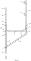
- Figure 2 shows the support structure of the framework. It comprises the bracket element (100) according to Figure 1 or according to an alternative structure disclosed in connection with Figure 1 , and an elongated, straight and longitudinally adjustable vertical support element (110) with a lower end and an upper end, which vertical support element is adapted to be mounted in a vertical position with respect to its longitudinal axis. At the lower end of the vertical support element (110) is an adjustable leg (not shown) movably attached to the longitudinal extension of the vertical support element.
- the vertical part (10) of the bracket element (100) forms a sleeve-like tube around the vertical support element (110) and is thus movably connected to the vertical support element such that the bracket element can be moved in the direction of the axis vertical to the bracket element.
- the elevation of the bracket element can thus be adjusted by moving the bracket element in the direction of the longitudinal axis of the vertical support element.
- the bracket element can be removably attached, that is, removably locked, to various elevations.
- the fastening can be implemented in a simple manner, for example by means of holes (115) made at desired intervals in the vertical support element and holes (15) made in the vertical part of the bracket element by placing a locking device in the aligned holes (15, 115) when the bracket element is at the desired height.
- the fastening can be implemented by fitting one or more spring-loaded pins in the vertical support element, which is/are automatically pushed into the corresponding hole/holes (15) in the vertical part when it aligns with the pin.
- the bracket element of Figure 2 includes a handrail post attaching part (40) to which the handrail post (140) can be attached.
- the handrail post attaching part (40) is preferably tubular, wherein it encircles the handrail post (140) in a sleeve-like manner, which can be removably placed in the handrail post attaching part (40). Attaching the handrail post to the handrail post attaching part (40) can be carried out by applying the methods described above for interconnecting the vertical support element (110) and the vertical part (10). When the handrail post is separate from the actual bracket element, the height of the handrail post can be adjusted and the bracket element is in addition smaller, which means that their storage and transport are easier.
- the handrail post (140) can be an integral part of the bracket element (100), in which case the horizontal part (20) of the bracket element and the support member (30) are attached directly to the handrail post (140).
- the handrail post (140) preferably includes at least two snap-in fasteners (41, 42), by means of which a handrail and an intermediate rail can be removably attached to the handrail post.
- the first snap-in fastener (41) is preferably located at or in vicinity of the upper end of the handrail post, and for fastening the intermediate rail, the second snap-in fastener is located between the upper and lower ends of the handrail post.
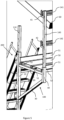
- Figure 3 shows a perspective view of a framework which comprises several of the support structures shown in Figures 1 and 2 , each of which comprises a vertical support element (110, 110') and a bracket element (100).
- the support structures are placed in a row on the face of the wall of a building in such a way that several vertical support elements (110) are in the immediate vicinity of the wall (70) of the building and there is a distance (d1, d2, d3) between the adjacent vertical support elements (10, 110') in the horizontal direction.
- the distances (d1, d2, d3) may be the same or they may vary.
- the vertical support elements (110, 110') are placed in a vertical position and at least some of the vertical support elements (110, 110') are tensioned firmly in place between the ground and the eave or roof structure of the building by means of the adjustable legs (115) located at the lower end of the vertical elements.
- the adjustable legs (115) can be adjusted, for example, by turning, in which case the adjustable leg is connected to the vertical support element by means of a screw joint.
- the adjustable leg (115) preferably has a base which rests against the supporting surface underneath it, the base extending the supporting surface of the vertical part, thus preventing it from sinking in the supporting surface, for example the ground.
- Some of the vertical support elements (110') may be left untensioned, for example, when the framework is intended to extend beyond the wall of the building.
- the adjustable leg of the vertical support element is adapted to support the lower end of the vertical support element on the supporting surface under the framework construction without fastening the adjustable leg to the supporting surface with fastening means.
- the upper end (111) of the vertical support element (110) is adapted to be supported on the lower surface of an eave or roof structure (60) extending outside the vertical line of the wall (70) of a building, and the vertical support element is adapted to be tensioned between the supporting surface and the eave or the roof structure by adjusting the height of the adjustable leg (115), wherein the adjustable leg (115) at the lower end of the vertical support element and the upper end form the sole points of support of the framework construction after tensioning.
- the vertical support element (110) and the adjacent wall is preferably left a small space which enables placing the vertical part of the bracket element around the vertical support element and moving the vertical part along the vertical support element without the adjacent wall preventing this movement.
- the adjacent vertical support elements (110) and the bracket elements (100) attached to them are preferably bound together by using a handrail (141), an intermediate rail (142) and a working platform (50).
- the snap-in fasteners (41, 42) in the supporting pillars (140) are preferably of the clamp type, in which case the handrail (141) and intermediate rail (142) running between the adjacent supporting pillars can be attached firmly to each supporting pillar, wherein the handrail and the intermediate rail bind the adjacent bracket elements together.
- the clamp-type snap-in fastener enables the use of different sizes of handrails and intermediate rails.
- a guide rail can be used metal profile, for example aluminium profile, or even a free vertical support or plank.
- Sideways support of the framework can be further improved by means of a working platform (50), which can be removably attached to each bracket element (100).
- the working platform (50) is preferably placed to rest on the horizontal parts (20) of the bracket element (100) and it may also be supported in the sideways direction on the vertical part (10) and the handrail post attaching part (40) or the handrail post (140) if the handrail post is an integral part of the bracket element.
- the cross-section of the working platform (50) is preferably basin-shaped, in which case the working platform (50) comprises an essentially even, horizontal walkway and on the edges of the walkway skirting boards rising above the upper surface. The surface of the walkway may be patterned or roughened to prevent it from being slippery.
- the working platform (50) preferably comprises support profiles below the walkway to reinforce the working platform.
- To the framework may be connected various supplementary parts, such as ladders (200) to facilitate climbing on the framework.
- ladders 200
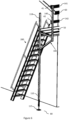
- Figure 4 shows a sideview of the framework of Figure 3 . From this viewing angle can be seen the principle according to which the vertical support elements (110) of the framework can be fixed in place by clamping.
- the upper end (111) of the vertical support element is placed against the eave or roof structure of the building and the adjustable leg (115), which is an extension of the lower end of the vertical support, is placed against the ground, floor or other supporting surface (80) in the immediate vicinity of the wall surface (70) of the building.
- the height of the adjustable leg the length of the vertical support element can be adjusted such that the vertical support element (110) can be tensioned firmly between these two points of support and no other fastening means are thereby needed.
- the hand rail (141) is preferably attached to the handrail post (140) by means of a snap-in fastener (41), which is located at or in vicinity of the upper end of the handrail post (140) and the intermediate rail (142) is attached to the handrail post (140) by means of a snap-in fastener (42), which is in elevation located between the upper end of the handrail post and the horizontal part (20) of the bracket element (100), and thus also between the upper end of the handrail post and the working platform (50).
- a snap-in fastener 41
- the intermediate rail (142) is attached to the handrail post (140) by means of a snap-in fastener (42)
- the support profiles (52) of the working platform (50) rest on top of the bracket element (20) and the edges of the working platform extending upwards form skirting boards (51) on the edges of the working platform, which prevent, for example, the feet of a person on the working platform from slipping off the working platform.
- the skirting boards (51) are preferably an integral part of the working platform (50).
- Figure 5 shows a perspective view of a detail of the framework of Figures 3 and 4 .
- the skirting boards (51) on the outer edges of the working platform (50) and the support profiles (52), which are integral parts of the working platform element and rest on the horizontal part (20) of the bracket element (50) are clearly distinguishable.
- aluminium profile has been used as the handrail (141) and the intermediate rail (142), but any sufficiently sturdy and long object is suitable for these purposes.
- the snap-in fasteners (41, 42) are shown in the Figure as simple hooks, but the snap-in fasteners are preferably adjustable, for example of the clamp type, in which case the handrail and intermediate rail can be attached firmly to the handrail post (140), wherein the desired reinforcement of the framework construction is further achieved, especially against sideways movement.
- the working platform (50) is also preferably firmly attached to the bracket element (100). An example of the attachment of the working platform to the bracket element is described in connection with Figure 9 .
- Figure 6 shows, by way of an example, the end of the framework construction shown in the preceding Figures, and especially the height-adjustable adjustable leg (115) at the lower end of the vertical support element (110).
- the end of the adjustable leg against the supporting surface may comprise a base, which allows for a larger contact surface than the vertical support element (110) itself and reduces the pressure exerted per unit area of the supporting surface, and which may also increase friction between the adjustable leg (115) and the supporting surface (80).
- the structure described by means of the preceding Figures enables the mounting and dismounting of the framework construction such that the framework can be mounted as a whole from the ground without having to lift the parts of the framework during mounting for the purpose of mounting, for example, with a crane or person hoist, and also without the need to climb on an insufficiently equipped framework during erection or dismounting. Occupational safety is thus improved with respect to known framework solutions.
- Figure 7 shows an alternative not included in the scope of claims, wherein the vertical support elements (110) are attached by using appropriate fastening means only to the eave and/or wall structure, in which case an adjustable leg is not needed at the lower end of the vertical support elements (110). Most of the length of the vertical support element (110) attached to the wall and/or eave is not attached to the wall surface, which means that the bracket element (100) can be moved along the vertical support element (110), thus adjusting the elevation of the bracket element (100) and the working platform carried by it in the direction of the longitudinal axis of the vertical support element (110).
- the vertical support element (110) For the purpose of adjusting the elevation, between the vertical support element (110) and the adjacent wall is preferably a small but sufficient space which allows the vertical part of the bracket element to be positioned and moved with respect to the longitudinal axis of the vertical support element.
- the vertical support elements may be considered to "hang" from their upper end. In this connection, hanging means that the vertical support element is not supported by its lower end on the ground or on other similar horizontal supporting surface. If so desired, the vertical support element (110) can, however, be attached to the wall structure also from its lower end, in which case the bracket element can be moved between the points of attachment.
- This alternative embodiment can be used, for example, in the case that attaching one or more vertical support elements (110) by clamping between the ground and the eave is not possible. This situation may arise, for example, due to the excessive height of the eave.
- the fastening of the vertical support elements (110) in a manner suitable for this purpose from their upper parts to the wall and/or to the eave is carried out, for example, by using a person lift. Since the vertical support elements only constitute a part of the overall mass of the scaffolding, the attachment can be carried out quickly and easily.
- the elevation of the working area entity supported by the bracket elements (100) is adjustable along the longitudinal axis of the vertical support elements (110).
- the bracket elements (100) can be attached to the vertical support elements (110) once these have been attached. Any separate handrail posts (140) required can be attached to the bracket elements (100), and the working platforms (50), handrails (141) and intermediate rails (142) can be attached to the bracket elements (100) and/or handrail posts (140) when the bracket elements (100) are at the lower end of the vertical support element (110), and the working area entity can be lifted to working height as an entity.
- the vertical support elements (110) can also be attached from their lower part to the wall, however, in such a way that most of the length of each vertical support element (110) does not comprise fastening means for fastening to the wall, wherein height adjustment of the bracket elements (100) and the working area entity (100, 50, 40 or 140, 141, 142) carried by them is possible.
- Figures 8a to 8d show the mounting steps of the framework.
- the vertical support elements (110) are tensioned in a row at the desired horizontal intervals between the supporting surface (80) and the roof structure (60).
- additional vertical support elements (110') the adjustable legs of which rest against the supporting surface, but which are not tensioned on the roof structure, for example in the case that there is no suitable roof structure or eave above the additional vertical support element (110') in question.
- This type of additional vertical support element (110') may be located, for example, at either end of a row of vertical support elements (110).
- the bracket structure (100) is preferably down below in the vicinity of the supporting surface (80) for the mounting of the working area entity to take place next.
- the lower end of the vertical part of the bracket structure (100) may, for example, rest on the adjustable leg (115) of the vertical support element, or the bracket structure can be removably attached to a lower position in the vicinity of the lower end of the vertical support element (110) and at the same time of the adjustable leg (115). If the handrail post (140) is an element separate from the bracket structure (100), the handrail post can in this step be placed in position and attached removably to the attaching part (40) of the handrail post.
- the locking mechanism used for this purpose may be, for example, any of the mentioned locking mechanisms, by means of which the vertical part (10) is removably attached in place in the vertical support element (110), such as a separate locking pin passed through the holes in the handrail post attaching part (40) and the handrail post, or a spring-loaded locking pin located in the handrail post, which automatically extends into the hole in the handrail post attaching part (40) when it aligns with the spring-loaded locking pin.
- the vertical support elements (110) are attached with fastening means in a row in the wall and/or eave structure at desired horizontal intervals.
- This alternative is not included in the scope of claims.
- the bracket structure (100) is down below in the vicinity of the supporting surface (80).
- the bracket structure can be removably attached to a lower position in the vicinity of the lower end of the vertical support element (110) for mounting the working area entity.
- the handrail post (140) is an element separate from the bracket structure (100), the handrail post can in this step be removably attached in place as described above.
- a working platform (50) which is supported on the bracket elements (100) of at least two adjacent support structures, and rests on their horizontal parts (20).
- the handrail (141) and the intermediate rail (142) are attached to the snap-in fasteners (41, 42) of the handrail posts (140) of adjacent support structures, which are adjusted to attach the handrail and intermediate rail firmly but removably in place.
- the working area entity constituted by the bracket elements, the working platform, the handrail and the intermediate rail is now assembled, including the structural elements required by occupational safety regulations.
- the working platform (50) can be placed in position before mounting the handrail posts (140), which is described above in step 8a).
- the working area entity constituted by the bracket elements, the working platform, the handrail and the intermediate rail has been lifted to the desired working height.
- the lifting can take place, for example, by means of a winch system connected to one or more motors suitable for the purpose, which can be used without climbing on the framework.
- the bracket element is removably attached to the vertical support element by using one of the previously mentioned fastening means.
- the motor used can be, for example, an electric motor.
- the framework has been further supplemented by mounting additional parts, for example a ladder (200).
- additional parts for example a ladder (200). This step is optional, as are the additional parts used.
- Figure 9 shows diagrammatically an example of the fastening of the working platform to the bracket element.
- fastening pins (95) for fastening the working platform (50) at least one fastening pin close to both ends of the horizontal part (20).
- the fastening pins preferably extend directly upwards from the horizontal part, for example from its upper surface.
- On the opposite longitudinal edges of the working platform (50) may correspondingly be holes (90) adapted to the size of the fastening pin for fastening at desired intervals. If the working platform (50) comprises support profiles (52), the holes (90) may also pass through the support profiles.
- the fastening pins are placed such that they will pass through the desired holes (90) on both edges of the working platform (50).
- the fastening of the working platform can be secured, for example, by means of a locking pin (not shown) to be attached to each fastening pin (95) from above the working platform (50), or in another manner suitable for the purpose.
- a locking pin is used, the working platform (50) preferably settles between the horizontal part (20) and the locking pin.
- the working platform (50) is fastened in this manner to at least two adjacent bracket elements (100), the framework construction becomes reinforced in the sideways direction.
- Figure 9 also shows an alternative where the handrail post (140) is an integral part of the bracket element (100).
- Figure 9 The method for fastening the working platform shown in Figure 9 can be applied irrespective of whether the handrail post is a part of the bracket element (100) or a separate handrail post (140) is used, which is attached to the attaching part (40) of the handrail post.
- Figure 9 does not show the skirting boards, but the disclosed fastening mechanism can also be used when the working platform comprises the previously described skirting boards on its opposite longitudinal edges.
- a framework support structure which comprises an elongated, straight vertical support element with a lower end and an upper end, the vertical support element being adapted to be mounted in a vertical position with respect to its longitudinal axis, and a bracket element movably connectable to the vertical support element.
- the bracket element comprises a vertical part which, when connected to the vertical support element, encircles the vertical support element in a sleeve-like manner, and which is movably connectable to the vertical support element in such a way that the elevation of the vertical part, and at the same time of the entire bracket element, is adjustable in the direction of the longitudinal axis of the vertical support element, and a horizontal part, which attaches to the vertical part by its first end, and the longitudinal axis of which extends from the vertical part on the horizontal plane.
- the bracket element further comprises a handrail post or a handrail post attaching part which attaches to the second end of the horizontal part, and the longitudinal axis of which is parallel with the vertical part, and a support member which attaches by its first end to the vertical part below the horizontal part, and which rises from this attachment point diagonally upwards in the longitudinal direction of the support member such that the second end of the support member attached to the horizontal part is higher than the first end of the support member and attaches to the handrail post or the handrail post support member.
- an adjustable leg movably attached to the longitudinal extension of the vertical support element, whereby the length of the vertical support element can be adjusted, which means that the adjustable leg of the vertical support element is adapted to support the lower end of the vertical support element on the supporting surface under the framework construction without attaching the adjustable leg to the supporting surface with fastening means, and wherein the upper end of the vertical support element is adapted to be supported on the lower surface of an eave or roof structure, wherein the vertical support element is adapted to be tensioned between the supporting surface and the eave or roof structure by adjusting the height of the adjustable leg, wherein the adjustable leg at the lower end of the vertical support element and the upper end form the sole points of support of the framework construction after tensioning, or the vertical support element is adapted to be attached with fastening means at least from its upper part to a wall and/or roof structure such that the lower end of the vertical support element does not reach the supporting surface under the framework construction.
- the elevation of the bracket element can be adjusted by moving the bracket element in
- a framework construction which comprises at least two of the above-mentioned framework support structures which are placed against the wall of a building and thus form a row of support structures of at least two adjacent frameworks.
- the bracket elements connected to the at least two framework support structures are placed at the same horizontal height, wherein a row of at least two adjacent bracket elements is also formed, wherein between the adjacent framework support structures and the adjacent bracket elements is a distance in the horizontal direction.
- the bracket element comprises a handrail post attaching part
- the framework construction also comprises a handrail post removably attachable to the handrail post attaching part.
- the framework construction further comprises a working platform which is removably attached onto the adjacent horizontal parts of the bracket element, and which working platform comprises an essentially even upper surface and, below the upper surface of the working platform, support profiles extending horizontally between adjacent support structures, a handrail which is removably attached to or in vicinity of the upper end of the adjacent handrail posts of the bracket element, the handrail running between the handrail posts of the adjacent bracket elements, thus forming a first horizontal rail, and an intermediate rail, which is removably attached between the upper and lower ends of the handrail posts of adjacent bracket elements, wherein the intermediate rail runs between the handrail posts of the adjacent bracket elements, thus forming a second horizontal rail.
- the elevation of the working area entity consisting of the support structure of the framework construction, the working platform, the handrail and the intermediate rail is adapted to be mounted at the desired working height by adjusting the elevation of the at least two bracket elements by moving the at least two bracket elements along the longitudinal axis of the vertical support elements and by fixing the working area entity to the desired working height by removably attaching each bracket element to the corresponding vertical support element.
- the working platform has a basin-like structure in cross-section, wherein the outer edges of the working platform, which extend upwards from the working platform, form skirting boards on the sides of the vertical support structure of the working platform and the handrail post.
- a framework construction is provided as mentioned above, wherein above the horizontal part of the bracket element, in the vicinity of the opposite ends of the horizontal part, at least two fastening pins extend from the horizontal part.
- the working platform In the opposite longitudinal edge areas of the working platform are holes for attachment, whereby the working platform is adapted to be fixed on top of the bracket element by placing the fastening pins in the corresponding holes in the working platform and by securing the attachment of the working platform with a removably attachable locking mechanism.
- each handrail post comprises at least two adaptable clamp elements for removably attaching the first handrail and the first intermediate rail to the handrail post.
- a framework construction as mentioned above wherein the vertical support element, bracket element and handrail post and/or handrail post attaching part are made of aluminium.
- a method for mounting a framework construction comprising at least two elongated, straight vertical support elements with a lower end and an upper end, and a bracket element movably connectable to each vertical support element.
- Each bracket element comprises a vertical part which, when connected to the vertical support element, encircles the vertical support element in a sleeve-like manner, and which is thereby movably connected to the vertical support element in such a way that the position of the vertical part, and at the same time of the entire bracket element, is adjustable in the direction of the longitudinal axis of the vertical support element, and a horizontal part, which is attached to the vertical part by its first end, and the longitudinal axis of which extends from the vertical part on the horizontal plane.
- Each bracket element further comprises a handrail post or a handrail post attaching part which attaches to the second end of the horizontal part, and the longitudinal axis of which is parallel with the vertical part, and a support member which attaches by its first end to the vertical part below the horizontal part, and which rises from this attachment point diagonally upwards in the longitudinal direction of the support member such that the second end of the support member attached to the horizontal part is higher than the first end and attaches to the handrail post or the handrail post support member.
- the method comprises a step in which the at least two vertical support elements are placed parallel with respect to their longitudinal axes, in a vertical position, such that the at least two vertical support elements are positioned in a row against the wall of the building, wherein there is a distance between the adjacent vertical support elements in the horizontal direction, and wherein each bracket element is positioned at the lower end of the corresponding vertical support element or in its vicinity.
- each vertical support element is adjusted by means of the adjustable leg movably attached to its lower end, to the longitudinal extension of the vertical support element, such that the lower end of each vertical support element is supported by means of the adjustable leg on the supporting surface below the framework construction without fastening the adjustable leg with fastening means to the supporting surface, and that the upper end of the vertical support element is supported against the lower surface of an eave or roof structure, wherein the vertical support element is fixed in place by being clamped between the supporting surface below and the eave or roof structure above, and wherein the adjustable leg at the lower end of each vertical support element and the upper end form the sole points of support of the framework construction, or each vertical support element is fastened with fastening means at least at its upper end to the eave and/or the wall structure such that the lower end of the vertical support element does not reach the supporting surface under the framework construction.
- a working platform is removably attached on top of at least two adjacent bracket elements, in which case the working platform comprises a horizontal upper surface and, below the upper surface of the working platform, at least two support profiles extending horizontally between at least two adjacent support structures.
- the bracket element comprises a handrail post attaching part
- the handrail post is removably attached to the handrail post attaching part.
- the handrail is removably attached to or in the vicinity of the upper end of the handrail post of at least two adjacent bracket elements, wherein the handrail runs between the handrail posts of at least two adjacent bracket elements, thus forming a first horizontal railing
- an intermediate rail is removably attached between the upper and lower ends of the handrail post of at least two adjacent bracket elements, wherein the intermediate rail runs between the handrail posts of at least two adjacent bracket elements, thus forming a second horizontal railing.
- the working area entity comprising the bracket elements, the working platform, the handrail and the intermediate rail is lifted to the desired working height by adjusting the elevation of the bracket elements by moving each bracket element in the direction of the longitudinal axis of the corresponding vertical support element, and the working area entity is removably fixed to the desired working height by removably attaching each bracket element to the corresponding vertical support element.
- the method further comprises removably attaching the working platform onto the horizontal part of the bracket element by means of fastening pins extending from the horizontal part in the vicinity of the opposite ends of the horizontal part above each horizontal part, wherein the fastening pins are placed in the corresponding holes in the edge areas of the working platform, and the attachment of the working platform is secured by means of a removably attachable locking mechanism.
- the method further comprises removably attaching the first handrail and the first intermediate rail to a handrail post by means of two adaptable clamp elements attached to the handrail post.
- lifting the working area entity to the desired working height is carried out by means of at least one motor-driven winch system.
Landscapes
- Engineering & Computer Science (AREA)
- Architecture (AREA)
- Mechanical Engineering (AREA)
- Civil Engineering (AREA)
- Structural Engineering (AREA)
- Steps, Ramps, And Handrails (AREA)
- Conveying And Assembling Of Building Elements In Situ (AREA)
Applications Claiming Priority (2)
| Application Number | Priority Date | Filing Date | Title |
|---|---|---|---|
| FI20205803 | 2020-08-18 | ||
| EP21191308.2A EP3957807B1 (fr) | 2020-08-18 | 2021-08-13 | Une structure de support d'échafaudage et une méthode d'assemblage d'échafaudages |
Related Parent Applications (1)
| Application Number | Title | Priority Date | Filing Date |
|---|---|---|---|
| EP21191308.2A Division EP3957807B1 (fr) | 2020-08-18 | 2021-08-13 | Une structure de support d'échafaudage et une méthode d'assemblage d'échafaudages |
Publications (2)
| Publication Number | Publication Date |
|---|---|
| EP4293175A2 true EP4293175A2 (fr) | 2023-12-20 |
| EP4293175A3 EP4293175A3 (fr) | 2024-02-28 |
Family
ID=77518922
Family Applications (2)
| Application Number | Title | Priority Date | Filing Date |
|---|---|---|---|
| EP23206919.5A Pending EP4293175A3 (fr) | 2020-08-18 | 2021-08-13 | Structure de support d'échafaudage et procédé d'assemblage d'échafaudage |
| EP21191308.2A Active EP3957807B1 (fr) | 2020-08-18 | 2021-08-13 | Une structure de support d'échafaudage et une méthode d'assemblage d'échafaudages |
Family Applications After (1)
| Application Number | Title | Priority Date | Filing Date |
|---|---|---|---|
| EP21191308.2A Active EP3957807B1 (fr) | 2020-08-18 | 2021-08-13 | Une structure de support d'échafaudage et une méthode d'assemblage d'échafaudages |
Country Status (1)
| Country | Link |
|---|---|
| EP (2) | EP4293175A3 (fr) |
Citations (5)
| Publication number | Priority date | Publication date | Assignee | Title |
|---|---|---|---|---|
| ES1001092Y (es) | 1986-11-25 | 1988-12-16 | Mundus Cataluna, S.A. | Andamio perfeccionado |
| CN1279374A (zh) | 1999-06-25 | 2001-01-10 | 小野辰雄 | 构架及由构架装配而成的结构 |
| AU2003101011A4 (en) | 2003-05-15 | 2004-02-05 | John Royden Ellis | Scaffolding apparatus |
| WO2007012017A2 (fr) | 2005-07-19 | 2007-01-25 | Teleflex Medical Incorporated | Mandrin a cliquet et son procede de fabrication |
| GB2489818A (en) | 2011-04-04 | 2012-10-10 | Easi Dec Access Systems Ltd | Access platform with extendable wing barriers |
Family Cites Families (5)
| Publication number | Priority date | Publication date | Assignee | Title |
|---|---|---|---|---|
| BE538792A (fr) * | 1954-06-09 | 1955-06-30 | Verdier, R. | Echafaudage a montants extensibles et reglables pour montage et demontage rapide a l'interieur de batiments |
| AU7040391A (en) * | 1989-10-27 | 1991-05-31 | Ab Pa-So Produkter | Hanging scaffold |
| DE19846470A1 (de) * | 1998-10-09 | 2000-04-13 | Baumann Verwertungs Gmbh | Baugerüst |
| US20060163001A1 (en) * | 2005-01-24 | 2006-07-27 | Pozell Charles A | Wall hanging scaffold |
| FI126773B (fi) * | 2012-08-14 | 2017-05-15 | Hämeen Laaturemontti Oy | Kattotyöskentelyn kaiderakenteen pystytukirakenne |
-
2021
- 2021-08-13 EP EP23206919.5A patent/EP4293175A3/fr active Pending
- 2021-08-13 EP EP21191308.2A patent/EP3957807B1/fr active Active
Patent Citations (5)
| Publication number | Priority date | Publication date | Assignee | Title |
|---|---|---|---|---|
| ES1001092Y (es) | 1986-11-25 | 1988-12-16 | Mundus Cataluna, S.A. | Andamio perfeccionado |
| CN1279374A (zh) | 1999-06-25 | 2001-01-10 | 小野辰雄 | 构架及由构架装配而成的结构 |
| AU2003101011A4 (en) | 2003-05-15 | 2004-02-05 | John Royden Ellis | Scaffolding apparatus |
| WO2007012017A2 (fr) | 2005-07-19 | 2007-01-25 | Teleflex Medical Incorporated | Mandrin a cliquet et son procede de fabrication |
| GB2489818A (en) | 2011-04-04 | 2012-10-10 | Easi Dec Access Systems Ltd | Access platform with extendable wing barriers |
Also Published As
| Publication number | Publication date |
|---|---|
| EP4293175A3 (fr) | 2024-02-28 |
| EP3957807C0 (fr) | 2023-11-01 |
| EP3957807B1 (fr) | 2023-11-01 |
| EP3957807A1 (fr) | 2022-02-23 |
Similar Documents
| Publication | Publication Date | Title |
|---|---|---|
| US5842685A (en) | Temporary guard rail system | |
| US6003630A (en) | Unilateral scaffold system | |
| US6840350B2 (en) | Adjustable scaffold and walkboard ladder holder | |
| US8245816B2 (en) | Integral safety system which can be used for construction | |
| US20050072628A1 (en) | Hanging scaffold support | |
| US20100293875A1 (en) | Stairway for Use on Building Sites | |
| US8186479B2 (en) | Roof scaffolding system | |
| EP1700973B1 (fr) | Console de support pour échelles | |
| US6883642B2 (en) | Method of ladder-supported scaffold erection, and ladder bracing and scaffolding system for use therewith | |
| US7051838B1 (en) | Scaffolding system, integral safety rail therefor and methods of making the same | |
| EP0606948B1 (fr) | Construction de support universel | |
| US6799658B2 (en) | Mobile outrigger scaffolding system | |
| EP3957807B1 (fr) | Une structure de support d'échafaudage et une méthode d'assemblage d'échafaudages | |
| US20110088237A1 (en) | Novel scaffolding apparatus and method | |
| US5242029A (en) | Poolside descending scaffold | |
| GB2157755A (en) | Roof scaffolding | |
| CA2980829A1 (fr) | Systeme d'echafaudage pour toiture | |
| EP1876315A1 (fr) | Systeme de securite integre applicable a des constructions | |
| US20030047385A1 (en) | Mobile outrigger scaffolding system | |
| CN117403862A (zh) | 用于斜屋面施工的可滑动模块化操作平台及其施工方法 | |
| AU669575B2 (en) | Support assembly | |
| JPH0755777B2 (ja) | エレベータの据付工法および据付用作業床装置 | |
| CA2245136C (fr) | Dispositif de fixation pour garde-fou destine a une structure en beton | |
| EP1650378A1 (fr) | Structure d'echafaudage suspendue destinee a des travaux de facade | |
| AU2119099A (en) | Stabilising and handrail assemblies for trestles |
Legal Events
| Date | Code | Title | Description |
|---|---|---|---|
| PUAI | Public reference made under article 153(3) epc to a published international application that has entered the european phase |
Free format text: ORIGINAL CODE: 0009012 |
|
| STAA | Information on the status of an ep patent application or granted ep patent |
Free format text: STATUS: THE APPLICATION HAS BEEN PUBLISHED |
|
| AC | Divisional application: reference to earlier application |
Ref document number: 3957807 Country of ref document: EP Kind code of ref document: P |
|
| AK | Designated contracting states |
Kind code of ref document: A2 Designated state(s): AL AT BE BG CH CY CZ DE DK EE ES FI FR GB GR HR HU IE IS IT LI LT LU LV MC MK MT NL NO PL PT RO RS SE SI SK SM TR |
|
| REG | Reference to a national code |
Ref country code: DE Ref legal event code: R079 Free format text: PREVIOUS MAIN CLASS: E04G0005040000 Ipc: E04G0001150000 |
|
| PUAL | Search report despatched |
Free format text: ORIGINAL CODE: 0009013 |
|
| AK | Designated contracting states |
Kind code of ref document: A3 Designated state(s): AL AT BE BG CH CY CZ DE DK EE ES FI FR GB GR HR HU IE IS IT LI LT LU LV MC MK MT NL NO PL PT RO RS SE SI SK SM TR |
|
| RIC1 | Information provided on ipc code assigned before grant |
Ipc: E04G 5/04 20060101ALI20240124BHEP Ipc: E04G 7/30 20060101ALI20240124BHEP Ipc: E04G 5/10 20060101ALI20240124BHEP Ipc: E04G 5/08 20060101ALI20240124BHEP Ipc: E04G 5/06 20060101ALI20240124BHEP Ipc: E04G 5/02 20060101ALI20240124BHEP Ipc: E04G 3/22 20060101ALI20240124BHEP Ipc: E04G 3/20 20060101ALI20240124BHEP Ipc: E04G 1/38 20060101ALI20240124BHEP Ipc: E04G 1/15 20060101AFI20240124BHEP |