EP4292960A1 - Device for providing separated stamped parts - Google Patents
Device for providing separated stamped parts Download PDFInfo
- Publication number
- EP4292960A1 EP4292960A1 EP23179801.8A EP23179801A EP4292960A1 EP 4292960 A1 EP4292960 A1 EP 4292960A1 EP 23179801 A EP23179801 A EP 23179801A EP 4292960 A1 EP4292960 A1 EP 4292960A1
- Authority
- EP
- European Patent Office
- Prior art keywords
- carrier
- stamped parts
- parts
- stamped
- separating
- Prior art date
- Legal status (The legal status is an assumption and is not a legal conclusion. Google has not performed a legal analysis and makes no representation as to the accuracy of the status listed.)
- Pending
Links
- 238000004519 manufacturing process Methods 0.000 claims abstract description 11
- 239000010970 precious metal Substances 0.000 claims abstract description 9
- 125000006850 spacer group Chemical group 0.000 claims description 12
- 238000000034 method Methods 0.000 claims description 6
- 230000003287 optical effect Effects 0.000 claims description 4
- 230000000737 periodic effect Effects 0.000 claims description 4
- 238000005303 weighing Methods 0.000 claims description 3
- 230000007704 transition Effects 0.000 claims description 2
- 238000000926 separation method Methods 0.000 description 8
- 238000011161 development Methods 0.000 description 7
- 239000000463 material Substances 0.000 description 7
- 230000005484 gravity Effects 0.000 description 6
- 230000008901 benefit Effects 0.000 description 3
- 239000013590 bulk material Substances 0.000 description 3
- 230000006835 compression Effects 0.000 description 3
- 238000007906 compression Methods 0.000 description 3
- 230000007423 decrease Effects 0.000 description 3
- PCHJSUWPFVWCPO-UHFFFAOYSA-N gold Chemical compound [Au] PCHJSUWPFVWCPO-UHFFFAOYSA-N 0.000 description 3
- 239000010931 gold Substances 0.000 description 3
- 229910052737 gold Inorganic materials 0.000 description 3
- 238000005259 measurement Methods 0.000 description 3
- 238000004080 punching Methods 0.000 description 3
- 239000002699 waste material Substances 0.000 description 3
- 230000000694 effects Effects 0.000 description 2
- 238000005286 illumination Methods 0.000 description 2
- 230000036962 time dependent Effects 0.000 description 2
- 230000008859 change Effects 0.000 description 1
- 238000004140 cleaning Methods 0.000 description 1
- 238000009826 distribution Methods 0.000 description 1
- 238000004049 embossing Methods 0.000 description 1
- 238000002955 isolation Methods 0.000 description 1
- 230000004048 modification Effects 0.000 description 1
- 238000012986 modification Methods 0.000 description 1
- 230000008092 positive effect Effects 0.000 description 1
- 230000008569 process Effects 0.000 description 1
- 238000012545 processing Methods 0.000 description 1
- 238000000275 quality assurance Methods 0.000 description 1
- 238000003860 storage Methods 0.000 description 1
Images

Classifications
-
- B—PERFORMING OPERATIONS; TRANSPORTING
- B65—CONVEYING; PACKING; STORING; HANDLING THIN OR FILAMENTARY MATERIAL
- B65G—TRANSPORT OR STORAGE DEVICES, e.g. CONVEYORS FOR LOADING OR TIPPING, SHOP CONVEYOR SYSTEMS OR PNEUMATIC TUBE CONVEYORS
- B65G47/00—Article or material-handling devices associated with conveyors; Methods employing such devices
- B65G47/22—Devices influencing the relative position or the attitude of articles during transit by conveyors
- B65G47/26—Devices influencing the relative position or the attitude of articles during transit by conveyors arranging the articles, e.g. varying spacing between individual articles
- B65G47/28—Devices influencing the relative position or the attitude of articles during transit by conveyors arranging the articles, e.g. varying spacing between individual articles during transit by a single conveyor
-
- B—PERFORMING OPERATIONS; TRANSPORTING
- B65—CONVEYING; PACKING; STORING; HANDLING THIN OR FILAMENTARY MATERIAL
- B65G—TRANSPORT OR STORAGE DEVICES, e.g. CONVEYORS FOR LOADING OR TIPPING, SHOP CONVEYOR SYSTEMS OR PNEUMATIC TUBE CONVEYORS
- B65G47/00—Article or material-handling devices associated with conveyors; Methods employing such devices
- B65G47/02—Devices for feeding articles or materials to conveyors
- B65G47/04—Devices for feeding articles or materials to conveyors for feeding articles
- B65G47/12—Devices for feeding articles or materials to conveyors for feeding articles from disorderly-arranged article piles or from loose assemblages of articles
- B65G47/14—Devices for feeding articles or materials to conveyors for feeding articles from disorderly-arranged article piles or from loose assemblages of articles arranging or orientating the articles by mechanical or pneumatic means during feeding
- B65G47/1492—Devices for feeding articles or materials to conveyors for feeding articles from disorderly-arranged article piles or from loose assemblages of articles arranging or orientating the articles by mechanical or pneumatic means during feeding the articles being fed from a feeding conveyor
-
- B—PERFORMING OPERATIONS; TRANSPORTING
- B26—HAND CUTTING TOOLS; CUTTING; SEVERING
- B26D—CUTTING; DETAILS COMMON TO MACHINES FOR PERFORATING, PUNCHING, CUTTING-OUT, STAMPING-OUT OR SEVERING
- B26D7/00—Details of apparatus for cutting, cutting-out, stamping-out, punching, perforating, or severing by means other than cutting
- B26D7/27—Means for performing other operations combined with cutting
- B26D7/30—Means for performing other operations combined with cutting for weighing cut product
-
- B—PERFORMING OPERATIONS; TRANSPORTING
- B26—HAND CUTTING TOOLS; CUTTING; SEVERING
- B26D—CUTTING; DETAILS COMMON TO MACHINES FOR PERFORATING, PUNCHING, CUTTING-OUT, STAMPING-OUT OR SEVERING
- B26D7/00—Details of apparatus for cutting, cutting-out, stamping-out, punching, perforating, or severing by means other than cutting
- B26D7/27—Means for performing other operations combined with cutting
- B26D7/32—Means for performing other operations combined with cutting for conveying or stacking cut product
-
- B—PERFORMING OPERATIONS; TRANSPORTING
- B44—DECORATIVE ARTS
- B44B—MACHINES, APPARATUS OR TOOLS FOR ARTISTIC WORK, e.g. FOR SCULPTURING, GUILLOCHING, CARVING, BRANDING, INLAYING
- B44B5/00—Machines or apparatus for embossing decorations or marks, e.g. embossing coins
- B44B5/02—Dies; Accessories
- B44B5/024—Work piece loading or discharging arrangements
-
- B—PERFORMING OPERATIONS; TRANSPORTING
- B65—CONVEYING; PACKING; STORING; HANDLING THIN OR FILAMENTARY MATERIAL
- B65G—TRANSPORT OR STORAGE DEVICES, e.g. CONVEYORS FOR LOADING OR TIPPING, SHOP CONVEYOR SYSTEMS OR PNEUMATIC TUBE CONVEYORS
- B65G15/00—Conveyors having endless load-conveying surfaces, i.e. belts and like continuous members, to which tractive effort is transmitted by means other than endless driving elements of similar configuration
- B65G15/30—Belts or like endless load-carriers
-
- B—PERFORMING OPERATIONS; TRANSPORTING
- B65—CONVEYING; PACKING; STORING; HANDLING THIN OR FILAMENTARY MATERIAL
- B65G—TRANSPORT OR STORAGE DEVICES, e.g. CONVEYORS FOR LOADING OR TIPPING, SHOP CONVEYOR SYSTEMS OR PNEUMATIC TUBE CONVEYORS
- B65G25/00—Conveyors comprising a cyclically-moving, e.g. reciprocating, carrier or impeller which is disengaged from the load during the return part of its movement
- B65G25/04—Conveyors comprising a cyclically-moving, e.g. reciprocating, carrier or impeller which is disengaged from the load during the return part of its movement the carrier or impeller having identical forward and return paths of movement, e.g. reciprocating conveyors
- B65G25/08—Conveyors comprising a cyclically-moving, e.g. reciprocating, carrier or impeller which is disengaged from the load during the return part of its movement the carrier or impeller having identical forward and return paths of movement, e.g. reciprocating conveyors having impellers, e.g. pushers
-
- B—PERFORMING OPERATIONS; TRANSPORTING
- B65—CONVEYING; PACKING; STORING; HANDLING THIN OR FILAMENTARY MATERIAL
- B65G—TRANSPORT OR STORAGE DEVICES, e.g. CONVEYORS FOR LOADING OR TIPPING, SHOP CONVEYOR SYSTEMS OR PNEUMATIC TUBE CONVEYORS
- B65G27/00—Jigging conveyors
- B65G27/10—Applications of devices for generating or transmitting jigging movements
- B65G27/12—Applications of devices for generating or transmitting jigging movements of shaking devices, i.e. devices for producing movements of low frequency and large amplitude
-
- B—PERFORMING OPERATIONS; TRANSPORTING
- B65—CONVEYING; PACKING; STORING; HANDLING THIN OR FILAMENTARY MATERIAL
- B65G—TRANSPORT OR STORAGE DEVICES, e.g. CONVEYORS FOR LOADING OR TIPPING, SHOP CONVEYOR SYSTEMS OR PNEUMATIC TUBE CONVEYORS
- B65G27/00—Jigging conveyors
- B65G27/10—Applications of devices for generating or transmitting jigging movements
- B65G27/16—Applications of devices for generating or transmitting jigging movements of vibrators, i.e. devices for producing movements of high frequency and small amplitude
- B65G27/18—Mechanical devices
-
- B—PERFORMING OPERATIONS; TRANSPORTING
- B65—CONVEYING; PACKING; STORING; HANDLING THIN OR FILAMENTARY MATERIAL
- B65G—TRANSPORT OR STORAGE DEVICES, e.g. CONVEYORS FOR LOADING OR TIPPING, SHOP CONVEYOR SYSTEMS OR PNEUMATIC TUBE CONVEYORS
- B65G27/00—Jigging conveyors
- B65G27/10—Applications of devices for generating or transmitting jigging movements
- B65G27/32—Applications of devices for generating or transmitting jigging movements with means for controlling direction, frequency or amplitude of vibration or shaking movement
-
- B—PERFORMING OPERATIONS; TRANSPORTING
- B65—CONVEYING; PACKING; STORING; HANDLING THIN OR FILAMENTARY MATERIAL
- B65G—TRANSPORT OR STORAGE DEVICES, e.g. CONVEYORS FOR LOADING OR TIPPING, SHOP CONVEYOR SYSTEMS OR PNEUMATIC TUBE CONVEYORS
- B65G43/00—Control devices, e.g. for safety, warning or fault-correcting
- B65G43/08—Control devices operated by article or material being fed, conveyed or discharged
-
- G—PHYSICS
- G07—CHECKING-DEVICES
- G07D—HANDLING OF COINS OR VALUABLE PAPERS, e.g. TESTING, SORTING BY DENOMINATIONS, COUNTING, DISPENSING, CHANGING OR DEPOSITING
- G07D9/00—Counting coins; Handling of coins not provided for in the other groups of this subclass
- G07D9/008—Feeding coins from bulk
-
- B—PERFORMING OPERATIONS; TRANSPORTING
- B65—CONVEYING; PACKING; STORING; HANDLING THIN OR FILAMENTARY MATERIAL
- B65G—TRANSPORT OR STORAGE DEVICES, e.g. CONVEYORS FOR LOADING OR TIPPING, SHOP CONVEYOR SYSTEMS OR PNEUMATIC TUBE CONVEYORS
- B65G2814/00—Indexing codes relating to loading or unloading articles or bulk materials
- B65G2814/03—Loading or unloading means
- B65G2814/0344—Control or feeding or discharging using level or weight measuring means
Definitions
- the invention relates to a device and a method for providing individual stamped parts, which preferably consist of precious metal, for the production of embossed products.
- stamps To produce embossed products, for example coins, from precious metal, it is known to feed stamped parts to a press in which the stamped parts are embossed. Such stamped parts are also referred to as blanks. To do this, the blanks must first be separated. If reference is made to blanks in the following, this can mean any stamped parts made of precious metal for the production of embossed products, e.g. bars or polygonal parts.
- stacks of blanks are also known, which are held in a vertically aligned holding device ( Fig. 1 ). At the lower end of the holding device there is an opening from which a blank can be removed from the stack. For this purpose, a stack of blanks is brought closer to an automatic separating device, which pushes the lowest blank out of the stack. This blank is then conveyed towards the press via a linear conveyor device.
- the height of the stack of blanks is limited due to the blank material. There should not be too much weight on the lowest blank, otherwise the blank can no longer be separated. This problem occurs particularly with gold discs. Gold blanks are difficult to separate and dose. The feed rate of individual blanks is therefore already limited. On the other hand, it takes time to remove an empty stack from the separating device and bring in a new, full stack. Isolation is therefore not possible during this time. A continuous supply of blanks is not possible because blanks are fed discontinuously due to stack changes.
- a magazine is required to form a stack, i.e. different sizes of magazines are required for different types of blanks.
- An additional, external device is required to fill a magazine with a stack.
- the invention is based on the object of providing a device and a method for separating stamped parts made of precious metal for the production of embossed products, with which the disadvantages of the prior art are at least largely avoided.
- the device according to the invention has a carrier for receiving stamped parts, in particular from a heap of stamped parts.
- a carrier for receiving stamped parts in particular from a heap of stamped parts.
- blanks or a disordered pile of blanks can be piled up easily and independently of the size and shape of the blanks. Filling can be done by hand or mechanically.
- the device according to the invention further has a means for separating the stamped parts, comprising a conveyor device with a vibrating carrier.
- the separation ensures that isolated blanks can be made available for the further process, whereby the provision of isolated blanks to the next processing station can be controlled depending on the number of blanks required in the press.
- the carrier of the means for separating the stamped parts is mounted in order to carry out an oscillating movement, in particular an oscillating movement along the conveying direction.
- the blanks Due to the oscillating and particularly low-frequency (below 30 Hz) movement of the carrier, the blanks are both conveyed in the conveying direction and separated.
- the oscillating movement of the carrier is particularly advantageous because it allows a material-friendly combination of conveying the blanks in the conveying direction and separating the blanks, which is inherently important in the field of application of the invention, to be achieved.
- Vibration conveyors are known that transport bulk material through periodic micro-throwing movements.
- Such vibration conveyors include a resiliently clamped conveying surface that is set into periodic vibration with the help of electromagnets. The vibration causes the bulk material to be lifted by a superimposed forward and lifting movement, with the bulk material hitting the conveyor surface again after a short flight phase. During the flight phase, the conveyor surface swings back to the starting position.
- Fast vibration conveyors work at a frequency of approximately 240 Hz.
- Slow vibration conveyors operate at a frequency of approximately 30 to 120 Hz.
- Such conveyance is possible in the area of application of the invention, especially when gold blanks are involved, but is disadvantageous because the blank material is scratched and damaged by the vibration and so-called splinters are created by the material removal. Not only is valuable material lost, but the splinters generated mean that the device has to be cleaned frequently and comes to a standstill during cleaning.
- the device according to the invention also has a carrier for holding isolated stamped parts.
- the number of blanks on this carrier corresponds to the number that is necessary for continuous loading of the press.
- the desired number of blanks on this carrier specifies the quantity of blanks to be separated and the blanks to be separated, whereby the means for separating the stamped parts, an optional means for pre-metering and, if necessary, a first one optionally provided in front of the means for gravimetric pre-metering Conveyor device can be controlled.
- the carrier for receiving stamped parts is formed by a means for pre-metering or by a first conveyor device arranged in front of it in the conveying direction, in particular immediately in front of it and preferably overlapping above it.
- the first-mentioned variant has the advantage that the structure of the device is simpler overall and therefore cheaper.
- the advantage of the last-mentioned variant is that a certain stock of blanks can be achieved before, for example, gravimetric pre-dosing, which has a positive effect on precise metering and continuous supply of blanks.
- a further advantage of the last-mentioned variant is that the device can work automatically in a closed cage, with only the first conveyor device protruding from this cage. This means that blanks can be piled up by one person without the risk of the person coming into contact with other parts of the device, which increases operating safety.
- the first conveyor device is an endless conveyor belt with an upwardly directed support surface for stamped parts to be separated, the support surface preferably being connected to a pressure medium which exerts pressure on part of the underside of the support surface.
- the pressure medium can be controllable in such a way that pressure is exerted at predetermined periodic intervals or at specific times depending on the application of stamped parts.
- the operating state (ON/OFF) and/or the speed of the first conveyor device depends on the number of stamped parts that are on the carrier for receiving isolated stamped parts, and thus depending on the number of stamped parts , which are to be supplied to the agent for gravimetric pre-dosing, can be controlled. This contributes to the continuous provision of individual blanks.
- the discs located on the first conveyor device can fall, in particular by gravity, onto the pre-metering means arranged below the first conveyor device.
- the means for pre-dosing is a means for gravimetric pre-dosing, in particular a combined conveyor and weighing device for detecting the originally applied weight of the stamped parts, preferably a conveyor belt connected to a scale and/or a Device, for example a camera or a sensor, for detecting the originally applied quantity of stamped parts.
- a means for gravimetric pre-dosing is an endless conveyor belt connected to a scale
- a structurally simple but safe conveyance and determination of the weight and number of blanks to be separated can be achieved.
- the number of blanks applied can be determined via the measured weight. This means that it can also be controlled that neither too many nor too few blanks are fed to the subsequent means for separating the blanks.
- the combination of a means for gravimetric pre-dosing and the means for separating the punched parts particularly advantageously enables a simple but material-friendly, continuous, precise and correct separation and dosing/feeding of blanks regardless of their size and weight, with the dosing/feeding depending on the actual requirement the press can be controlled.
- a transmitter is provided for transmitting the measurement data determined by the scale and/or by the camera and/or by the sensor to the controller, so that the controller can determine, for example, the measured weight - for example, via a stored one Table with specific weights of different blanks - how many blanks to be separated are on the conveyor belt.
- the operating state and/or the speed of the means for gravimetric pre-dosing can preferably be controlled by the controller depending on the measurement data determined by the scale and depending on the number of stamped parts that are on the carrier for receiving isolated stamped parts. This contributes to the continuous provision of individual blanks.
- the means for pre-metering is preferably arranged in the conveying direction in front of, in particular immediately in front of and preferably overlapping above, the means for separating the punched parts. It is therefore known how many blanks are to be separated and the blanks can fall onto the means for separating the stamped parts, in particular due to gravity.
- the carrier of the means for separating the punched parts has a longitudinal extension running along the conveying direction, a first carrier end assigned to the means for pre-metering and a second carrier end opposite in the longitudinal extent, that the first carrier end and preferably also the second beam end is supported to exert an upward and downward stroke, and that the first beam end and the second beam end are supported to exert a forward and backward stroke.
- stroke is understood to mean not only the pure movement, but also the path that is covered between the top and bottom dead centers or the side dead centers.
- the upward and downward strokes are essentially perpendicular to the conveying direction.
- the second end of the carrier does not necessarily have to exert an upward and downward stroke - however, it is preferred if the second end of the carrier does so, as this simplifies delivery to the removal station.
- Forward and reverse strokes are essentially along the conveying direction.
- the stroke of the first carrier end is greater than the stroke of the second carrier end. This causes the lifting speed to increase towards the second end, thereby increasing the singulation effect.
- the carrier can be mounted as follows: At the first end of the carrier, at least one rotatably mounted rotating element, in particular a disk or a cylinder, can be provided with an axis of rotation, the axis of rotation extending essentially perpendicular to the conveying direction and the carrier being non-positively connected to the rotating element via a spacer.
- the spacer can be connected to the rotating element at a distance from the axis of rotation of the rotating element, the distance from the spacer to the axis of rotation preferably being changeable, in particular continuously adjustable. Due to the decentralized storage or eccentricity, the stroke is achieved both essentially perpendicular to and in the direction of the conveying direction. This means that the stroke can be adjusted in all directions and the separation effect can be adjusted to discs of different sizes and weights. The more eccentric, the greater the stroke. For example, the distance can be reduced for small, light blanks and increased for large, heavier blanks.
- the rotating element can have an elongated recess, in particular a groove, which extends from an end facing the axis of rotation (the end can coincide with the axis of rotation) to an end facing away from the axis of rotation (in the direction of the outer circumference of the rotating element) (for example in the case of a round rotary element radially) and along (preferably within) the spacer can be adjustable.
- the second support end is pivotally mounted about a pivot axis.
- the pivot axis preferably runs through a continuous shaft or through mutually assigned axle stubs, which in particular are arranged to be movable essentially essentially in the direction of the conveying direction and preferably also essentially perpendicular to the conveying direction.
- the carrier has a profiled surface element as a support for the stamped parts to be separated, in particular a stepped surface element whose height decreases from the first carrier end to the second carrier end.
- Staircased also includes slightly sawtooth-shaped courses.
- stair-like courses are understood to mean all courses with a recurring sequence of horizontal or slightly inclined support surfaces for at least one blank followed by a section in which the height of the element essentially decreases. This means that blanks move from one stage in the conveying direction to the next stage, but can no longer go back because of the stop surface. It has proven to be particularly advantageous that the gradation and oscillating movement ensure material-friendly and effective separation.
- the means for separating the punched parts in the conveying direction is arranged in front of, in particular immediately in front of and preferably overlapping over, the carrier for receiving isolated punched parts. This means that individual blanks can fall onto the carrier due to gravity to pick up individual stamped parts.
- a further conveyor device can also be provided between the means for separating the stamped parts and the carrier for receiving isolated stamped parts.
- the carrier for receiving isolated punched parts can be the removal station, in particular a removal station of isolated punched parts by a robot, and a support area for punched parts that have been supplied by the means for separating the punched parts, as well as a removal area for individually provided punched parts have the robot.
- the carrier for receiving isolated stamped parts can be a removal station for directly feeding isolated stamped parts to a press or for feeding isolated stamped parts onto a conveyor device leading to a press. Whether blanks go onto a conveyor belt or directly into the press can be chosen depending on the performance of the press. Within the scope of the invention, the number of isolated blanks at the removal station specifies how many blanks should be transported to the means for separating the blanks and separated there and then fed to the removal station.
- the operating state and/or the speed and/or the stroke of the means for separating the punched parts can be controlled by the controller depending on the number of punched parts that are on the carrier for receiving isolated punched parts.
- a measuring station for recording physical data of a stamped part is provided in the area of the means for separating the punched parts, in particular in the conveying direction after the means for separating the punched parts, preferably in the transition area from the means for separating the punched parts to the carrier for receiving isolated punched parts, and / or in Area of the carrier for receiving isolated stamped parts, preferably after the carrier for receiving isolated stamped parts.
- Such a measuring station which is defined in more detail below, can also be implemented independently of the features previously mentioned for the device according to the invention or in any combination with their features.
- the measuring station comprises an optical measuring device, in particular a camera or a sensor, which records the size and/or the surface quality of the stamped part.
- At least one measuring device can be aligned with the top of the stamped parts to be measured. It can therefore be provided that a height sensor is directed from above onto the top of a stamped part, which can be used to detect and check whether there is actually a single blank or whether there are incorrectly two blanks lying one on top of the other that should not be fed to the press. However, simply checking the blanks from above is not possible with cycle time-dependent presses.
- At least one measuring device is preferably aligned with a lateral edge of the punched parts to be measured.
- a lighting means is preferably provided that illuminates the stamped parts.
- the measuring station has a carrier with a profiled support, in particular a wave or meander-shaped support, or a translucent support for the stamped parts.
- a wave-shaped or meander-shaped support also allows sufficient illumination and thus visibility of the blank surface, since the blanks do not lie on the entire surface. This means, for example, that you can use a camera to look at a blank from the side and check not only whether the blank is isolated, but also whether the blank is of the right quality. In particular, the height/thickness, size, diameter and flatness of the blank can be recorded.
- Such measuring stations can make a significant contribution to quality assurance when providing individual data Stamping parts made of precious metal for the production of embossed products.
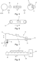
- Fig. 1 shows stacks of blanks 1 known from the prior art, each of which is held in a vertical holding device 2.
- the stacks of blanks 1 are brought closer to an automatic separating device, which pushes the lowest blank - if possible - out through an opening and thus separates the blanks.
- the blanks are then conveyed towards a press via a linear conveyor device.
- blanks can be separated and fed to a press regardless of their size and shape.
- a pile of stamped parts 5 can simply be piled onto a first conveyor 6 as a carrier 7 for receiving stamped parts 8 to be separated.
- the first conveyor device 6 is a conveyor belt with an upwardly directed support surface for stamped parts 8 to be separated, the support surface being provided with a pressure medium 9 ( Fig. 6 ) is related to a part exerts pressure on the underside of the support surface.
- the stamped parts 8 are conveyed in the conveying direction 10 on the first conveyor device 6.
- the operating state and/or the speed of the first conveyor device 6 can be controlled by a controller 11.
- the first conveyor device 6 is arranged above and in front of a means 12 for pre-metering stamped parts 8, so that a pile of stamped parts 5 can fall onto the means 12 for pre-metering by gravity.
- the means 12 for pre-dosing is a combined conveying and weighing device for detecting the originally applied weight of the punched parts 8.
- a transmitter can send the determined weight of the piles of punched parts 5 to the controller 11, which controls the operating state and / or the speed of the means 12 for pre-dosing can.
- the means 12 for pre-metering is above and in front of a means 13 for separating the punched parts 8, so that a pile of punched parts 5 can fall by gravity onto the means 13 for separating the punched parts 8.
- the means 13 for separating the stamped parts 8 comprises a conveyor device with a carrier 14 which is mounted to carry out an oscillating movement.
- the carrier 14 has a first carrier end 15 assigned to the means 12 for pre-dosing and a second carrier end 16 opposite in the longitudinal extent.
- the carrier ends 15, 16 are mounted in order to exert an upward and downward stroke and a forward and backward stroke, the stroke of the first carrier end (15) is greater than the stroke of the second carrier end (16).
- the carrier 14 is non-positively connected to the rotating element 17 via a spacer 19.
- the spacer 19 is connected to the rotating element 17 at a distance from the axis of rotation 18 of the rotating element 17, the distance from the spacer 19 to the axis of rotation 18 being changeable.
- the rotating element 17 has an elongated recess 20, along which the spacer 19 can be adjustable.
- the second support end 16 is pivotally mounted about a pivot axis 21.
- the carrier 14 has a step-like surface element 22 as a support for the stamped parts 8 to be separated, the height of which decreases from the first carrier end 15 to the second carrier end 16. It has proven to be particularly advantageous that the gradation and oscillating movement ensure material-friendly and effective separation.
- the means 13 for separating the punched parts 8 is arranged in the conveying direction 10 in front of and above a carrier 23 for receiving isolated punched parts 8, so that isolated punched parts 8 can fall onto the means 13 for separating the punched parts 8 by gravity.
- the carrier 23 for receiving isolated stamped parts 8 is a removal station 24 to which a robot 25 is assigned.
- the robot 25 removes individual stamped parts 8 and places them on a further conveyor device 26, which leads in the direction of a press 27.
- the removal station 24 always has the correct fill level of individual punched parts 8 in order to be able to continuously feed the press.
- the control can 11 control all of the aforementioned device components accordingly.
- a measuring station 28 for recording physical data of a stamped part 8 is provided.
- the measuring station 28 includes an optical measuring device 29 and lighting, which are aligned with a lateral edge of the stamped parts 8 to be measured.
- the stamped parts 8 are located in the area of the measuring station 28 on a support with a wave or meander-shaped support 30, which also enables illumination and optical measurement of the underside of the stamped parts 8.
Abstract
Eine Vorrichtung zum Bereitstellen von vereinzelten Stanzteilen (8), die vorzugsweise aus Edelmetall bestehen, für die Herstellung von Prägeprodukten hat eine Steuerung (11), ein Mittel zum Vereinzeln der Stanzteile (8) und eine Förderrichtung (10), entlang der Stanzteile (8) in Richtung zu einer Entnahmestation (24) befördert werden. Zudem hat die Vorrichtung einen Träger (7) zum Aufnehmen von zu vereinzelnden Stanzteilen (8), insbesondere von einem aufgeschütteten Stanzteilhaufen (5), ein Mittel (13) zum Vereinzeln der Stanzteile (8) umfassend eine Fördereinrichtung mit einem schwingenden Träger (14) und einen Träger (23) zum Aufnehmen von vereinzelten Stanzteilen (8).A device for providing isolated stamped parts (8), which are preferably made of precious metal, for the production of embossed products has a control (11), a means for separating the stamped parts (8) and a conveying direction (10) along the stamped parts (8 ) are transported towards a removal station (24). In addition, the device has a carrier (7) for receiving stamped parts (8) to be separated, in particular from a heap of stamped parts (5), a means (13) for separating the stamped parts (8), comprising a conveyor device with a swinging carrier (14). and a carrier (23) for holding isolated stamped parts (8).
Description
Die Erfindung betrifft eine Vorrichtung und ein Verfahren zum Bereitstellen von vereinzelten Stanzteilen, die vorzugsweise aus Edelmetall bestehen, für die Herstellung von Prägeprodukten.The invention relates to a device and a method for providing individual stamped parts, which preferably consist of precious metal, for the production of embossed products.
Zum Herstellen von Prägeprodukten, zum Beispiel Münzen, aus Edelmetall ist es bekannt, Stanzteile einer Presse, in der die Stanzteile geprägt werden, zuzuführen. Solche Stanzteile werden auch als Ronden bezeichnet. Hierfür müssen die Ronden zuvor vereinzelt werden. Wenn im Weiteren Bezug auf Ronden genommen wird, dann können damit aber jegliche Stanzteile aus Edelmetall für die Herstellung von Prägeprodukten gemeint sein, z.B. Barren oder mehreckige Teile.To produce embossed products, for example coins, from precious metal, it is known to feed stamped parts to a press in which the stamped parts are embossed. Such stamped parts are also referred to as blanks. To do this, the blanks must first be separated. If reference is made to blanks in the following, this can mean any stamped parts made of precious metal for the production of embossed products, e.g. bars or polygonal parts.
Zum Vereinzeln der Ronden ist es einerseits bekannt, dass die Ronden per Hand einzeln direkt in die Presse oder auf eine Zuführeinrichtung, insbesondere eine lineare Fördereinrichtung, aufgelegt werden. Das Auflegen auf einen Tisch, von dem aus ein Roboterarm vereinzelte Ronden entnimmt, ist nicht durchführbar, da hierbei ein erhöhtes Sicherheitsrisiko besteht und es vermieden werden muss, dass Gliedmaßen einer Person in ein Arbeitsfeld eines Roboterarmes gelangen. Das Vereinzeln von Ronden per Hand ist zudem zeit- und kostenaufwendig.To separate the blanks, it is known, on the one hand, that the blanks are placed individually by hand directly into the press or onto a feed device, in particular a linear conveyor device. Placing them on a table from which a robot arm removes individual blanks is not possible, as this poses an increased safety risk and it must be avoided that a person's limbs get into the working area of a robot arm. Separating blanks by hand is also time-consuming and costly.
Zum Vereinzeln der Ronden sind zudem Rondenstapel bekannt, die in einer vertikal ausgerichteten Halteeinrichtung gehalten sind (
Eine solche automatische Vereinzelung von Ronden aus einem Rondenstapel hat mehrere Nachteile.Such automatic separation of blanks from a stack of blanks has several disadvantages.
Zum einen ist die Höhe des Rondenstapels auf Grund des Rondenmaterials begrenzt. Auf der untersten Ronde darf nicht zu viel Gewicht liegen, da sonst die Ronde nicht mehr vereinzelt werden kann. Dieses Problem tritt insbesondere bei Goldronden auf. Goldronden können nur schwer vereinzelt und dosiert werden. Somit ist die Zuführrate an vereinzelten Ronden bereits limitiert. Zum anderen kostet es Zeit, um einen leeren Stapel von der Vereinzelungseinrichtung zu entfernen und einen neuen, vollen Stapel heranzuführen. In dieser Zeit ist demnach keine Vereinzelung möglich. Eine kontinuierliche Zufuhr von Ronden ist nicht möglich, da die Rondenzufuhr auf Grund der Stapelwechsel diskontinuierlich erfolgt.On the one hand, the height of the stack of blanks is limited due to the blank material. There should not be too much weight on the lowest blank, otherwise the blank can no longer be separated. This problem occurs particularly with gold discs. Gold blanks are difficult to separate and dose. The feed rate of individual blanks is therefore already limited. On the other hand, it takes time to remove an empty stack from the separating device and bring in a new, full stack. Isolation is therefore not possible during this time. A continuous supply of blanks is not possible because blanks are fed discontinuously due to stack changes.
Für das Bilden eines Stapels wird ein Magazin benötigt, d.h. es werden für unterschiedliche Rondentypen unterschiedliche Größen an Magazinen benötigt. Für das Füllen eines Magazins mit einem Stapel wird eine zusätzliche, externe Vorrichtung benötigt.A magazine is required to form a stack, i.e. different sizes of magazines are required for different types of blanks. An additional, external device is required to fill a magazine with a stack.
Weitere Nachteile treten abhängig von der Größe und Form der zu vereinzelnden Ronden auf.Further disadvantages arise depending on the size and shape of the blanks to be separated.
Sind die Ronden über Ihre Ober- und Unterseite bis zum Rand flach, dann liegen die Ronden auch vollflächig aufeinander auf und sind schwer zu vereinzeln. Sind die Ronden randgestaucht (
Somit ergibt sich insbesondere bei dünnen, nicht randgestauchten Ronden, die vollflächig aufeinander aufliegen, das Problem der Vereinzelung. Hier besteht das Risiko, dass mehr als eine Ronde - insbesondere zwei oder sogar mehr als zwei Ronden - zusammen aus dem Rondenstapel herausgeschoben und der Presse zugeführt werden. Dies wirkt sich dies negativ auf die Presse aus, da die Presse mit hoher Wahrscheinlichkeit beschädigt wird, wenn zwei Ronden zum Prägen zugeführt werden. Dies wirkt sich auch negativ auf die Produktion aus, da die Produktion angehalten werden muss, um die nicht vereinzelten Ronden aus der Presse zu entfernen. Dies bedingt einen Stillstand der gesamten Produktion. Dabei sinkt nicht nur die Produktivität und Anlagenverfügbarkeit, sondern verursacht auch mehr Materialausschuss, da die Ronden eben nicht mehr zum Herstellen von Prägeprodukten verwendet werden können.This results in the problem of separation, particularly with thin, edge-compressed blanks that rest on one another over the entire surface. There is a risk here that more than one blank - in particular two or even more than two blanks - are pushed out together from the stack of blanks and fed to the press. This has a negative impact on the press as the press is likely to be damaged if two blanks are fed for embossing. This also has a negative impact on production, as production has to be stopped in order to remove the unseparated blanks from the press. This causes the entire production to come to a standstill. This not only reduces productivity and system availability, but also causes more material waste because the blanks can no longer be used to produce embossed products.
Ein weiterer Nachteil bei der automatischen Vereinzelung von Rondenstapeln tritt dann auf, wenn die Ronden - wie dies häufig der Fall ist - einen Stanzgrad aufweisen (
Der Erfindung liegt die Aufgabe zu Grunde, eine Vorrichtung und ein Verfahren zum Vereinzeln von Stanzteilen aus Edelmetall zum Herstellen von Prägeprodukten zur Verfügung zu stellen, mit denen die Nachteile des Standes der Technik zumindest weitestgehend vermieden werden.The invention is based on the object of providing a device and a method for separating stamped parts made of precious metal for the production of embossed products, with which the disadvantages of the prior art are at least largely avoided.
Insbesondere ist es Aufgabe der Erfindung, eine kontinuierliche Zufuhr von Ronden zur Presse zu ermöglichen, wobei die Gefahr von Materialausschuss und von Stillstandzeiten verringert und zugleich die Produktivität und Anlagenverfügbarkeit erhöht wird.In particular, it is the object of the invention to enable a continuous supply of blanks to the press, thereby reducing the risk of material waste and downtime and at the same time increasing productivity and system availability.
Gelöst wird diese Aufgabe mit einer Vorrichtung mit den Merkmalen nach Anspruch 1 sowie mit einem Verfahren mit den Merkmalen nach Anspruch 16.This task is solved with a device with the features according to
Bevorzugte und vorteilhafte Ausführungsformen der Erfindung sind Gegenstand der Unteransprüche.Preferred and advantageous embodiments of the invention are the subject of the subclaims.
Die erfindungsgemäße Vorrichtung weist einen Träger zum Aufnehmen von Stanzteilen, insbesondere von einem aufgeschütteten Stanzteilhaufen, auf. Somit können im Rahmen der Erfindung Ronden bzw. ein ungeordneter Haufen von Ronden einfach und unabhängig von Größe und Form der Ronden aufgeschüttet werden. Das Aufschütten kann per Hand oder mechanisch erfolgen.The device according to the invention has a carrier for receiving stamped parts, in particular from a heap of stamped parts. Thus, within the scope of the invention, blanks or a disordered pile of blanks can be piled up easily and independently of the size and shape of the blanks. Filling can be done by hand or mechanically.
Die erfindungsgemäße Vorrichtung weist weiters ein Mittel zum Vereinzeln der Stanzteile umfassend eine Fördereinrichtung mit einem schwingenden Träger auf. Durch das Vereinzeln wird erzielt, dass vereinzelte Ronden dem weiteren Prozess zur Verfügung gestellt werden können, wobei das Bereitstellen von vereinzelten Ronden an die nächste Bearbeitungsstation abhängig von der benötigten Anzahl an Ronden in der Presse gesteuert werden kann.The device according to the invention further has a means for separating the stamped parts, comprising a conveyor device with a vibrating carrier. The separation ensures that isolated blanks can be made available for the further process, whereby the provision of isolated blanks to the next processing station can be controlled depending on the number of blanks required in the press.
Der Träger des Mittels zum Vereinzeln der Stanzteile ist gelagert, um eine schwingende Bewegung auszuführen, insbesondere eine oszillierende Bewegung entlang der Förderrichtung.The carrier of the means for separating the stamped parts is mounted in order to carry out an oscillating movement, in particular an oscillating movement along the conveying direction.
Durch die oszillierende und insbesondere niederfrequente (unter 30 Hz) Bewegung des Trägers werden die Ronden sowohl in Förderrichtung fördert als auch vereinzelt. Die oszillierende Bewegung des Trägers ist besonders vorteilhaft, da somit eine im Einsatzgebiet der Erfindung immanent wichtige, materialschonende Kombination aus Förderung der Ronden in Förderrichtung und Vereinzelung der Ronden erzielt werden kann.Due to the oscillating and particularly low-frequency (below 30 Hz) movement of the carrier, the blanks are both conveyed in the conveying direction and separated. The oscillating movement of the carrier is particularly advantageous because it allows a material-friendly combination of conveying the blanks in the conveying direction and separating the blanks, which is inherently important in the field of application of the invention, to be achieved.
Bekannt sind Vibrationsförderer, die durch periodische Mikrowurfbewegungen Schüttgut befördern. Solche Vibrationsförderer umfassen eine federnd eingespannte Förderfläche, die mit Hilfe von Elektromagneten in periodische Vibration versetzt wird. Durch die Vibration wird das Schüttgut durch eine überlagerte Vorwärts- und Hubbewegung angehoben, wobei das Schüttgut nach einer kurzen Flugphase wieder auf die Förderfläche auftrifft. Während der Flugphase schwingt die Förderfläche wieder in die Ausgangsposition zurück. Schnelle Vibrationsförderer arbeiten mit einer Frequenz von ca. 240 Hz. Langsame Vibrationsförderer arbeiten mit einer Frequenz von ca. 30 bis 120 Hz. Eine solche Förderung ist im Einsatzgebiet der Erfindung, insbesondere wenn es sich um Goldronden handelt, möglich aber nachteilig, da das Rondenmaterial durch die Vibration zerkratzt und beschädigt wird und durch den Materialabtrag sogenannter Flitter entsteht. Somit geht nicht nur wertvolles Material verloren, sondern der erzeugte Flitter führt dazu, dass die Vorrichtung häufig gereinigt werden muss und während dem Reinigen stillsteht.Vibration conveyors are known that transport bulk material through periodic micro-throwing movements. Such vibration conveyors include a resiliently clamped conveying surface that is set into periodic vibration with the help of electromagnets. The vibration causes the bulk material to be lifted by a superimposed forward and lifting movement, with the bulk material hitting the conveyor surface again after a short flight phase. During the flight phase, the conveyor surface swings back to the starting position. Fast vibration conveyors work at a frequency of approximately 240 Hz. Slow vibration conveyors operate at a frequency of approximately 30 to 120 Hz. Such conveyance is possible in the area of application of the invention, especially when gold blanks are involved, but is disadvantageous because the blank material is scratched and damaged by the vibration and so-called splinters are created by the material removal. Not only is valuable material lost, but the splinters generated mean that the device has to be cleaned frequently and comes to a standstill during cleaning.
Die erfindungsgemäße Vorrichtung weist zudem einen Träger zum Aufnehmen von vereinzelten Stanzteilen auf. Die Anzahl von Ronden auf diesem Träger entspricht im Rahmen der Erfindung derjenigen Anzahl, die für eine kontinuierliche Beschickung der Presse notwendig ist. Die gewünschte Anzahl der Ronden auf diesem Träger gibt im Rahmen der Erfindung die Abnahmemenge der zu vereinzelnden Ronden und der vereinzelten Ronden vor, wodurch das Mittel zum Vereinzeln der Stanzteile, ein optionales Mittel zum Vordosieren sowie gegebenenfalls eine optional vor dem Mittel zum gravimetrischen Vordosieren vorgesehene erste Fördereinrichtung gesteuert werden können.The device according to the invention also has a carrier for holding isolated stamped parts. Within the scope of the invention, the number of blanks on this carrier corresponds to the number that is necessary for continuous loading of the press. Within the scope of the invention, the desired number of blanks on this carrier specifies the quantity of blanks to be separated and the blanks to be separated, whereby the means for separating the stamped parts, an optional means for pre-metering and, if necessary, a first one optionally provided in front of the means for gravimetric pre-metering Conveyor device can be controlled.
Die Kombination der vorab genannten Merkmale ermöglicht eine materialschonende, kontinuierliche, genaue und korrekte Vereinzelung und Dosierung/Zufuhr von Ronden unabhängig von deren Größe und Gewicht, wobei die Dosierung/Zufuhr vom tatsächlichen Bedarf der Presse gesteuert werden kann. Auf bekannte Rondenstapel sowie auf die damit einhergehende Notwendigkeit des mechanischen Umbaus der Vorrichtung kann verzichtet werden.The combination of the above-mentioned features enables material-friendly, continuous, precise and correct separation and dosing/feeding of blanks regardless of their size and weight, whereby the dosage/feed can be controlled according to the actual needs of the press. Known stacks of blanks and the associated need for mechanical modification of the device can be dispensed with.
Im Rahmen der Erfindung kann vorgesehen sein, dass der Träger zum Aufnehmen von Stanzteilen durch ein Mittel zum Vordosieren gebildet ist oder durch eine in Förderrichtung davor, insbesondere unmittelbar davor und vorzugsweise überlappend darüber angeordnete, erste Fördereinrichtung. Die zuerst genannte Variante hat den Vorteil, dass der Aufbau der Vorrichtung insgesamt einfacher und somit günstiger ist. Der Vorteil der zuletzt genannten Variante liegt darin, dass bereits vor dem beispielsweise gravimetrischen Vordosieren eine gewisse Bevorratung an Ronden erzielt werden kann, was eine genaue Dosierung und kontinuierliche Zufuhr von Ronden positiv beeinflusst. Ein weiterer Vorteil der zuletzt genannten Variante besteht darin, dass die Vorrichtung automatisiert in einem geschlossenen Käfig arbeiten kann, wobei nur die erste Fördereinrichtung aus diesem Käfig herausragt. Somit können Ronden von einer Person ohne Gefahr, dass die Person mit weiteren Vorrichtungsteilen in Berührung kommt, aufgeschüttet werden, wodurch die Bediensicherheit erhöht wird.Within the scope of the invention it can be provided that the carrier for receiving stamped parts is formed by a means for pre-metering or by a first conveyor device arranged in front of it in the conveying direction, in particular immediately in front of it and preferably overlapping above it. The first-mentioned variant has the advantage that the structure of the device is simpler overall and therefore cheaper. The advantage of the last-mentioned variant is that a certain stock of blanks can be achieved before, for example, gravimetric pre-dosing, which has a positive effect on precise metering and continuous supply of blanks. A further advantage of the last-mentioned variant is that the device can work automatically in a closed cage, with only the first conveyor device protruding from this cage. This means that blanks can be piled up by one person without the risk of the person coming into contact with other parts of the device, which increases operating safety.
In einer bevorzugten Ausführungsform ist die erste Fördereinrichtung ein endloses Förderband mit einer nach oben gerichteten Auflagefläche für zu vereinzelnde Stanzteile, wobei die Auflagefläche vorzugsweise mit einem Druckmittel in Verbindung steht, das auf einen Teil der Unterseite der Auflagefläche Druck ausübt. Somit kann zwar kein Vereinzeln des aufgeschütteten Rondenhaufens erzielt werden, jedoch eine erste, grobe Verteilung.In a preferred embodiment, the first conveyor device is an endless conveyor belt with an upwardly directed support surface for stamped parts to be separated, the support surface preferably being connected to a pressure medium which exerts pressure on part of the underside of the support surface. This means that although the piled up pile of blanks cannot be separated, an initial, rough distribution can be achieved.
Das Druckmittel kann im Rahmen der Erfindung derart steuerbar sein, dass Druck in vorgegebenen periodischen Abständen oder an bestimmten Zeitpunkten abhängig vom Aufbringen von Stanzteilen ausgeübt wird.Within the scope of the invention, the pressure medium can be controllable in such a way that pressure is exerted at predetermined periodic intervals or at specific times depending on the application of stamped parts.
In einer bevorzugten Weiterbildung ist vorgesehen, dass der Betriebszustand (EIN/AUS) und/oder die Geschwindigkeit der ersten Fördereinrichtung abhängig von der Anzahl an Stanzteilen, die sich auf dem Träger zum Aufnehmen von vereinzelten Stanzteilen befinden, und somit abhängig von der Anzahl an Stanzteilen, die dem Mittel zum gravimetrischen Vordosieren zugeführt werden sollen, steuerbar ist. Dies trägt zu einem kontinuierlichen Bereitstellen von vereinzelten Ronden bei.In a preferred development it is provided that the operating state (ON/OFF) and/or the speed of the first conveyor device depends on the number of stamped parts that are on the carrier for receiving isolated stamped parts, and thus depending on the number of stamped parts , which are to be supplied to the agent for gravimetric pre-dosing, can be controlled. This contributes to the continuous provision of individual blanks.
Die auf der ersten Fördereinrichtung befindlichen Ronden können insbesondere durch Schwerkraft auf das unterhalb der ersten Fördereinrichtung angeordnete Mittel zum Vordosieren fallen.The discs located on the first conveyor device can fall, in particular by gravity, onto the pre-metering means arranged below the first conveyor device.
Im Rahmen der Erfindung ist es zudem bevorzugt, wenn das Mittel zum Vordosieren ein Mittel zum gravimetrischen Vordosieren, insbesondere eine kombinierte Förder- und Wiegeeinrichtung zum Erfassen des ursprünglich aufgebrachten Gewichtes der Stanzteile, vorzugsweise ein mit einer Waage in Verbindung stehendes Förderband ist und/oder eine Einrichtung, beispielsweise eine Kamera oder einen Sensor, zum Erfassen der ursprünglich aufgebrachten Menge der Stanzteile umfasst.Within the scope of the invention, it is also preferred if the means for pre-dosing is a means for gravimetric pre-dosing, in particular a combined conveyor and weighing device for detecting the originally applied weight of the stamped parts, preferably a conveyor belt connected to a scale and/or a Device, for example a camera or a sensor, for detecting the originally applied quantity of stamped parts.
Insbesondere wenn ein Mittel zum gravimetrischen Vordosieren ein mit einer Waage in Verbindung stehendes, endloses Förderband ist, kann eine konstruktiv einfache aber sichere Förderung und Bestimmung von Gewicht und Anzahl von zu vereinzelnden Ronden erreicht werden. Über das gemessene Gewicht kann die Anzahl der aufgebrachten Ronden bestimmt werden. Somit kann auch gesteuert werden, dass nicht zu viel und nicht zu wenig Ronden dem nachfolgenden Mittel zum Vereinzeln der Ronden zugeführt werden.In particular, if a means for gravimetric pre-dosing is an endless conveyor belt connected to a scale, a structurally simple but safe conveyance and determination of the weight and number of blanks to be separated can be achieved. The number of blanks applied can be determined via the measured weight. This means that it can also be controlled that neither too many nor too few blanks are fed to the subsequent means for separating the blanks.
Es wird demnach eine wesentliche Kennzahl erfasst, um die richtige Anzahl an Ronden bereit zu stellen.An essential key figure is therefore recorded in order to provide the correct number of blanks.
Die Kombination aus einem Mittel zum gravimetrischen Vordosieren und dem Mittel zum Vereinzeln der Stanzteile ermöglicht besonders vorteilhaft eine einfache aber materialschonende, kontinuierliche, genaue und korrekte Vereinzelung und Dosierung/Zufuhr von Ronden unabhängig von deren Größe und Gewicht, wobei die Dosierung/Zufuhr vom tatsächlichen Bedarf der Presse gesteuert werden kann.The combination of a means for gravimetric pre-dosing and the means for separating the punched parts particularly advantageously enables a simple but material-friendly, continuous, precise and correct separation and dosing/feeding of blanks regardless of their size and weight, with the dosing/feeding depending on the actual requirement the press can be controlled.
In einer bevorzugten Weiterbildung dieser Ausführungsform ist ein Sender zum Übertragen der von der Waage und/oder von der Kamera und/oder von dem Sensor ermittelten Messdaten an die Steuerung vorgesehen, so dass die Steuerung z.B. über das gemessene Gewicht ermitteln kann - beispielsweise über eine hinterlegte Tabelle mit spezifischen Gewichten von unterschiedlichen Ronden -, wie viele zu vereinzelnde Ronden sich auf dem Förderband befinden.In a preferred development of this embodiment, a transmitter is provided for transmitting the measurement data determined by the scale and/or by the camera and/or by the sensor to the controller, so that the controller can determine, for example, the measured weight - for example, via a stored one Table with specific weights of different blanks - how many blanks to be separated are on the conveyor belt.
Der Betriebszustand und/oder die Geschwindigkeit des Mittels zum gravimetrischen Vordosieren ist vorzugsweise abhängig von den von der Waage ermittelten Messdaten und abhängig von der Anzahl an Stanzteilen, die sich auf dem Träger zum Aufnehmen von vereinzelten Stanzteilen befinden, durch die Steuerung steuerbar. Dies trägt zu einem kontinuierlichen Bereitstellen von vereinzelten Ronden bei.The operating state and/or the speed of the means for gravimetric pre-dosing can preferably be controlled by the controller depending on the measurement data determined by the scale and depending on the number of stamped parts that are on the carrier for receiving isolated stamped parts. This contributes to the continuous provision of individual blanks.
Das Mittel zum Vordosieren ist vorzugsweise in Förderrichtung vor, insbesondere unmittelbar vor und vorzugsweise überlappend über dem Mittel zum Vereinzeln der Stanzteile angeordnet. Somit ist bekannt, wie viele Ronden im Weiteren vereinzelt werden sollen und die Ronden können insbesondere durch Schwerkraft auf das Mittel zum Vereinzeln der Stanzteile fallen.The means for pre-metering is preferably arranged in the conveying direction in front of, in particular immediately in front of and preferably overlapping above, the means for separating the punched parts. It is therefore known how many blanks are to be separated and the blanks can fall onto the means for separating the stamped parts, in particular due to gravity.
In einer bevorzugten Ausführungsform der Erfindung ist vorgesehen, dass der Träger des Mittels zum Vereinzeln der Stanzteile eine entlang der Förderrichtung verlaufende Längserstreckung, ein dem Mittel zum Vordosieren zugeordnetes, erstes Trägerende und ein in Längserstreckung gegenüberliegendes, zweites Trägerende aufweist, dass das erste Trägerende und vorzugsweise auch das zweite Trägerende gelagert ist, um einen Aufwärts- und Abwärtshub auszuüben, und dass das erste Trägerende und das zweite Trägerende gelagert sind, um einen Vorwärts- und Rückwärtshub auszuüben.In a preferred embodiment of the invention it is provided that the carrier of the means for separating the punched parts has a longitudinal extension running along the conveying direction, a first carrier end assigned to the means for pre-metering and a second carrier end opposite in the longitudinal extent, that the first carrier end and preferably also the second beam end is supported to exert an upward and downward stroke, and that the first beam end and the second beam end are supported to exert a forward and backward stroke.
Unter Hub wird im Rahmen der Erfindung nicht nur die reine Bewegung verstanden, sondern auch der Weg, der zwischen dem oberen und dem unteren Totpunkt bzw. den seitlichen Totpunkten zurückgelegt wird. Aufwärts- und Abwärtshub verstehen sich im Wesentlichen senkrecht zur Förderrichtung. Das zweite Trägerende muss nicht zwingend einen Aufwärts- und Abwärtshub ausüben - es ist jedoch bevorzugt, wenn zweites Trägerende dies tut, da somit die Abgabe an die Entnahmestation vereinfacht wird. Vorwärts- und Rückwärtshub verstehen sich im Wesentlichen entlang der Förderrichtung. Somit kann eine vorteilhafte Kombination aus schwingender, oszillierender und gegebenenfalls leicht (niederfrequent) vibrierender Bewegung des Trägers erzielt werden.In the context of the invention, stroke is understood to mean not only the pure movement, but also the path that is covered between the top and bottom dead centers or the side dead centers. The upward and downward strokes are essentially perpendicular to the conveying direction. The second end of the carrier does not necessarily have to exert an upward and downward stroke - however, it is preferred if the second end of the carrier does so, as this simplifies delivery to the removal station. Forward and reverse strokes are essentially along the conveying direction. An advantageous combination of oscillating, oscillating and, if necessary, slightly (low-frequency) vibrating movement of the carrier can thus be achieved.
In einer bevorzugten Weiterbildung ist vorgesehen, dass der Hub des ersten Trägerendes größer ist als der Hub des zweiten Trägerendes. Dies führt dazu, dass die Hubgeschwindigkeit in Richtung zum zweiten Ende zunimmt, wodurch der Vereinzelungseffekt erhöht wird.In a preferred development it is provided that the stroke of the first carrier end is greater than the stroke of the second carrier end. This causes the lifting speed to increase towards the second end, thereby increasing the singulation effect.
Um die im Rahmen der Erfindung bevorzugte Bewegung des Trägers zu erzielen, kann der Träger wie folgt gelagert sein:
Am ersten Trägerende kann wenigstens ein drehbar gelagertes Drehelement, insbesondere eine Scheibe oder ein Zylinder, mit einer Drehachse vorgesehen sein, wobei sich die Drehachse im Wesentlichen senkrecht zur Förderrichtung erstreckt und wobei der Träger über einen Abstandhalter mit dem Drehelement kraftschlüssig verbunden ist.In order to achieve the preferred movement of the carrier within the scope of the invention, the carrier can be mounted as follows:
At the first end of the carrier, at least one rotatably mounted rotating element, in particular a disk or a cylinder, can be provided with an axis of rotation, the axis of rotation extending essentially perpendicular to the conveying direction and the carrier being non-positively connected to the rotating element via a spacer.
Der Abstandhalter kann in einem Abstand zur Drehachse des Drehelements mit dem Drehelement verbunden sein, wobei der Abstand vom Abstandhalter zur Drehachse vorzugsweise veränderbar, insbesondere stufenlos einstellbar, ist. Durch die dezentrale Lagerung bzw. Exzentrizität wird der Hub sowohl im Wesentlichen senkrecht zur als auch in Richtung der Förderrichtung erzielt. Somit kann der Hub in alle Richtungen eingestellt werden und der Vereinzelungseffekt kann auf Ronden mit unterschiedlicher Größe und unterschiedlichem Gewicht eingestellt werden. Je exzentrischer, desto größer der Hub. Beispielsweise kann der Abstand bei kleinen, leichten Ronden verringert und bei großen, schwereren Ronden erhöht werden.The spacer can be connected to the rotating element at a distance from the axis of rotation of the rotating element, the distance from the spacer to the axis of rotation preferably being changeable, in particular continuously adjustable. Due to the decentralized storage or eccentricity, the stroke is achieved both essentially perpendicular to and in the direction of the conveying direction. This means that the stroke can be adjusted in all directions and the separation effect can be adjusted to discs of different sizes and weights. The more eccentric, the greater the stroke. For example, the distance can be reduced for small, light blanks and increased for large, heavier blanks.
Weiters kann das Drehelement eine längliche Aussparung, insbesondere eine Nut, aufweisen, die sich von einem der Drehachse zugewandten Ende (das Ende kann sich mit der Drehachse decken) zu einem der Drehachse abgewandten Ende (in Richtung zum äußeren Umfang des Drehelementes) erstreckt (beispielsweise bei einem runden Drehelement radial) und entlang (vorzugsweise innerhalb) der der Abstandhalter verstellbar festlegbar ist.Furthermore, the rotating element can have an elongated recess, in particular a groove, which extends from an end facing the axis of rotation (the end can coincide with the axis of rotation) to an end facing away from the axis of rotation (in the direction of the outer circumference of the rotating element) (for example in the case of a round rotary element radially) and along (preferably within) the spacer can be adjustable.
In einer bevorzugten Weiterbildung ist das zweite Trägerende um eine Schwenkachse schwenkbar gelagert. Vorzugsweise verläuft die Schwenkachse durch eine durchlaufende Welle oder durch einander zugeordnete Achsstummel, die insbesondere im Wesentlichen in Richtung der Förderrichtung und vorzugsweise auch im Wesentlichen senkrecht zur Förderrichtung bewegbar angeordnet ist/sind.In a preferred development, the second support end is pivotally mounted about a pivot axis. The pivot axis preferably runs through a continuous shaft or through mutually assigned axle stubs, which in particular are arranged to be movable essentially essentially in the direction of the conveying direction and preferably also essentially perpendicular to the conveying direction.
In einer besonders bevorzugten Weiterbildung ist vorgesehen, dass der Träger ein profiliertes Flächenelement als Auflage für die zu vereinzelnden Stanzteile aufweist, insbesondere ein treppenartig abgestuftes Flächenelement, dessen Höhe sich vom ersten Trägerende bis zum zweiten Trägerende verringert. Unter treppenstufig werden auch leicht sägezahnförmige Verläufe verstanden. Insbesondere werden unter treppenartigen Verläufen alle Verläufe verstanden mit einer wiederkehrenden Folge von horizontaler bzw. leicht dazu geneigter Auflagefläche für wenigstens eine Ronde gefolgt von einem Abschnitt, in dem sich im Wesentlichen die Höhe des Elementes verringert. Somit gelangen Ronden von einer Stufe in Förderrichtung zur nächsten Stufe, können aber wegen der Anschlagfläche nicht mehr zurück. Es hat sich als besonders vorteilhaft gezeigt, dass durch die Abstufung und oszillierende Bewegung ein materialschonendes und wirksames Vereinzeln stattfindet.In a particularly preferred development, it is provided that the carrier has a profiled surface element as a support for the stamped parts to be separated, in particular a stepped surface element whose height decreases from the first carrier end to the second carrier end. Staircased also includes slightly sawtooth-shaped courses. In particular, stair-like courses are understood to mean all courses with a recurring sequence of horizontal or slightly inclined support surfaces for at least one blank followed by a section in which the height of the element essentially decreases. This means that blanks move from one stage in the conveying direction to the next stage, but can no longer go back because of the stop surface. It has proven to be particularly advantageous that the gradation and oscillating movement ensure material-friendly and effective separation.
Im Rahmen der Erfindung ist es bevorzugt, wenn das Mittel zum Vereinzeln der Stanzteile in Förderrichtung vor, insbesondere unmittelbar vor und vorzugsweise überlappend über dem Träger zum Aufnehmen von vereinzelten Stanzteilen angeordnet ist. Somit können vereinzelte Ronden durch Schwerkraft auf den Träger zum Aufnehmen von vereinzelten Stanzteilen fallen. Zwischen dem Mittel zum Vereinzeln der Stanzteile und dem Träger zum Aufnehmen von vereinzelten Stanzteilen kann aber auch eine weitere Fördereinrichtung vorgesehen sein.Within the scope of the invention, it is preferred if the means for separating the punched parts in the conveying direction is arranged in front of, in particular immediately in front of and preferably overlapping over, the carrier for receiving isolated punched parts. This means that individual blanks can fall onto the carrier due to gravity to pick up individual stamped parts. However, a further conveyor device can also be provided between the means for separating the stamped parts and the carrier for receiving isolated stamped parts.
Im Rahmen der Erfindung kann der Träger zum Aufnehmen von vereinzelten Stanzteilen die Entnahmestation, insbesondere eine Entnahmestation von vereinzelten Stanzteilen durch einen Roboter, sein und einen Auflagebereich für Stanzteile, die vom Mittel zum Vereinzeln der Stanzteile zugeführt wurden, sowie einen Entnahmebereich von vereinzelt bereitgestellten Stanzteilen durch den Roboter aufweisen.Within the scope of the invention, the carrier for receiving isolated punched parts can be the removal station, in particular a removal station of isolated punched parts by a robot, and a support area for punched parts that have been supplied by the means for separating the punched parts, as well as a removal area for individually provided punched parts have the robot.
Der Träger zum Aufnehmen von vereinzelten Stanzteilen kann eine Entnahmestation zum direkten Zuführen von vereinzelten Stanzteilen zu einer Presse oder zum Zuführen von vereinzelten Stanzteilen auf eine zu einer Presse führenden Fördereinrichtung sein. Ob Ronden auf ein Förderband oder direkt in die Presse gelangen kann abhängig von der Leistung der Presse gewählt werden. Im Rahmen der Erfindung gibt Anzahl an vereinzelten Ronden auf Entnahmestation vor, wieviele Ronden auf das Mittel zum Vereinzeln der Ronden befördert und dort vereinzelt und anschließend der Entnahmestation zugeführt werden sollen.The carrier for receiving isolated stamped parts can be a removal station for directly feeding isolated stamped parts to a press or for feeding isolated stamped parts onto a conveyor device leading to a press. Whether blanks go onto a conveyor belt or directly into the press can be chosen depending on the performance of the press. Within the scope of the invention, the number of isolated blanks at the removal station specifies how many blanks should be transported to the means for separating the blanks and separated there and then fed to the removal station.
Es ist bevorzugt, wenn der Betriebszustand und/oder die Geschwindigkeit und/oder der Hub des Mittels zum Vereinzeln der Stanzteile abhängig von der Anzahl an Stanzteilen, die sich auf dem Träger zum Aufnehmen von vereinzelten Stanzteilen befinden, durch die Steuerung steuerbar ist.It is preferred if the operating state and/or the speed and/or the stroke of the means for separating the punched parts can be controlled by the controller depending on the number of punched parts that are on the carrier for receiving isolated punched parts.
In einer besonders bevorzugten Ausführungsform ist vorgesehen, dass im Bereich des Mittels zum Vereinzeln der Stanzteile, insbesondere in Förderrichtung nach dem Mittel zum Vereinzeln der Stanzteile, vorzugsweise im Übergangsbereich vom Mittel zum Vereinzeln der Stanzteile zum Träger zum Aufnehmen von vereinzelten Stanzteilen, und/oder im Bereich des Trägers zum Aufnehmen von vereinzelten Stanzteilen, vorzugsweise nach dem Träger zum Aufnehmen von vereinzelten Stanzteilen, eine Messstation zum Erfassen von physischen Daten eines Stanzteiles vorgesehen ist.In a particularly preferred embodiment it is provided that in the area of the means for separating the punched parts, in particular in the conveying direction after the means for separating the punched parts, preferably in the transition area from the means for separating the punched parts to the carrier for receiving isolated punched parts, and / or in Area of the carrier for receiving isolated stamped parts, preferably after the carrier for receiving isolated stamped parts, a measuring station for recording physical data of a stamped part is provided.
Eine solche und im weiteren näher definierte Messtation kann auch unabhängig von den bislang zur erfindungsgemäßen Vorrichtung genannten Merkmalen bzw. in beliebiger Kombination mit deren Merkmalen umgesetzt werden.Such a measuring station, which is defined in more detail below, can also be implemented independently of the features previously mentioned for the device according to the invention or in any combination with their features.
In einer bevorzugten Weiterbildung umfasst die Messstation eine optische Messeinrichtung, insbesondere eine Kamera oder einen Sensor, die die Größe und/oder die Oberflächenbeschaffenheit des Stanzteiles erfasst.In a preferred development, the measuring station comprises an optical measuring device, in particular a camera or a sensor, which records the size and/or the surface quality of the stamped part.
Wenigstens eine Messeinrichtung kann auf die Oberseite der zu vermessenden Stanzteile ausgerichtet sein. Somit kann vorgesehen sein, dass ein Höhensensor von oben auf die Oberseite eines Stanzteiles gerichtet ist, womit bereits erkannt und überprüft werden kann, ob tatsächlich eine vereinzelte Ronde vorliegt oder fälschlicherweise zwei aufeinanderliegende Ronden, die der Presse nicht zugeführt werden sollten. Ein reines Überprüfen der Ronden von oben ist jedoch bei taktzeitabhängigen Pressen nicht möglich.At least one measuring device can be aligned with the top of the stamped parts to be measured. It can therefore be provided that a height sensor is directed from above onto the top of a stamped part, which can be used to detect and check whether there is actually a single blank or whether there are incorrectly two blanks lying one on top of the other that should not be fed to the press. However, simply checking the blanks from above is not possible with cycle time-dependent presses.
Um auch eine Zufuhr von vereinzelten Stanzteilen für taktzeitabhängigen Pressen zu ermöglichen, ist bevorzugt wenigstens eine Messeinrichtung auf einen seitlichen Rand der zu vermessenden Stanzteile ausgerichtet. Vorzugsweise ist ein Beleuchtungsmittel vorgesehen, dass die Stanzteile beleuchtet. In einer bevorzugten Weiterbildung weist die Messstation einen Träger mit einer profilierten Auflage, insbesondere eine wellen- oder mäanderförmige Auflage, oder einer lichtdurchlässigen Auflage für die Stanzteile auf. Auch eine wellen- oder mäanderförmige Auflage lassen eine ausreichende Beleuchtung und somit Sichtbarkeit der Rondenoberfläche zu, da die Ronden nicht vollflächig aufliegen. Somit kann beispielsweise seitlich mit Kamera auf eine Ronde geschaut und nicht nur geprüft werden, ob die Ronde vereinzelt ist, sondern ebenfalls, ob die Ronden in der richtigen Qualität vorliegen. Insbesondere können Höhe/Dicke, Größe, Durchmesser und Ebenheit der Ronde erfasst werden.In order to also enable a supply of isolated punched parts for cycle time-dependent presses, at least one measuring device is preferably aligned with a lateral edge of the punched parts to be measured. A lighting means is preferably provided that illuminates the stamped parts. In a preferred development, the measuring station has a carrier with a profiled support, in particular a wave or meander-shaped support, or a translucent support for the stamped parts. A wave-shaped or meander-shaped support also allows sufficient illumination and thus visibility of the blank surface, since the blanks do not lie on the entire surface. This means, for example, that you can use a camera to look at a blank from the side and check not only whether the blank is isolated, but also whether the blank is of the right quality. In particular, the height/thickness, size, diameter and flatness of the blank can be recorded.
Solche Messstationen können einen wesentlichen Beitrag zur Qualitätssicherung beim Bereitstellen von vereinzelten Stanzteilen aus Edelmetall für die Herstellung von Prägeprodukten leisten.Such measuring stations can make a significant contribution to quality assurance when providing individual data Stamping parts made of precious metal for the production of embossed products.
Erfindungsgemäß ist ein Verfahren zum Bereitstellen von vereinzelten Stanzteilen, die vorzugsweise aus Edelmetall bestehen, für die Herstellung von Prägeprodukten, vorgesehen, bei dem Stanzteile vereinzelt und entlang einer Förderrichtung in Richtung zu einer Entnahmestation befördert werden, gekennzeichnet durch die folgenden Schritte:
- a) Aufbringen von Stanzteilen, insbesondere Aufschütten eines Stanzteilhaufens, auf einen Träger zum Aufnehmen von Stanzteilen,
- b) optionales Vordosieren der zu vereinzelnden Stanzteile durch ein Mittel zum Vordosieren, insbesondere Beförderung der Stanzteile in Förderrichtung und Erfassen der ursprünglich aufgebrachten Menge der Stanzteile,
- c) Vereinzeln der Stanzteile durch ein Mittel zum Vereinzeln der Stanzteile umfassend eine Fördereinrichtung mit einem schwingenden Träger,
- d) Bereitstellen der vereinzelten Stanzteile auf einem Träger zum Aufnehmen von vereinzelten Stanzteilen und
- e) Steuern zumindest der Schritte b) und c) abhängig von der Anzahl an Stanzteilen, die sich auf dem Träger zum Aufnehmen von vereinzelten Stanzteilen befinden, durch eine Steuerung.
- a) applying stamped parts, in particular heaping a pile of stamped parts, onto a carrier for receiving stamped parts,
- b) optional pre-metering of the punched parts to be separated by a means for pre-dosing, in particular conveying the punched parts in the conveying direction and recording the originally applied quantity of punched parts,
- c) separating the stamped parts by a means for separating the stamped parts comprising a conveyor device with a vibrating carrier,
- d) providing the isolated punched parts on a carrier for receiving isolated punched parts and
- e) Controlling at least steps b) and c) by a controller depending on the number of stamped parts that are on the carrier for receiving isolated stamped parts.
Weitere Einzelheiten und Merkmale der Erfindung ergeben sich aus der nachstehenden Beschreibung der Zeichnungen. Es zeigt:
- Fig. 1
- eine Draufsicht auf bekannte Rondenstapel,
- Fig. 2
- eine Seitenansicht einer randgestauchten Ronde,
- Fig. 3
- eine Seitenansicht einer Ronde mit einem Stanzgrad,
- Fig. 4
- den Aufbau einer bevorzugten Ausführungsform der erfindungsgemäßen Vorrichtung in Draufsicht,
- Fig. 5
- eine optionale Anbindung der erfindungsgemäßen Vorrichtung an eine Presse,
- Fig. 6
- eine schematische Schnittansicht einer optionalen ersten Fördereinrichtung,
- Fig. 7
- Details einer bevorzugten Ausführungsform des Mittels zum Vereinzeln der Stanzteile und
- Fig. 8
- eine schematisch dargestellte Messstation.
- Fig. 1
- a top view of well-known stacks of blanks,
- Fig. 2
- a side view of an edge-compressed blank,
- Fig. 3
- a side view of a blank with a punching grade,
- Fig. 4
- the structure of a preferred embodiment of the device according to the invention in plan view,
- Fig. 5
- an optional connection of the device according to the invention to a press,
- Fig. 6
- a schematic sectional view of an optional first conveyor device,
- Fig. 7
- Details of a preferred embodiment of the means for separating the stamped parts and
- Fig. 8
- a schematically represented measuring station.
Das Vereinzeln von Ronden ist einfacher, wenn die Ronden randgestaucht sind, da die Ronden dann an Ihren Rändern eine Stauchung 3 aufweisen (
Das Vereinzeln von Ronden ist schwieriger, wenn die Ronden - wie dies häufig der Fall ist - einen Stanzgrad 4 aufweisen (
Erfindungsgemäß können Ronden unabhängig von ihrer Größe und Form vereinzelt und einer Presse zugeführt werden.According to the invention, blanks can be separated and fed to a press regardless of their size and shape.
In dem in
Die erste Fördereinrichtung 6 ist oberhalb und vor einem Mittel 12 zum Vordosieren von Stanzteilen 8 angeordnet, so dass ein Stanzteilhaufen 5 per Schwerkraft auf das Mittel 12 zum Vordosieren fallen kann.The first conveyor device 6 is arranged above and in front of a
Das Mittel 12 zum Vordosieren ist eine kombinierte Förder- und Wiegeeinrichtung zum Erfassen des ursprünglich aufgebrachten Gewichtes der Stanzteile 8. Ein Sender kann das ermittelte Gewicht der Stanzteilhaufen 5 an die Steuerung 11 senden, die Betriebszustand und/oder die Geschwindigkeit des Mittels 12 zum Vordosieren steuern kann.The means 12 for pre-dosing is a combined conveying and weighing device for detecting the originally applied weight of the punched
Das Mittel 12 zum Vordosieren ist oberhalb und vor einem Mittel 13 zum Vereinzeln der Stanzteile 8, so dass ein Stanzteilhaufen 5 per Schwerkraft auf das einem Mittel 13 zum Vereinzeln der Stanzteile 8 fallen kann.The means 12 for pre-metering is above and in front of a
Das Mittel 13 zum Vereinzeln der Stanzteile 8 umfasst eine Fördereinrichtung mit einem Träger 14, der gelagert ist, um eine oszillierende Bewegung auszuführen. Der Träger 14 hat ein dem Mittel 12 zum Vordosieren zugeordnetes, erstes Trägerende 15 und ein in Längserstreckung gegenüberliegendes, zweites Trägerende 16. Die Trägerenden 15, 16 sind gelagert, um einen Aufwärts- und Abwärtshub und einen Vorwärts- und Rückwärtshub auszuüben, wobei der Hub des ersten Trägerendes (15) größer ist als der Hub des zweiten Trägerendes (16).The means 13 for separating the stamped
Hierfür ist im Bereich des ersten Trägerendes (15) wenigstens ein drehbar gelagertes Drehelement 17 mit einer Drehachse 18 vorgesehen (
Der Träger 14 weist ein treppenartig abgestuftes Flächenelement 22 als Auflage für die zu vereinzelnden Stanzteile 8 auf, dessen Höhe sich vom ersten Trägerende 15 bis zum zweiten Trägerende 16 verringert. Es hat sich als besonders vorteilhaft gezeigt, dass durch die Abstufung und oszillierende Bewegung ein materialschonendes und wirksames Vereinzeln stattfindet.The
Das Mittel 13 zum Vereinzeln der Stanzteile 8 ist in Förderrichtung 10 vor und über einem Träger 23 zum Aufnehmen von vereinzelten Stanzteilen 8 angeordnet, so dass vereinzelte Stanzteile 8 per Schwerkraft auf das Mittel 13 zum Vereinzeln der Stanzteile 8 fallen kann.The means 13 for separating the punched
Der Träger 23 zum Aufnehmen von vereinzelten Stanzteilen 8 ist eine Entnahmestation 24, der ein Roboter 25 zugeordnet ist. In der gezeigten Ausführungsform entnimmt der Roboter 25 vereinzelte Stanzteile 8 und legt diese auf eine weitere Fördervorrichtung 26, die in Richtung zu einer Presse 27 führt.The carrier 23 for receiving isolated stamped
Es ist eine Aufgabe der Erfindung, dass an der Entnahmestation 24 immer der richtige Füllstand an vereinzelten Stanzteilen 8 vorliegt, um die Presse kontinuierlich beschicken zu können. Abhängig vom Füllstand der Entnahmestation 24 kann die Steuerung 11 alle vorgenannten Vorrichtungskomponenten entsprechend steuern.It is an object of the invention that the removal station 24 always has the correct fill level of individual punched
Nach dem Träger 23 zum Aufnehmen von vereinzelten Stanzteilen 8 ist eine Messstation 28 zum Erfassen von physischen Daten eines Stanzteiles 8 vorgesehen. Die Messstation 28 umfasst eine optische Messeinrichtung 29 und eine Beleuchtung, die auf einen seitlichen Rand der zu vermessenden Stanzteile 8 ausgerichtet sind. Die Stanzteile 8 befinden sich im Bereich der Messstation 28 auf einem Träger mit einer wellen- oder mäanderförmigen Auflage 30, die auch eine Beleuchtung und optische Vermessung der Unterseite der Stanzteile 8 ermöglicht.After the carrier 23 for receiving isolated stamped
Claims (16)
Applications Claiming Priority (1)
| Application Number | Priority Date | Filing Date | Title |
|---|---|---|---|
| ATA50435/2022A AT526325A1 (en) | 2022-06-17 | 2022-06-17 | Device for providing individual stamped parts |
Publications (1)
| Publication Number | Publication Date |
|---|---|
| EP4292960A1 true EP4292960A1 (en) | 2023-12-20 |
Family
ID=86861690
Family Applications (1)
| Application Number | Title | Priority Date | Filing Date |
|---|---|---|---|
| EP23179801.8A Pending EP4292960A1 (en) | 2022-06-17 | 2023-06-16 | Device for providing separated stamped parts |
Country Status (2)
| Country | Link |
|---|---|
| EP (1) | EP4292960A1 (en) |
| AT (1) | AT526325A1 (en) |
Citations (12)
| Publication number | Priority date | Publication date | Assignee | Title |
|---|---|---|---|---|
| US3983388A (en) * | 1975-10-06 | 1976-09-28 | Automation Systems, Inc. | Apparatus for hardware item inspection |
| GB1507365A (en) * | 1975-03-20 | 1978-04-12 | Mullard Ltd | Object location detector |
| DE3609993A1 (en) * | 1985-03-30 | 1986-10-16 | Dipl.-Ing. Karl Bergmann GmbH, 3300 Braunschweig | Multi-track feed apparatus for mass-produced parts |
| EP0085124B1 (en) * | 1982-01-30 | 1987-11-04 | NHK SPRING CO., Ltd. | Screw inspection device |
| US5641055A (en) * | 1995-07-06 | 1997-06-24 | Carruthers Equipment Co. | Conveyor belt |
| EP1840052B1 (en) * | 2005-01-20 | 2010-08-25 | ISHIDA CO., Ltd. | Conveying device and combination metering apparatus having the same |
| JP2014052717A (en) * | 2012-09-05 | 2014-03-20 | Toshiba Tec Corp | Coin receiving and paying device, and rejection notification method |
| US20150090643A1 (en) * | 2012-05-22 | 2015-04-02 | Ig Specials B.V. | Apparatus and method for separating objects |
| US20170057026A1 (en) * | 2014-05-14 | 2017-03-02 | Tyco Electronics (Shanghai) Co. Ltd. | Electronic Apparatus Production System |
| DE102016108875A1 (en) * | 2016-05-13 | 2017-11-16 | Broetje-Automation Gmbh | Method for filling a rivet cassette with rivet elements |
| JP2019064825A (en) * | 2016-11-30 | 2019-04-25 | 共栄製作株式会社 | Vibration feeder |
| US20200101593A1 (en) * | 2018-10-02 | 2020-04-02 | Tera Automation S.R.L. | Component for feeding robots, automation systems and the like |
Family Cites Families (1)
| Publication number | Priority date | Publication date | Assignee | Title |
|---|---|---|---|---|
| US4174032A (en) * | 1977-09-06 | 1979-11-13 | Goodman Equipment Corporation | Shaker conveyor drive mechanism |
-
2022
- 2022-06-17 AT ATA50435/2022A patent/AT526325A1/en unknown
-
2023
- 2023-06-16 EP EP23179801.8A patent/EP4292960A1/en active Pending
Patent Citations (12)
| Publication number | Priority date | Publication date | Assignee | Title |
|---|---|---|---|---|
| GB1507365A (en) * | 1975-03-20 | 1978-04-12 | Mullard Ltd | Object location detector |
| US3983388A (en) * | 1975-10-06 | 1976-09-28 | Automation Systems, Inc. | Apparatus for hardware item inspection |
| EP0085124B1 (en) * | 1982-01-30 | 1987-11-04 | NHK SPRING CO., Ltd. | Screw inspection device |
| DE3609993A1 (en) * | 1985-03-30 | 1986-10-16 | Dipl.-Ing. Karl Bergmann GmbH, 3300 Braunschweig | Multi-track feed apparatus for mass-produced parts |
| US5641055A (en) * | 1995-07-06 | 1997-06-24 | Carruthers Equipment Co. | Conveyor belt |
| EP1840052B1 (en) * | 2005-01-20 | 2010-08-25 | ISHIDA CO., Ltd. | Conveying device and combination metering apparatus having the same |
| US20150090643A1 (en) * | 2012-05-22 | 2015-04-02 | Ig Specials B.V. | Apparatus and method for separating objects |
| JP2014052717A (en) * | 2012-09-05 | 2014-03-20 | Toshiba Tec Corp | Coin receiving and paying device, and rejection notification method |
| US20170057026A1 (en) * | 2014-05-14 | 2017-03-02 | Tyco Electronics (Shanghai) Co. Ltd. | Electronic Apparatus Production System |
| DE102016108875A1 (en) * | 2016-05-13 | 2017-11-16 | Broetje-Automation Gmbh | Method for filling a rivet cassette with rivet elements |
| JP2019064825A (en) * | 2016-11-30 | 2019-04-25 | 共栄製作株式会社 | Vibration feeder |
| US20200101593A1 (en) * | 2018-10-02 | 2020-04-02 | Tera Automation S.R.L. | Component for feeding robots, automation systems and the like |
Also Published As
| Publication number | Publication date |
|---|---|
| AT526325A1 (en) | 2024-01-15 |
Similar Documents
| Publication | Publication Date | Title |
|---|---|---|
| DE3617259C2 (en) | ||
| DE3800907C2 (en) | Process for destacking sheets | |
| DE2358824A1 (en) | METHOD AND DEVICE FOR APPLYING LABELS | |
| DE1786597A1 (en) | PACKAGING MACHINE FOR CIGARETTES | |
| DE60308229T2 (en) | DEVICE FOR STORING AND FEEDING PRODUCTS | |
| DE102017107586A1 (en) | weighing system | |
| DE10241798A1 (en) | Process for manufacturing folding boxes | |
| DE2126593A1 (en) | Device for measuring and packaging articles of practically the same size and shape | |
| EP3222414B1 (en) | Rotation press with stamps with at least two stamp tips at staggered heights for carrying out multiple pressing processes during a rotation | |
| EP1524087B1 (en) | Workstation | |
| EP1647373A1 (en) | Method for cutting more sides of a printed product | |
| DE2530008B2 (en) | Transport device for conveying cigarettes with a cigarette store | |
| EP4292960A1 (en) | Device for providing separated stamped parts | |
| DE2756473A1 (en) | DEVICE FOR FILLING STACKS OF PAPER IN BOXES | |
| DE2606977A1 (en) | METHOD OF DETECTING DEFECTS IN CIRCULAR TABLETS AND DEVICE FOR CARRYING OUT THE METHOD | |
| DE10126188A1 (en) | Machine for identifying components and feeding them to assembly process comprise rams lifting them out of hopper, camera above ram identifying component, e.g. by color of one face, when ram has stopped | |
| DE2905852C2 (en) | ||
| EP1290436A1 (en) | Device and method for automatically carrying out quality control of test items | |
| DE3923752A1 (en) | METHOD FOR ASSEMBLING END PIECES OF BENDING HOSES AND ROTOR FLOW STREET FOR CARRYING OUT THIS METHOD | |
| DE3018318A1 (en) | DEVICE AND METHOD FOR PERIODICALLY MOVING OBJECTS | |
| DE2047920A1 (en) | Device for separating cards from sheets of cardboard and for removing the waste surrounding the card in the sheet | |
| DE1456733A1 (en) | Device for the orderly delivery of thin stickers | |
| AT406551B (en) | Installation for sorting workpieces | |
| DE3010660A1 (en) | Automatic control system for foodstuff slicing machine - having electromagnetic clutch permitting rapid braking of motor drive, using electronic circuit with sensor, compactor and flip=flop | |
| AT503551B1 (en) | AGENT SYSTEM FOR SOLID, PARTICULARLY LOCKED PRODUCTS |
Legal Events
| Date | Code | Title | Description |
|---|---|---|---|
| PUAI | Public reference made under article 153(3) epc to a published international application that has entered the european phase |
Free format text: ORIGINAL CODE: 0009012 |
|
| STAA | Information on the status of an ep patent application or granted ep patent |
Free format text: STATUS: THE APPLICATION HAS BEEN PUBLISHED |
|
| AK | Designated contracting states |
Kind code of ref document: A1 Designated state(s): AL AT BE BG CH CY CZ DE DK EE ES FI FR GB GR HR HU IE IS IT LI LT LU LV MC ME MK MT NL NO PL PT RO RS SE SI SK SM TR |