EP4292903A2 - Child stroller frame - Google Patents
Child stroller frame Download PDFInfo
- Publication number
- EP4292903A2 EP4292903A2 EP23206915.3A EP23206915A EP4292903A2 EP 4292903 A2 EP4292903 A2 EP 4292903A2 EP 23206915 A EP23206915 A EP 23206915A EP 4292903 A2 EP4292903 A2 EP 4292903A2
- Authority
- EP
- European Patent Office
- Prior art keywords
- bar
- frame
- frame portion
- child stroller
- segment
- Prior art date
- Legal status (The legal status is an assumption and is not a legal conclusion. Google has not performed a legal analysis and makes no representation as to the accuracy of the status listed.)
- Granted
Links
Images




Classifications
-
- B—PERFORMING OPERATIONS; TRANSPORTING
- B62—LAND VEHICLES FOR TRAVELLING OTHERWISE THAN ON RAILS
- B62B—HAND-PROPELLED VEHICLES, e.g. HAND CARTS OR PERAMBULATORS; SLEDGES
- B62B7/00—Carriages for children; Perambulators, e.g. dolls' perambulators
- B62B7/04—Carriages for children; Perambulators, e.g. dolls' perambulators having more than one wheel axis; Steering devices therefor
- B62B7/06—Carriages for children; Perambulators, e.g. dolls' perambulators having more than one wheel axis; Steering devices therefor collapsible or foldable
- B62B7/064—Carriages for children; Perambulators, e.g. dolls' perambulators having more than one wheel axis; Steering devices therefor collapsible or foldable the handle bar being parallel to the front leg
-
- B—PERFORMING OPERATIONS; TRANSPORTING
- B62—LAND VEHICLES FOR TRAVELLING OTHERWISE THAN ON RAILS
- B62B—HAND-PROPELLED VEHICLES, e.g. HAND CARTS OR PERAMBULATORS; SLEDGES
- B62B7/00—Carriages for children; Perambulators, e.g. dolls' perambulators
- B62B7/04—Carriages for children; Perambulators, e.g. dolls' perambulators having more than one wheel axis; Steering devices therefor
- B62B7/06—Carriages for children; Perambulators, e.g. dolls' perambulators having more than one wheel axis; Steering devices therefor collapsible or foldable
- B62B7/10—Carriages for children; Perambulators, e.g. dolls' perambulators having more than one wheel axis; Steering devices therefor collapsible or foldable by folding down the body to the wheel carriage or by retracting projecting parts into the box-shaped body
-
- B—PERFORMING OPERATIONS; TRANSPORTING
- B62—LAND VEHICLES FOR TRAVELLING OTHERWISE THAN ON RAILS
- B62B—HAND-PROPELLED VEHICLES, e.g. HAND CARTS OR PERAMBULATORS; SLEDGES
- B62B7/00—Carriages for children; Perambulators, e.g. dolls' perambulators
- B62B7/04—Carriages for children; Perambulators, e.g. dolls' perambulators having more than one wheel axis; Steering devices therefor
- B62B7/044—Carriages for children; Perambulators, e.g. dolls' perambulators having more than one wheel axis; Steering devices therefor three wheeled
-
- B—PERFORMING OPERATIONS; TRANSPORTING
- B62—LAND VEHICLES FOR TRAVELLING OTHERWISE THAN ON RAILS
- B62B—HAND-PROPELLED VEHICLES, e.g. HAND CARTS OR PERAMBULATORS; SLEDGES
- B62B7/00—Carriages for children; Perambulators, e.g. dolls' perambulators
- B62B7/04—Carriages for children; Perambulators, e.g. dolls' perambulators having more than one wheel axis; Steering devices therefor
- B62B7/06—Carriages for children; Perambulators, e.g. dolls' perambulators having more than one wheel axis; Steering devices therefor collapsible or foldable
-
- B—PERFORMING OPERATIONS; TRANSPORTING
- B62—LAND VEHICLES FOR TRAVELLING OTHERWISE THAN ON RAILS
- B62B—HAND-PROPELLED VEHICLES, e.g. HAND CARTS OR PERAMBULATORS; SLEDGES
- B62B7/00—Carriages for children; Perambulators, e.g. dolls' perambulators
- B62B7/04—Carriages for children; Perambulators, e.g. dolls' perambulators having more than one wheel axis; Steering devices therefor
- B62B7/06—Carriages for children; Perambulators, e.g. dolls' perambulators having more than one wheel axis; Steering devices therefor collapsible or foldable
- B62B7/08—Carriages for children; Perambulators, e.g. dolls' perambulators having more than one wheel axis; Steering devices therefor collapsible or foldable in the direction of, or at right angles to, the wheel axis
-
- B—PERFORMING OPERATIONS; TRANSPORTING
- B62—LAND VEHICLES FOR TRAVELLING OTHERWISE THAN ON RAILS
- B62B—HAND-PROPELLED VEHICLES, e.g. HAND CARTS OR PERAMBULATORS; SLEDGES
- B62B7/00—Carriages for children; Perambulators, e.g. dolls' perambulators
- B62B7/04—Carriages for children; Perambulators, e.g. dolls' perambulators having more than one wheel axis; Steering devices therefor
- B62B7/14—Carriages for children; Perambulators, e.g. dolls' perambulators having more than one wheel axis; Steering devices therefor with detachable or rotatably-mounted body
Definitions
- the present invention relates to child stroller frames.
- a child stroller apparatus is generally constructed from a frame structure that can be collapsed for storage or transport and unfolded for use.
- the rear wheels may be provided with a separate folding mechanism, and a caregiver has to separately operate the stroller frame and the folding mechanism of the rear wheels for collapsing the child stroller apparatus.
- This type of stroller frames is more cumbersome in use as it requires multiple operating steps for folding the stroller apparatus.
- the folding mechanism of the rear wheels is usually placed at a lower position, the caregiver needs to bend over to operate the folding mechanism.
- the child stroller frame includes a first and a second frame portion, a pivoting part, and a linkage movably coupling the first frame portion to the pivoting part.
- the first frame portion includes a handle frame segment, a front leg segment, and a coupling part that pivotally connects the handle frame segment with the front leg segment.
- the second frame portion is pivotally connected with any of the handle frame segment, the front leg segment and the coupling part.
- the pivoting part has one end fixedly connected with a rear wheel support member and another end pivotally connected with the second frame portion.
- the linkage has a first end that is pivotally connected with any of the handle frame segment, the front leg segment and the coupling part, a second end that is pivotally connected with the pivoting part, and an intermediate portion between the first end and the second end that is pivotally connected with the second frame portion, whereby the first frame portion and the rear wheel support member are movably linked for folding in a concurrent manner toward the second frame portion.
- FIGS. 1-3 are perspective views illustrating an embodiment of a child stroller frame 100 having a foldable rear wheel.
- the child stroller frame 100 can include a first frame portion 1, a second frame portion 2, a rear wheel support member 4 coupled to a rear wheel 8, a pivoting part 3 and a linkage 5.
- the first frame portion 1 can extend upward and rearward at an angle relative to the second frame portion 2 when the child stroller frame 1 is unfolded for use, and can have a lower end provided with a front wheel 7.
- the front wheel 7 may be attached at the lower end of the first frame portion 1 and in front of the second frame portion 2.
- the second frame portion 2 can have a front end pivotally connected with the first frame portion 1 and a rear end pivotally connected with the pivoting part 3.
- the second frame portion 2 may include a tube segment at each of the left and right side of the child stroller frame 100 that is oppositely connected pivotally with the first frame portion 1 and the pivoting part 3.
- the first and second frame portions 1 and 2 can rotate relative to each other for folding and unfolding the child stroller frame 100.
- the pivoting part 3 can have an end fixedly connected with the rear wheel support member 4 and an opposite end pivotally connected with a rear end of the second frame portion 2. According to an example of construction, the pivoting part 3 may be movable as a single body. The pivoting part 3 can rotate relative to the second frame portion 2 to fold the rear wheel support member 4 carried on the pivoting part 3 toward the second frame portion 2 (the folding direction is shown with arrow P in FIG. 1 ) or unfold the rear wheel support member 4 away from the second frame portion 2.
- the linkage 5 can movably couple the first frame portion 1 to the pivoting part 3, whereby the first frame portion 1 and the rear wheel support member 4 carried on the pivoting part 3 are movably linked for folding in a concurrent manner toward the second frame portion 2 or unfolding in a concurrently manner away from the second frame portion 2. More specifically, the linkage 5 can have a first and a second end opposite to each other that are respectively coupled to the first frame portion 1 and the pivoting part 3, and an intermediate portion between the first and second ends that is pivotally connected with the second frame portion 2.
- the pivoting part 3 with the rear wheel support member 4 carried thereon can rotate and fold toward the second frame portion 2 owing to the coupling of the linkage 5. Accordingly, the rear wheel support member 4 and the rear wheel 8 provided thereon can be conveniently folded along with the folding of the child stroller frame 100 without the need for a caregiver to perform an additional step of bending over and operating the rear wheel 8.
- the first frame portion 1 includes a handle frame segment 11 and a front leg segment 12 pivotally connected with each other.
- the second frame portion 2 has a front end that may be pivotally connected with any of the handle frame segment 11, the front leg segment 12, or a coupling part 13 that pivotally connects the handle frame segment 11 with the front leg segment 12;
- the linkage 5 has a first end that may be pivotally connected with any of the handle frame segment 11, the front leg segment 12 or the coupling part 13, a second end that is pivotally connected with the pivoting part 3, and an intermediate portion between the first and second ends that is pivotally connected with the second frame portion 2.
- the front end of the second frame portion 2 is pivotally connected with the front leg segment 12 adjacent to a front wheel mounting portion 14 thereof, and the first end of the linkage 5 is pivotally connected with the front leg segment 12.
- the front leg segment 12 can rotate and fold toward the second frame portion 2 while the handle frame segment 11 and the front leg segment 12 can rotationally fold over each other.
- the handle frame segment 11 and the front leg segment 12 can thereby fold to lie at one same side of the second frame portion 2.
- the pivoting part 3 with the rear wheel support member 4 carried thereon can be urged to rotate concurrently and fold toward the second frame portion 2 owing to the coupling of the linkage 5.
- the child stroller frame 100 may be possible.
- the handle frame segment 11 can rotate in an anticlockwise direction (i.e., corresponding to the direction P in FIG. 1 ) relative to the second frame portion 2 and fold toward the second frame portion 2, while the front leg segment 12 can rotate in a clockwise direction (i.e., opposite to the direction P) relative to the second frame portion 2 and fold toward the second frame portion 2.
- the handle frame segment 11 and the front leg segment 12 can thereby fold to respectively lie at two opposite sides of the second frame portion 2. As the handle frame segment 11 and the front leg segment 12 are folded toward the second frame portion 2, the linkage 5 can likewise cause the rear wheel support member 4 and the rear wheel 8 provided thereon to fold toward the second frame portion 2.
- the rear wheel support member 4 described herein can provide support for attachment of the rear wheel 8.
- the rear wheel support member 4 may include a transversal axle to which are attached two rear wheels 8.
- the rear wheel support member 4 may include a wheel mount to which is attached one rear wheel 8, two separate sets of the rear wheel support member 4 and the rear wheel 8 being respectively provided at the left and right sides of the second frame portion 2.
- the linkage 5 can include a first bar assembly 51 and a second bar assembly 52.
- the first bar assembly 51 can be respectively connected pivotally with the second frame portion 2 and the pivoting part 3, wherein the first bar assembly 51, the pivoting part 3 and the second frame portion 2 can be configured to form a first bar linkage portion.
- the second bar assembly 52 can be respectively coupled to the first bar assembly 51 and the first frame portion 1.
- the first bar assembly 51 can include a first bar 511 pivotally connected with the second frame portion 2, and the second bar assembly 52 can be respectively connected pivotally with the first bar 511 and the first frame portion 1.
- the second bar assembly 52, the first bar 511, the first frame portion 1 and the second frame portion 2 can be configured to form a second bar linkage portion.
- a relative rotation between the first frame portion 1 and the second frame portion 2 in a folding direction causes the first bar 511 to rotate relative to the second frame portion 2, which results in the first bar linkage portion to fold and the pivoting part 3 to rotate for folding the rear wheel support member 4 toward the second frame portion 2.
- the first and second bar assemblies 51 and 52 are operable to drive the rear wheel support member 4 to fold toward the second frame portion 2 when the first frame portion 1 rotates relative to the second frame portion 2 in a folding direction.
- the first bar assembly 51 and the second bar assembly 52 may be located at an inner side of the pivoting part 3 to prevent environment interference during use.
- two sets of the first and second bar assemblies 51 and 52 can be symmetrically provided at the left and right sides of the child stroller frame 100.
- the child stroller frame 100 may further include a seat mount 6 for installation of a detachable child seat 200.
- the installed child seat 200 may be collapsed along with the child stroller frame 100 into a compact form at an inner side of the child stroller frame 100.
- the first bar assembly 51 can include a plurality of bars.
- the first bar assembly 51, the second frame portion 2 and the pivoting part 3 are configured to form a first bar linkage portion adapted to fold the pivoting part 3 and the rear wheel support member 4 carried thereon toward the second frame portion 2 during folding of the child stroller frame 100.
- the first bar assembly 51, the second frame portion 2 and the pivoting part 3 may be configured to form a four-bar linkage.
- the first bar assembly 51 can include the first bar 511 and a second bar 512, the second bar 512 having two opposite ends respectively connected pivotally with the first bar 511 and the pivoting part 3.
- the first and second bars 511 and 512 of the first bar assembly 51, the second frame portion 2 and the pivoting part 3 can form the first bar linkage portion that is operable to cause the pivoting part 3 and the rear wheel 8 carried thereon to fold toward the second frame portion 2. More specifically, a rotation of the first bar 511 relative to the second frame portion 2 in a folding direction can cause the second bar 512 to move and urge the pivoting part 3 to rotate relative to the second frame portion 2 in the direction P for folding toward the second frame portion 2.
- the second bar 512 can have a shape 5121 configured to achieve compact folding and prevent obstructing interference with the pivoting part 3 and/or the rear wheel support member 4 during folding movement.
- the shape 5121 of the second bar 512 may include a curved profile with a concavity facing downward.
- the second bar assembly 52 can include one or a plurality of bars.
- the second bar assembly 52, the first bar 511, the first frame portion 1 and the second frame portion 2 can be configured to form a second bar linkage portion.
- the second bar linkage portion may be a four-bar linkage.
- the second bar assembly 52 can include a third bar 521 having two opposite ends respectively connected pivotally with the first bar 511 and the first frame portion 1.
- the first bar 511, the third bar 521, the first frame portion 1 and the second frame portion 2 can thereby form the second bar linkage portion.
- the first bar 511 can have two bar portions 5111 and 5112 that intersect each other at an angle.
- the first bar 511 including the bar portions 5111 and 5112 may be formed integrally as a single body.
- the bar portion 5111 may have an elongate shape with a length greater than the length of the bar portion 5112.
- the first bar 511 can be pivotally connected with the second bar assembly 52 at an end of the bar portion 5111, and the bar portion 5112 can extend at an angle from the bar portion 5111 toward the second bar 512 and pivotally connect with the second bar 512.
- the second bar 512 has a nonlinear shape, and the shape and/or length of the bar portion 5112 may be configured in accordance with the desired folding shape of the first and second bars 511 and 512 so that the first bar linkage portion can be collapsed into a smaller volume.
- the pivot connection between the first bar 511 and the second frame portion 2 can be located at the joining region between the two bar portions 5111 and 5112.
- the bar portion 5112 of the first bar 511, the second bar 512, the second frame portion 2 and the pivoting part 3 can form a first bar linkage portion; the bar portion 5111 of the first bar 511, the third bar 521, the second frame portion 2 and the first frame portion 1 can form a second bar linkage portion.
- a limiting structure 53 can be disposed between the bar portion 5111 and the second bar assembly 52.
- the limiting structure 53 can include a limiting joint pivotally coupling the bar portion 5111 of the first bar 511 to the third bar 521.
- the bar portion 5111 of the first bar 511 and the second bar assembly 52 (in particular the third bar 521 thereof) can form a substantially straight shape that extends between the first frame portion 1 and the second frame portion 2 and can provide stable support for the first frame portion 1.
- the first bar 511 can have a L-shape.
- the first frame portion 1 can be rotated for folding relative to the second frame portion 2. More specifically, the front leg segment 12 can rotate and fold toward the second frame portion 2, which results in folding of the second bar linkage portion. As the second bar linkage folds, the first bar 511 rotates relative to the second frame portion 2, which actuates the first bar linkage portion so that the pivoting part 3 rotates in the direction P and folds toward the second frame portion 2. As a result, the rear wheel support member 4 can be displaced by the pivoting part 3 to a position adjacent to the second frame portion 2 and in front of the pivot connection between the second frame portion 2 and the pivoting part 3. Moreover, the handle frame segment 11 can rotate and fold over the front leg segment 12 so that the size of the first frame portion 1 can be reduced and the child seat 200 can be positioned compactly at an inner side of the folded child stroller frame 100.
- the handle frame segment 11, the front leg segment 12 and the second frame portion 2 can be reversely rotated relative to one another, which causes the pivoting part 3 to rotate and unfold from the second frame portion 2 owing to the first and second bar linkage portions.
- the rear wheel support member 4 can be displaced by the pivoting part 3 to a position away from the second frame portion 2 and behind the pivot connection between the second frame portion 2 and the pivoting part 3.
- the rear wheel support member 4 Since the rear wheel support member 4 is movably linked to the child stroller frame 100, the rear wheel support member 4 may be held in the unfolded or folded state without the need of providing an additional locking mechanism for locking the rear wheel support member 4 in position relative to the second frame portion 2.
- Advantages of the structures described herein include the ability to provide a child stroller frame that has a foldable rear wheel support member, whereby the child stroller frame can be folded into a compact form.
- the rear wheel support member can be movably coupled to the other frame portions of the child stroller frame with a linkage, thereby allowing the entire stroller frame to fold and unfold in a convenient manner.
Landscapes
- Engineering & Computer Science (AREA)
- Chemical & Material Sciences (AREA)
- Combustion & Propulsion (AREA)
- Transportation (AREA)
- Mechanical Engineering (AREA)
- Carriages For Children, Sleds, And Other Hand-Operated Vehicles (AREA)
- Motorcycle And Bicycle Frame (AREA)
Abstract
Description
- This application is a divisional application of
EP application no. 20700451.6 having an EP entry date of June 23, 2021 Chinese patent application no. 201910019182.X filed on January 8, 2019 - The present invention relates to child stroller frames.
- A child stroller apparatus is generally constructed from a frame structure that can be collapsed for storage or transport and unfolded for use. In some existing stroller frame structures, the rear wheels may be provided with a separate folding mechanism, and a caregiver has to separately operate the stroller frame and the folding mechanism of the rear wheels for collapsing the child stroller apparatus. This type of stroller frames is more cumbersome in use as it requires multiple operating steps for folding the stroller apparatus. Moreover, because the folding mechanism of the rear wheels is usually placed at a lower position, the caregiver needs to bend over to operate the folding mechanism.
- Therefore, there is a need for an improved stroller frame that can be more convenient in use and address at least the foregoing issues.
- The present application describes a child stroller frame that can be folded and unfolded in a convenient manner. According to one aspect, the child stroller frame includes a first and a second frame portion, a pivoting part, and a linkage movably coupling the first frame portion to the pivoting part. The first frame portion includes a handle frame segment, a front leg segment, and a coupling part that pivotally connects the handle frame segment with the front leg segment. The second frame portion is pivotally connected with any of the handle frame segment, the front leg segment and the coupling part. The pivoting part has one end fixedly connected with a rear wheel support member and another end pivotally connected with the second frame portion. The linkage has a first end that is pivotally connected with any of the handle frame segment, the front leg segment and the coupling part, a second end that is pivotally connected with the pivoting part, and an intermediate portion between the first end and the second end that is pivotally connected with the second frame portion, whereby the first frame portion and the rear wheel support member are movably linked for folding in a concurrent manner toward the second frame portion.
-
-
FIG. 1 is a perspective view illustrating an embodiment of a child stroller frame in an unfolded state; -
FIG. 2 is a perspective view illustrating the child stroller frame ofFIG. 1 in a partially folded state; -
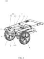
FIG. 3 is a perspective view illustrating the child stroller frame ofFIG. 1 in a fully folded state; -
FIG. 4 is a side view illustrating the child stroller frame in the unfolded state with a child seat installed thereon; and -
FIG. 5 is a side view illustrating the child stroller frame in the fully folded state with the child seat installed thereon. -
FIGS. 1-3 are perspective views illustrating an embodiment of achild stroller frame 100 having a foldable rear wheel. Referring toFIGS. 1-3 , thechild stroller frame 100 can include afirst frame portion 1, asecond frame portion 2, a rearwheel support member 4 coupled to arear wheel 8, a pivotingpart 3 and alinkage 5. - The
first frame portion 1 can extend upward and rearward at an angle relative to thesecond frame portion 2 when thechild stroller frame 1 is unfolded for use, and can have a lower end provided with afront wheel 7. Thefront wheel 7 may be attached at the lower end of thefirst frame portion 1 and in front of thesecond frame portion 2. - The
second frame portion 2 can have a front end pivotally connected with thefirst frame portion 1 and a rear end pivotally connected with thepivoting part 3. According to an example of construction, thesecond frame portion 2 may include a tube segment at each of the left and right side of thechild stroller frame 100 that is oppositely connected pivotally with thefirst frame portion 1 and thepivoting part 3. The first andsecond frame portions child stroller frame 100. - The pivoting
part 3 can have an end fixedly connected with the rearwheel support member 4 and an opposite end pivotally connected with a rear end of thesecond frame portion 2. According to an example of construction, thepivoting part 3 may be movable as a single body. The pivotingpart 3 can rotate relative to thesecond frame portion 2 to fold the rearwheel support member 4 carried on the pivotingpart 3 toward the second frame portion 2 (the folding direction is shown with arrow P inFIG. 1 ) or unfold the rearwheel support member 4 away from thesecond frame portion 2. - The
linkage 5 can movably couple thefirst frame portion 1 to the pivotingpart 3, whereby thefirst frame portion 1 and the rearwheel support member 4 carried on the pivotingpart 3 are movably linked for folding in a concurrent manner toward thesecond frame portion 2 or unfolding in a concurrently manner away from thesecond frame portion 2. More specifically, thelinkage 5 can have a first and a second end opposite to each other that are respectively coupled to thefirst frame portion 1 and thepivoting part 3, and an intermediate portion between the first and second ends that is pivotally connected with thesecond frame portion 2. When thefirst frame portion 1 and thesecond frame portion 2 rotate relative to each other for folding thechild stroller frame 100, the pivotingpart 3 with the rearwheel support member 4 carried thereon can rotate and fold toward thesecond frame portion 2 owing to the coupling of thelinkage 5. Accordingly, the rearwheel support member 4 and therear wheel 8 provided thereon can be conveniently folded along with the folding of thechild stroller frame 100 without the need for a caregiver to perform an additional step of bending over and operating therear wheel 8. - According to an embodiment, the
first frame portion 1 includes ahandle frame segment 11 and afront leg segment 12 pivotally connected with each other. Thesecond frame portion 2 has a front end that may be pivotally connected with any of thehandle frame segment 11, thefront leg segment 12, or acoupling part 13 that pivotally connects thehandle frame segment 11 with thefront leg segment 12; thelinkage 5 has a first end that may be pivotally connected with any of thehandle frame segment 11, thefront leg segment 12 or thecoupling part 13, a second end that is pivotally connected with thepivoting part 3, and an intermediate portion between the first and second ends that is pivotally connected with thesecond frame portion 2. - In the example shown in
FIG. 1 , the front end of thesecond frame portion 2 is pivotally connected with thefront leg segment 12 adjacent to a frontwheel mounting portion 14 thereof, and the first end of thelinkage 5 is pivotally connected with thefront leg segment 12. During folding of thechild stroller frame 100, thefront leg segment 12 can rotate and fold toward thesecond frame portion 2 while thehandle frame segment 11 and thefront leg segment 12 can rotationally fold over each other. Thehandle frame segment 11 and thefront leg segment 12 can thereby fold to lie at one same side of thesecond frame portion 2. Moreover, the pivotingpart 3 with the rearwheel support member 4 carried thereon can be urged to rotate concurrently and fold toward thesecond frame portion 2 owing to the coupling of thelinkage 5. - It will be appreciated that other constructions of the
child stroller frame 100 may be possible. For example, suppose the front end of thesecond frame portion 2 is pivotally connected with thecoupling part 13 that pivotally connects thehandle frame segment 11 with thefront leg segment 12. The first end of thelinkage 5 can be pivotally connected with thefront leg segment 12 or thehandle frame segment 11. During folding of thechild stroller frame 100, thehandle frame segment 11 can rotate in an anticlockwise direction (i.e., corresponding to the direction P inFIG. 1 ) relative to thesecond frame portion 2 and fold toward thesecond frame portion 2, while thefront leg segment 12 can rotate in a clockwise direction (i.e., opposite to the direction P) relative to thesecond frame portion 2 and fold toward thesecond frame portion 2. Thehandle frame segment 11 and thefront leg segment 12 can thereby fold to respectively lie at two opposite sides of thesecond frame portion 2. As thehandle frame segment 11 and thefront leg segment 12 are folded toward thesecond frame portion 2, thelinkage 5 can likewise cause the rearwheel support member 4 and therear wheel 8 provided thereon to fold toward thesecond frame portion 2. - The rear
wheel support member 4 described herein can provide support for attachment of therear wheel 8. Various constructions may be applied for the rearwheel support member 4. According to an example of construction, the rearwheel support member 4 may include a transversal axle to which are attached tworear wheels 8. According to another example of construction, the rearwheel support member 4 may include a wheel mount to which is attached onerear wheel 8, two separate sets of the rearwheel support member 4 and therear wheel 8 being respectively provided at the left and right sides of thesecond frame portion 2. - Referring to
FIGS. 1-3 , thelinkage 5 can include afirst bar assembly 51 and asecond bar assembly 52. Thefirst bar assembly 51 can be respectively connected pivotally with thesecond frame portion 2 and thepivoting part 3, wherein thefirst bar assembly 51, thepivoting part 3 and thesecond frame portion 2 can be configured to form a first bar linkage portion. Thesecond bar assembly 52 can be respectively coupled to thefirst bar assembly 51 and thefirst frame portion 1. For example, thefirst bar assembly 51 can include afirst bar 511 pivotally connected with thesecond frame portion 2, and thesecond bar assembly 52 can be respectively connected pivotally with thefirst bar 511 and thefirst frame portion 1. Thesecond bar assembly 52, thefirst bar 511, thefirst frame portion 1 and thesecond frame portion 2 can be configured to form a second bar linkage portion. A relative rotation between thefirst frame portion 1 and thesecond frame portion 2 in a folding direction causes thefirst bar 511 to rotate relative to thesecond frame portion 2, which results in the first bar linkage portion to fold and the pivotingpart 3 to rotate for folding the rearwheel support member 4 toward thesecond frame portion 2. In other words, the first and second bar assemblies 51 and 52 are operable to drive the rearwheel support member 4 to fold toward thesecond frame portion 2 when thefirst frame portion 1 rotates relative to thesecond frame portion 2 in a folding direction. - Referring to
FIGS. 1-3 , thefirst bar assembly 51 and thesecond bar assembly 52 may be located at an inner side of the pivotingpart 3 to prevent environment interference during use. According to an example of construction, two sets of the first andsecond bar assemblies child stroller frame 100. Moreover, thechild stroller frame 100 may further include aseat mount 6 for installation of adetachable child seat 200. The installedchild seat 200 may be collapsed along with thechild stroller frame 100 into a compact form at an inner side of thechild stroller frame 100. - Referring to
FIGS. 1-3 , thefirst bar assembly 51 can include a plurality of bars. Thefirst bar assembly 51, thesecond frame portion 2 and the pivotingpart 3 are configured to form a first bar linkage portion adapted to fold the pivotingpart 3 and the rearwheel support member 4 carried thereon toward thesecond frame portion 2 during folding of thechild stroller frame 100. For example, thefirst bar assembly 51, thesecond frame portion 2 and the pivotingpart 3 may be configured to form a four-bar linkage. According to an example of construction, thefirst bar assembly 51 can include thefirst bar 511 and asecond bar 512, thesecond bar 512 having two opposite ends respectively connected pivotally with thefirst bar 511 and the pivotingpart 3. The first andsecond bars first bar assembly 51, thesecond frame portion 2 and the pivotingpart 3 can form the first bar linkage portion that is operable to cause the pivotingpart 3 and therear wheel 8 carried thereon to fold toward thesecond frame portion 2. More specifically, a rotation of thefirst bar 511 relative to thesecond frame portion 2 in a folding direction can cause thesecond bar 512 to move and urge the pivotingpart 3 to rotate relative to thesecond frame portion 2 in the direction P for folding toward thesecond frame portion 2. Thesecond bar 512 can have ashape 5121 configured to achieve compact folding and prevent obstructing interference with the pivotingpart 3 and/or the rearwheel support member 4 during folding movement. For example, theshape 5121 of thesecond bar 512 may include a curved profile with a concavity facing downward. - Referring to
FIGS. 1-3 , thesecond bar assembly 52 can include one or a plurality of bars. Thesecond bar assembly 52, thefirst bar 511, thefirst frame portion 1 and thesecond frame portion 2 can be configured to form a second bar linkage portion. According to an example of construction, the second bar linkage portion may be a four-bar linkage. For example, thesecond bar assembly 52 can include athird bar 521 having two opposite ends respectively connected pivotally with thefirst bar 511 and thefirst frame portion 1. Thefirst bar 511, thethird bar 521, thefirst frame portion 1 and thesecond frame portion 2 can thereby form the second bar linkage portion. - Referring to
FIGS. 1-3 , thefirst bar 511 can have twobar portions first bar 511 including thebar portions bar portion 5111 may have an elongate shape with a length greater than the length of thebar portion 5112. Thefirst bar 511 can be pivotally connected with thesecond bar assembly 52 at an end of thebar portion 5111, and thebar portion 5112 can extend at an angle from thebar portion 5111 toward thesecond bar 512 and pivotally connect with thesecond bar 512. According to an example of construction, thesecond bar 512 has a nonlinear shape, and the shape and/or length of thebar portion 5112 may be configured in accordance with the desired folding shape of the first andsecond bars first bar 511 and thesecond frame portion 2 can be located at the joining region between the twobar portions bar portion 5112 of thefirst bar 511, thesecond bar 512, thesecond frame portion 2 and the pivotingpart 3 can form a first bar linkage portion; thebar portion 5111 of thefirst bar 511, thethird bar 521, thesecond frame portion 2 and thefirst frame portion 1 can form a second bar linkage portion. - Moreover, a limiting
structure 53 can be disposed between thebar portion 5111 and thesecond bar assembly 52. According to an example of construction, the limitingstructure 53 can include a limiting joint pivotally coupling thebar portion 5111 of thefirst bar 511 to thethird bar 521. When thechild stroller frame 100 is in an unfolded state for use, thebar portion 5111 of thefirst bar 511 and the second bar assembly 52 (in particular thethird bar 521 thereof) can form a substantially straight shape that extends between thefirst frame portion 1 and thesecond frame portion 2 and can provide stable support for thefirst frame portion 1. According to an example of construction, thefirst bar 511 can have a L-shape. - Exemplary operation of the
child stroller frame 100 is described hereinafter with reference toFIGS. 1-5 . When thechild stroller frame 100 is to be collapsed, thefirst frame portion 1 can be rotated for folding relative to thesecond frame portion 2. More specifically, thefront leg segment 12 can rotate and fold toward thesecond frame portion 2, which results in folding of the second bar linkage portion. As the second bar linkage folds, thefirst bar 511 rotates relative to thesecond frame portion 2, which actuates the first bar linkage portion so that the pivotingpart 3 rotates in the direction P and folds toward thesecond frame portion 2. As a result, the rearwheel support member 4 can be displaced by the pivotingpart 3 to a position adjacent to thesecond frame portion 2 and in front of the pivot connection between thesecond frame portion 2 and the pivotingpart 3. Moreover, thehandle frame segment 11 can rotate and fold over thefront leg segment 12 so that the size of thefirst frame portion 1 can be reduced and thechild seat 200 can be positioned compactly at an inner side of the foldedchild stroller frame 100. - When the
child stroller frame 100 is to be unfolded for use, thehandle frame segment 11, thefront leg segment 12 and thesecond frame portion 2 can be reversely rotated relative to one another, which causes the pivotingpart 3 to rotate and unfold from thesecond frame portion 2 owing to the first and second bar linkage portions. As a result, the rearwheel support member 4 can be displaced by the pivotingpart 3 to a position away from thesecond frame portion 2 and behind the pivot connection between thesecond frame portion 2 and the pivotingpart 3. - Since the rear
wheel support member 4 is movably linked to thechild stroller frame 100, the rearwheel support member 4 may be held in the unfolded or folded state without the need of providing an additional locking mechanism for locking the rearwheel support member 4 in position relative to thesecond frame portion 2. - Advantages of the structures described herein include the ability to provide a child stroller frame that has a foldable rear wheel support member, whereby the child stroller frame can be folded into a compact form. The rear wheel support member can be movably coupled to the other frame portions of the child stroller frame with a linkage, thereby allowing the entire stroller frame to fold and unfold in a convenient manner.
- Further, the following embodiments are described herein:
-
Embodiment 1. A child stroller frame comprising: a first and a second frame portion, the second frame portion having a front end and a rear end, the front end of the second frame portion being pivotally connected with the first frame portion; a pivoting part having one end fixedly connected with a rear wheel support member and another end pivotally connected with the rear end of the second frame portion; and a linkage movably coupling the first frame portion to the pivoting part, the linkage having an intermediate portion pivotally connected with the second frame portion, whereby the first frame portion and the rear wheel support member are movably linked for folding in a concurrent manner toward the second frame portion. -
Embodiment 2. The child stroller frame according toembodiment 1, wherein the first frame portion includes a handle frame segment and a front leg segment that are pivotally connected with each other. -
Embodiment 3. The child stroller frame according toembodiment 2, wherein the second frame portion is pivotally connected with any of the front leg segment, the handle frame segment, or a coupling part that pivotally connects the front leg segment with the handle frame segment. -
Embodiment 4. The child stroller frame according toembodiment 2, wherein the linkage has an end that is pivotally connected with any of the front leg segment, the handle frame segment, or a coupling part that pivotally connects the front leg segment with the handle frame segment. -
Embodiment 5. The child stroller frame according toembodiment 2, wherein the child stroller frame is folded either with the handle frame segment and the front leg segment lying at one same side of the second frame portion, or with the handle frame segment and the front leg segment respectively lying at two opposite sides of the second frame portion. -
Embodiment 6. The child stroller frame according to any one ofembodiments 1 to 5, wherein the linkage includes: a first bar assembly respectively connected pivotally with the pivoting part and the second frame portion, the first bar assembly including a first bar pivotally connected with the second frame portion, wherein the first bar assembly, the pivoting part and the second frame portion form a first bar linkage portion; and a second bar assembly respectively connected pivotally with the first bar and the first frame portion, wherein the second bar assembly, the first bar, the first frame portion and the second frame portion form a second bar linkage portion. -
Embodiment 7. The child stroller frame according toembodiment 6, wherein the first bar assembly includes a second bar having two opposite ends respectively connected pivotally with the first bar and the pivoting part. -
Embodiment 8. The child stroller frame according toembodiment 7, wherein the first bar has a first and a second bar portion, the first bar being pivotally connected with the second bar assembly at an end of the first bar portion, and the second bar portion extending toward and pivotally connecting with the second bar. - Embodiment 9. The child stroller frame according to
embodiment 8, wherein the first and second bar portions intersect each other at an angle, a pivot connection between the first bar and the second frame portion being located at a joining region between the first and second bar portions. - Embodiment 10. The child stroller frame according to
embodiment 8 or 9, wherein the first bar has a L-shape. -
Embodiment 11. The child stroller frame according toembodiment 8, 9 or 10, further including a limiting structure disposed between the first bar portion and the second bar assembly, the first bar portion and the second bar assembly forming a substantially straight shape that extends between the first frame portion and the second frame portion when the child stroller frame is in an unfolded state for use. -
Embodiment 12. The child stroller frame according to any one ofembodiments 7 to 11, wherein the second bar has a shape configured to prevent obstructing interference with the pivoting part and/or the rear wheel support member during folding movement. -
Embodiment 13. The child stroller frame according toembodiment 12, wherein the second bar includes a curved profile with a concavity facing downward. -
Embodiment 14. The child stroller frame according to any one ofembodiments 6 to 13, wherein the second bar assembly includes a third bar having two opposite ends respectively connected pivotally with the first bar and the first frame portion. - Embodiment 15. The child stroller frame according to any one of
embodiments 1 to 14, wherein the rear wheel support member includes a transversal axle or a wheel mount. - Realization of the child stroller frame has been described in the context of particular embodiments. These embodiments are meant to be illustrative and not limiting. Many variations, modifications, additions, and improvements are possible. These and other variations, modifications, additions, and improvements may fall within the scope of the inventions as defined in the claims that follow.
Claims (14)
- A child stroller frame (100) comprising:a first frame portion (1) including a handle frame segment (11), a front leg segment (12), and a coupling part (13) that pivotally connects the handle frame segment (11) with the front leg segment (12);a second frame portion (2) pivotally connected with any of the handle frame segment (11), the front leg segment (12) and the coupling part (13);a pivoting part (3) having one end fixedly connected with a rear wheel support member (4) and another end pivotally connected with the second frame portion (2); anda linkage (5) movably coupling the first frame portion (1) to the pivoting part (3), the linkage (5) having a first end that is pivotally connected with any of the handle frame segment (11), the front leg segment (12) and the coupling part (13), a second end that is pivotally connected with the pivoting part (3), and an intermediate portion between the first end and the second end that is pivotally connected with the second frame portion (2), whereby the first frame portion (1) and the rear wheel support member (4) are movably linked for folding in a concurrent manner toward the second frame portion (2).
- The child stroller frame (100) according to claim 1, wherein the child stroller frame (100) is folded either with the handle frame segment (11) and the front leg segment (12) lying at one same side of the second frame portion (2), or with the handle frame segment (11) and the front leg segment (12) respectively lying at two opposite sides of the second frame portion (2).
- The child stroller frame (100) according to claim 1 or 2, wherein the second frame portion (2) has a front end pivotally connected with the front leg segment (12), and a rear end pivotally connected with the pivoting part (3).
- The child stroller frame (100) according to claim 1 or 2, wherein the second frame portion (2) has a front end pivotally connected with the coupling part (13), and the first end of the linkage (5) is pivotally connected with the front leg segment (12) or the handle frame segment (11).
- The child stroller frame (100) according to any of claims 1 to 4, wherein the linkage (5) includes:a first bar assembly (51) respectively connected pivotally with the pivoting part (3) and the second frame portion (2), the first bar assembly (51) including a first bar (511) pivotally connected with the second frame portion (2); anda second bar assembly (52) respectively connected pivotally with the first bar (511) and the first frame portion (1).
- The child stroller frame (100) according to claim 5, wherein the first bar assembly (51) includes a second bar (512) having two opposite ends respectively connected pivotally with the first bar (511) and the pivoting part (3).
- The child stroller frame (100) according to claim 6, wherein the first bar (511) has a first and a second bar portion (5111, 5112), the first bar (511) being pivotally connected with the second bar assembly (52) at an end of the first bar portion (5111), and the second bar portion (5112) extending toward and pivotally connecting with the second bar (512).
- The child stroller frame (100) according to claim 7, wherein the first and second bar portions (5111, 5112) intersect each other at an angle, a pivot connection between the first bar (511) and the second frame portion (2) being located at a joining region between the first and second bar portions (5111, 5112).
- The child stroller frame (100) according to claim 7 or 8, wherein the first bar (511) has a L-shape.
- The child stroller frame (100) according to claim 7, 8 or 9, further including a limiting structure (53) disposed between the first bar portion (5111) and the second bar assembly (52), the first bar portion (5111) and the second bar assembly (52) forming a substantially straight shape that extends between the first frame portion (1) and the second frame portion (2) when the child stroller frame (100) is in an unfolded state for use.
- The child stroller frame (100) according to any one of claims 6 to 10, wherein the second bar (512) has a shape (5121) configured to prevent obstructing interference with the pivoting part (3) and/or the rear wheel support member (4) during folding movement.
- The child stroller frame (100) according to claim 11, wherein the second bar (512) includes a curved profile with a concavity facing downward.
- The child stroller frame (100) according to any one of claims 5 to 12, wherein the second bar assembly (52) includes a third bar (521) having two opposite ends respectively connected pivotally with the first bar (511) and the first frame portion (1).
- The child stroller frame (100) according to any one of claims 1 to 13, wherein the rear wheel support member (4) includes a transversal axle or a wheel mount.
Priority Applications (1)
| Application Number | Priority Date | Filing Date | Title |
|---|---|---|---|
| EP25182292.0A EP4592162A3 (en) | 2019-01-08 | 2020-01-08 | Child stroller frame |
Applications Claiming Priority (3)
| Application Number | Priority Date | Filing Date | Title |
|---|---|---|---|
| CN201910019182.XA CN111409686B (en) | 2019-01-08 | 2019-01-08 | Frame with foldable rear wheels |
| PCT/EP2020/050321 WO2020144234A1 (en) | 2019-01-08 | 2020-01-08 | Child stroller frame |
| EP20700451.6A EP3908496B1 (en) | 2019-01-08 | 2020-01-08 | Child stroller frame |
Related Parent Applications (2)
| Application Number | Title | Priority Date | Filing Date |
|---|---|---|---|
| EP20700451.6A Division EP3908496B1 (en) | 2019-01-08 | 2020-01-08 | Child stroller frame |
| EP20700451.6A Division-Into EP3908496B1 (en) | 2019-01-08 | 2020-01-08 | Child stroller frame |
Related Child Applications (2)
| Application Number | Title | Priority Date | Filing Date |
|---|---|---|---|
| EP25182292.0A Division-Into EP4592162A3 (en) | 2019-01-08 | 2020-01-08 | Child stroller frame |
| EP25182292.0A Division EP4592162A3 (en) | 2019-01-08 | 2020-01-08 | Child stroller frame |
Publications (3)
| Publication Number | Publication Date |
|---|---|
| EP4292903A2 true EP4292903A2 (en) | 2023-12-20 |
| EP4292903A3 EP4292903A3 (en) | 2024-03-20 |
| EP4292903B1 EP4292903B1 (en) | 2025-07-23 |
Family
ID=69157846
Family Applications (4)
| Application Number | Title | Priority Date | Filing Date |
|---|---|---|---|
| EP23208628.0A Active EP4296140B1 (en) | 2019-01-08 | 2020-01-08 | Child stroller frame |
| EP20700451.6A Active EP3908496B1 (en) | 2019-01-08 | 2020-01-08 | Child stroller frame |
| EP25182292.0A Pending EP4592162A3 (en) | 2019-01-08 | 2020-01-08 | Child stroller frame |
| EP23206915.3A Active EP4292903B1 (en) | 2019-01-08 | 2020-01-08 | Child stroller frame |
Family Applications Before (3)
| Application Number | Title | Priority Date | Filing Date |
|---|---|---|---|
| EP23208628.0A Active EP4296140B1 (en) | 2019-01-08 | 2020-01-08 | Child stroller frame |
| EP20700451.6A Active EP3908496B1 (en) | 2019-01-08 | 2020-01-08 | Child stroller frame |
| EP25182292.0A Pending EP4592162A3 (en) | 2019-01-08 | 2020-01-08 | Child stroller frame |
Country Status (11)
| Country | Link |
|---|---|
| US (4) | US11358623B2 (en) |
| EP (4) | EP4296140B1 (en) |
| JP (4) | JP7130877B2 (en) |
| KR (3) | KR102594044B1 (en) |
| CN (2) | CN115675609A (en) |
| AU (3) | AU2020205944B2 (en) |
| CA (1) | CA3123720A1 (en) |
| ES (3) | ES2972477T3 (en) |
| PL (3) | PL4292903T3 (en) |
| SG (1) | SG11202106490SA (en) |
| WO (1) | WO2020144234A1 (en) |
Families Citing this family (13)
| Publication number | Priority date | Publication date | Assignee | Title |
|---|---|---|---|---|
| CN115675609A (en) * | 2019-01-08 | 2023-02-03 | 明门瑞士股份有限公司 | stroller frame |
| CN116588177A (en) * | 2019-10-25 | 2023-08-15 | 明门瑞士股份有限公司 | Stroller frame and its stroller |
| TW202604768A (en) * | 2019-11-27 | 2026-02-01 | 瑞士商明門瑞士股份有限公司 | Child stroller apparatus |
| CN114516361B (en) | 2020-11-18 | 2024-07-02 | 明门瑞士股份有限公司 | Baby carriage frame |
| CN113247074A (en) * | 2021-04-30 | 2021-08-13 | 崔建 | Baby carriage capable of automatically getting on and off |
| US12195072B2 (en) * | 2021-06-07 | 2025-01-14 | Graco Children's Products Inc. | Systems and methods for adding wheels to an infant child seat |
| CN116252842B (en) * | 2023-03-01 | 2024-11-05 | 好孩子儿童用品有限公司 | Baby stroller |
| USD1123800S1 (en) | 2023-09-25 | 2026-04-28 | Wonderland Switzerland Ag | Tire |
| USD1125019S1 (en) | 2023-09-25 | 2026-05-05 | Wonderland Switzerland Ag | Tire |
| USD1095379S1 (en) * | 2023-09-25 | 2025-09-30 | Wonderland Switzerland Ag | Wheel hub |
| USD1095377S1 (en) * | 2023-09-25 | 2025-09-30 | Wonderland Switzerland Ag | Wheel |
| CN222360995U (en) * | 2024-03-25 | 2025-01-17 | 浙江金华雪贝婴童用品制造有限公司 | Baby stroller frame |
| US12497089B1 (en) * | 2025-05-23 | 2025-12-16 | Jamie Crane | Delayed-action collapsible stroller device |
Family Cites Families (50)
| Publication number | Priority date | Publication date | Assignee | Title |
|---|---|---|---|---|
| DE1580194B1 (en) * | 1966-10-13 | 1970-10-01 | Peggy Muenchner Kinderwagenfab | Collapsible chassis for children's vehicles |
| GB1321085A (en) * | 1970-04-17 | 1973-06-20 | Maclaren O F | Folding wheel chair |
| US4606550A (en) * | 1981-09-28 | 1986-08-19 | Spalding & Evenflo Companies, Inc. | Collapsible stroller |
| GB2178374B (en) * | 1985-07-26 | 1989-08-09 | Mothercare Uk Ltd | Foldable wheelchairs |
| US4832354A (en) * | 1988-06-27 | 1989-05-23 | Lafreniere Terry R | Combination stroller and car seat |
| JP3040496B2 (en) * | 1991-01-11 | 2000-05-15 | アップリカ▲葛▼西株式会社 | Folding stroller and folding mechanism used therein |
| US5468009A (en) * | 1993-03-12 | 1995-11-21 | Tri Industries, Inc. | Collapsible folding stroller |
| DE69619876T2 (en) * | 1996-12-19 | 2002-06-27 | Form Design Corp., Narashino | SUSPENSION SUSPENSION |
| US7188858B2 (en) * | 2002-04-24 | 2007-03-13 | Graco Children's Products Inc. | Foldable stroller |
| NZ553817A (en) * | 2004-09-16 | 2010-09-30 | Mutsy Bv | Collapsible carriage, typically infant buggy, with pusher arms and/or wheeled legs connected to further pivoted link(s) |
| ATE377543T1 (en) * | 2005-03-24 | 2007-11-15 | Gregor Horacek | FOLDABLE PUSH CHAIR, ESPECIALLY REHAB PUSH CHAIR FOR CHILDREN AND TEENAGERS |
| ATE474758T1 (en) * | 2005-07-07 | 2010-08-15 | Jane Sa | FOLDING FRAME FOR STROLLER |
| JP2007069758A (en) * | 2005-09-07 | 2007-03-22 | Aprica Kassai Inc | Vehicle body with folding seat transportable |
| CN1792694A (en) * | 2005-12-22 | 2006-06-28 | 好孩子儿童用品有限公司 | Children carriage |
| CN101678851B (en) * | 2007-02-19 | 2012-04-25 | 索利产业公司 | baby cart |
| US7641216B2 (en) * | 2007-03-05 | 2010-01-05 | Dick Cone Industrial Design, Inc. | Flat fold stroller |
| ES2354594T3 (en) * | 2007-06-08 | 2011-03-16 | Nuna International B.V. | FOLDING WALK CHAIR. |
| US8696016B2 (en) * | 2010-04-01 | 2014-04-15 | Nuna International, B.V. | Collapsible stroller apparatus |
| CN201800747U (en) * | 2010-08-03 | 2011-04-20 | 明门香港股份有限公司 | Foldable baby carriage |
| GB201015390D0 (en) * | 2010-09-15 | 2010-10-27 | Icandy World Ltd | A vehicle frame assembly |
| GB2489488B (en) * | 2011-03-31 | 2015-07-08 | Step Ahead Corp Ltd | Collapsible pushchair |
| ITVR20110226A1 (en) * | 2011-12-20 | 2013-06-21 | Inglesina Baby Spa | FOLDABLE FRAME FOR STROLLERS, WHEELCHAIRS AND THE LIKE |
| CN202753996U (en) * | 2012-08-09 | 2013-02-27 | 明门香港股份有限公司 | Frame and baby carriage with same |
| CN104228917B (en) * | 2013-06-09 | 2016-06-22 | 珠海阳光儿童用品有限公司 | A kind of front component can the children trolley of bending |
| ES1091480Y (en) * | 2013-09-19 | 2014-01-21 | Jane Sa | CHASSIS FOR CHILDREN-CHAIRS |
| CN104859700B (en) * | 2014-02-24 | 2017-06-06 | 明门(中国)幼童用品有限公司 | Stroller frame |
| DE102014110215A1 (en) * | 2014-06-16 | 2015-12-17 | Cybex Gmbh | Stroller frame and stroller |
| CN204415487U (en) * | 2015-01-09 | 2015-06-24 | 张胜平 | A kind of frame for baby cart being convenient to folding storage |
| CN104554412B (en) * | 2015-01-09 | 2016-09-14 | 张胜平 | A kind of frame for baby cart being easy to folding storage |
| CN105984481B (en) * | 2015-02-11 | 2018-05-04 | 明门香港股份有限公司 | Baby carriage frame |
| US9428208B1 (en) * | 2015-11-19 | 2016-08-30 | Bor Li Co., Ltd. | Baby stroller with a suspension unit |
| TWM518659U (en) * | 2015-12-17 | 2016-03-11 | Unique Product & Design Co Ltd | Stroller structure |
| CN106891982B (en) * | 2015-12-19 | 2020-03-13 | 明门瑞士股份有限公司 | Baby carriage |
| TWM521572U (en) * | 2015-12-24 | 2016-05-11 | Unique Product & Design Co Ltd | Structure for baby stroller |
| CN105416364B (en) | 2015-12-25 | 2018-04-13 | 昆山威凯儿童用品有限公司 | Foldable baby cart |
| US10077063B2 (en) | 2016-02-03 | 2018-09-18 | Wonderland Switzerland Ag | Child stroller apparatus having an expandable frame |
| CN110254493B (en) | 2016-04-29 | 2022-02-11 | 明门瑞士股份有限公司 | Strollers and child seats removably mounted on strollers |
| CN107662633B (en) | 2016-07-28 | 2019-06-04 | 明门瑞士股份有限公司 | Baskets and their stroller equipment |
| AU2016417658B2 (en) * | 2016-08-01 | 2023-09-14 | NZP1027 Ltd | Transportation apparatus |
| CN109515507B (en) * | 2017-09-19 | 2024-04-09 | 珠海阳光儿童用品有限公司 | Stroller frame and stroller |
| CN115675609A (en) * | 2019-01-08 | 2023-02-03 | 明门瑞士股份有限公司 | stroller frame |
| CN111252130B (en) * | 2019-08-18 | 2025-01-28 | 上海韵童儿童用品有限公司 | Bracket for baby carriage frame and baby carriage frame provided with the bracket |
| US10913478B1 (en) * | 2019-08-27 | 2021-02-09 | Xiying Zhou | Outdoor stroller for children |
| US11136055B2 (en) * | 2019-11-04 | 2021-10-05 | Dynamic Motion, Llc | Foldable stroller |
| CN211731520U (en) * | 2020-01-14 | 2020-10-23 | 昆山凯特儿童用品有限公司 | Fully foldable baby carriage frame |
| CN114104074B (en) * | 2020-08-28 | 2023-10-20 | 明门(中国)幼童用品有限公司 | Baby carriage and backrest angle adjusting mechanism thereof |
| CN112793652B (en) * | 2021-03-31 | 2023-05-19 | 广东乐美达集团有限公司 | Baby carriage frame |
| CN113511250B (en) * | 2021-07-16 | 2023-01-31 | 好孩子儿童用品有限公司 | Children's barrow |
| CN117208065A (en) * | 2022-06-10 | 2023-12-12 | 明门(中国)幼童用品有限公司 | Collapsible carriers, carrier frames for children's carriers and children's carriers |
| CN117901931A (en) * | 2022-10-12 | 2024-04-19 | 明门(中国)幼童用品有限公司 | Brake mechanism, movable frame and child carrier |
-
2019
- 2019-01-08 CN CN202211425998.0A patent/CN115675609A/en active Pending
- 2019-01-08 CN CN201910019182.XA patent/CN111409686B/en active Active
-
2020
- 2020-01-07 US US16/736,783 patent/US11358623B2/en active Active
- 2020-01-08 EP EP23208628.0A patent/EP4296140B1/en active Active
- 2020-01-08 EP EP20700451.6A patent/EP3908496B1/en active Active
- 2020-01-08 SG SG11202106490SA patent/SG11202106490SA/en unknown
- 2020-01-08 KR KR1020217024468A patent/KR102594044B1/en active Active
- 2020-01-08 AU AU2020205944A patent/AU2020205944B2/en active Active
- 2020-01-08 JP JP2021539590A patent/JP7130877B2/en active Active
- 2020-01-08 WO PCT/EP2020/050321 patent/WO2020144234A1/en not_active Ceased
- 2020-01-08 EP EP25182292.0A patent/EP4592162A3/en active Pending
- 2020-01-08 CA CA3123720A patent/CA3123720A1/en active Pending
- 2020-01-08 EP EP23206915.3A patent/EP4292903B1/en active Active
- 2020-01-08 PL PL23206915.3T patent/PL4292903T3/en unknown
- 2020-01-08 ES ES20700451T patent/ES2972477T3/en active Active
- 2020-01-08 ES ES23208628T patent/ES3047586T3/en active Active
- 2020-01-08 ES ES23206915T patent/ES3046813T3/en active Active
- 2020-01-08 PL PL23208628.0T patent/PL4296140T3/en unknown
- 2020-01-08 KR KR1020237036118A patent/KR102890397B1/en active Active
- 2020-01-08 KR KR1020257038878A patent/KR20250171420A/en active Pending
- 2020-01-08 PL PL20700451.6T patent/PL3908496T3/en unknown
-
2022
- 2022-05-03 US US17/735,122 patent/US11834091B2/en active Active
- 2022-08-23 JP JP2022132575A patent/JP7342221B2/en active Active
-
2023
- 2023-02-16 AU AU2023200872A patent/AU2023200872B2/en active Active
- 2023-08-29 JP JP2023139031A patent/JP7592805B2/en active Active
- 2023-10-30 US US18/497,500 patent/US12448021B2/en active Active
-
2024
- 2024-09-19 AU AU2024219870A patent/AU2024219870A1/en active Pending
- 2024-11-19 JP JP2024201300A patent/JP2025015756A/en active Pending
-
2025
- 2025-10-01 US US19/346,634 patent/US20260028057A1/en active Pending
Also Published As
Similar Documents
| Publication | Publication Date | Title |
|---|---|---|
| EP4292903B1 (en) | Child stroller frame | |
| JP5516906B2 (en) | Folding push chair | |
| US7651116B2 (en) | Baby stroller frame | |
| CN103085849B (en) | Perambulator | |
| CN110816633B (en) | Child cart | |
| HK40129957A (en) | Child stroller frame | |
| HK40061710B (en) | Child stroller frame | |
| HK40061710A (en) | Child stroller frame | |
| JP4489462B2 (en) | stroller | |
| CN220518372U (en) | Foldable baby carriage |
Legal Events
| Date | Code | Title | Description |
|---|---|---|---|
| PUAI | Public reference made under article 153(3) epc to a published international application that has entered the european phase |
Free format text: ORIGINAL CODE: 0009012 |
|
| STAA | Information on the status of an ep patent application or granted ep patent |
Free format text: STATUS: REQUEST FOR EXAMINATION WAS MADE |
|
| 17P | Request for examination filed |
Effective date: 20231031 |
|
| AC | Divisional application: reference to earlier application |
Ref document number: 3908496 Country of ref document: EP Kind code of ref document: P |
|
| AK | Designated contracting states |
Kind code of ref document: A2 Designated state(s): AL AT BE BG CH CY CZ DE DK EE ES FI FR GB GR HR HU IE IS IT LI LT LU LV MC MK MT NL NO PL PT RO RS SE SI SK SM TR |
|
| PUAL | Search report despatched |
Free format text: ORIGINAL CODE: 0009013 |
|
| AK | Designated contracting states |
Kind code of ref document: A3 Designated state(s): AL AT BE BG CH CY CZ DE DK EE ES FI FR GB GR HR HU IE IS IT LI LT LU LV MC MK MT NL NO PL PT RO RS SE SI SK SM TR |
|
| RIC1 | Information provided on ipc code assigned before grant |
Ipc: B62B 7/10 20060101AFI20240215BHEP |
|
| RBV | Designated contracting states (corrected) |
Designated state(s): AL AT BE BG CH CY CZ DE DK EE ES FI FR GB GR HR HU IE IS IT LI LT LU LV MC MK MT NL NO PL PT RO RS SE SI SK SM TR |
|
| GRAP | Despatch of communication of intention to grant a patent |
Free format text: ORIGINAL CODE: EPIDOSNIGR1 |
|
| STAA | Information on the status of an ep patent application or granted ep patent |
Free format text: STATUS: GRANT OF PATENT IS INTENDED |
|
| INTG | Intention to grant announced |
Effective date: 20250217 |
|
| GRAS | Grant fee paid |
Free format text: ORIGINAL CODE: EPIDOSNIGR3 |
|
| GRAA | (expected) grant |
Free format text: ORIGINAL CODE: 0009210 |
|
| STAA | Information on the status of an ep patent application or granted ep patent |
Free format text: STATUS: THE PATENT HAS BEEN GRANTED |
|
| AC | Divisional application: reference to earlier application |
Ref document number: 3908496 Country of ref document: EP Kind code of ref document: P |
|
| AK | Designated contracting states |
Kind code of ref document: B1 Designated state(s): AL AT BE BG CH CY CZ DE DK EE ES FI FR GB GR HR HU IE IS IT LI LT LU LV MC MK MT NL NO PL PT RO RS SE SI SK SM TR |
|
| P01 | Opt-out of the competence of the unified patent court (upc) registered |
Free format text: CASE NUMBER: APP_28129/2025 Effective date: 20250612 |
|
| REG | Reference to a national code |
Ref country code: GB Ref legal event code: FG4D |
|
| REG | Reference to a national code |
Ref country code: CH Ref legal event code: EP |
|
| REG | Reference to a national code |
Ref country code: IE Ref legal event code: FG4D |
|
| REG | Reference to a national code |
Ref country code: DE Ref legal event code: R096 Ref document number: 602020055289 Country of ref document: DE |
|
| REG | Reference to a national code |
Ref country code: NL Ref legal event code: FP |
|
| REG | Reference to a national code |
Ref country code: CH Ref legal event code: R17 Free format text: ST27 STATUS EVENT CODE: U-0-0-R10-R17 (AS PROVIDED BY THE NATIONAL OFFICE) Effective date: 20251014 |
|
| REG | Reference to a national code |
Ref country code: SE Ref legal event code: TRGR |
|
| REG | Reference to a national code |
Ref country code: ES Ref legal event code: FG2A Ref document number: 3046813 Country of ref document: ES Kind code of ref document: T3 Effective date: 20251202 |
|
| PG25 | Lapsed in a contracting state [announced via postgrant information from national office to epo] |
Ref country code: PT Free format text: LAPSE BECAUSE OF FAILURE TO SUBMIT A TRANSLATION OF THE DESCRIPTION OR TO PAY THE FEE WITHIN THE PRESCRIBED TIME-LIMIT Effective date: 20251124 |
|
| REG | Reference to a national code |
Ref country code: AT Ref legal event code: MK05 Ref document number: 1816161 Country of ref document: AT Kind code of ref document: T Effective date: 20250723 |
|
| PG25 | Lapsed in a contracting state [announced via postgrant information from national office to epo] |
Ref country code: IS Free format text: LAPSE BECAUSE OF FAILURE TO SUBMIT A TRANSLATION OF THE DESCRIPTION OR TO PAY THE FEE WITHIN THE PRESCRIBED TIME-LIMIT Effective date: 20251123 |
|
| PGFP | Annual fee paid to national office [announced via postgrant information from national office to epo] |
Ref country code: GB Payment date: 20251120 Year of fee payment: 7 |
|
| PG25 | Lapsed in a contracting state [announced via postgrant information from national office to epo] |
Ref country code: NO Free format text: LAPSE BECAUSE OF FAILURE TO SUBMIT A TRANSLATION OF THE DESCRIPTION OR TO PAY THE FEE WITHIN THE PRESCRIBED TIME-LIMIT Effective date: 20251023 |
|
| REG | Reference to a national code |
Ref country code: LT Ref legal event code: MG9D |
|
| PG25 | Lapsed in a contracting state [announced via postgrant information from national office to epo] |
Ref country code: AT Free format text: LAPSE BECAUSE OF FAILURE TO SUBMIT A TRANSLATION OF THE DESCRIPTION OR TO PAY THE FEE WITHIN THE PRESCRIBED TIME-LIMIT Effective date: 20250723 |
|
| PG25 | Lapsed in a contracting state [announced via postgrant information from national office to epo] |
Ref country code: FI Free format text: LAPSE BECAUSE OF FAILURE TO SUBMIT A TRANSLATION OF THE DESCRIPTION OR TO PAY THE FEE WITHIN THE PRESCRIBED TIME-LIMIT Effective date: 20250723 |
|
| PG25 | Lapsed in a contracting state [announced via postgrant information from national office to epo] |
Ref country code: HR Free format text: LAPSE BECAUSE OF FAILURE TO SUBMIT A TRANSLATION OF THE DESCRIPTION OR TO PAY THE FEE WITHIN THE PRESCRIBED TIME-LIMIT Effective date: 20250723 |
|
| PGFP | Annual fee paid to national office [announced via postgrant information from national office to epo] |
Ref country code: FR Payment date: 20251120 Year of fee payment: 7 |
|
| PG25 | Lapsed in a contracting state [announced via postgrant information from national office to epo] |
Ref country code: GR Free format text: LAPSE BECAUSE OF FAILURE TO SUBMIT A TRANSLATION OF THE DESCRIPTION OR TO PAY THE FEE WITHIN THE PRESCRIBED TIME-LIMIT Effective date: 20251024 |
|
| PGFP | Annual fee paid to national office [announced via postgrant information from national office to epo] |
Ref country code: SE Payment date: 20251119 Year of fee payment: 7 |
|
| PGFP | Annual fee paid to national office [announced via postgrant information from national office to epo] |
Ref country code: CZ Payment date: 20251230 Year of fee payment: 7 |
|
| PG25 | Lapsed in a contracting state [announced via postgrant information from national office to epo] |
Ref country code: LV Free format text: LAPSE BECAUSE OF FAILURE TO SUBMIT A TRANSLATION OF THE DESCRIPTION OR TO PAY THE FEE WITHIN THE PRESCRIBED TIME-LIMIT Effective date: 20250723 |
|
| PG25 | Lapsed in a contracting state [announced via postgrant information from national office to epo] |
Ref country code: BG Free format text: LAPSE BECAUSE OF FAILURE TO SUBMIT A TRANSLATION OF THE DESCRIPTION OR TO PAY THE FEE WITHIN THE PRESCRIBED TIME-LIMIT Effective date: 20250723 |
|
| PG25 | Lapsed in a contracting state [announced via postgrant information from national office to epo] |
Ref country code: RS Free format text: LAPSE BECAUSE OF FAILURE TO SUBMIT A TRANSLATION OF THE DESCRIPTION OR TO PAY THE FEE WITHIN THE PRESCRIBED TIME-LIMIT Effective date: 20251023 |
|
| REG | Reference to a national code |
Ref country code: CH Ref legal event code: U11 Free format text: ST27 STATUS EVENT CODE: U-0-0-U10-U11 (AS PROVIDED BY THE NATIONAL OFFICE) Effective date: 20260201 |
|
| PGFP | Annual fee paid to national office [announced via postgrant information from national office to epo] |
Ref country code: NL Payment date: 20260122 Year of fee payment: 7 |
|
| PG25 | Lapsed in a contracting state [announced via postgrant information from national office to epo] |
Ref country code: SM Free format text: LAPSE BECAUSE OF FAILURE TO SUBMIT A TRANSLATION OF THE DESCRIPTION OR TO PAY THE FEE WITHIN THE PRESCRIBED TIME-LIMIT Effective date: 20250723 |
|
| PGFP | Annual fee paid to national office [announced via postgrant information from national office to epo] |
Ref country code: ES Payment date: 20260210 Year of fee payment: 7 |
|
| PG25 | Lapsed in a contracting state [announced via postgrant information from national office to epo] |
Ref country code: DK Free format text: LAPSE BECAUSE OF FAILURE TO SUBMIT A TRANSLATION OF THE DESCRIPTION OR TO PAY THE FEE WITHIN THE PRESCRIBED TIME-LIMIT Effective date: 20250723 |
|
| PGFP | Annual fee paid to national office [announced via postgrant information from national office to epo] |
Ref country code: DE Payment date: 20251120 Year of fee payment: 7 |
|
| PGFP | Annual fee paid to national office [announced via postgrant information from national office to epo] |
Ref country code: IT Payment date: 20260122 Year of fee payment: 7 |
|
| PGFP | Annual fee paid to national office [announced via postgrant information from national office to epo] |
Ref country code: CH Payment date: 20260201 Year of fee payment: 7 |
|
| PGFP | Annual fee paid to national office [announced via postgrant information from national office to epo] |
Ref country code: PL Payment date: 20251215 Year of fee payment: 7 |
|
| PG25 | Lapsed in a contracting state [announced via postgrant information from national office to epo] |
Ref country code: SK Free format text: LAPSE BECAUSE OF FAILURE TO SUBMIT A TRANSLATION OF THE DESCRIPTION OR TO PAY THE FEE WITHIN THE PRESCRIBED TIME-LIMIT Effective date: 20250723 Ref country code: EE Free format text: LAPSE BECAUSE OF FAILURE TO SUBMIT A TRANSLATION OF THE DESCRIPTION OR TO PAY THE FEE WITHIN THE PRESCRIBED TIME-LIMIT Effective date: 20250723 |