EP4292857A1 - Display controller - Google Patents
Display controller Download PDFInfo
- Publication number
- EP4292857A1 EP4292857A1 EP23175548.9A EP23175548A EP4292857A1 EP 4292857 A1 EP4292857 A1 EP 4292857A1 EP 23175548 A EP23175548 A EP 23175548A EP 4292857 A1 EP4292857 A1 EP 4292857A1
- Authority
- EP
- European Patent Office
- Prior art keywords
- vehicle speed
- overspeed
- display
- current vehicle
- display mode
- Prior art date
- Legal status (The legal status is an assumption and is not a legal conclusion. Google has not performed a legal analysis and makes no representation as to the accuracy of the status listed.)
- Pending
Links
Images



Classifications
-
- B—PERFORMING OPERATIONS; TRANSPORTING
- B60—VEHICLES IN GENERAL
- B60K—ARRANGEMENT OR MOUNTING OF PROPULSION UNITS OR OF TRANSMISSIONS IN VEHICLES; ARRANGEMENT OR MOUNTING OF PLURAL DIVERSE PRIME-MOVERS IN VEHICLES; AUXILIARY DRIVES FOR VEHICLES; INSTRUMENTATION OR DASHBOARDS FOR VEHICLES; ARRANGEMENTS IN CONNECTION WITH COOLING, AIR INTAKE, GAS EXHAUST OR FUEL SUPPLY OF PROPULSION UNITS IN VEHICLES
- B60K35/00—Instruments specially adapted for vehicles; Arrangement of instruments in or on vehicles
- B60K35/80—Arrangements for controlling instruments
- B60K35/81—Arrangements for controlling instruments for controlling displays
-
- B—PERFORMING OPERATIONS; TRANSPORTING
- B60—VEHICLES IN GENERAL
- B60K—ARRANGEMENT OR MOUNTING OF PROPULSION UNITS OR OF TRANSMISSIONS IN VEHICLES; ARRANGEMENT OR MOUNTING OF PLURAL DIVERSE PRIME-MOVERS IN VEHICLES; AUXILIARY DRIVES FOR VEHICLES; INSTRUMENTATION OR DASHBOARDS FOR VEHICLES; ARRANGEMENTS IN CONNECTION WITH COOLING, AIR INTAKE, GAS EXHAUST OR FUEL SUPPLY OF PROPULSION UNITS IN VEHICLES
- B60K35/00—Instruments specially adapted for vehicles; Arrangement of instruments in or on vehicles
- B60K35/10—Input arrangements, i.e. from user to vehicle, associated with vehicle functions or specially adapted therefor
-
- B—PERFORMING OPERATIONS; TRANSPORTING
- B60—VEHICLES IN GENERAL
- B60K—ARRANGEMENT OR MOUNTING OF PROPULSION UNITS OR OF TRANSMISSIONS IN VEHICLES; ARRANGEMENT OR MOUNTING OF PLURAL DIVERSE PRIME-MOVERS IN VEHICLES; AUXILIARY DRIVES FOR VEHICLES; INSTRUMENTATION OR DASHBOARDS FOR VEHICLES; ARRANGEMENTS IN CONNECTION WITH COOLING, AIR INTAKE, GAS EXHAUST OR FUEL SUPPLY OF PROPULSION UNITS IN VEHICLES
- B60K35/00—Instruments specially adapted for vehicles; Arrangement of instruments in or on vehicles
- B60K35/20—Output arrangements, i.e. from vehicle to user, associated with vehicle functions or specially adapted therefor
- B60K35/21—Output arrangements, i.e. from vehicle to user, associated with vehicle functions or specially adapted therefor using visual output, e.g. blinking lights or matrix displays
- B60K35/22—Display screens
-
- B—PERFORMING OPERATIONS; TRANSPORTING
- B60—VEHICLES IN GENERAL
- B60K—ARRANGEMENT OR MOUNTING OF PROPULSION UNITS OR OF TRANSMISSIONS IN VEHICLES; ARRANGEMENT OR MOUNTING OF PLURAL DIVERSE PRIME-MOVERS IN VEHICLES; AUXILIARY DRIVES FOR VEHICLES; INSTRUMENTATION OR DASHBOARDS FOR VEHICLES; ARRANGEMENTS IN CONNECTION WITH COOLING, AIR INTAKE, GAS EXHAUST OR FUEL SUPPLY OF PROPULSION UNITS IN VEHICLES
- B60K35/00—Instruments specially adapted for vehicles; Arrangement of instruments in or on vehicles
- B60K35/20—Output arrangements, i.e. from vehicle to user, associated with vehicle functions or specially adapted therefor
- B60K35/21—Output arrangements, i.e. from vehicle to user, associated with vehicle functions or specially adapted therefor using visual output, e.g. blinking lights or matrix displays
- B60K35/23—Head-up displays [HUD]
-
- B—PERFORMING OPERATIONS; TRANSPORTING
- B60—VEHICLES IN GENERAL
- B60K—ARRANGEMENT OR MOUNTING OF PROPULSION UNITS OR OF TRANSMISSIONS IN VEHICLES; ARRANGEMENT OR MOUNTING OF PLURAL DIVERSE PRIME-MOVERS IN VEHICLES; AUXILIARY DRIVES FOR VEHICLES; INSTRUMENTATION OR DASHBOARDS FOR VEHICLES; ARRANGEMENTS IN CONNECTION WITH COOLING, AIR INTAKE, GAS EXHAUST OR FUEL SUPPLY OF PROPULSION UNITS IN VEHICLES
- B60K35/00—Instruments specially adapted for vehicles; Arrangement of instruments in or on vehicles
- B60K35/20—Output arrangements, i.e. from vehicle to user, associated with vehicle functions or specially adapted therefor
- B60K35/28—Output arrangements, i.e. from vehicle to user, associated with vehicle functions or specially adapted therefor characterised by the type of the output information, e.g. video entertainment or vehicle dynamics information; characterised by the purpose of the output information, e.g. for attracting the attention of the driver
-
- B—PERFORMING OPERATIONS; TRANSPORTING
- B60—VEHICLES IN GENERAL
- B60K—ARRANGEMENT OR MOUNTING OF PROPULSION UNITS OR OF TRANSMISSIONS IN VEHICLES; ARRANGEMENT OR MOUNTING OF PLURAL DIVERSE PRIME-MOVERS IN VEHICLES; AUXILIARY DRIVES FOR VEHICLES; INSTRUMENTATION OR DASHBOARDS FOR VEHICLES; ARRANGEMENTS IN CONNECTION WITH COOLING, AIR INTAKE, GAS EXHAUST OR FUEL SUPPLY OF PROPULSION UNITS IN VEHICLES
- B60K35/00—Instruments specially adapted for vehicles; Arrangement of instruments in or on vehicles
- B60K35/20—Output arrangements, i.e. from vehicle to user, associated with vehicle functions or specially adapted therefor
- B60K35/29—Instruments characterised by the way in which information is handled, e.g. showing information on plural displays or prioritising information according to driving conditions
-
- B—PERFORMING OPERATIONS; TRANSPORTING
- B60—VEHICLES IN GENERAL
- B60K—ARRANGEMENT OR MOUNTING OF PROPULSION UNITS OR OF TRANSMISSIONS IN VEHICLES; ARRANGEMENT OR MOUNTING OF PLURAL DIVERSE PRIME-MOVERS IN VEHICLES; AUXILIARY DRIVES FOR VEHICLES; INSTRUMENTATION OR DASHBOARDS FOR VEHICLES; ARRANGEMENTS IN CONNECTION WITH COOLING, AIR INTAKE, GAS EXHAUST OR FUEL SUPPLY OF PROPULSION UNITS IN VEHICLES
- B60K35/00—Instruments specially adapted for vehicles; Arrangement of instruments in or on vehicles
- B60K35/50—Instruments characterised by their means of attachment to or integration in the vehicle
-
- B—PERFORMING OPERATIONS; TRANSPORTING
- B60—VEHICLES IN GENERAL
- B60K—ARRANGEMENT OR MOUNTING OF PROPULSION UNITS OR OF TRANSMISSIONS IN VEHICLES; ARRANGEMENT OR MOUNTING OF PLURAL DIVERSE PRIME-MOVERS IN VEHICLES; AUXILIARY DRIVES FOR VEHICLES; INSTRUMENTATION OR DASHBOARDS FOR VEHICLES; ARRANGEMENTS IN CONNECTION WITH COOLING, AIR INTAKE, GAS EXHAUST OR FUEL SUPPLY OF PROPULSION UNITS IN VEHICLES
- B60K2360/00—Indexing scheme associated with groups B60K35/00 or B60K37/00 relating to details of instruments or dashboards
- B60K2360/122—Instrument input devices with reconfigurable control functions, e.g. reconfigurable menus
-
- B—PERFORMING OPERATIONS; TRANSPORTING
- B60—VEHICLES IN GENERAL
- B60K—ARRANGEMENT OR MOUNTING OF PROPULSION UNITS OR OF TRANSMISSIONS IN VEHICLES; ARRANGEMENT OR MOUNTING OF PLURAL DIVERSE PRIME-MOVERS IN VEHICLES; AUXILIARY DRIVES FOR VEHICLES; INSTRUMENTATION OR DASHBOARDS FOR VEHICLES; ARRANGEMENTS IN CONNECTION WITH COOLING, AIR INTAKE, GAS EXHAUST OR FUEL SUPPLY OF PROPULSION UNITS IN VEHICLES
- B60K2360/00—Indexing scheme associated with groups B60K35/00 or B60K37/00 relating to details of instruments or dashboards
- B60K2360/16—Type of output information
- B60K2360/167—Vehicle dynamics information
-
- B—PERFORMING OPERATIONS; TRANSPORTING
- B60—VEHICLES IN GENERAL
- B60K—ARRANGEMENT OR MOUNTING OF PROPULSION UNITS OR OF TRANSMISSIONS IN VEHICLES; ARRANGEMENT OR MOUNTING OF PLURAL DIVERSE PRIME-MOVERS IN VEHICLES; AUXILIARY DRIVES FOR VEHICLES; INSTRUMENTATION OR DASHBOARDS FOR VEHICLES; ARRANGEMENTS IN CONNECTION WITH COOLING, AIR INTAKE, GAS EXHAUST OR FUEL SUPPLY OF PROPULSION UNITS IN VEHICLES
- B60K2360/00—Indexing scheme associated with groups B60K35/00 or B60K37/00 relating to details of instruments or dashboards
- B60K2360/16—Type of output information
- B60K2360/168—Target or limit values
-
- B—PERFORMING OPERATIONS; TRANSPORTING
- B60—VEHICLES IN GENERAL
- B60K—ARRANGEMENT OR MOUNTING OF PROPULSION UNITS OR OF TRANSMISSIONS IN VEHICLES; ARRANGEMENT OR MOUNTING OF PLURAL DIVERSE PRIME-MOVERS IN VEHICLES; AUXILIARY DRIVES FOR VEHICLES; INSTRUMENTATION OR DASHBOARDS FOR VEHICLES; ARRANGEMENTS IN CONNECTION WITH COOLING, AIR INTAKE, GAS EXHAUST OR FUEL SUPPLY OF PROPULSION UNITS IN VEHICLES
- B60K2360/00—Indexing scheme associated with groups B60K35/00 or B60K37/00 relating to details of instruments or dashboards
- B60K2360/16—Type of output information
- B60K2360/178—Warnings
-
- B—PERFORMING OPERATIONS; TRANSPORTING
- B60—VEHICLES IN GENERAL
- B60K—ARRANGEMENT OR MOUNTING OF PROPULSION UNITS OR OF TRANSMISSIONS IN VEHICLES; ARRANGEMENT OR MOUNTING OF PLURAL DIVERSE PRIME-MOVERS IN VEHICLES; AUXILIARY DRIVES FOR VEHICLES; INSTRUMENTATION OR DASHBOARDS FOR VEHICLES; ARRANGEMENTS IN CONNECTION WITH COOLING, AIR INTAKE, GAS EXHAUST OR FUEL SUPPLY OF PROPULSION UNITS IN VEHICLES
- B60K2360/00—Indexing scheme associated with groups B60K35/00 or B60K37/00 relating to details of instruments or dashboards
- B60K2360/18—Information management
- B60K2360/186—Displaying information according to relevancy
- B60K2360/1868—Displaying information according to relevancy according to driving situations
-
- B—PERFORMING OPERATIONS; TRANSPORTING
- B60—VEHICLES IN GENERAL
- B60K—ARRANGEMENT OR MOUNTING OF PROPULSION UNITS OR OF TRANSMISSIONS IN VEHICLES; ARRANGEMENT OR MOUNTING OF PLURAL DIVERSE PRIME-MOVERS IN VEHICLES; AUXILIARY DRIVES FOR VEHICLES; INSTRUMENTATION OR DASHBOARDS FOR VEHICLES; ARRANGEMENTS IN CONNECTION WITH COOLING, AIR INTAKE, GAS EXHAUST OR FUEL SUPPLY OF PROPULSION UNITS IN VEHICLES
- B60K2360/00—Indexing scheme associated with groups B60K35/00 or B60K37/00 relating to details of instruments or dashboards
- B60K2360/18—Information management
- B60K2360/186—Displaying information according to relevancy
- B60K2360/1876—Displaying information according to relevancy according to vehicle situations
Definitions
- the present invention relates to a display controller that controls a display device mounted on a vehicle.
- Patent Literature 1 discloses a speed sensation control device that calculates a size of an inverted triangle that is visual information based on traveling speed and displays the inverted triangle having the calculated size on a windshield.
- Patent Literature 1 JP5256075B
- the present invention is made in view of such circumstances, and an object of the present invention is to make it possible to select not to display information based on current vehicle speed and to make the information based on the current vehicle speed available in a situation where the information is useful.
- a display controller that controls a display device mounted on a vehicle including a display control unit configured to control the display device to display as selectable an overspeed display mode in which the display device displays according to difference between current vehicle speed and reference vehicle speed and an overspeed non-display mode in which the display device does not display according to the difference between the current vehicle speed and the reference vehicle speed, and control the display device to forcibly display the overspeed display mode when the current vehicle speed is determined to be in an overspeed state.
- the present invention it is possible to select not to display information based on current vehicle speed and to make the information based on the current vehicle speed available in a situation where the information is useful.
- a display controller (100) that controls a display device (200) mounted on a vehicle including a display control unit (103) configured to control the display device (200) to display as selectable an overspeed display mode in which the display device (200) displays according to a difference between current vehicle speed (V) and reference vehicle speed (Vs) and an overspeed non-display mode in which the display device (200) displays according to the difference between the current vehicle speed (V) and the reference vehicle speed (Vs), and control the display device (200) to forcibly display the overspeed display mode when the current vehicle speed (V) is determined to be in an overspeed state.
- a display control unit (103) configured to control the display device (200) to display as selectable an overspeed display mode in which the display device (200) displays according to a difference between current vehicle speed (V) and reference vehicle speed (Vs) and an overspeed non-display mode in which the display device (200) displays according to the difference between the current vehicle speed (V) and the reference vehicle speed (Vs), and control the display device (
- a traveling direction of a vehicle is referred to as a longitudinal direction
- a left-right direction relative to the traveling direction is referred to as a lateral direction.
- Fig. 1 shows a configuration of a display system of a vehicle according to an embodiment.
- a display device 200 is mounted around a periphery of a driver seat of the vehicle.
- the display device 200 is, for example, an electronic device that displays information on a windshield, a head up display (HUD), a meter panel, or the like.
- HUD head up display
- a display controller 100 controls the display device 200 mounted on the automatic vehicle.
- the display controller 100 includes a first determination unit 101, a second determination unit 102, and a display control unit 103.
- the display controller 100 receives vehicle speed (current vehicle speed) measured by a vehicle speed sensor 300.
- the display controller 100 further receives car navigation information acquired by a car navigation system 400.
- the car navigation information includes road legal speed V LS during traveling and a road curvature radius during traveling. Although the road legal speed V LS during traveling and the road curvature radius during traveling are acquired from the car navigation system 400, the road legal speed V LS during traveling and the road curvature radius during traveling may be acquired by another unit such as an in-vehicle camera.
- the display controller 100 further receives information on a road surface condition estimated by a road surface estimation unit 500.
- the information on the road surface condition includes a road surface friction coefficient ⁇ .
- the road surface estimation unit 500 may adopt a known technique and a description thereof is omitted here.
- the first determination unit 101 performs overspeed determination according to a determination criterion in the longitudinal direction (hereinafter referred to as longitudinal overspeed determination), and determines whether current vehicle speed V is in an overspeed state relative to the road legal speed V LS during traveling.
- the road legal speed V LS during traveling can be acquired from the car navigation system 400.
- the second determination unit 102 performs overspeed determination according to a determination criterion in the lateral direction (hereinafter referred to as lateral overspeed determination), and determines whether the current vehicle speed V is in the overspeed state relative to allowable lateral vehicle speed V L .
- the allowable lateral vehicle speed V L is a maximum speed at which the vehicle can travel on a road curve without running out of a lane.
- the allowable lateral vehicle speed V L is stored in advance in association with the road curvature radius and the road surface friction coefficient ⁇ .
- Fig. 5 shows an example of the allowable lateral vehicle speed V L associated with the road curvature radius and the road surface friction coefficient ⁇ .
- the allowable lateral vehicle speed V L V a to V i is determined in a manner of being divided by large, medium, and small curvature radii and large, medium, and small road surface friction coefficients ⁇ .
- the allowable lateral vehicle speed V L tends to decrease as the curvature radius decreases (becomes a sharp curve), and the allowable lateral vehicle speed V L tends to decrease as the road surface friction coefficient ⁇ decreases (becomes slippery).
- the road curvature radius during traveling can be acquired from the car navigation system 400, the road surface friction coefficient ⁇ can be acquired from the road surface estimation unit 500, and thus the allowable lateral vehicle speed V L can be determined.
- the display control unit 103 controls the display device 200 to display as selectable an overspeed display mode and an overspeed non-display mode selectable.
- contents displayed in the overspeed display mode and contents displayed in the overspeed non-display mode are all displayed, it is necessary for the display device 200 to be capable of displaying a large amount of information at a once, and more information than necessary may be provided to the driver. Since the overspeed display mode and the overspeed non-display mode are selectable, it is not necessary for the display device 200 to display a large amount of information at a once, and only necessary information can be provided to the driver.
- the overspeed display mode is a display mode in which the display device 200 displays according to a difference between the current vehicle speed V and reference vehicle speed.
- the reference vehicle speed is vehicle speed determined from a viewpoint of safe traveling and stable traveling, and is hereinafter referred to as safe traveling vehicle speed Vs.
- the safe traveling vehicle speed Vs corresponds to one of the road legal speed V LS during traveling and the allowable lateral vehicle speed V L .
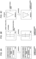
- Figs. 3A to 3C show display examples of the overspeed display mode.
- the display device 200 displays according to a difference (V - Vs) between the current vehicle speed V and the safe traveling vehicle speed Vs.
- the driver can check an overspeed degree of the current vehicle speed V relative to the safe traveling vehicle speed Vs.
- the current vehicle speed V, the safe traveling vehicle speed Vs, and the difference (V - Vs) are respectively indicated on the HUD by numerical values.
- the current vehicle speed V is indicated by a height of a bar graph
- the safe traveling vehicle speed V S is indicated by a height position of the bar graph in the HUD.
- an inverted triangular part is displayed on the windshield
- the current vehicle speed V is indicated by a height thereof
- the difference (V - V S ) is indicated by a width thereof.
- a driver who desires to constantly check the overspeed degree of the current vehicle speed V relative to the safe traveling vehicle speed V S can select the overspeed display mode by performing a predetermined operation.
- the overspeed non-display mode is a display mode in which the display device 200 does not display according to the difference between the current vehicle speed V and the reference vehicle speed.
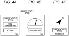
- Figs. 4A to 4C show display examples of the overspeed non-display mode.
- the display device 200 displays predetermined information without displaying according to the difference (V - Vs) between the current vehicle speed V and the safe traveling vehicle speed Vs. Accordingly, the driver can check information different from the overspeed degree of the current vehicle speed V relative to the safe traveling vehicle speed Vs.
- the current vehicle speed V, fuel consumption, and a voltage are indicated by numerical values on the HUD.
- Fig. 4A the current vehicle speed V, fuel consumption, and a voltage are indicated by numerical values on the HUD.
- the current vehicle speed V is indicated by a digitally displayed speed meter, and a travel distance is indicated by a numerical value on the HUD.
- north is indicated by an arrow mark, and the current vehicle speed V is indicated by a numerical value on the windshield.
- a driver who desires to check the predetermined information (voltage, fuel consumption, travel distance, travel direction, and the like in the examples of Figs. 4A to 4C ) without constantly checking the overspeed degree of the current vehicle speed V relative to the safe traveling vehicle speed Vs can select the overspeed non-display mode by performing a predetermined operation. In the overspeed non-display mode, a display function itself may be assumed to be disabled.
- the display control unit 103 controls the display device 200 to forcibly displays the overspeed display mode. That is, when determining the current vehicle speed V to be in the overspeed state, the display control unit 103 switches to display the overspeed display mode even when the overspeed non-display mode was selected.
- the display control unit 103 in this way functions as a display control unit of the present invention.
- Fig. 2 is a flowchart of a process performed by the display controller 100 according to the present embodiment.
- the flowchart of Fig. 2 is periodically repeated.
- the second determination unit 102 performs the lateral overspeed determination. Specifically, the second determination unit 102 determines whether the current vehicle speed V is in the overspeed state relative to the allowable lateral vehicle speed V L .
- a condition of the overspeed state is that the current vehicle speed V is equal to or higher than vehicle speed obtained by subtracting a predetermined vehicle speed value from the allowable lateral vehicle speed V L .
- the process proceeds to step S3.
- no overspeed state is determined, the process proceeds to step S2.
- step S2 the first determination unit 101 performs the longitudinal overspeed determination. Specifically, the first determination unit 101 determines whether the current vehicle speed V is in the overspeed state relative to the road legal speed V LS during traveling.
- a condition of the overspeed state is that the current vehicle speed V is equal to or higher than vehicle speed obtained by adding a predetermined vehicle speed value to the legal speed V LS .
- a condition of the overspeed state may further be that time during which the current vehicle speed V is equal to or higher than the legal speed V LS is equal to or longer than predetermined time. These conditions may be adopted, and the overspeed state may be determined when any one of the conditions is satisfied.
- the process proceeds to step S3. When no overspeed state is determined, the process exits the flowchart.
- step S3 the display control unit 103 controls the display device 200 to forcibly display the overspeed display mode on an assumption that the current vehicle speed V is determined to be in the overspeed state. That is, even when the overspeed non-display mode was selected, the display control unit 103 switches to display the overspeed display mode. Specifically, when the overspeed display mode is being displayed as shown in Figs. 3A to 3C , the overspeed display mode is continued. When the overspeed non-display mode is being displayed as shown in Figs. 4A to 4C , the overspeed non-display mode is switched to the overspeed display mode as shown in Figs. 3A to 3C . In the overspeed display mode performed in step S3, as shown in Figs. 3A to 3C , a difference display part, the bar graph, the inverted triangular part and the like are illuminated, blinked, or highlighted to notify the driver that the current vehicle speed V is in the overspeed state.
- the longitudinal determination criterion is a determination criterion according to the difference between the current vehicle speed V and the legal speed V LS
- the lateral determination criterion is a determination criterion according to the difference between the current vehicle speed V and the allowable lateral vehicle speed V L .
- step S1 priority is given to the lateral overspeed determination in step S1 over the longitudinal overspeed determination in step S2.
- the overspeed display mode is forcibly displayed in step S3.
- a condition of the overspeed state is that the current vehicle speed V is equal to or higher than vehicle speed obtained by subtracting a predetermined vehicle speed value from the allowable lateral vehicle speed V L .
- This condition can be said to be stricter than the condition in the longitudinal overspeed determination in step S2.
- the lateral overspeed may cause vehicle behaviors to be immediately unstable and the vehicle may easily deviate from the lane. In some cases, a high level of handling is required to shift to safe driving, and no cornering force may be obtained when deceleration by a brake pedal is fairly strong. In this way, since it is necessary to prevent overspeed in advance in the lateral direction, the overspeed display mode is forcibly displayed in advance.
- the longitudinal overspeed determination in step S2 at least one of a condition that the current vehicle speed V is equal to or higher than vehicle speed obtained by adding a predetermined vehicle speed value to the legal speed V LS and a condition that time during which the current vehicle speed V is equal to or higher than the legal speed V LS is equal to or longer than predetermined time is set as a condition of the overspeed state.
- This condition can be said to be gentler than the condition in the lateral overspeed determination in step S1.
- the longitudinal overspeed is less likely to cause vehicle behaviors to be significantly unstable immediately, and there is sufficient time for the driver to notice the overspeed and decelerate, and it can be said that the vehicle can easily shift to safe traveling by releasing an accelerator pedal or depressing the brake pedal. In this way, the forcible display of the overspeed display mode tends to be restrained in the longitudinal direction.
- Figs. 6A to 6D show the longitudinal overspeed determination and the lateral overspeed determination.
- Fig. 6A shows a state in which the vehicle is traveling on a straight expressway.
- the legal speed V LS 80 km/h, and the allowable lateral vehicle speed V L is 120 km/h.
- the overspeed state is determined in step S1 when the current vehicle speed V exceeds, for example, 100 km/h, and the overspeed state is unlikely to be determined in step S1.
- the overspeed state may be determined in step S2, and the safe traveling vehicle speed V S can be said to correspond to the legal speed V LS .
- Fig. 6C shows a state in which the vehicle is traveling on a general straight road.
- the legal speed V LS 60 km/h, and the allowable lateral vehicle speed V L is 120 km/h. Also in this case, the same situation as that shown in Fig. 6A can be said.
- Fig. 6B shows a state in which the vehicle is traveling on a general road curve (R40).
- the legal speed V LS is 60 km/h
- the allowable lateral vehicle speed V L is 33 km/h.
- the smaller the curvature radius the smaller the allowable lateral vehicle speed V L tends to be, and the allowable lateral vehicle speed V L may be smaller than the legal speed V LS .
- the overspeed state is determined in step S1 before being determined in step S2. Therefore, the safe traveling vehicle speed Vs can be said to correspond to the allowable lateral vehicle speed V L . Since a generated centrifugal force is larger as the curvature radius is smaller, the vehicle is more likely to run out of the lane. Therefore, when the allowable lateral vehicle speed V L is smaller than the legal speed V LS , the overspeed display mode according to the lateral overspeed determination is forcibly displayed.
- Fig. 6D shows a state in which the vehicle is traveling on a general road curve (R150).
- the legal speed V LS is 60 km/h
- the allowable lateral vehicle speed V L is 60 km/h.
- the overspeed state is determined in step S1 before being determined in step S2. Therefore, the safe traveling vehicle speed Vs can be said to correspond to the allowable lateral vehicle speed V L .
- the lateral overspeed determination is prioritized on a curve where the legal speed V LS is equal to the allowable lateral vehicle speed V L .
- the overspeed display mode and the overspeed non-display mode are selectable, unnecessary display can be restrained for a driver who does not need to constantly check the overspeed degree of the current vehicle speed V relative to the safe traveling vehicle speed Vs. Since the overspeed display mode is forcibly displayed when the current vehicle speed V is determined to be in the overspeed state, information on the difference between the current vehicle speed V and the safe traveling vehicle speed V S can be available in a situation where the information is useful.
- the overspeed state means not only a state in which the current vehicle speed V is actually equal to or higher than certain vehicle speed but also, for example, a state in which the current vehicle speed V is predicted to equal certain vehicle speed or higher.
- the allowable lateral vehicle speed V L is determined using the road curvature radius and the road surface friction coefficient ⁇ as parameters. Alternatively, other parameters (for example, crosswind speed, vehicle characteristics) may also be used. An upper limit value may be set for the allowable lateral vehicle speed V L so that the driver can set the overspeed display mode to be forcibly displayed in advance.
- the lateral overspeed determination may be applied only when the road on which the vehicle is currently traveling is predicted to come to a road having a small curvature radius on a one way road or at a T-shaped junction intersection, or when a road can be predicted by a car navigation system, and the overspeed determination may be performed by allocating the current vehicle speed V and the allowable lateral vehicle speed V L before the vehicle enters a curve.
- the display controller to which the present invention is applied is implemented by a computer device including a CPU, a ROM, a RAM, and the like, and functions of the respective units are implemented by executing, for example, a predetermined program stored in the ROM by the CPU.
- the display controller to which the present invention is applied may be implemented by a plurality of cooperating computer devices.
Landscapes
- Engineering & Computer Science (AREA)
- Chemical & Material Sciences (AREA)
- Combustion & Propulsion (AREA)
- Transportation (AREA)
- Mechanical Engineering (AREA)
- Traffic Control Systems (AREA)
- Control Of Driving Devices And Active Controlling Of Vehicle (AREA)
- Instrument Panels (AREA)
Abstract
A display controller (100) that controls a display device (200) mounted on a vehicle including a display control unit (103) configured to control the display device (200) to display as selectable an overspeed display mode in which the display device (200) displays according to a difference between current vehicle speed and reference vehicle speed and an overspeed non-display mode in which the display device (200) does not display according to the difference between the current vehicle speed and the reference vehicle speed and control the display device (200) to forcibly display the overspeed display mode when the current vehicle speed is determined to be in an overspeed state.
Description
- The present invention relates to a display controller that controls a display device mounted on a vehicle.
- In a vehicle such as an automatic vehicle, vehicle speed (referred to as "current vehicle speed" in the present application) measured by a vehicle speed sensor is generally displayed, and further information based on the current vehicle speed is displayed in certain vehicles. For example,
Patent Literature 1 discloses a speed sensation control device that calculates a size of an inverted triangle that is visual information based on traveling speed and displays the inverted triangle having the calculated size on a windshield. - Patent Literature 1:
JP5256075B - When the information based on the current vehicle speed is constantly displayed, a driver who does not need to constantly check the information based on the current vehicle speed may feel bothered since unnecessary information enters a field of view. Therefore, a configuration is conceivable in which the driver can select not to display the information based on the current vehicle speed. However, when the information based on the current vehicle speed is selected not to be displayed, the information based on the current vehicle speed would be not used even in a situation where the information is useful, and effects thereof cannot be exhibited.
- The present invention is made in view of such circumstances, and an object of the present invention is to make it possible to select not to display information based on current vehicle speed and to make the information based on the current vehicle speed available in a situation where the information is useful.
- According to an aspect of the present invention, there is provided a display controller that controls a display device mounted on a vehicle including a display control unit configured to control the display device to display as selectable an overspeed display mode in which the display device displays according to difference between current vehicle speed and reference vehicle speed and an overspeed non-display mode in which the display device does not display according to the difference between the current vehicle speed and the reference vehicle speed, and control the display device to forcibly display the overspeed display mode when the current vehicle speed is determined to be in an overspeed state.
- According to the present invention, it is possible to select not to display information based on current vehicle speed and to make the information based on the current vehicle speed available in a situation where the information is useful.
-
-
Fig. 1 shows a configuration of a display system of a vehicle according to an embodiment; -
Fig. 2 is a flowchart of a process performed by a display controller according to the embodiment; -
Figs. 3A to 3C show a display example of an overspeed display mode; -
Figs. 4A to 4C show a display example of an overspeed non-display mode; -
Fig. 5 shows an example of an allowable lateral vehicle speed associated with a road curvature radius and a road surface friction coefficient µ; and -
Figs. 6A to 6D show longitudinal overspeed determination and lateral overspeed determination. - According to an aspect of the present invention, there is provided a display controller (100) that controls a display device (200) mounted on a vehicle including a display control unit (103) configured to control the display device (200) to display as selectable an overspeed display mode in which the display device (200) displays according to a difference between current vehicle speed (V) and reference vehicle speed (Vs) and an overspeed non-display mode in which the display device (200) displays according to the difference between the current vehicle speed (V) and the reference vehicle speed (Vs), and control the display device (200) to forcibly display the overspeed display mode when the current vehicle speed (V) is determined to be in an overspeed state. Accordingly, it is possible to select not to display information on the difference between the current vehicle speed (V) and the reference vehicle speed (Vs), and to make the information on the difference between the current vehicle speed (V) and the reference vehicle speed (VS) available in a situation where the information is useful.
- Hereinafter, a preferred embodiment of the present invention will be described with reference to the accompanying drawings. In the present application, a traveling direction of a vehicle is referred to as a longitudinal direction, and a left-right direction relative to the traveling direction is referred to as a lateral direction.
-
Fig. 1 shows a configuration of a display system of a vehicle according to an embodiment. Adisplay device 200 is mounted around a periphery of a driver seat of the vehicle. Thedisplay device 200 is, for example, an electronic device that displays information on a windshield, a head up display (HUD), a meter panel, or the like. - A
display controller 100 controls thedisplay device 200 mounted on the automatic vehicle. Thedisplay controller 100 includes afirst determination unit 101, asecond determination unit 102, and adisplay control unit 103. - The
display controller 100 receives vehicle speed (current vehicle speed) measured by avehicle speed sensor 300. Thedisplay controller 100 further receives car navigation information acquired by acar navigation system 400. The car navigation information includes road legal speed VLS during traveling and a road curvature radius during traveling. Although the road legal speed VLS during traveling and the road curvature radius during traveling are acquired from thecar navigation system 400, the road legal speed VLS during traveling and the road curvature radius during traveling may be acquired by another unit such as an in-vehicle camera. Thedisplay controller 100 further receives information on a road surface condition estimated by a roadsurface estimation unit 500. The information on the road surface condition includes a road surface friction coefficient µ. The roadsurface estimation unit 500 may adopt a known technique and a description thereof is omitted here. - The
first determination unit 101 performs overspeed determination according to a determination criterion in the longitudinal direction (hereinafter referred to as longitudinal overspeed determination), and determines whether current vehicle speed V is in an overspeed state relative to the road legal speed VLS during traveling. As described above, the road legal speed VLS during traveling can be acquired from thecar navigation system 400. - The
second determination unit 102 performs overspeed determination according to a determination criterion in the lateral direction (hereinafter referred to as lateral overspeed determination), and determines whether the current vehicle speed V is in the overspeed state relative to allowable lateral vehicle speed VL. The allowable lateral vehicle speed VL is a maximum speed at which the vehicle can travel on a road curve without running out of a lane. For example, the allowable lateral vehicle speed VL is stored in advance in association with the road curvature radius and the road surface friction coefficient µ.Fig. 5 shows an example of the allowable lateral vehicle speed VL associated with the road curvature radius and the road surface friction coefficient µ. The allowable lateral vehicle speed VL = Va to Vi is determined in a manner of being divided by large, medium, and small curvature radii and large, medium, and small road surface friction coefficients µ. The allowable lateral vehicle speed VL tends to decrease as the curvature radius decreases (becomes a sharp curve), and the allowable lateral vehicle speed VL tends to decrease as the road surface friction coefficient µ decreases (becomes slippery). As described above, the road curvature radius during traveling can be acquired from thecar navigation system 400, the road surface friction coefficient µ can be acquired from the roadsurface estimation unit 500, and thus the allowable lateral vehicle speed VL can be determined. - The
display control unit 103 controls thedisplay device 200 to display as selectable an overspeed display mode and an overspeed non-display mode selectable. When contents displayed in the overspeed display mode and contents displayed in the overspeed non-display mode are all displayed, it is necessary for thedisplay device 200 to be capable of displaying a large amount of information at a once, and more information than necessary may be provided to the driver. Since the overspeed display mode and the overspeed non-display mode are selectable, it is not necessary for thedisplay device 200 to display a large amount of information at a once, and only necessary information can be provided to the driver. - The overspeed display mode is a display mode in which the
display device 200 displays according to a difference between the current vehicle speed V and reference vehicle speed. The reference vehicle speed is vehicle speed determined from a viewpoint of safe traveling and stable traveling, and is hereinafter referred to as safe traveling vehicle speed Vs. As will be described later, the safe traveling vehicle speed Vs corresponds to one of the road legal speed VLS during traveling and the allowable lateral vehicle speed VL. InFigs. 3A to 3C show display examples of the overspeed display mode. In the overspeed display mode, thedisplay device 200 displays according to a difference (V - Vs) between the current vehicle speed V and the safe traveling vehicle speed Vs. Accordingly, the driver can check an overspeed degree of the current vehicle speed V relative to the safe traveling vehicle speed Vs. In the example ofFig. 3A , the current vehicle speed V, the safe traveling vehicle speed Vs, and the difference (V - Vs) are respectively indicated on the HUD by numerical values. In the example ofFig. 3B , the current vehicle speed V is indicated by a height of a bar graph, and the safe traveling vehicle speed VS is indicated by a height position of the bar graph in the HUD. In the example ofFig. 3C , an inverted triangular part is displayed on the windshield, the current vehicle speed V is indicated by a height thereof, and the difference (V - VS) is indicated by a width thereof. A driver who desires to constantly check the overspeed degree of the current vehicle speed V relative to the safe traveling vehicle speed VS can select the overspeed display mode by performing a predetermined operation. - The overspeed non-display mode is a display mode in which the
display device 200 does not display according to the difference between the current vehicle speed V and the reference vehicle speed. InFigs. 4A to 4C show display examples of the overspeed non-display mode. In the overspeed non-display mode, thedisplay device 200 displays predetermined information without displaying according to the difference (V - Vs) between the current vehicle speed V and the safe traveling vehicle speed Vs. Accordingly, the driver can check information different from the overspeed degree of the current vehicle speed V relative to the safe traveling vehicle speed Vs. In the example ofFig. 4A , the current vehicle speed V, fuel consumption, and a voltage are indicated by numerical values on the HUD. In the example ofFig. 4B , the current vehicle speed V is indicated by a digitally displayed speed meter, and a travel distance is indicated by a numerical value on the HUD. In the example ofFig. 4C , north is indicated by an arrow mark, and the current vehicle speed V is indicated by a numerical value on the windshield. A driver who desires to check the predetermined information (voltage, fuel consumption, travel distance, travel direction, and the like in the examples ofFigs. 4A to 4C ) without constantly checking the overspeed degree of the current vehicle speed V relative to the safe traveling vehicle speed Vs can select the overspeed non-display mode by performing a predetermined operation. In the overspeed non-display mode, a display function itself may be assumed to be disabled. - When receiving the determination by the
first determination unit 101 and the determination by thesecond determination unit 102 and determining the current vehicle speed V to be in the overspeed state, thedisplay control unit 103 controls thedisplay device 200 to forcibly displays the overspeed display mode. That is, when determining the current vehicle speed V to be in the overspeed state, thedisplay control unit 103 switches to display the overspeed display mode even when the overspeed non-display mode was selected. Thedisplay control unit 103 in this way functions as a display control unit of the present invention. -
Fig. 2 is a flowchart of a process performed by thedisplay controller 100 according to the present embodiment. The flowchart ofFig. 2 is periodically repeated. In step S1, thesecond determination unit 102 performs the lateral overspeed determination. Specifically, thesecond determination unit 102 determines whether the current vehicle speed V is in the overspeed state relative to the allowable lateral vehicle speed VL. In the present embodiment, a condition of the overspeed state is that the current vehicle speed V is equal to or higher than vehicle speed obtained by subtracting a predetermined vehicle speed value from the allowable lateral vehicle speed VL. When the overspeed state is determined, the process proceeds to step S3. When no overspeed state is determined, the process proceeds to step S2. - In step S2, the
first determination unit 101 performs the longitudinal overspeed determination. Specifically, thefirst determination unit 101 determines whether the current vehicle speed V is in the overspeed state relative to the road legal speed VLS during traveling. In the present embodiment, a condition of the overspeed state is that the current vehicle speed V is equal to or higher than vehicle speed obtained by adding a predetermined vehicle speed value to the legal speed VLS. A condition of the overspeed state may further be that time during which the current vehicle speed V is equal to or higher than the legal speed VLS is equal to or longer than predetermined time. These conditions may be adopted, and the overspeed state may be determined when any one of the conditions is satisfied. When the overspeed state is determined, the process proceeds to step S3. When no overspeed state is determined, the process exits the flowchart. - In step S3, the
display control unit 103 controls thedisplay device 200 to forcibly display the overspeed display mode on an assumption that the current vehicle speed V is determined to be in the overspeed state. That is, even when the overspeed non-display mode was selected, thedisplay control unit 103 switches to display the overspeed display mode. Specifically, when the overspeed display mode is being displayed as shown inFigs. 3A to 3C , the overspeed display mode is continued. When the overspeed non-display mode is being displayed as shown inFigs. 4A to 4C , the overspeed non-display mode is switched to the overspeed display mode as shown inFigs. 3A to 3C . In the overspeed display mode performed in step S3, as shown inFigs. 3A to 3C , a difference display part, the bar graph, the inverted triangular part and the like are illuminated, blinked, or highlighted to notify the driver that the current vehicle speed V is in the overspeed state. - As the determination criteria for determining whether the current vehicle speed V is in the overspeed state described above, two determination criteria including a longitudinal determination criterion in the longitudinal overspeed determination and a lateral determination criterion in the lateral overspeed determination are prepared. The longitudinal determination criterion is a determination criterion according to the difference between the current vehicle speed V and the legal speed VLS, and the lateral determination criterion is a determination criterion according to the difference between the current vehicle speed V and the allowable lateral vehicle speed VL. When the overspeed state is determined in the lateral overspeed determination in step S1, the overspeed display mode is forcibly displayed in step S3. In this way, priority is given to the lateral overspeed determination in step S1 over the longitudinal overspeed determination in step S2. When no overspeed state is determined in the lateral overspeed determination in step S1 and the overspeed state is determined in the longitudinal overspeed determination in step S2, the overspeed display mode is forcibly displayed in step S3.
- In the lateral overspeed determination in step S1, a condition of the overspeed state is that the current vehicle speed V is equal to or higher than vehicle speed obtained by subtracting a predetermined vehicle speed value from the allowable lateral vehicle speed VL. This condition can be said to be stricter than the condition in the longitudinal overspeed determination in step S2. The lateral overspeed may cause vehicle behaviors to be immediately unstable and the vehicle may easily deviate from the lane. In some cases, a high level of handling is required to shift to safe driving, and no cornering force may be obtained when deceleration by a brake pedal is fairly strong. In this way, since it is necessary to prevent overspeed in advance in the lateral direction, the overspeed display mode is forcibly displayed in advance.
- In contrast, in the longitudinal overspeed determination in step S2, at least one of a condition that the current vehicle speed V is equal to or higher than vehicle speed obtained by adding a predetermined vehicle speed value to the legal speed VLS and a condition that time during which the current vehicle speed V is equal to or higher than the legal speed VLS is equal to or longer than predetermined time is set as a condition of the overspeed state. This condition can be said to be gentler than the condition in the lateral overspeed determination in step S1. The longitudinal overspeed is less likely to cause vehicle behaviors to be significantly unstable immediately, and there is sufficient time for the driver to notice the overspeed and decelerate, and it can be said that the vehicle can easily shift to safe traveling by releasing an accelerator pedal or depressing the brake pedal. In this way, the forcible display of the overspeed display mode tends to be restrained in the longitudinal direction.
- Specific examples of the longitudinal overspeed determination and the lateral overspeed determination will be described with reference to
Figs. 6A to 6D. Figs. 6A to 6D show the longitudinal overspeed determination and the lateral overspeed determination.Fig. 6A shows a state in which the vehicle is traveling on a straight expressway. Thelegal speed V LS 80 km/h, and the allowable lateral vehicle speed VL is 120 km/h. In this case, the overspeed state is determined in step S1 when the current vehicle speed V exceeds, for example, 100 km/h, and the overspeed state is unlikely to be determined in step S1. Further, the overspeed state may be determined in step S2, and the safe traveling vehicle speed VS can be said to correspond to the legal speed VLS. When traveling on a straight road having a large curvature radius, the vehicle is less likely to run out of the lane, and the allowable lateral vehicle speed VL is also large. Accordingly, the overspeed display mode according to the longitudinal overspeed determination is more likely to be forcibly displayed than that according to the lateral overspeed determination.Fig. 6C shows a state in which the vehicle is traveling on a general straight road. Thelegal speed V LS 60 km/h, and the allowable lateral vehicle speed VL is 120 km/h. Also in this case, the same situation as that shown inFig. 6A can be said. -
Fig. 6B shows a state in which the vehicle is traveling on a general road curve (R40). The legal speed VLS is 60 km/h, and the allowable lateral vehicle speed VL is 33 km/h. The smaller the curvature radius, the smaller the allowable lateral vehicle speed VL tends to be, and the allowable lateral vehicle speed VL may be smaller than the legal speed VLS. In this case, the overspeed state is determined in step S1 before being determined in step S2. Therefore, the safe traveling vehicle speed Vs can be said to correspond to the allowable lateral vehicle speed VL. Since a generated centrifugal force is larger as the curvature radius is smaller, the vehicle is more likely to run out of the lane. Therefore, when the allowable lateral vehicle speed VL is smaller than the legal speed VLS, the overspeed display mode according to the lateral overspeed determination is forcibly displayed. -
Fig. 6D shows a state in which the vehicle is traveling on a general road curve (R150). The legal speed VLS is 60 km/h, and the allowable lateral vehicle speed VL is 60 km/h. In this case, the overspeed state is determined in step S1 before being determined in step S2. Therefore, the safe traveling vehicle speed Vs can be said to correspond to the allowable lateral vehicle speed VL. In this way, the lateral overspeed determination is prioritized on a curve where the legal speed VLS is equal to the allowable lateral vehicle speed VL. - As described with reference to
Figs. 6B to 6D , on the general straight road and the general road curve that have the same legal speed VLS, forcible display of the overspeed display mode by the longitudinal overspeed determination tends to be restrained on the straight road, whereas forcible display of the overspeed display mode by the lateral overspeed determination is performed in advance on the curve where vehicle behaviors are more likely to be unstable. - As described above, since the overspeed display mode and the overspeed non-display mode are selectable, unnecessary display can be restrained for a driver who does not need to constantly check the overspeed degree of the current vehicle speed V relative to the safe traveling vehicle speed Vs. Since the overspeed display mode is forcibly displayed when the current vehicle speed V is determined to be in the overspeed state, information on the difference between the current vehicle speed V and the safe traveling vehicle speed VS can be available in a situation where the information is useful.
- In the present application, the overspeed state means not only a state in which the current vehicle speed V is actually equal to or higher than certain vehicle speed but also, for example, a state in which the current vehicle speed V is predicted to equal certain vehicle speed or higher.
- In the present embodiment, the allowable lateral vehicle speed VL is determined using the road curvature radius and the road surface friction coefficient µ as parameters. Alternatively, other parameters (for example, crosswind speed, vehicle characteristics) may also be used. An upper limit value may be set for the allowable lateral vehicle speed VL so that the driver can set the overspeed display mode to be forcibly displayed in advance.
- Further, the lateral overspeed determination may be applied only when the road on which the vehicle is currently traveling is predicted to come to a road having a small curvature radius on a one way road or at a T-shaped junction intersection, or when a road can be predicted by a car navigation system, and the overspeed determination may be performed by allocating the current vehicle speed V and the allowable lateral vehicle speed VL before the vehicle enters a curve.
- Although the embodiment of the present invention is described in detail with reference to the drawings, the embodiment is merely a specific example for carrying out the present invention. The technical scope of the present invention is not limited to the example. Various modifications are possible without departing from the spirit of the present invention, and the modifications are also included in the technical scope of the present invention. The display controller to which the present invention is applied is implemented by a computer device including a CPU, a ROM, a RAM, and the like, and functions of the respective units are implemented by executing, for example, a predetermined program stored in the ROM by the CPU. The display controller to which the present invention is applied may be implemented by a plurality of cooperating computer devices.
-
- 100: display controller
- 101: first determination unit
- 102: second determination unit
- 103: display control unit
- 200: display device
- 300: vehicle speed sensor
- 400: car navigation system
- 500: road surface estimation unit
Claims (5)
- A display controller (100) that controls a display device (200) mounted on a vehicle, the display controller (100) comprising:
a display control unit (103) configured to:control the display device (200) to display as selectable an overspeed display mode in which the display device (200) displays according to a difference between current vehicle speed and reference vehicle speed and an overspeed non-display mode in which the display device (200) does not displays according to the difference between the current vehicle speed and the reference vehicle speed; andcontrol the display device (200) to forcibly display the overspeed display mode when the current vehicle speed is determined to be in an overspeed state. - The display controller (100) according to claim 1, further comprising:a first determination unit (101) configured to determine whether the current vehicle speed is in the overspeed state relative to road legal speed during traveling; anda second determination unit (102) configured to determine whether the current vehicle speed is in the overspeed state relative to allowable lateral vehicle speed that is a maximum speed at which the vehicle can travel on a road curve without running out of a lane, whereinthe display control unit (103) controls the display device (200) to forcibly display the overspeed display mode when the current vehicle speed is determined to be in the overspeed state by the second determination unit (102), andthe display control unit (103) controls the display device (200) to forcibly display the overspeed display mode when the current vehicle speed is determined not to be in the overspeed state by the second determination unit (102) and the current vehicle speed is determined to be in the overspeed state is determined by the first determination unit (101).
- The display controller (100) according to claim 2, wherein the first determination unit (101) determines that the current vehicle speed is in the overspeed state based on at least one of a condition that the current vehicle speed is equal to or faster than vehicle speed obtained by adding a predetermined vehicle speed value to the legal speed and a condition that time during which the current vehicle speed is equal to or faster than the legal speed is equal to or longer than predetermined time.
- The display controller (100) according to claim 2 or 3, wherein the second determination unit (102) determines that the current vehicle speed is in the overspeed state based on a condition that the current vehicle speed is equal to or greater than vehicle speed obtained by subtracting a predetermined vehicle speed value from the allowable lateral vehicle speed.
- The display controller (100) according to claim 1 or 2, whereinthe overspeed display mode is a display mode that a driver can check an overspeed degree of the current vehicle speed relative to the reference vehicle speed, andthe overspeed non-display mode is a display mode that the driver can check information different from the overspeed degree of the current vehicle speed relative to the reference vehicle speed.
Applications Claiming Priority (1)
| Application Number | Priority Date | Filing Date | Title |
|---|---|---|---|
| JP2022097339A JP2023183691A (en) | 2022-06-16 | 2022-06-16 | display control device |
Publications (1)
| Publication Number | Publication Date |
|---|---|
| EP4292857A1 true EP4292857A1 (en) | 2023-12-20 |
Family
ID=86604892
Family Applications (1)
| Application Number | Title | Priority Date | Filing Date |
|---|---|---|---|
| EP23175548.9A Pending EP4292857A1 (en) | 2022-06-16 | 2023-05-26 | Display controller |
Country Status (2)
| Country | Link |
|---|---|
| EP (1) | EP4292857A1 (en) |
| JP (1) | JP2023183691A (en) |
Citations (9)
| Publication number | Priority date | Publication date | Assignee | Title |
|---|---|---|---|---|
| JP2005148973A (en) * | 2003-11-13 | 2005-06-09 | Nissan Motor Co Ltd | Information presentation device |
| EP1544637A2 (en) * | 2000-01-26 | 2005-06-22 | Origin Technologies Limited | Speed trap detection and warning system |
| JP5256075B2 (en) | 2009-02-23 | 2013-08-07 | スタンレー電気株式会社 | Speed sensor |
| EP3297886A2 (en) * | 2015-05-20 | 2018-03-28 | Compagnie Générale des Etablissements Michelin | Method for determing a limit speed for driving |
| US20190210522A1 (en) * | 2018-01-11 | 2019-07-11 | Mindtronic Ai Co.,Ltd. | Warning system implemented in a vehicle and method thereof |
| DE112019001919T5 (en) * | 2018-04-10 | 2021-01-21 | Bendix Commercial Vehicle Systems Llc | DEVICE AND PROCEDURE FOR IDENTIFYING AN OVER SPEEDING CONDITION OF A VEHICLE |
| CN112950974A (en) * | 2021-04-12 | 2021-06-11 | 东风柳州汽车有限公司 | Vehicle speed limit prompting method, device, equipment and storage medium |
| US20210370831A1 (en) * | 2020-06-02 | 2021-12-02 | Mando Corporation | Apparatus for assisting driving, vehicle having the same, and method of controlling the same |
| CN114463985A (en) * | 2022-03-04 | 2022-05-10 | 北京百度网讯科技有限公司 | Driving assistance method, device, equipment and storage medium |
Family Cites Families (6)
| Publication number | Priority date | Publication date | Assignee | Title |
|---|---|---|---|---|
| JP4209951B2 (en) * | 1995-08-07 | 2009-01-14 | 日産自動車株式会社 | Automotive display device |
| JP5472003B2 (en) * | 2010-09-20 | 2014-04-16 | 株式会社デンソー | Speed display device for vehicle |
| JP5904137B2 (en) * | 2013-02-12 | 2016-04-13 | 株式会社デンソー | Vehicle display device |
| KR101491330B1 (en) * | 2013-10-17 | 2015-02-06 | 현대자동차주식회사 | Apparatus and Method for Display of Cluster |
| JP2019127065A (en) * | 2018-01-22 | 2019-08-01 | 日本精機株式会社 | Display control device, and head-up display device |
| JP7253708B2 (en) * | 2020-03-17 | 2023-04-07 | パナソニックIpマネジメント株式会社 | Information processing device, vehicle, and information processing method |
-
2022
- 2022-06-16 JP JP2022097339A patent/JP2023183691A/en active Pending
-
2023
- 2023-05-26 EP EP23175548.9A patent/EP4292857A1/en active Pending
Patent Citations (9)
| Publication number | Priority date | Publication date | Assignee | Title |
|---|---|---|---|---|
| EP1544637A2 (en) * | 2000-01-26 | 2005-06-22 | Origin Technologies Limited | Speed trap detection and warning system |
| JP2005148973A (en) * | 2003-11-13 | 2005-06-09 | Nissan Motor Co Ltd | Information presentation device |
| JP5256075B2 (en) | 2009-02-23 | 2013-08-07 | スタンレー電気株式会社 | Speed sensor |
| EP3297886A2 (en) * | 2015-05-20 | 2018-03-28 | Compagnie Générale des Etablissements Michelin | Method for determing a limit speed for driving |
| US20190210522A1 (en) * | 2018-01-11 | 2019-07-11 | Mindtronic Ai Co.,Ltd. | Warning system implemented in a vehicle and method thereof |
| DE112019001919T5 (en) * | 2018-04-10 | 2021-01-21 | Bendix Commercial Vehicle Systems Llc | DEVICE AND PROCEDURE FOR IDENTIFYING AN OVER SPEEDING CONDITION OF A VEHICLE |
| US20210370831A1 (en) * | 2020-06-02 | 2021-12-02 | Mando Corporation | Apparatus for assisting driving, vehicle having the same, and method of controlling the same |
| CN112950974A (en) * | 2021-04-12 | 2021-06-11 | 东风柳州汽车有限公司 | Vehicle speed limit prompting method, device, equipment and storage medium |
| CN114463985A (en) * | 2022-03-04 | 2022-05-10 | 北京百度网讯科技有限公司 | Driving assistance method, device, equipment and storage medium |
Also Published As
| Publication number | Publication date |
|---|---|
| JP2023183691A (en) | 2023-12-28 |
Similar Documents
| Publication | Publication Date | Title |
|---|---|---|
| CN110466532B (en) | Method of providing driver performance feedback to a vehicle driver and related system | |
| EP2537727B1 (en) | Method for estimating a speed profile for a vehicle | |
| CN110481546B (en) | Information display device for vehicle | |
| CN104736409B (en) | Method and system for promoting uniform driving style | |
| CN102632888B (en) | A method and a warning device for warning a vehicle driver, and a vehicle | |
| US9409554B2 (en) | Method for improving the driving stability | |
| CN104002811B (en) | For the method running the driver assistance system of the motor vehicles side of the vertical and horizontal guiding function with combination | |
| EP2022694A1 (en) | System and method for controlling running of a vehicle | |
| WO2021005645A1 (en) | Control system for vehicle, control method for vehicle, and program | |
| EP1241064B1 (en) | Braking/driving control apparatus and method for automotive vehicle | |
| US20110307152A1 (en) | Vehicle travel control device | |
| KR20070068430A (en) | Process for enhancing the safety and/or comfort of a motor vehicle | |
| US20250346116A1 (en) | Vehicle display control device, vehicle display system, vehicle display control method, and non-transitory storage medium | |
| CN105818686A (en) | Intelligent driving control method and system for vehicle | |
| EP4177126B1 (en) | Driver controlling system for a vehicle | |
| JP4924903B2 (en) | Vehicle display device | |
| JP6198386B2 (en) | Driving assistance device | |
| EP3145766B1 (en) | Method and system for the adaptation of the driving of a vehicle on a roadway in association with taking a curve | |
| JP6990221B2 (en) | Vehicle and its control device and control method | |
| CN113968228A (en) | Method for providing support for driver of vehicle when driving through front curve | |
| JP2023183691A (en) | display control device | |
| CN116080677B (en) | Driver control system for vehicle | |
| JP2005181277A (en) | Speed display device | |
| CN114771523B (en) | Vehicle control device, method of operation of vehicle control device and storage medium | |
| EP4491476A1 (en) | Method for inducing the use of a speed control system of a vehicle, data processing apparatus, computer program, computer-readable storage medium, speed control system, and vehicle |
Legal Events
| Date | Code | Title | Description |
|---|---|---|---|
| PUAI | Public reference made under article 153(3) epc to a published international application that has entered the european phase |
Free format text: ORIGINAL CODE: 0009012 |
|
| STAA | Information on the status of an ep patent application or granted ep patent |
Free format text: STATUS: REQUEST FOR EXAMINATION WAS MADE |
|
| 17P | Request for examination filed |
Effective date: 20230624 |
|
| AK | Designated contracting states |
Kind code of ref document: A1 Designated state(s): AL AT BE BG CH CY CZ DE DK EE ES FI FR GB GR HR HU IE IS IT LI LT LU LV MC ME MK MT NL NO PL PT RO RS SE SI SK SM TR |