EP4292746A1 - Welding apparatus for cylindrical battery cell - Google Patents
Welding apparatus for cylindrical battery cell Download PDFInfo
- Publication number
- EP4292746A1 EP4292746A1 EP22820503.5A EP22820503A EP4292746A1 EP 4292746 A1 EP4292746 A1 EP 4292746A1 EP 22820503 A EP22820503 A EP 22820503A EP 4292746 A1 EP4292746 A1 EP 4292746A1
- Authority
- EP
- European Patent Office
- Prior art keywords
- rod
- welding
- exterior cover
- welding device
- center rod
- Prior art date
- Legal status (The legal status is an assumption and is not a legal conclusion. Google has not performed a legal analysis and makes no representation as to the accuracy of the status listed.)
- Granted
Links
Images


Classifications
-
- B—PERFORMING OPERATIONS; TRANSPORTING
- B23—MACHINE TOOLS; METAL-WORKING NOT OTHERWISE PROVIDED FOR
- B23K—SOLDERING OR UNSOLDERING; WELDING; CLADDING OR PLATING BY SOLDERING OR WELDING; CUTTING BY APPLYING HEAT LOCALLY, e.g. FLAME CUTTING; WORKING BY LASER BEAM
- B23K11/00—Resistance welding; Severing by resistance heating
- B23K11/36—Auxiliary equipment
-
- B—PERFORMING OPERATIONS; TRANSPORTING
- B23—MACHINE TOOLS; METAL-WORKING NOT OTHERWISE PROVIDED FOR
- B23K—SOLDERING OR UNSOLDERING; WELDING; CLADDING OR PLATING BY SOLDERING OR WELDING; CUTTING BY APPLYING HEAT LOCALLY, e.g. FLAME CUTTING; WORKING BY LASER BEAM
- B23K11/00—Resistance welding; Severing by resistance heating
- B23K11/002—Resistance welding; Severing by resistance heating specially adapted for particular articles or work
-
- B—PERFORMING OPERATIONS; TRANSPORTING
- B23—MACHINE TOOLS; METAL-WORKING NOT OTHERWISE PROVIDED FOR
- B23K—SOLDERING OR UNSOLDERING; WELDING; CLADDING OR PLATING BY SOLDERING OR WELDING; CUTTING BY APPLYING HEAT LOCALLY, e.g. FLAME CUTTING; WORKING BY LASER BEAM
- B23K11/00—Resistance welding; Severing by resistance heating
- B23K11/30—Features relating to electrodes
-
- B—PERFORMING OPERATIONS; TRANSPORTING
- B23—MACHINE TOOLS; METAL-WORKING NOT OTHERWISE PROVIDED FOR
- B23K—SOLDERING OR UNSOLDERING; WELDING; CLADDING OR PLATING BY SOLDERING OR WELDING; CUTTING BY APPLYING HEAT LOCALLY, e.g. FLAME CUTTING; WORKING BY LASER BEAM
- B23K11/00—Resistance welding; Severing by resistance heating
- B23K11/30—Features relating to electrodes
- B23K11/31—Electrode holders and actuating devices therefor
- B23K11/318—Supporting devices for electrode holders
-
- H—ELECTRICITY
- H01—ELECTRIC ELEMENTS
- H01M—PROCESSES OR MEANS, e.g. BATTERIES, FOR THE DIRECT CONVERSION OF CHEMICAL ENERGY INTO ELECTRICAL ENERGY
- H01M10/00—Secondary cells; Manufacture thereof
- H01M10/04—Construction or manufacture in general
-
- H—ELECTRICITY
- H01—ELECTRIC ELEMENTS
- H01M—PROCESSES OR MEANS, e.g. BATTERIES, FOR THE DIRECT CONVERSION OF CHEMICAL ENERGY INTO ELECTRICAL ENERGY
- H01M10/00—Secondary cells; Manufacture thereof
- H01M10/04—Construction or manufacture in general
- H01M10/0431—Cells with wound or folded electrodes
-
- H—ELECTRICITY
- H01—ELECTRIC ELEMENTS
- H01M—PROCESSES OR MEANS, e.g. BATTERIES, FOR THE DIRECT CONVERSION OF CHEMICAL ENERGY INTO ELECTRICAL ENERGY
- H01M10/00—Secondary cells; Manufacture thereof
- H01M10/05—Accumulators with non-aqueous electrolyte
- H01M10/058—Construction or manufacture
- H01M10/0587—Construction or manufacture of accumulators having only wound construction elements, i.e. wound positive electrodes, wound negative electrodes and wound separators
-
- H—ELECTRICITY
- H01—ELECTRIC ELEMENTS
- H01M—PROCESSES OR MEANS, e.g. BATTERIES, FOR THE DIRECT CONVERSION OF CHEMICAL ENERGY INTO ELECTRICAL ENERGY
- H01M50/00—Constructional details or processes of manufacture of the non-active parts of electrochemical cells other than fuel cells, e.g. hybrid cells
- H01M50/50—Current conducting connections for cells or batteries
- H01M50/528—Fixed electrical connections, i.e. not intended for disconnection
-
- H—ELECTRICITY
- H01—ELECTRIC ELEMENTS
- H01M—PROCESSES OR MEANS, e.g. BATTERIES, FOR THE DIRECT CONVERSION OF CHEMICAL ENERGY INTO ELECTRICAL ENERGY
- H01M50/00—Constructional details or processes of manufacture of the non-active parts of electrochemical cells other than fuel cells, e.g. hybrid cells
- H01M50/50—Current conducting connections for cells or batteries
- H01M50/531—Electrode connections inside a battery casing
-
- H—ELECTRICITY
- H01—ELECTRIC ELEMENTS
- H01M—PROCESSES OR MEANS, e.g. BATTERIES, FOR THE DIRECT CONVERSION OF CHEMICAL ENERGY INTO ELECTRICAL ENERGY
- H01M50/00—Constructional details or processes of manufacture of the non-active parts of electrochemical cells other than fuel cells, e.g. hybrid cells
- H01M50/50—Current conducting connections for cells or batteries
- H01M50/531—Electrode connections inside a battery casing
- H01M50/536—Electrode connections inside a battery casing characterised by the method of fixing the leads to the electrodes, e.g. by welding
-
- B—PERFORMING OPERATIONS; TRANSPORTING
- B23—MACHINE TOOLS; METAL-WORKING NOT OTHERWISE PROVIDED FOR
- B23K—SOLDERING OR UNSOLDERING; WELDING; CLADDING OR PLATING BY SOLDERING OR WELDING; CUTTING BY APPLYING HEAT LOCALLY, e.g. FLAME CUTTING; WORKING BY LASER BEAM
- B23K2101/00—Articles made by soldering, welding or cutting
- B23K2101/36—Electric or electronic devices
-
- B—PERFORMING OPERATIONS; TRANSPORTING
- B23—MACHINE TOOLS; METAL-WORKING NOT OTHERWISE PROVIDED FOR
- B23K—SOLDERING OR UNSOLDERING; WELDING; CLADDING OR PLATING BY SOLDERING OR WELDING; CUTTING BY APPLYING HEAT LOCALLY, e.g. FLAME CUTTING; WORKING BY LASER BEAM
- B23K2101/00—Articles made by soldering, welding or cutting
- B23K2101/36—Electric or electronic devices
- B23K2101/38—Conductors
-
- Y—GENERAL TAGGING OF NEW TECHNOLOGICAL DEVELOPMENTS; GENERAL TAGGING OF CROSS-SECTIONAL TECHNOLOGIES SPANNING OVER SEVERAL SECTIONS OF THE IPC; TECHNICAL SUBJECTS COVERED BY FORMER USPC CROSS-REFERENCE ART COLLECTIONS [XRACs] AND DIGESTS
- Y02—TECHNOLOGIES OR APPLICATIONS FOR MITIGATION OR ADAPTATION AGAINST CLIMATE CHANGE
- Y02E—REDUCTION OF GREENHOUSE GAS [GHG] EMISSIONS, RELATED TO ENERGY GENERATION, TRANSMISSION OR DISTRIBUTION
- Y02E60/00—Enabling technologies; Technologies with a potential or indirect contribution to GHG emissions mitigation
- Y02E60/10—Energy storage using batteries
Definitions
- the present disclosure relates to a welding device for a cylindrical battery cell.
- Secondary batteries that have ease of application according to product groups and have electrical characteristics such as high energy density are universally applied not only to portable devices, but also to electric vehicles (EVs) or hybrid electric vehicles (HEVs) driven by an electric drive source. These secondary batteries are attracting attention as a new energy source for improving eco-friendliness and energy efficiency because they not only have the primary advantage of dramatically reducing the use of fossil fuels, but also do not generate any by-products from the use of energy.
- EVs electric vehicles
- HEVs hybrid electric vehicles
- Types of secondary batteries currently widely used include lithium-ion batteries, lithium polymer batteries, nickel cadmium batteries, nickel hydrogen batteries, nickel zinc batteries, and the like.
- a unit secondary battery cell that is, a unit battery cell, has an operating voltage of about 2.5 V to 4.5 V. Therefore, when a higher output voltage is required, a battery pack may be configured by connecting a plurality of battery cells in series. In addition, a plurality of battery cells may be connected in parallel to form a battery pack according to the charge/discharge capacity required for the battery pack. Accordingly, the number of battery cells included in the battery pack may be variously set according to a required output voltage and/or charge/discharge capacity.
- the cylindrical battery cell is manufactured in such a way that a jelly-roll type electrode assembly is accommodated in a battery can together with an electrolyte.
- a negative electrode tab protruding downward from the jelly-roll type electrode assembly is coupled to an electric connection component such as a current collecting plate or a lead tab by welding, and then is accommodated in the battery can. Then, the bottom surface of the battery can and the electric connection component are joined by welding.
- a resistance welding method is mainly employed, and during this welding process, damage to the electrode assembly or the separator may occur.
- damage to the electrode assembly or the separator may occur due to friction between the welding rod and the electrode assembly while the welding rod is inserted into a winding center hole provided at the winding center of the jelly-roll type electrode assembly.
- the risk of damage to the electrode assembly or the separator is higher when the high-temperature welding rod is taken out.
- the present disclosure is designed to solve the problems of the related art, and therefore the present disclosure is directed to minimizing damage to an electrode assembly and/or a separator, when performing welding for bonding a bottom surface of a battery can and an electric connection component connected to an electrode tab of the electrode assembly such as a current collecting plate or a lead tab.
- the present disclosure is directed to providing a welding device capable of expanding a winding center hole of an electrode assembly, thereby preventing a direct contact between a high-temperature welding portion and an electrode assembly, thereby preventing friction between the high-temperature welding part portion and the electrode assembly, resulting in minimizing the occurrence of defects in the electrode assembly.
- a welding device which includes a welding rod configured to be inserted into a winding center hole provided at a winding center of an electrode assembly inserted into a battery can to weld an electrode tab of the electrode assembly or an electric connection component coupled with the electrode tab to a bottom surface of the battery can, wherein the welding rod includes: a center rod located at a center of the welding rod in a diameter direction; and an exterior cover configured to cover an outer circumference of the center rod and installed to be movable in a first direction away from the center rod and in a second direction closer to the center rod.
- the plurality of unit covers may be configured to increase an outer diameter of the welding rod by moving along the first direction.
- the plurality of unit covers may be configured such that adjacent unit covers partially overlap each other according to an operating state.
- At least one of the center rod and the exterior cover may be configured to be movable along an extension direction of the center rod such that one of both longitudinal ends of the center rod, which is inserted toward the bottom surface of the battery can, is exposed to the outside of the exterior cover or covered by the exterior cover.
- the welding device may further comprise a support body configured to support the welding rod.
- the support body may include at least one control unit configured to control movement of the welding rod.
- the support body may have an insert hole into which the welding rod is inserted, and at least one of the center rod and the exterior cover may be configured to be movable along the extension direction of the center rod inside the insert hole.
- the support body may include at least one control unit configured to control movement of at least one of the center rod and the exterior cover.
- the welding device of the present disclosure it is possible to expand the winding center hole of the jelly-roll type electrode assembly. Therefore, direct contact between the high-temperature welding portion and the electrode assembly may be prevented. In addition, by preventing friction between the high-temperature welding portion and the electrode assembly, it is possible to minimize the occurrence of defects in the electrode assembly.
- the present disclosure may have various other effects, which will be described in each embodiment, or a corresponding description will be omitted for effects that can be easily inferred by a person skilled in the art.
- FIG. 1 is a diagram for explaining a welding device according to an embodiment of the present disclosure
- FIG. 2 is a diagram for explaining a welding rod of the welding device of FIG. 1 .
- a welding device 1 includes a welding rod 10.
- the welding device 1 may further include a support body 20.
- the welding device 1 is configured to be inserted into a winding center hole C provided at a winding center of an electrode assembly 110 inserted into a battery can 130 of a cylindrical battery cell 100 to weld an electrode tab (not shown) provided in the electrode assembly 110 or an electric connection component 120 coupled with the electrode tab to a bottom surface of the battery can 130.
- the welding rod 10 includes a center rod 11 positioned at the center of the welding rod 10 in the diameter direction and an exterior cover 12 that covers the outer circumference of the center rod 11.
- a length of the welding rod 10 in the longitudinal direction may be greater than or equal to a length of the electrode assembly 110 in the height direction.
- the length of the welding rod 10 in the longitudinal direction is greater than the length of the electrode assembly 110 in the height direction, which is accommodated in the battery can 130. Accordingly, an end of the welding rod 10 may contact the electric connection component 120 coupled to the electrode tab (not shown) of the electrode assembly 110. Accordingly, the electric connection component 120 and the bottom surface of the battery can 130 may be easily welded.
- the center rod 11 is located approximately at the center of the welding rod 10 in the diameter direction.
- the center rod 11 may have a shape in which its diameter is longer than its length. That is, the center rod 11 may have an approximately cylindrical shape that is thin and long.
- the center rod 11 may have an approximately needle shape with a relatively small diameter compared to its length.
- a first direction and a second direction may be defined.
- the center rod 11 may be assumed to be an approximately cylinder whose central axis is parallel to the length direction of the center rod 11.
- a +r direction may be defined as the first direction
- a -r direction may be defined as the second direction. That is, the first direction may be a direction away from the central axis of the center rod 11, and the second direction may be a direction closer to the central axis of the center rod 11.
- At least one of the center rod 11 and the exterior cover 12 may be configured to be movable along the extension direction of the center rod 11 such that one of both longitudinal ends of the center rod 11, which is inserted toward the inner bottom surface of the battery can 130, is exposed to the outside of the exterior cover 12 or covered by the exterior cover 12.
- the end of the welding rod 10 may be retracted to the inside of the exterior cover 12, and only when welding is performed, the end of the welding rod 10 may be exposed to the outside of the exterior cover 12.
- the position of the welding rod 10 is fixed and the exterior cover 12 moves along the length direction of the welding rod 10 so that the end of the welding rod 10 is exposed to the outside of the exterior cover 12 or covered by the exterior cover 12.
- the end of the welding rod 10 is exposed to the outside of the exterior cover 12 or completely covered by the exterior cover 12 by moving both the welding rod 10 and the exterior cover 12.
- the thermal conductivity of the exterior cover 12 may be equal to or lower than the thermal conductivity of the center rod 11.
- the material of the exterior cover 12 may be the same as the material of the center rod 11. Since the center rod 11 performs resistance welding, it is generally made of metal. At this time, the material of the exterior cover 12 may also be metal. In this case, the rigidity of exterior cover 12 may be secured to a certain level. Therefore, the exterior cover 12 may easily increase the diameter of the winding center hole C.
- the thermal conductivity of the exterior cover 12 may be lower than the thermal conductivity of the center rod 11. According to the configuration of the present disclosure, it is possible to minimize the transfer of heat from the center rod 11 heated to a high temperature for welding to the electrode assembly 110, thereby preventing damage to the electrode assembly 110.
- a separator may be disposed on the inner wall of the winding center hole C of the electrode assembly 110, and in this case, damage to the separator may be prevented by lowering the thermal conductivity of the exterior cover 12.
- the material of the exterior cover 12 may be a high-strength plastic material with excellent rigidity and low thermal conductivity.
- the high-strength plastic may contain, for example, glass fibers in order to withstand a significant increase in the temperature of the center rod 11.
- a material of the exterior cover 12 in addition, for example, a ceramic material may be applied.
- the exterior cover 12 may serve as a thermal shield between the center rod 11 and the electrode assembly 110, thereby preventing thermal damage to the electrode assembly 110.
- the material of the exterior cover 12 is not limited thereto, and various materials having high rigidity even in a thin thickness may be applied to the exterior cover 12.
- FIG. 4 is a diagram for explaining an exterior cover of the welding rod of FIG. 2, and FIGS. 3 and 5 are diagrams for explaining exterior covers according to other embodiment of the present disclosure.
- the exterior cover 12 may include a plurality of unit covers 13 that cover a part of the outer circumference of the center rod 11 and are arranged along a perimeter of the outer circumference.
- the plurality of unit covers 13 may be configured to increase the outer diameter of the welding rod 10 by moving along the first direction.
- the distance between the plurality of unit covers 13 may be changed.
- the plurality of unit covers 13 may be configured such that a distance between adjacent unit covers 13 increases according to the movement in the first direction, and a distance between adjacent unit covers 13 decreases according to the movement in the second direction.
- the plurality of unit covers 13 may be configured to surround the center rod 11 without being spaced apart from each other so that the center rod 11 is not exposed to the outside of the exterior cover 12, before the exterior cover 12 is expanded.
- the unit covers 13 move in the first direction for the expansion of the exterior cover 12, the distance between the unit covers 13 may increase.
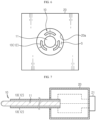
- FIG. 6 is a diagram of FIG. 2 , viewed in an A direction
- FIG. 7 is a diagram for explaining a support body 20 of the welding device 1 of FIG. 1 .
- the plurality of unit covers 13 may move along the first direction or the second direction within a space formed between the inner wall of the insert hole 20a and the center rod 11.
- the support body 20 may have an insert hole 20a in which the welding rod 10 and the exterior cover 12 may be accommodated, and at this time, a space S may be formed between the center rod 11 and the inner wall of the insert hole 20a.
- each of the plurality of unit covers 13 may have a structure that moves in the first direction or the second direction by an actuator (not shown) electronically controlled by the control unit 21.
- a motor may be provided inside the support body 20, and the motor and the control unit 21 may be electrically connected. At this time, by operating the motor through the control unit 21, the unit cover 13 connected to the motor may move in the first direction or the second direction. Therefore, the diameter of the welding rod 10 may be increased or decreased.
- the control unit 21 may move the center rod 11 and/or the exterior cover 12 along a direction parallel to the central axis of the welding rod 10. That is, the support body 20 may include at least one control unit configured to control the operation of at least one of the center rod 11 and the exterior cover 12. At least one of the center rod 11 and the exterior cover 12 may be mechanically connected to the control unit 21 and configured to operate in a direction parallel to the extension direction of the center rod 11 according to the motion of the control unit 21. Alternatively, at least one of the center rod 11 and the exterior cover 12 may be configured to operate in a direction parallel to the extension direction of the center rod 11 by an actuator (not shown) electronically controlled by the control unit 21.
- control unit 21 for controlling the movement for exposing and hiding the center rod 11 and the control unit 21 for controlling the change of the outer diameter of the welding rod 10 may be the same control unit, or may be different control units provided separately.
Landscapes
- Engineering & Computer Science (AREA)
- Chemical & Material Sciences (AREA)
- Chemical Kinetics & Catalysis (AREA)
- Electrochemistry (AREA)
- General Chemical & Material Sciences (AREA)
- Mechanical Engineering (AREA)
- Manufacturing & Machinery (AREA)
- Connection Of Batteries Or Terminals (AREA)
- Sealing Battery Cases Or Jackets (AREA)
- Resistance Welding (AREA)
Abstract
Description
- The present application claims priority to
Korean Patent Application No. 10-2021-0075731 filed on June 10, 2021 Korean Patent Application No. 10-2022-0063978 filed on May 25, 2022 - The present disclosure relates to a welding device for a cylindrical battery cell.
- Secondary batteries that have ease of application according to product groups and have electrical characteristics such as high energy density are universally applied not only to portable devices, but also to electric vehicles (EVs) or hybrid electric vehicles (HEVs) driven by an electric drive source. These secondary batteries are attracting attention as a new energy source for improving eco-friendliness and energy efficiency because they not only have the primary advantage of dramatically reducing the use of fossil fuels, but also do not generate any by-products from the use of energy.
- Types of secondary batteries currently widely used include lithium-ion batteries, lithium polymer batteries, nickel cadmium batteries, nickel hydrogen batteries, nickel zinc batteries, and the like. Such a unit secondary battery cell, that is, a unit battery cell, has an operating voltage of about 2.5 V to 4.5 V. Therefore, when a higher output voltage is required, a battery pack may be configured by connecting a plurality of battery cells in series. In addition, a plurality of battery cells may be connected in parallel to form a battery pack according to the charge/discharge capacity required for the battery pack. Accordingly, the number of battery cells included in the battery pack may be variously set according to a required output voltage and/or charge/discharge capacity.
- On the other hand, the cylindrical battery cell is manufactured in such a way that a jelly-roll type electrode assembly is accommodated in a battery can together with an electrolyte. At this time, a negative electrode tab protruding downward from the jelly-roll type electrode assembly is coupled to an electric connection component such as a current collecting plate or a lead tab by welding, and then is accommodated in the battery can. Then, the bottom surface of the battery can and the electric connection component are joined by welding.
- On the other hand, as such a welding method, a resistance welding method is mainly employed, and during this welding process, damage to the electrode assembly or the separator may occur. For example, damage to the electrode assembly or the separator may occur due to friction between the welding rod and the electrode assembly while the welding rod is inserted into a winding center hole provided at the winding center of the jelly-roll type electrode assembly. In addition, since the temperature of the welding rod is very elevated after welding, the risk of damage to the electrode assembly or the separator is higher when the high-temperature welding rod is taken out.
- Therefore, it is required to find a way to minimize damage to the jelly-roll type electrode assembly or the separator when welding the electric connection component and the bottom surface of the battery can.
- The present disclosure is designed to solve the problems of the related art, and therefore the present disclosure is directed to minimizing damage to an electrode assembly and/or a separator, when performing welding for bonding a bottom surface of a battery can and an electric connection component connected to an electrode tab of the electrode assembly such as a current collecting plate or a lead tab.
- In particular, the present disclosure is directed to providing a welding device capable of expanding a winding center hole of an electrode assembly, thereby preventing a direct contact between a high-temperature welding portion and an electrode assembly, thereby preventing friction between the high-temperature welding part portion and the electrode assembly, resulting in minimizing the occurrence of defects in the electrode assembly.
- However, the technical object to be solved by the present disclosure is not limited to the above, and other objects not mentioned herein will be clearly understood by those skilled in the art from the following disclosure.
- In one aspect of the present disclosure, there is provided a welding device, which includes a welding rod configured to be inserted into a winding center hole provided at a winding center of an electrode assembly inserted into a battery can to weld an electrode tab of the electrode assembly or an electric connection component coupled with the electrode tab to a bottom surface of the battery can, wherein the welding rod includes: a center rod located at a center of the welding rod in a diameter direction; and an exterior cover configured to cover an outer circumference of the center rod and installed to be movable in a first direction away from the center rod and in a second direction closer to the center rod.
- As the exterior cover moves in the first direction, the exterior cover may be configured to press an inner wall of the winding center hole to increase a diameter of the winding center hole.
- The center rod may have a shape in which a diameter thereof is longer than a length thereof.
- The first direction and the second direction may be directions parallel to a radial direction of the center rod.
- The exterior cover may include a plurality of unit covers configured to cover a part of the outer circumference of the center rod and arranged along a perimeter of the outer circumference.
- The plurality of unit covers may be configured to increase an outer diameter of the welding rod by moving along the first direction.
- The plurality of unit covers may be configured such that a distance between adjacent unit covers increases according to the movement in the first direction and the distance between adjacent unit covers decreases according to the movement in the second direction.
- The plurality of unit covers may be configured such that adjacent unit covers partially overlap each other according to an operating state.
- A length of the welding rod in a longitudinal direction may be greater than or equal to a length of the electrode assembly in a height direction.
- A minimum outer diameter of the welding rod according to an operating state of the exterior cover may be equal to or smaller than a diameter of the winding center hole of the electrode assembly.
- Thermal conductivity of the exterior cover may be lower than thermal conductivity of the center rod.
- One of both longitudinal ends of the center rod, which is inserted toward the bottom surface of the battery can, may be exposed to the outside of the exterior cover.
- At least one of the center rod and the exterior cover may be configured to be movable along an extension direction of the center rod such that one of both longitudinal ends of the center rod, which is inserted toward the bottom surface of the battery can, is exposed to the outside of the exterior cover or covered by the exterior cover.
- The welding device may further comprise a support body configured to support the welding rod.
- The support body may have an insert hole into which the welding rod is inserted, and the plurality of unit covers may be configured to move along the first direction and the second direction within a space formed between an inner wall of the insert hole and the center rod.
- The support body may include at least one control unit configured to control movement of the welding rod.
- Each of the plurality of unit covers may be configured to be mechanically connected to the control unit to move in the first direction and the second direction according to motion of the control unit.
- Each of the plurality of unit covers may be configured to move in the first direction and the second direction by an actuator electronically controlled by the control unit.
- The welding device may further comprise a support body configured to support the welding rod.
- The support body may have an insert hole into which the welding rod is inserted, and at least one of the center rod and the exterior cover may be configured to be movable along the extension direction of the center rod inside the insert hole.
- The support body may include at least one control unit configured to control movement of at least one of the center rod and the exterior cover.
- At least one of the center rod and the exterior cover may be configured to be mechanically connected to the control unit to move in a direction parallel to an extension direction of the center rod according to motion of the control unit.
- At least one of the center rod and the exterior cover may be configured to move in a direction parallel to an extension direction of the center rod by an actuator electronically controlled by the control unit.
- According to the present disclosure, in performing welding for bonding between an electric connection component such as a current collecting plate or a lead tab and the bottom surface of a battery can, damage to a jelly-roll type electrode assembly or a separator may be minimized.
- In particular, according to the welding device of the present disclosure, it is possible to expand the winding center hole of the jelly-roll type electrode assembly. Therefore, direct contact between the high-temperature welding portion and the electrode assembly may be prevented. In addition, by preventing friction between the high-temperature welding portion and the electrode assembly, it is possible to minimize the occurrence of defects in the electrode assembly.
- In addition, the present disclosure may have various other effects, which will be described in each embodiment, or a corresponding description will be omitted for effects that can be easily inferred by a person skilled in the art.
- The accompanying drawings illustrate a preferred embodiment of the present disclosure and together with the foregoing disclosure, serve to provide further understanding of the technical features of the present disclosure, and thus, the present disclosure is not construed as being limited to the drawing.
-
FIG. 1 is a diagram for explaining a welding device according to an embodiment of the present disclosure. -
FIG. 2 is a diagram for explaining a welding rod of the welding device ofFIG. 1 . -
FIG. 3 is a diagram for explaining an exterior cover according to another embodiment of the present disclosure. -
FIG. 4 is a diagram for explaining an exterior cover of the welding rod ofFIG. 2 . -
FIG. 5 is a diagram for explaining an exterior cover according to another embodiment of the present disclosure. -
FIG. 6 is a diagram ofFIG. 2 , viewed in an A direction. -
FIG. 7 is a diagram for explaining a support body of the welding device ofFIG. 1 . - Hereinafter, preferred embodiments of the present disclosure will be described in detail with reference to the accompanying drawings. Prior to the description, it should be understood that the terms used in the specification and the appended claims should not be construed as limited to general and dictionary meanings, but interpreted based on the meanings and concepts corresponding to technical aspects of the present disclosure on the basis of the principle that the inventor is allowed to define terms appropriately for the best explanation.
- Therefore, the description proposed herein is just a preferable example for the purpose of illustrations only, not intended to limit the scope of the disclosure, so it should be understood that other equivalents and modifications could be made thereto without departing from the scope of the disclosure.
- In addition, in order to help understanding of the present disclosure, the accompanying drawings are not drawn to scale, but dimensions of some components may be exaggerated.
-
FIG. 1 is a diagram for explaining a welding device according to an embodiment of the present disclosure, andFIG. 2 is a diagram for explaining a welding rod of the welding device ofFIG. 1 . - Referring to
FIGS. 1 and2 , awelding device 1 according to an embodiment of the present disclosure includes awelding rod 10. Thewelding device 1 may further include asupport body 20. - The
welding device 1 is configured to be inserted into a winding center hole C provided at a winding center of anelectrode assembly 110 inserted into a battery can 130 of acylindrical battery cell 100 to weld an electrode tab (not shown) provided in theelectrode assembly 110 or anelectric connection component 120 coupled with the electrode tab to a bottom surface of the battery can 130. - The
electrode assembly 110 may be, for example, a jelly-roll type electrode assembly. Theelectric connection component 120 means, for example, a component for electrically connecting theelectrode assembly 110 and the battery can 130, like an electrode current collecting plate or a lead tab coupled to an electrode tab (not shown) protruding downward from theelectrode assembly 110. In the drawings of the present disclosure, theelectric connection component 120 is illustrated as an electrode current collecting plate as an example. Meanwhile, the welding method may be, for example, a resistance welding method. - Referring to
FIGS. 1 and2 , thewelding rod 10 includes acenter rod 11 positioned at the center of thewelding rod 10 in the diameter direction and anexterior cover 12 that covers the outer circumference of thecenter rod 11. - A length of the
welding rod 10 in the longitudinal direction may be greater than or equal to a length of theelectrode assembly 110 in the height direction. For example, referring toFIG. 1 , the length of thewelding rod 10 in the longitudinal direction is greater than the length of theelectrode assembly 110 in the height direction, which is accommodated in the battery can 130. Accordingly, an end of thewelding rod 10 may contact theelectric connection component 120 coupled to the electrode tab (not shown) of theelectrode assembly 110. Accordingly, theelectric connection component 120 and the bottom surface of the battery can 130 may be easily welded. - Referring to
FIGS. 1 and2 , thecenter rod 11 is located approximately at the center of thewelding rod 10 in the diameter direction. Thecenter rod 11 may have a shape in which its diameter is longer than its length. That is, thecenter rod 11 may have an approximately cylindrical shape that is thin and long. For example, referring toFIG. 1 , thecenter rod 11 may have an approximately needle shape with a relatively small diameter compared to its length. - As a direction parallel to the radial direction of the
center rod 11, a first direction and a second direction may be defined. For example, referring toFIG. 2 , thecenter rod 11 may be assumed to be an approximately cylinder whose central axis is parallel to the length direction of thecenter rod 11. At this time, in the radial directions of the cylinder, a +r direction may be defined as the first direction, and a -r direction may be defined as the second direction. That is, the first direction may be a direction away from the central axis of thecenter rod 11, and the second direction may be a direction closer to the central axis of thecenter rod 11. - Referring to
FIG. 2 , one of both longitudinal ends of thecenter rod 11, which is inserted toward the inner bottom surface of the battery can 130, may be exposed to the outside of theexterior cover 12. If the end of thecenter rod 11 is not exposed to the outside of theexterior cover 12, it may not be easy for thecenter rod 11 to contact theelectric connection component 120. Therefore, the end of thecenter rod 11 may be exposed to the outside of theexterior cover 12 for easy welding. However, the end of thecenter rod 11 is not limited to always being exposed to the outside of theexterior cover 12. That is, at least one of thecenter rod 11 and theexterior cover 12 may be configured to be movable along the extension direction of thecenter rod 11 such that one of both longitudinal ends of thecenter rod 11, which is inserted toward the inner bottom surface of the battery can 130, is exposed to the outside of theexterior cover 12 or covered by theexterior cover 12. - For example, before welding, the end of the
welding rod 10 may be retracted to the inside of theexterior cover 12, and only when welding is performed, the end of thewelding rod 10 may be exposed to the outside of theexterior cover 12. Also, on the contrary, it is also possible that the position of thewelding rod 10 is fixed and theexterior cover 12 moves along the length direction of thewelding rod 10 so that the end of thewelding rod 10 is exposed to the outside of theexterior cover 12 or covered by theexterior cover 12. In addition, it is also possible that the end of thewelding rod 10 is exposed to the outside of theexterior cover 12 or completely covered by theexterior cover 12 by moving both thewelding rod 10 and theexterior cover 12. - Referring to
FIGS. 1 and2 , theexterior cover 12 covers the outer circumference of thecenter rod 11 and may be installed to be movable in the first direction away from thecenter rod 11 and in the second direction closer to thecenter rod 11. As moving in the first direction, theexterior cover 12 may be configured to press an inner wall of the winding center hole C to increase the diameter of the winding center hole C. Accordingly, a predetermined gap may be secured between theelectrode assembly 110 and thecenter rod 11. In consideration of this function, the minimum outer diameter of thewelding rod 10 according to the operating state of theexterior cover 12 may be formed to be equal to or smaller than the diameter of the winding center hole C of theelectrode assembly 110. - The thermal conductivity of the
exterior cover 12 may be equal to or lower than the thermal conductivity of thecenter rod 11. For example, the material of theexterior cover 12 may be the same as the material of thecenter rod 11. Since thecenter rod 11 performs resistance welding, it is generally made of metal. At this time, the material of theexterior cover 12 may also be metal. In this case, the rigidity ofexterior cover 12 may be secured to a certain level. Therefore, theexterior cover 12 may easily increase the diameter of the winding center hole C. - On the other hand, the thermal conductivity of the
exterior cover 12 may be lower than the thermal conductivity of thecenter rod 11. According to the configuration of the present disclosure, it is possible to minimize the transfer of heat from thecenter rod 11 heated to a high temperature for welding to theelectrode assembly 110, thereby preventing damage to theelectrode assembly 110. In particular, a separator may be disposed on the inner wall of the winding center hole C of theelectrode assembly 110, and in this case, damage to the separator may be prevented by lowering the thermal conductivity of theexterior cover 12. For example, the material of theexterior cover 12 may be a high-strength plastic material with excellent rigidity and low thermal conductivity. In this case, the high-strength plastic may contain, for example, glass fibers in order to withstand a significant increase in the temperature of thecenter rod 11. As a material of theexterior cover 12, in addition, for example, a ceramic material may be applied. When a material having lower thermal conductivity than thecenter rod 11 is applied as the material of theexterior cover 12, the heat of the hightemperature center rod 11 is not well conducted to theexterior cover 12. Accordingly, theexterior cover 12 may serve as a thermal shield between thecenter rod 11 and theelectrode assembly 110, thereby preventing thermal damage to theelectrode assembly 110. - However, the material of the
exterior cover 12 is not limited thereto, and various materials having high rigidity even in a thin thickness may be applied to theexterior cover 12. -
FIG. 4 is a diagram for explaining an exterior cover of the welding rod ofFIG. 2, and FIGS. 3 and5 are diagrams for explaining exterior covers according to other embodiment of the present disclosure. - Referring to
FIGS. 3 to 5 , theexterior cover 12 may include a plurality of unit covers 13 that cover a part of the outer circumference of thecenter rod 11 and are arranged along a perimeter of the outer circumference. In this case, the plurality of unit covers 13 may be configured to increase the outer diameter of thewelding rod 10 by moving along the first direction. - For example, the
exterior cover 12 includes two unit covers 13 inFIG. 3 , theexterior cover 12 includes three unit covers 13 inFIG. 4 , and theexterior cover 12 includes four unit covers 13 inFIG. 5 . As theexterior cover 12 includes a greater number of unit covers 13, the shape of the expanding winding center hole C may be closer to a circular shape. For example, inFIG. 3 , sinceexterior cover 12 includes twounit cover 13, theunit cover 13 has a structure that opens to both sides. Therefore, at this time, the shape of the winding center hole C becomes an approximately elliptical shape. On the other hand, inFIG. 5 , since theexterior cover 12 includes four unit covers 13, the unit covers 13 have a structure that opens in 4 directions at intervals of 90 degrees. Therefore, the shape of the winding center hole C at this time becomes approximately circular. - Referring to
FIGS. 3 to 5 , when theexterior cover 12 extends along the first direction, the distance between the plurality of unit covers 13 may be changed. For example, the plurality of unit covers 13 may be configured such that a distance between adjacent unit covers 13 increases according to the movement in the first direction, and a distance between adjacent unit covers 13 decreases according to the movement in the second direction. The plurality of unit covers 13 may be configured to surround thecenter rod 11 without being spaced apart from each other so that thecenter rod 11 is not exposed to the outside of theexterior cover 12, before theexterior cover 12 is expanded. However, when the unit covers 13 move in the first direction for the expansion of theexterior cover 12, the distance between the unit covers 13 may increase. Meanwhile, although not specifically illustrated in the drawings, the plurality of unit covers 13 may be configured such that adjacent unit covers 13 partially overlap each other according to an operating state. In this case, the overlapping area of the unit covers 13 adjacent to each other may be formed to be widest in a state before theexterior cover 12 is expanded. Conversely, in a state where theexterior cover 12 is expanded to the maximum, the overlapping area of adjacent unit covers 13 may be minimized, or the adjacent unit covers 13 may be spaced apart from each other not to generate an overlapping area. -
FIG. 6 is a diagram ofFIG. 2 , viewed in an A direction, andFIG. 7 is a diagram for explaining asupport body 20 of thewelding device 1 ofFIG. 1 . - Referring to
FIGS. 6 and 7 , thesupport body 20 may be configured to support thewelding rod 10. For example, thesupport body 20 may be coupled to thewelding rod 10 at one longitudinal side of thewelding rod 10. Thesupport body 20 may include aninsert hole 20a. - The plurality of unit covers 13 may move along the first direction or the second direction within a space formed between the inner wall of the
insert hole 20a and thecenter rod 11. For example, referring toFIGS. 6 and 7 , thesupport body 20 may have aninsert hole 20a in which thewelding rod 10 and theexterior cover 12 may be accommodated, and at this time, a space S may be formed between thecenter rod 11 and the inner wall of theinsert hole 20a. - Referring to
FIG. 7 , thesupport body 20 may include at least onecontrol unit 21. Thecontrol unit 21 may be configured to control movement of thewelding rod 10. For example, thecontrol unit 21 may be a mechanical control unit or an electronic control unit. - Specifically, for example, each of the plurality of unit covers 13 may be configured to be mechanically connected to the
control unit 21 to move in the first direction and the second direction according to motion of thecontrol unit 21. More specifically, for example, an arm to which a plurality of hinges are coupled may be connected to each of the plurality of unit covers 13, and thecontrol unit 21 may be a button or dial connected to the plurality of arms and configured to control movement of the plurality of arms. However, in the present disclosure, the mechanical connection structure for controlling the movement of the plurality of unit covers 13 through thecontrol unit 21 is not limited thereto, and any mechanical connection structure capable of increasing and decreasing the outer diameter of thewelding rod 10 by controlling the motion of the plurality of unit covers 13 may be applicable to the present disclosure. - Alternatively, each of the plurality of unit covers 13 may have a structure that moves in the first direction or the second direction by an actuator (not shown) electronically controlled by the
control unit 21. For example, a motor may be provided inside thesupport body 20, and the motor and thecontrol unit 21 may be electrically connected. At this time, by operating the motor through thecontrol unit 21, theunit cover 13 connected to the motor may move in the first direction or the second direction. Therefore, the diameter of thewelding rod 10 may be increased or decreased. - Meanwhile, the
control unit 21 may move thecenter rod 11 and/or theexterior cover 12 along a direction parallel to the central axis of thewelding rod 10. That is, thesupport body 20 may include at least one control unit configured to control the operation of at least one of thecenter rod 11 and theexterior cover 12. At least one of thecenter rod 11 and theexterior cover 12 may be mechanically connected to thecontrol unit 21 and configured to operate in a direction parallel to the extension direction of thecenter rod 11 according to the motion of thecontrol unit 21. Alternatively, at least one of thecenter rod 11 and theexterior cover 12 may be configured to operate in a direction parallel to the extension direction of thecenter rod 11 by an actuator (not shown) electronically controlled by thecontrol unit 21. - For example, when the
welding rod 10 is inserted into the winding center hole C of theelectrode assembly 110 or withdrawn from the winding center hole C, thecontrol unit 21 may be manipulated to move thecenter rod 11 toward thesupport body 20 or to move theexterior cover 12 away from thesupport body 20 so that the longitudinal end of thesupport body 20 is not exposed to the outside of theexterior cover 12, thereby preventing contact between thecenter rod 11 and theelectrode assembly 110. Of course, it is also possible to move thecenter rod 11 toward thesupport body 20 and to move theexterior cover 12 away from thesupport body 20 by manipulating thecontrol unit 21. - In addition, when performing welding, the
control unit 21 may be manipulated to move thecenter rod 11 away from thesupport body 20 or to move theexterior cover 12 toward thesupport body 20 so that the longitudinal end of thesupport body 20 is exposed to the outside of theexterior cover 12, thereby allowing thecenter rod 11 and theelectric connection component 120 to easily contact each other. Of course, it is also possible to move thecenter rod 11 away from thesupport body 20 and to move theexterior cover 12 toward thesupport body 20 by manipulating thecontrol unit 21. - In the present disclosure, the
control unit 21 for controlling the movement for exposing and hiding thecenter rod 11 and thecontrol unit 21 for controlling the change of the outer diameter of thewelding rod 10 may be the same control unit, or may be different control units provided separately. - On the other hand, although terms indicating directions such as up and down are used in this specification, these terms are only for convenience of explanation, and it is obvious to those skilled in the art of the present disclosure that they may vary depending on the location of a target object or the location of an observer.
- The present disclosure has been described in detail. However, it should be understood that the detailed description and specific examples, while indicating preferred embodiments of the disclosure, are given by way of illustration only, since various changes and modifications within the scope of the disclosure will become apparent to those skilled in the art from this detailed description.
-
- 1 welding device
- 10 welding rod
- 11 center rod
- 12 exterior cover
- 13 unit cover
- 20 support body
- 20a insert hole
- 21 control unit
- 100 cylindrical battery cell
- 110 electrode assembly
- 120 electric connection component
- 130 battery can
- C winding center hole
Claims (23)
- A welding device, which includes a welding rod configured to be inserted into a winding center hole provided at a winding center of an electrode assembly inserted into a battery can to weld an electrode tab of the electrode assembly or an electric connection component coupled with the electrode tab to a bottom surface of the battery can,
wherein the welding rod includes:a center rod located at a center of the welding rod in a diameter direction; andan exterior cover configured to cover an outer circumference of the center rod and installed to be movable in a first direction away from the center rod and in a second direction closer to the center rod. - The welding device according to claim 1,
wherein as the exterior cover moves in the first direction, the exterior cover is configured to press an inner wall of the winding center hole to increase a diameter of the winding center hole. - The welding device according to claim 1,
wherein the center rod has a shape in which a diameter thereof is longer than a length thereof. - The welding device according to claim 1,
wherein the first direction and the second direction are directions parallel to a radial direction of the center rod. - The welding device according to claim 1,
wherein the exterior cover includes a plurality of unit covers configured to cover a part of the outer circumference of the center rod and arranged along a perimeter of the outer circumference. - The welding device according to claim 5,
wherein the plurality of unit covers are configured to increase an outer diameter of the welding rod by moving along the first direction. - The welding device according to claim 6,
wherein the plurality of unit covers are configured such that a distance between adjacent unit covers increases according to the movement in the first direction and the distance between adjacent unit covers decreases according to the movement in the second direction. - The welding device according to claim 6,
wherein the plurality of unit covers are configured such that adjacent unit covers partially overlap each other according to an operating state. - The welding device according to claim 1,
wherein a length of the welding rod in a longitudinal direction is greater than or equal to a length of the electrode assembly in a height direction. - The welding device according to claim 1,
wherein a minimum outer diameter of the welding rod according to an operating state of the exterior cover is equal to or smaller than a diameter of the winding center hole of the electrode assembly. - The welding device according to claim 1,
wherein thermal conductivity of the exterior cover is lower than thermal conductivity of the center rod. - The welding device according to claim 1,
wherein one of both longitudinal ends of the center rod, which is inserted toward the bottom surface of the battery can, is exposed to the outside of the exterior cover. - The welding device according to claim 1,
wherein at least one of the center rod and the exterior cover is configured to be movable along an extension direction of the center rod such that one of both longitudinal ends of the center rod, which is inserted toward the bottom surface of the battery can, is exposed to the outside of the exterior cover or covered by the exterior cover. - The welding device according to claim 5, further comprising:
a support body configured to support the welding rod. - The welding device according to claim 14,wherein the support body has an insert hole into which the welding rod is inserted, andwherein the plurality of unit covers are configured to move along the first direction and the second direction within a space formed between an inner wall of the insert hole and the center rod.
- The welding device according to claim 14,
wherein the support body includes at least one control unit configured to control movement of the welding rod. - The welding device according to claim 16,
wherein each of the plurality of unit covers is configured to be mechanically connected to the control unit to move in the first direction and the second direction according to motion of the control unit. - The welding device according to claim 16,
wherein each of the plurality of unit covers is configured to move in the first direction and the second direction by an actuator electronically controlled by the control unit. - The welding device according to claim 13, further comprising:
a support body configured to support the welding rod. - The welding device according to claim 19,wherein the support body has an insert hole into which the welding rod is inserted, andwherein at least one of the center rod and the exterior cover is configured to be movable along the extension direction of the center rod inside the insert hole.
- The welding device according to claim 19,
wherein the support body includes at least one control unit configured to control movement of at least one of the center rod and the exterior cover. - The welding device according to claim 21,
wherein at least one of the center rod and the exterior cover is configured to be mechanically connected to the control unit to move in a direction parallel to an extension direction of the center rod according to motion of the control unit. - The welding device according to claim 21,
wherein at least one of the center rod and the exterior cover is configured to move in a direction parallel to an extension direction of the center rod by an actuator electronically controlled by the control unit.
Applications Claiming Priority (3)
| Application Number | Priority Date | Filing Date | Title |
|---|---|---|---|
| KR20210075731 | 2021-06-10 | ||
| KR1020220063978A KR20220166720A (en) | 2021-06-10 | 2022-05-25 | Welding device for Cylindrical battery cell |
| PCT/KR2022/007951 WO2022260375A1 (en) | 2021-06-10 | 2022-06-03 | Welding apparatus for cylindrical battery cell |
Publications (3)
| Publication Number | Publication Date |
|---|---|
| EP4292746A1 true EP4292746A1 (en) | 2023-12-20 |
| EP4292746A4 EP4292746A4 (en) | 2024-09-18 |
| EP4292746B1 EP4292746B1 (en) | 2025-11-05 |
Family
ID=84426208
Family Applications (1)
| Application Number | Title | Priority Date | Filing Date |
|---|---|---|---|
| EP22820503.5A Active EP4292746B1 (en) | 2021-06-10 | 2022-06-03 | Welding device for cylindrical battery cell |
Country Status (6)
| Country | Link |
|---|---|
| US (1) | US20240269762A1 (en) |
| EP (1) | EP4292746B1 (en) |
| JP (1) | JP7577226B2 (en) |
| ES (1) | ES3061557T3 (en) |
| PL (1) | PL4292746T3 (en) |
| WO (1) | WO2022260375A1 (en) |
Families Citing this family (1)
| Publication number | Priority date | Publication date | Assignee | Title |
|---|---|---|---|---|
| CN118648150A (en) * | 2022-07-27 | 2024-09-13 | 宁德时代新能源科技股份有限公司 | Needle assembly and winding device |
Family Cites Families (10)
| Publication number | Priority date | Publication date | Assignee | Title |
|---|---|---|---|---|
| JP5147882B2 (en) | 2010-03-18 | 2013-02-20 | 日立ビークルエナジー株式会社 | Secondary battery |
| KR20120138076A (en) * | 2011-06-14 | 2012-12-24 | 남궁선 | Welding torch equipped with protective cover |
| KR200472189Y1 (en) * | 2012-07-03 | 2014-04-17 | 현대중공업 주식회사 | Torch for arc welding |
| KR20150084270A (en) * | 2014-01-13 | 2015-07-22 | 주식회사 엘지화학 | Manufacturing method of lithium secondary battery |
| KR101878076B1 (en) * | 2016-11-24 | 2018-07-12 | 현대제철 주식회사 | Arc welding device |
| KR102458524B1 (en) * | 2016-11-29 | 2022-10-27 | 주식회사 엘지에너지솔루션 | Method and system for dissimilar metal resistance welding of secondary battery |
| WO2019118665A1 (en) * | 2017-12-14 | 2019-06-20 | Arconic Inc. | Collet assembly for fastener feeding apparatus |
| JP6793163B2 (en) * | 2018-09-20 | 2020-12-02 | 本田技研工業株式会社 | Resistance welding equipment |
| KR102392543B1 (en) | 2018-11-27 | 2022-04-28 | 주식회사 엘지에너지솔루션 | Electric resistance welder and method manufacturing battery using the same |
| KR20220063978A (en) | 2020-11-11 | 2022-05-18 | 박노흥 | Production method of fermented ussuri thistle and Pineleaf, garlic,Liliaceae butterbur, Chaenomelessinensis (Thouin)Koehne, Punicagranatum, Cynanchumwilfordii, Dandelion, ginkgo using Pineapple |
-
2022
- 2022-06-03 US US18/564,971 patent/US20240269762A1/en active Pending
- 2022-06-03 PL PL22820503.5T patent/PL4292746T3/en unknown
- 2022-06-03 EP EP22820503.5A patent/EP4292746B1/en active Active
- 2022-06-03 ES ES22820503T patent/ES3061557T3/en active Active
- 2022-06-03 WO PCT/KR2022/007951 patent/WO2022260375A1/en not_active Ceased
- 2022-06-03 JP JP2023549937A patent/JP7577226B2/en active Active
Also Published As
| Publication number | Publication date |
|---|---|
| WO2022260375A1 (en) | 2022-12-15 |
| ES3061557T3 (en) | 2026-04-06 |
| US20240269762A1 (en) | 2024-08-15 |
| JP7577226B2 (en) | 2024-11-01 |
| EP4292746A4 (en) | 2024-09-18 |
| EP4292746B1 (en) | 2025-11-05 |
| PL4292746T3 (en) | 2026-03-09 |
| JP2024506960A (en) | 2024-02-15 |
Similar Documents
| Publication | Publication Date | Title |
|---|---|---|
| KR20220166720A (en) | Welding device for Cylindrical battery cell | |
| EP4270630A1 (en) | Cylindrical battery cell, and battery pack and vehicle comprisng same | |
| EP3582286B1 (en) | Battery cell frame and battery module comprising same | |
| EP3419083A1 (en) | Cylindrical secondary battery module | |
| US12418187B2 (en) | Jig for charging and discharging battery cell | |
| KR20160063060A (en) | Rechargeable battery having tap | |
| KR20100102461A (en) | Rechargeable battery | |
| KR102141240B1 (en) | Electrode assembly and secondary battery comprising the same | |
| EP4451457A1 (en) | Tab coating device | |
| EP4292746B1 (en) | Welding device for cylindrical battery cell | |
| EP4138190A1 (en) | Battery module, and battery pack and automobile including same | |
| KR102804460B1 (en) | Cylindrical battery and manufacturing method of the same | |
| JP7845764B2 (en) | Rechargeable battery manufacturing apparatus and rechargeable battery manufacturing method | |
| US20240234784A1 (en) | Processing apparatus for electrode assembly of secondary battery | |
| US20240014433A1 (en) | Method of Manufacturing an Electrode Assembly and Manufacturing Apparatus Thereof | |
| KR102930968B1 (en) | The Secondary Battery And The Battery Module | |
| KR101827050B1 (en) | Li-ion Battery | |
| EP4574725A1 (en) | Tape forming jig, jelly roll taping apparatus including same, and jelly roll taping method | |
| EP4572078A1 (en) | Battery cell charging and discharging device and battery cell produced using same, and battery pack and vehicle comprising battery cells | |
| EP4485674A1 (en) | Pouch cell in which connection part between electrode tab and electrode lead is covered by insulation material | |
| EP4258425B1 (en) | Battery module, and battery pack and vehicle comprising same | |
| EP4625681A1 (en) | Battery, and battery pack and vehicle comprising same | |
| EP4697465A1 (en) | Battery, and battery pack and vehicle including same | |
| EP4570423A1 (en) | Jig used for welding cylindrical battery cell, method for manufacturing cylindrical battery cell using same, cylindrical battery cell produced according to method, and battery pack and vehicle comprising cylindrical battery cell | |
| EP4708419A1 (en) | Device for manufacturing secondary battery, and method of manufacturing secondary battery |
Legal Events
| Date | Code | Title | Description |
|---|---|---|---|
| STAA | Information on the status of an ep patent application or granted ep patent |
Free format text: STATUS: THE INTERNATIONAL PUBLICATION HAS BEEN MADE |
|
| PUAI | Public reference made under article 153(3) epc to a published international application that has entered the european phase |
Free format text: ORIGINAL CODE: 0009012 |
|
| STAA | Information on the status of an ep patent application or granted ep patent |
Free format text: STATUS: REQUEST FOR EXAMINATION WAS MADE |
|
| 17P | Request for examination filed |
Effective date: 20230912 |
|
| AK | Designated contracting states |
Kind code of ref document: A1 Designated state(s): AL AT BE BG CH CY CZ DE DK EE ES FI FR GB GR HR HU IE IS IT LI LT LU LV MC MK MT NL NO PL PT RO RS SE SI SK SM TR |
|
| A4 | Supplementary search report drawn up and despatched |
Effective date: 20240816 |
|
| DAV | Request for validation of the european patent (deleted) | ||
| DAX | Request for extension of the european patent (deleted) | ||
| RIC1 | Information provided on ipc code assigned before grant |
Ipc: B23K 101/38 20060101ALN20240809BHEP Ipc: B23K 101/36 20060101ALN20240809BHEP Ipc: H01M 50/536 20210101ALI20240809BHEP Ipc: H01M 50/531 20210101ALI20240809BHEP Ipc: H01M 10/0587 20100101ALI20240809BHEP Ipc: B23K 11/36 20060101ALI20240809BHEP Ipc: B23K 11/30 20060101ALI20240809BHEP Ipc: B23K 11/00 20060101ALI20240809BHEP Ipc: H01M 10/04 20060101ALI20240809BHEP Ipc: H01M 50/528 20210101ALI20240809BHEP Ipc: B23K 11/06 20060101AFI20240809BHEP |
|
| RIC1 | Information provided on ipc code assigned before grant |
Ipc: B23K 101/38 20060101ALN20250401BHEP Ipc: B23K 101/36 20060101ALN20250401BHEP Ipc: H01M 50/536 20210101ALI20250401BHEP Ipc: H01M 50/531 20210101ALI20250401BHEP Ipc: H01M 10/0587 20100101ALI20250401BHEP Ipc: B23K 11/36 20060101ALI20250401BHEP Ipc: B23K 11/30 20060101ALI20250401BHEP Ipc: B23K 11/00 20060101ALI20250401BHEP Ipc: H01M 10/04 20060101ALI20250401BHEP Ipc: H01M 50/528 20210101ALI20250401BHEP Ipc: B23K 11/06 20060101AFI20250401BHEP |
|
| GRAP | Despatch of communication of intention to grant a patent |
Free format text: ORIGINAL CODE: EPIDOSNIGR1 |
|
| STAA | Information on the status of an ep patent application or granted ep patent |
Free format text: STATUS: GRANT OF PATENT IS INTENDED |
|
| RIC1 | Information provided on ipc code assigned before grant |
Ipc: B23K 101/38 20060101ALN20250428BHEP Ipc: B23K 101/36 20060101ALN20250428BHEP Ipc: H01M 50/536 20210101ALI20250428BHEP Ipc: H01M 50/531 20210101ALI20250428BHEP Ipc: H01M 10/0587 20100101ALI20250428BHEP Ipc: B23K 11/36 20060101ALI20250428BHEP Ipc: B23K 11/30 20060101ALI20250428BHEP Ipc: B23K 11/00 20060101ALI20250428BHEP Ipc: H01M 10/04 20060101ALI20250428BHEP Ipc: H01M 50/528 20210101ALI20250428BHEP Ipc: B23K 11/06 20060101AFI20250428BHEP |
|
| RIC1 | Information provided on ipc code assigned before grant |
Ipc: B23K 101/38 20060101ALN20250505BHEP Ipc: B23K 101/36 20060101ALN20250505BHEP Ipc: H01M 50/536 20210101ALI20250505BHEP Ipc: H01M 50/531 20210101ALI20250505BHEP Ipc: H01M 10/0587 20100101ALI20250505BHEP Ipc: B23K 11/36 20060101ALI20250505BHEP Ipc: B23K 11/30 20060101ALI20250505BHEP Ipc: B23K 11/00 20060101ALI20250505BHEP Ipc: H01M 10/04 20060101ALI20250505BHEP Ipc: H01M 50/528 20210101ALI20250505BHEP Ipc: B23K 11/06 20060101AFI20250505BHEP |
|
| INTG | Intention to grant announced |
Effective date: 20250603 |
|
| P01 | Opt-out of the competence of the unified patent court (upc) registered |
Free format text: CASE NUMBER: APP_30069/2025 Effective date: 20250624 |
|
| GRAS | Grant fee paid |
Free format text: ORIGINAL CODE: EPIDOSNIGR3 |
|
| GRAA | (expected) grant |
Free format text: ORIGINAL CODE: 0009210 |
|
| STAA | Information on the status of an ep patent application or granted ep patent |
Free format text: STATUS: THE PATENT HAS BEEN GRANTED |
|
| AK | Designated contracting states |
Kind code of ref document: B1 Designated state(s): AL AT BE BG CH CY CZ DE DK EE ES FI FR GB GR HR HU IE IS IT LI LT LU LV MC MK MT NL NO PL PT RO RS SE SI SK SM TR |
|
| REG | Reference to a national code |
Ref country code: CH Ref legal event code: F10 Free format text: ST27 STATUS EVENT CODE: U-0-0-F10-F00 (AS PROVIDED BY THE NATIONAL OFFICE) Effective date: 20251105 Ref country code: GB Ref legal event code: FG4D |
|
| REG | Reference to a national code |
Ref country code: DE Ref legal event code: R096 Ref document number: 602022024574 Country of ref document: DE |
|
| REG | Reference to a national code |
Ref country code: IE Ref legal event code: FG4D |
|
| REG | Reference to a national code |
Ref country code: NL Ref legal event code: MP Effective date: 20251105 |
|
| REG | Reference to a national code |
Ref country code: ES Ref legal event code: FG2A Ref document number: 3061557 Country of ref document: ES Kind code of ref document: T3 Effective date: 20260406 |
|
| REG | Reference to a national code |
Ref country code: LT Ref legal event code: MG9D |
|
| PG25 | Lapsed in a contracting state [announced via postgrant information from national office to epo] |
Ref country code: NO Free format text: LAPSE BECAUSE OF FAILURE TO SUBMIT A TRANSLATION OF THE DESCRIPTION OR TO PAY THE FEE WITHIN THE PRESCRIBED TIME-LIMIT Effective date: 20260205 |
|
| PG25 | Lapsed in a contracting state [announced via postgrant information from national office to epo] |
Ref country code: FI Free format text: LAPSE BECAUSE OF FAILURE TO SUBMIT A TRANSLATION OF THE DESCRIPTION OR TO PAY THE FEE WITHIN THE PRESCRIBED TIME-LIMIT Effective date: 20251105 Ref country code: AT Free format text: LAPSE BECAUSE OF FAILURE TO SUBMIT A TRANSLATION OF THE DESCRIPTION OR TO PAY THE FEE WITHIN THE PRESCRIBED TIME-LIMIT Effective date: 20251105 Ref country code: HR Free format text: LAPSE BECAUSE OF FAILURE TO SUBMIT A TRANSLATION OF THE DESCRIPTION OR TO PAY THE FEE WITHIN THE PRESCRIBED TIME-LIMIT Effective date: 20251105 |
|
| REG | Reference to a national code |
Ref country code: AT Ref legal event code: MK05 Ref document number: 1853849 Country of ref document: AT Kind code of ref document: T Effective date: 20251105 |
|
| PG25 | Lapsed in a contracting state [announced via postgrant information from national office to epo] |
Ref country code: NL Free format text: LAPSE BECAUSE OF FAILURE TO SUBMIT A TRANSLATION OF THE DESCRIPTION OR TO PAY THE FEE WITHIN THE PRESCRIBED TIME-LIMIT Effective date: 20251105 |
|
| PG25 | Lapsed in a contracting state [announced via postgrant information from national office to epo] |
Ref country code: RS Free format text: LAPSE BECAUSE OF FAILURE TO SUBMIT A TRANSLATION OF THE DESCRIPTION OR TO PAY THE FEE WITHIN THE PRESCRIBED TIME-LIMIT Effective date: 20260205 |
|
| PG25 | Lapsed in a contracting state [announced via postgrant information from national office to epo] |
Ref country code: IS Free format text: LAPSE BECAUSE OF FAILURE TO SUBMIT A TRANSLATION OF THE DESCRIPTION OR TO PAY THE FEE WITHIN THE PRESCRIBED TIME-LIMIT Effective date: 20260305 |
|
| PG25 | Lapsed in a contracting state [announced via postgrant information from national office to epo] |
Ref country code: PT Free format text: LAPSE BECAUSE OF FAILURE TO SUBMIT A TRANSLATION OF THE DESCRIPTION OR TO PAY THE FEE WITHIN THE PRESCRIBED TIME-LIMIT Effective date: 20260305 |
|
| PG25 | Lapsed in a contracting state [announced via postgrant information from national office to epo] |
Ref country code: LV Free format text: LAPSE BECAUSE OF FAILURE TO SUBMIT A TRANSLATION OF THE DESCRIPTION OR TO PAY THE FEE WITHIN THE PRESCRIBED TIME-LIMIT Effective date: 20251105 |
|
| PG25 | Lapsed in a contracting state [announced via postgrant information from national office to epo] |
Ref country code: BG Free format text: LAPSE BECAUSE OF FAILURE TO SUBMIT A TRANSLATION OF THE DESCRIPTION OR TO PAY THE FEE WITHIN THE PRESCRIBED TIME-LIMIT Effective date: 20251105 |