EP4292728A1 - Molding device and metal pipe - Google Patents
Molding device and metal pipe Download PDFInfo
- Publication number
- EP4292728A1 EP4292728A1 EP22752520.1A EP22752520A EP4292728A1 EP 4292728 A1 EP4292728 A1 EP 4292728A1 EP 22752520 A EP22752520 A EP 22752520A EP 4292728 A1 EP4292728 A1 EP 4292728A1
- Authority
- EP
- European Patent Office
- Prior art keywords
- metal pipe
- die
- forming
- flange
- pipe material
- Prior art date
- Legal status (The legal status is an assumption and is not a legal conclusion. Google has not performed a legal analysis and makes no representation as to the accuracy of the status listed.)
- Granted
Links
Images









Classifications
-
- B—PERFORMING OPERATIONS; TRANSPORTING
- B21—MECHANICAL METAL-WORKING WITHOUT ESSENTIALLY REMOVING MATERIAL; PUNCHING METAL
- B21D—WORKING OR PROCESSING OF SHEET METAL OR METAL TUBES, RODS OR PROFILES WITHOUT ESSENTIALLY REMOVING MATERIAL; PUNCHING METAL
- B21D26/00—Shaping without cutting otherwise than using rigid devices or tools or yieldable or resilient pads, i.e. applying fluid pressure or magnetic forces
- B21D26/02—Shaping without cutting otherwise than using rigid devices or tools or yieldable or resilient pads, i.e. applying fluid pressure or magnetic forces by applying fluid pressure
- B21D26/033—Deforming tubular bodies
- B21D26/047—Mould construction
-
- B—PERFORMING OPERATIONS; TRANSPORTING
- B21—MECHANICAL METAL-WORKING WITHOUT ESSENTIALLY REMOVING MATERIAL; PUNCHING METAL
- B21D—WORKING OR PROCESSING OF SHEET METAL OR METAL TUBES, RODS OR PROFILES WITHOUT ESSENTIALLY REMOVING MATERIAL; PUNCHING METAL
- B21D19/00—Flanging or other edge treatment, e.g. of tubes
- B21D19/08—Flanging or other edge treatment, e.g. of tubes by single or successive action of pressing tools, e.g. vice jaws
-
- B—PERFORMING OPERATIONS; TRANSPORTING
- B21—MECHANICAL METAL-WORKING WITHOUT ESSENTIALLY REMOVING MATERIAL; PUNCHING METAL
- B21D—WORKING OR PROCESSING OF SHEET METAL OR METAL TUBES, RODS OR PROFILES WITHOUT ESSENTIALLY REMOVING MATERIAL; PUNCHING METAL
- B21D26/00—Shaping without cutting otherwise than using rigid devices or tools or yieldable or resilient pads, i.e. applying fluid pressure or magnetic forces
- B21D26/02—Shaping without cutting otherwise than using rigid devices or tools or yieldable or resilient pads, i.e. applying fluid pressure or magnetic forces by applying fluid pressure
- B21D26/033—Deforming tubular bodies
-
- B—PERFORMING OPERATIONS; TRANSPORTING
- B21—MECHANICAL METAL-WORKING WITHOUT ESSENTIALLY REMOVING MATERIAL; PUNCHING METAL
- B21D—WORKING OR PROCESSING OF SHEET METAL OR METAL TUBES, RODS OR PROFILES WITHOUT ESSENTIALLY REMOVING MATERIAL; PUNCHING METAL
- B21D26/00—Shaping without cutting otherwise than using rigid devices or tools or yieldable or resilient pads, i.e. applying fluid pressure or magnetic forces
- B21D26/02—Shaping without cutting otherwise than using rigid devices or tools or yieldable or resilient pads, i.e. applying fluid pressure or magnetic forces by applying fluid pressure
- B21D26/033—Deforming tubular bodies
- B21D26/039—Means for controlling the clamping or opening of the moulds
-
- B—PERFORMING OPERATIONS; TRANSPORTING
- B21—MECHANICAL METAL-WORKING WITHOUT ESSENTIALLY REMOVING MATERIAL; PUNCHING METAL
- B21D—WORKING OR PROCESSING OF SHEET METAL OR METAL TUBES, RODS OR PROFILES WITHOUT ESSENTIALLY REMOVING MATERIAL; PUNCHING METAL
- B21D26/00—Shaping without cutting otherwise than using rigid devices or tools or yieldable or resilient pads, i.e. applying fluid pressure or magnetic forces
- B21D26/02—Shaping without cutting otherwise than using rigid devices or tools or yieldable or resilient pads, i.e. applying fluid pressure or magnetic forces by applying fluid pressure
- B21D26/033—Deforming tubular bodies
- B21D26/041—Means for controlling fluid parameters, e.g. pressure or temperature
-
- B—PERFORMING OPERATIONS; TRANSPORTING
- B21—MECHANICAL METAL-WORKING WITHOUT ESSENTIALLY REMOVING MATERIAL; PUNCHING METAL
- B21D—WORKING OR PROCESSING OF SHEET METAL OR METAL TUBES, RODS OR PROFILES WITHOUT ESSENTIALLY REMOVING MATERIAL; PUNCHING METAL
- B21D37/00—Tools as parts of machines covered by this subclass
- B21D37/16—Heating or cooling
Definitions
- the present disclosure relates to a forming device and a metal pipe.
- a forming device used for forming a metal pipe is known.
- PTL 1 described below discloses a forming device that includes a forming tool including a lower die and an upper die paired with each other, and a fluid supply unit for supplying a fluid into a metal pipe material held between the upper and lower dies.
- the metal pipe with a flange is formed by crushing both sides of the metal pipe material in a lateral direction with the upper die and the lower die.
- it has been required to further improve a strength and a rigidity of the metal pipe with a flange.
- the present disclosure has been made to solve such a problem, and an object of the present disclosure is to provide a forming device capable of improving the strength and the rigidity of the metal pipe with a flange and a metal pipe capable of improving the strength and the rigidity.
- a forming device forms a metal pipe with a flange and includes a forming tool for forming the metal pipe, in which the forming tool includes a first die and a second die facing each other in a first direction in a cross-sectional view, and a third die disposed on at least one side of a metal pipe material in a second direction intersecting the first direction, and at least one of the first die and the second die is divided in the second direction and sandwiches a part of the metal pipe material in the second direction to form a flange portion.
- the forming tool includes the first die and the second die facing each other in the first direction in a cross-sectional view, and the third die disposed on at least one side of the metal pipe material in the second direction intersecting the first direction.
- the first die and the second die can form a shape of a pipe portion in the first direction of the metal pipe.
- the third die can form a shape of the pipe portion in the second direction of the metal pipe.
- at least one of the first die and the second die is divided in the second direction and sandwiches a part of the metal pipe material in the second direction to form the flange portion. Therefore, it is possible to form the flange portion that protrudes in the first direction which is a direction in which the first die and the second die face each other.
- the flange portion that can secure a strength and a rigidity in accordance with a direction of a load acting on the metal pipe during use. As described above, the strength and rigidity of the metal pipe with a flange can be improved.
- At least one of the first die and the second die may include a first portion and a second portion that sandwich a part of the metal pipe material in the second direction to form the flange portion. Accordingly, it is possible to form the flange portion that protrudes in the first direction which is a direction in which the first die and the second die face each other.
- Both the first die and the second die may have the first portion and the second portion. Accordingly, it is possible to form the flange portions on both sides in the first direction with respect to the pipe portion to improve the strength and the rigidity of the metal pipe.
- the first portion and the second portion in the first die, and the first portion and the second portion in the second die may form the flange portions at positions different from each other in the second direction. In this case, it is possible to adjust positions where the strength and the rigidity are increased with the flange portions in the second direction on one side and the other side in the first direction of the pipe portion. In addition, it is also possible to control a deformation behavior of the metal pipe depending on a direction of a load applied to the metal pipe.
- the first portion and the second portion may form the flange portion at the same position as one side surface in the second direction of the metal pipe.
- At least one of the first die and the second die may include a third portion that sandwiches another part of the metal pipe material with the second portion to form another flange portion.
- the number of the flange portions can be increased to increase the strength and the rigidity.
- the first portion and the second portion may form the flange portion inclined with respect to the first direction.
- the rigidity can be increased, and a deformation behavior of a formed body depending on a direction of a load applied to the metal pipe can be controlled in a more preferable direction.
- a metal pipe according to the present disclosure includes a hollow pipe portion that extends in a longitudinal direction in a cross-sectional view, and a flange portion that protrudes from the pipe portion to at least one side in a transverse direction perpendicular to the longitudinal direction.
- the flange portion of the pipe portion that protrudes in the transverse direction from a wall portion extending in the longitudinal direction in a cross-sectional view can be formed. Therefore, the strength and the rigidity of the metal pipe can be improved for a load in the longitudinal direction.
- the metal pipe may include a pair of the flange portions protruding from the pipe portion to both sides in the transverse direction. Accordingly, the strength and the rigidity of the metal pipe can be improved.
- the pair of flange portions may be formed at positions different from each other in the longitudinal direction. In this case, it is possible to adjust positions where the strength and the rigidity are increased with the flange portions in the longitudinal direction on one side and the other side in the transverse direction of the pipe portion.
- the flange portion may be formed at the same position as one side surface in the longitudinal direction of the pipe portion.
- the same stress is generated for a load from a target direction (a load such as a bending load), and the shape can be balanced in terms of strength.
- a plurality of the flange portions protruding to at least one side in the transverse direction may be formed in the pipe portion at positions different from each other in the longitudinal direction. In this case, the number of the flange portions can be increased to increase the strength and the rigidity.
- the flange portion may be inclined with respect to the transverse direction.
- the rigidity and the strength are inferior to those in a case where the flange portions are in the vertical direction
- it is more convenient to have a certain inclination angle in joining with ancillary parts and it is possible to meet design requirements.
- the deformation behavior can be optimized depending on the direction of the load and the inclination of the flange portion.
- a forming device capable of improving the strength and the rigidity of a metal pipe with a flange and a metal pipe capable of improving the strength and the rigidity.
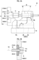
- Fig. 1 is a schematic view of a forming device 1 according to the present embodiment.
- the forming device 1 is a device that forms a metal pipe having a hollow shape by blow forming.
- the forming device 1 is installed on a horizontal plane.
- the forming device 1 includes a forming tool 2 (forming die), a drive mechanism 3, a holding unit 4, a heating unit 5, a fluid supply unit 6, a cooling unit 7, and a control unit 8.
- the metal pipe refers to a hollow article after completion of forming in the forming device 1
- a metal pipe material 40 refers to a hollow article before completion of forming in the forming device 1.
- the metal pipe material 40 is a steel-type pipe material that can be hardened.
- a direction in which the metal pipe material 40 extends during forming is sometimes referred to as an "extending direction”
- a direction perpendicular to the extending direction is sometimes referred to as a "lateral direction (second direction)".
- the forming tool 2 is a die for forming the metal pipe material 40 into the metal pipe and includes a lower die 11 (first die) and an upper die 12 (second die) facing each other in a vertical direction (first direction).
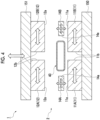
- the forming tool 2 includes a pair of lateral dies 14A and 14B (third dies) facing each other in the lateral direction (refer to Fig. 4 ).
- the lower die 11 and the upper die 12 are made of steel blocks.
- the lower die 11 is fixed to a base stage 13 via a die holder or the like.
- the upper die 12 is fixed to a slide of the drive mechanism 3 via a die holder or the like.
- the drive mechanism 3 is a mechanism that moves at least one of the lower die 11 and the upper die 12.
- the drive mechanism 3 has a configuration in which only the upper die 12 is moved.
- the drive mechanism 3 includes a slide 21 that moves the upper die 12 such that the lower die 11 and the upper die 12 are joined together, and a pull-back cylinder 22 serving as an actuator that generates a force for pulling the slide 21 upward, a main cylinder 23 serving as a drive source that downward-pressurizes the slide 21, and a drive source 24 that applies a driving force to the main cylinder 23.
- the holding unit 4 is a mechanism that holds the metal pipe material 40 disposed between the lower die 11 and the upper die 12.
- the holding unit 4 includes a lower electrode 26 and an upper electrode 27 that hold the metal pipe material 40 on one end side in the extending direction of the forming tool 2, and a lower electrode 26 and an upper electrode 27 that holds the metal pipe material 40 on the other end side in the extending direction of the forming tool 2.
- the lower electrodes 26 and the upper electrodes 27 on both sides in the extending direction hold the metal pipe material 40 by sandwiching vicinities of the end portions of the metal pipe material 40 from the vertical direction.
- groove portions having a shape corresponding to an outer peripheral surface of the metal pipe material 40 are formed on an upper surface of the lower electrode 26 and a lower surface of the upper electrode 27.
- the lower electrode 26 and the upper electrode 27 are provided with drive mechanisms (not shown) and are movable independently in the vertical direction.
- the heating unit 5 heats the metal pipe material 40.
- the heating unit 5 is a mechanism that heats the metal pipe material 40 by energizing the metal pipe material 40.
- the heating unit 5 heats the metal pipe material 40 in a state in which the metal pipe material 40 is spaced apart from the lower die 11 and the upper die 12 between the lower die 11 and the upper die 12.
- the heating unit 5 includes the lower electrodes 26 and the upper electrodes 27 on both sides in the extending direction described above, and a power supply 28 that causes a current to flow through the metal pipe material via the electrodes 26 and 27.
- the heating unit 5 may be disposed in a preceding process of the forming device 1 and may perform heating externally.
- the fluid supply unit 6 is a mechanism that supplies a high-pressure fluid into the metal pipe material 40 held between the lower die 11 and the upper die 12.
- the fluid supply unit 6 supplies the high-pressure fluid into the metal pipe material 40 that has been brought into a high-temperature state by being heated by the heating unit 5 and expands the metal pipe material 40.
- the fluid supply unit 6 is provided on both end sides of the forming tool 2 in the extending direction.
- the fluid supply unit 6 includes a nozzle 31 that supplies a fluid from an opening portion of an end portion of the metal pipe material 40 to the inside of the metal pipe material 40, a drive mechanism 32 that moves the nozzle 31 forward and backward with respect to the opening portion of the metal pipe material 40, and a supply source 33 that supplies the high-pressure fluid into the metal pipe material 40 via the nozzle 31.
- the drive mechanism 32 brings the nozzle 31 into close contact with the end portion of the metal pipe material 40 in a state in which a sealing property is secured at the time of supply and exhaust of the fluid (refer to Figs. 2A and 2B ) and at other times, separates the nozzle 31 from the end portion of the metal pipe material 40.
- the fluid supply unit 6 may supply a gas such as high-pressure air or an inert gas as the fluid. Additionally, the fluid supply unit 6 may include the heating unit 5 together with the holding unit 4 having a mechanism that moves the metal pipe material 40 in the vertical direction as the same device.
- Fig. 2A is a schematic side view showing a heating and expanding unit 50 in which components of the holding unit 4, the heating unit 5, and the fluid supply unit 6 are unitized.
- Fig. 2B is a cross-sectional view showing a state when the nozzle 31 has sealed the metal pipe material 40.
- the heating and expanding unit 50 includes the above-described lower electrode 26 and upper electrode 27, an electrode mounting unit 51 on which the electrodes 26 and 27 are mounted, the above-described nozzle 31 and drive mechanism 32, an elevating unit 52, and a unit base 53.
- the electrode mounting unit 51 includes an elevating frame 54 and electrode frames 56 and 57.
- the electrode frames 56 and 57 function as a part of a drive mechanism 60 that supports and moves each of the electrodes 26 and 27.
- the drive mechanism 32 drives the nozzle 31 and lifts and lowers together with the electrode mounting unit 51.
- the drive mechanism 32 includes a piston 61 that holds the nozzle 31, and a cylinder 62 that drives the piston.
- the elevating unit 52 includes an elevating frame base 64 attached to an upper surface of the unit base 53, and an elevating actuator 66 that applies an elevating operation to the elevating frame 54 of the electrode mounting unit 51 by the elevating frame base 64.
- the elevating frame base 64 includes guide portions 64a and 64b that guide the elevating operation of the elevating frame 54 with respect to the unit base 53.
- the elevating unit 52 functions as a part of the drive mechanism 60 of the holding unit 4.
- the heating and expanding unit 50 includes a plurality of the unit bases 53 of which upper surfaces have different inclination angles, and is allowed to collectively change and adjust inclination angles of the lower electrode 26 and the upper electrode 27, the nozzle 31, the electrode mounting unit 51, the drive mechanism 32, and the elevating unit 52 by replacing the unit bases 53.
- the nozzle 31 is a cylindrical member into which the end portion of the metal pipe material 40 can be inserted.
- the nozzle 31 is supported by the drive mechanism 32 such that a center line of the nozzle 31 coincides with a reference line SL1.
- An inner diameter of a supply port 31a at an end portion of the nozzle 31 on the side of the metal pipe material 40 substantially coincides with an outer diameter of the metal pipe material 40 after expansion forming.
- the nozzle 31 supplies the high-pressure fluid from an internal flow path 63 to the metal pipe material 40.
- the high-pressure fluid include a gas and the like.
- the cooling unit 7 is a mechanism for cooling the forming tool 2. By cooling the forming tool 2, the cooling unit 7 can rapidly cool the metal pipe material 40 when the expanded metal pipe material 40 has come into contact with a forming surface of the forming tool 2.
- the cooling unit 7 includes a flow path 36 formed inside the lower die 11 and the upper die 12, and a water circulation mechanism 37 that supplies cooling water to the flow path 36 and circulates the cooling water.
- the control unit 8 is a device that controls the entire forming device 1.
- the control unit 8 controls the drive mechanism 3, the holding unit 4, the heating unit 5, the fluid supply unit 6, and the cooling unit 7.
- the control unit 8 repeatedly performs an operation of forming the metal pipe material 40 with the forming tool 2.
- control unit 8 controls, for example, a transport timing from a transport device such as a robot arm to dispose the metal pipe material 40 between the lower die 11 and the upper die 12 in an open state. Alternatively, the control unit 8 may wait for a worker to manually dispose the metal pipe material 40 between the lower die 11 and the upper die 12. Additionally, the control unit 8 controls an actuator of the holding unit 4 and the like such that the metal pipe material 40 is supported by the lower electrodes 26 on both sides in the extending direction, and then the upper electrodes 27 are lowered to sandwich the metal pipe material 40. Additionally, the control unit 8 controls the heating unit 5 to energize and heat the metal pipe material 40. Accordingly, an axial current flows through the metal pipe material 40, and an electric resistance of the metal pipe material 40 itself causes the metal pipe material 40 itself to generate heat due to Joule heat.
- the control unit 8 controls the drive mechanism 3 to lower the upper die 12 and bring the upper die 12 close to the lower die 11 to close the forming tool 2.
- the control unit 8 controls the fluid supply unit 6 to seal the opening portions of both ends of the metal pipe material 40 with the nozzle 31 and supply the fluid. Accordingly, the metal pipe material 40 softened by heating expands and comes into contact with the forming surface of the forming tool 2. Then, the metal pipe material 40 is formed so as to follow a shape of the forming surface of the forming tool 2. When the metal pipe material 40 comes into contact with the forming surface, quenching of the metal pipe material 40 is performed by being rapidly cooled with the forming tool 2 cooled by the cooling unit 7.
- the metal pipe 41 formed by the forming device 1 will be described with reference to Fig. 3 .
- the metal pipe 41 includes a hollow pipe portion 41a and flange portions 41b and 41c.
- the pipe portion 41a has a rectangular shape extending in a longitudinal direction and a transverse direction.
- the flange portions 41b and 41c are formed by crushing both end portions of the metal pipe material 40.
- locations that are planned to become the flange portions 41b and 41c after completion in the metal pipe material 40 are referred to as flange portions 40b and 40c (refer to Figs. 5 and 6 ).
- the metal pipe material 40 has a rectangular shape in a cross-sectional view.
- the metal pipe material 40 is disposed with respect to the forming tool 2 such that the longitudinal direction thereof is parallel to the lateral direction of the forming device 1 and the transverse direction thereof is parallel to the vertical direction of the forming device 1 in a cross-sectional view. Therefore, the metal pipe 41 immediately after completion is also disposed with respect to the forming tool 2 such that the longitudinal direction thereof is parallel to the lateral direction of the forming device 1 and the transverse direction thereof is parallel to the vertical direction of the forming device 1 (refer to Fig. 7 ).
- the lower die 11 is fixed to a base member 150 provided on the base stage 13 (refer to Fig. 1 ).
- the lower die 11 includes a first portion 11A and a second portion 11B that are divided in the lateral direction and form a flange portion 41b by sandwiching a part of a lower wall portion of the metal pipe material 40 in the lateral direction.
- the first portion 11A and the second portion 11B each include a pipe portion forming surface 11a that extends parallel to the lateral direction at an upper end portion and a flange portion forming surface 11b that extends parallel to the vertical direction on an inner side in the lateral direction.
- the pipe portion forming surface 11a is a forming surface for forming a lower wall portion of the metal pipe 41.
- the flange portion forming surface 11b is a forming surface for forming the flange portion 41b on a lower side of the metal pipe 41.
- the first portion 11A and the second portion 11B can reciprocate in the lateral direction.
- the upper die 12 is fixed to a base member 151 provided on the slide 21 (refer to Fig. 1 ).
- the upper die 12 includes a first portion 12A and a second portion 12B that are divided in the lateral direction and form a flange portion 41c by sandwiching a part of an upper wall portion of the metal pipe material 40 in the lateral direction.
- the first portion 12A and the second portion 12B include a pipe portion forming surface 12a that extends parallel to the lateral direction at a lower end portion and a flange portion forming surface 12b that extends parallel to the vertical direction on an inner side in the lateral direction.
- the pipe portion forming surface 12a is a forming surface for forming an upper wall portion of the metal pipe 41.
- the flange portion forming surface 12b is a forming surface for forming the flange portion 41c on an upper side of the metal pipe 41.
- the first portion 12A and the second portion 12B can reciprocate in the lateral direction.
- the first portion 12A and the second portion 12B can reciprocate in the vertical direction as the base member 151 reciprocates in the vertical direction together with the slide 21 (refer to Fig. 1 ).
- the die 14A on a lateral side is disposed on one side of the metal pipe material 40 in the lateral direction.
- the die 14B on a lateral side is disposed on the other side of the metal pipe material 40 in the lateral direction.
- the die 14A is disposed between the pipe portion forming surface 11a of the first portion 11A and the pipe portion forming surface 12a of the first portion 12A in the vertical direction.
- the die 14B is disposed between the pipe portion forming surface 11a of the second portion 11B and the pipe portion forming surface 12a of the second portion 12B in the vertical direction.
- the dies 14A and 14B each have a pipe portion forming surface 14a that extends parallel to the vertical direction on an inner side in the lateral direction.
- the dies 14A and 14B can reciprocate in the lateral direction and reciprocate in the vertical direction. Lower surfaces of the dies 14A and 14B come into surface contact with the pipe portion forming surface 11a of the lower die 11. Upper surfaces of the dies 14A and 14B come into surface contact with the pipe portion forming surface 12a of the upper die 12.
- the lateral movements of the respective portions 11A, 11B, 12A, and 12B and the dies 14A and 14B are performed simultaneously or at different timings.
- the lateral movements of the respective portions 11A, 11B, 12A, and 12B and the dies 14A and 14B may be performed by individually providing a drive source for each member.
- a wedge mechanism may be provided such that the respective portions 11A, 11B, 12A, and 12B and the dies 14A and 14B are closed in the lateral direction as the slide 21 lowers the upper die 12.
- a spring mechanism may be provided such that the respective portions 11A, 11B, 12A, and 12B and the dies 14A and 14B open in the lateral direction when the slide 21 raises the upper die 12.
- the metal pipe material 40 is set in an internal space of the forming tool 2.
- the respective dies 11, 12, 14A, and 14B are disposed at positions separated from the metal pipe material 40.
- the control unit 8 lowers the upper die 12 from the state shown in Fig. 4 to a position separated from the metal pipe material 40, and heats the metal pipe material 40 in this state.
- the control unit 8 lowers the die 12, the dies 14A and 14B, and the metal pipe material 40 downward.
- the pipe portion forming surface 12a of the die 12 comes into contact with the upper wall portion of the metal pipe material 40
- the pipe portion forming surface 11a of the die 11 comes into contact with the lower wall portion of the metal pipe material 40
- the pipe portion forming surfaces 14a of the dies 14A and 14B come into contact with side wall portions of the metal pipe material 40.
- the control unit 8 controls the fluid supply unit 6 to supply the fluid into the metal pipe material 40 to perform blow forming (primary blowing).
- the portions of the flange portions 40b and 40c of the metal pipe material 40 on both sides in the vertical direction expand so as to enter between a pair of the flange portion forming surfaces 11b of the die 11 and enter between a pair of the flange portion forming surfaces 12b of the die 12.
- the side wall portions on both sides of the metal pipe material 40 come into contact with the pipe portion forming surfaces 14a of the dies 14A and 14B, so that further outward deformation in the lateral direction is restricted.
- the control unit 8 further lowers the die 12 and the dies 14A and 14B downward. Accordingly, the portions 11A and 11B of the die 11 come into contact with the dies 14A and 14B in the vertical direction, and the portions 12A and 12B of the die 12 come into contact with the dies 14A and 14B in the vertical direction.
- the control unit 8 moves the portions 11A and 11B inward in the lateral direction and moves the portions 12A and 12B inward in the lateral direction. Accordingly, the flange portion forming surfaces 11b of the portions 11A and 11B sandwich and crush the flange portion 40b of the metal pipe material 40. The flange portion forming surfaces 12b of the portions 12A and 12B sandwich and crush the flange portion 40c of the metal pipe material 40. Accordingly, the flange portions 41b and 41c of the metal pipe 41 are formed.
- the control unit 8 controls the fluid supply unit 6 to supply the fluid into the pipe portion 40a of the metal pipe material 40 to perform blow forming (secondary blowing). Accordingly, the pipe portion 41a of the metal pipe 41 is formed. As described above, the metal pipe 41 is completed.
- the forming tool 2 includes the lower die 11 and the upper die 12 facing each other in the vertical direction and includes the dies 14A and 14B disposed on both sides of the metal pipe material 40 in the lateral direction intersecting the vertical direction in a cross-sectional view.
- the die 11 and the die 12 can form a shape of the pipe portion 41a in the vertical direction of the metal pipe 41.
- the dies 14A and 14B can form a shape of the pipe portion 41a in the lateral direction of the metal pipe 41.
- the die 11 and the die 12 include the first portions 11A and 12B and the second portions 11B and 12B that are divided in the lateral direction and form the flange portions 41b and 41c by sandwiching a part of the metal pipe material 40 in the lateral direction. Therefore, it is possible to form the flange portions 41b and 41c that protrude in the vertical direction which is a direction in which the die 11 and the die 12 face each other. Accordingly, it is possible to form the flange portions 41b and 41c which can secure a strength and a rigidity in accordance with a direction of a load acting on the metal pipe 41 during use. As described above, the strength and the rigidity of the metal pipe 41 with a flange can be improved.
- the metal pipe 41 includes the hollow pipe portion 41a that extends in the longitudinal direction and the flange portion 41b and 41c that protrude from the pipe portion 41a to both sides in the transverse direction perpendicular to the longitudinal direction in a cross-sectional view.
- the flange portions 41b and 41c of the pipe portion 41a that protrude in the transverse direction from a wall portion (wall portion forming a long side) extending in the longitudinal direction in a cross-sectional view can be formed. Since the metal pipe 41 is sometimes used in a vehicle frame, there is a possibility that a load acts on the long side of the metal pipe 41. If there is no flange portion on the long side, the metal pipe is easily deformed. However, by forming the flange portion, it is possible to improve the strength and the rigidity without being easily deformed. In addition, since the flange portion is formed along the longitudinal direction, the strength and the rigidity of the metal pipe 41 can be improved for a load in the longitudinal direction.
- Both the lower die 11 and the upper die 12 may include the first portions 11A and 12A and the second portions 11B and 12B. Accordingly, the flange portions 41b and 41c can be formed on both sides in the vertical direction with respect to the pipe portion 41a to improve the strength and the rigidity of the metal pipe 41.
- the metal pipe 41 may include a pair of the flange portions 41b and 41c protruding from the pipe portion 41a to both sides in the transverse direction. Accordingly, the strength and the rigidity of the metal pipe 41 can be improved.
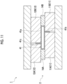
- the forming device 1 as shown in Figs. 8 to 11 may be adopted.
- the metal pipe 41 shown in Fig. 11 may be formed thereby.
- the first portion 11A and the second portion 11B in the lower die 11 and the first portion 12A and the second portion 12B in the upper die 12 form the flange portions 41b and 41c at positions different from each other in the lateral direction.
- a pair of the flange portions 41b and 41c are formed at positions different from each other in the longitudinal direction.
- the first portion 11A is larger than the second portion 11B. Therefore, as shown in Fig. 11 , the lower flange portion 41b is formed at a position closer to the die 14B side in the lateral direction (longitudinal direction) with respect to the pipe portion 41a.
- the upper flange portion 41c is formed at a position closer to the die 14A side in the lateral direction (longitudinal direction) with respect to the pipe portion 41a.
- the operation of the forming device 1 in Figs. 8 to 11 is the same as the operation in Figs. 4 to 7 .
- the forming device 1 as shown in Figs. 12 to 15 may be adopted.
- the metal pipe 41 shown in Fig. 15 may be formed thereby.
- the first portions 11A and 12A and the second portions 11B and 12B may form the flange portions 41b and 41c at the same position as one side surface 41d in the lateral direction (longitudinal direction) of the metal pipe 41 (refer to Fig. 15 ).
- the same stress is generated for a load from a target direction (a load such as a bending load), and the shape can be balanced in terms of strength.
- the first portions 11A and 12A are smaller than the second portions 11B and 12B. Therefore, as shown in Fig. 15 , the flange portions 41b and 41c on both sides are formed at positions closer to the die 14A side in the lateral direction (longitudinal direction) with respect to the pipe portion 41a. Then, the flange portions 41b and 41c protrude in the vertical direction such that one side surface 41d in the lateral direction (longitudinal direction) of the pipe portion 41a extends in the vertical direction (transverse direction) as it is.
- the operation of the forming device 1 in Figs. 12 to 15 is the same as the operation in Figs. 4 to 7 .
- the die 14A may be integrally formed with the upper die 12A, or conversely, the die 14A may be integrally formed with the lower die 11A.
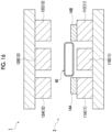
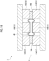
- the forming device 1 as shown in Figs. 16 to 19 may be adopted.
- the metal pipe 41 shown in Fig. 19 may be formed thereby.
- the lower die 11 and the upper die 12 may include third portions 11C and 12C that form another flange portions 41b and 41c by sandwiching another part of the metal pipe material 40 with the second portions 11B and 12B.
- a plurality of (here, two each) flange portions 41b and 41c protruding to both sides in the vertical direction (transverse direction) may be formed at positions different from each other in the lateral direction (longitudinal direction). In this case, the number of the flange portions 41b and 41c can be increased to increase the strength and the rigidity.
- the lower die 11 is divided into three parts, and the upper die 12 is divided into three parts.
- the first portions 11A and 12A are smaller than the second portions 11B and 12B. Therefore, as shown in Fig. 19 , the flange portions 41b and 41c relating to one set are formed at positions closer to the die 14A side in the lateral direction (longitudinal direction) with respect to the pipe portion 41a. Then, the flange portions 41b and 41c relating to one set protrude in the vertical direction such that one side surface 41d in the lateral direction (longitudinal direction) of the pipe portion 41a extends in the vertical direction (transverse direction) as it is.
- the flange portions 41b and 41c relating to the other set are formed at positions closer to the die 14B side in the lateral direction (longitudinal direction) with respect to the pipe portion 41a. Then, the flange portions 41b and 41c relating to the other set protrude in the vertical direction such that the other side surface 41e in the lateral direction (longitudinal direction) of the pipe portion 41a extends in the vertical direction (transverse direction) as it is.
- the operation of the forming device 1 in Figs. 16 to 19 is the same as the operation in Figs. 4 to 7 .
- the dies 14A and 14B may be integrally formed with the upper dies 12A and 12C, or conversely, the dies 14A and 14B may be integrally formed with the lower dies 11A and 11C.
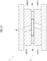
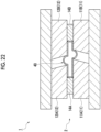
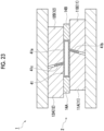
- the forming device 1 as shown in Figs. 20 to 23 may be adopted.
- the metal pipe 41 shown in Fig. 23 may be formed thereby.
- the first portions 11A and 12A and the second portions 11B and 12B form the flange portions 41b and 41c that are inclined with respect to the vertical direction.
- the flange portions 41b and 41c protrude so as to be inclined with respect to the transverse direction.
- the rigidity can be increased, and a deformation behavior of a formed body depending on a direction of a load applied to the metal pipe can be controlled in a more preferable direction.
- the flange portion forming surfaces 11b of the first portion 11A and the second portion 11B extend in a state of being inclined with respect to the vertical direction.
- the flange portion forming surfaces 12b of the first portion 12A and the second portion 12B extend in a state of being inclined with respect to the vertical direction. Therefore, as shown in Fig. 23 , the flange portions 41b and 41c on both sides protrude so as to be inclined with respect to upper and lower side surfaces of the pipe portion 41a.
- the operation of the forming device 1 in Figs. 20 to 23 is the same as the operation in Figs. 4 to 7 .
- the type of the forming device in which the forming tool according to the present disclosure is adopted is not particularly limited, and may be any type of the forming device that supplies a fluid to expand the metal pipe material.
- a facing direction between the first die and the second die does not have to be the vertical direction and may be the horizontal direction.
- each drawing is merely an example, and may be appropriately changed without departing from the concept of the disclosure of the present application.
- an operation timing and a contact state of each die may be appropriately changed.
- the dies 14A and 14B are in contact with the dies 11 and 12 so as to be sandwiched therebetween in a completely closed state, but in the meantime, the dies 14A and 14B may be in any contact state with respect to the dies 11 and 12.
Landscapes
- Engineering & Computer Science (AREA)
- Mechanical Engineering (AREA)
- Physics & Mathematics (AREA)
- Fluid Mechanics (AREA)
- Shaping Metal By Deep-Drawing, Or The Like (AREA)
- Mounting, Exchange, And Manufacturing Of Dies (AREA)
Abstract
Description
- The present disclosure relates to a forming device and a metal pipe.
- In the related art, a forming device used for forming a metal pipe is known. For example,
PTL 1 described below discloses a forming device that includes a forming tool including a lower die and an upper die paired with each other, and a fluid supply unit for supplying a fluid into a metal pipe material held between the upper and lower dies. - [PTL 1]
Japanese Unexamined Patent Publication No. 2009-220141 - In the forming device such as the related art described above, there is a case where the metal pipe with a flange is formed by crushing both sides of the metal pipe material in a lateral direction with the upper die and the lower die. In such a forming device, it has been required to further improve a strength and a rigidity of the metal pipe with a flange.
- The present disclosure has been made to solve such a problem, and an object of the present disclosure is to provide a forming device capable of improving the strength and the rigidity of the metal pipe with a flange and a metal pipe capable of improving the strength and the rigidity.
- A forming device according to an aspect of the present disclosure forms a metal pipe with a flange and includes a forming tool for forming the metal pipe, in which the forming tool includes a first die and a second die facing each other in a first direction in a cross-sectional view, and a third die disposed on at least one side of a metal pipe material in a second direction intersecting the first direction, and at least one of the first die and the second die is divided in the second direction and sandwiches a part of the metal pipe material in the second direction to form a flange portion.
- In the forming device, the forming tool includes the first die and the second die facing each other in the first direction in a cross-sectional view, and the third die disposed on at least one side of the metal pipe material in the second direction intersecting the first direction. The first die and the second die can form a shape of a pipe portion in the first direction of the metal pipe. In addition, the third die can form a shape of the pipe portion in the second direction of the metal pipe. Here, at least one of the first die and the second die is divided in the second direction and sandwiches a part of the metal pipe material in the second direction to form the flange portion. Therefore, it is possible to form the flange portion that protrudes in the first direction which is a direction in which the first die and the second die face each other. Accordingly, it is possible to form the flange portion that can secure a strength and a rigidity in accordance with a direction of a load acting on the metal pipe during use. As described above, the strength and rigidity of the metal pipe with a flange can be improved.
- At least one of the first die and the second die may include a first portion and a second portion that sandwich a part of the metal pipe material in the second direction to form the flange portion. Accordingly, it is possible to form the flange portion that protrudes in the first direction which is a direction in which the first die and the second die face each other.
- Both the first die and the second die may have the first portion and the second portion. Accordingly, it is possible to form the flange portions on both sides in the first direction with respect to the pipe portion to improve the strength and the rigidity of the metal pipe.
- The first portion and the second portion in the first die, and the first portion and the second portion in the second die may form the flange portions at positions different from each other in the second direction. In this case, it is possible to adjust positions where the strength and the rigidity are increased with the flange portions in the second direction on one side and the other side in the first direction of the pipe portion. In addition, it is also possible to control a deformation behavior of the metal pipe depending on a direction of a load applied to the metal pipe.
- The first portion and the second portion may form the flange portion at the same position as one side surface in the second direction of the metal pipe. In this case, it is possible to control a deformation behavior of the metal pipe depending on a direction of a load applied to the metal pipe in a case where there is a shape limitation such that a position of the flange portion is only at an end in terms of position.
- At least one of the first die and the second die may include a third portion that sandwiches another part of the metal pipe material with the second portion to form another flange portion. In this case, the number of the flange portions can be increased to increase the strength and the rigidity.
- The first portion and the second portion may form the flange portion inclined with respect to the first direction. In this case, the rigidity can be increased, and a deformation behavior of a formed body depending on a direction of a load applied to the metal pipe can be controlled in a more preferable direction.
- A metal pipe according to the present disclosure includes a hollow pipe portion that extends in a longitudinal direction in a cross-sectional view, and a flange portion that protrudes from the pipe portion to at least one side in a transverse direction perpendicular to the longitudinal direction.
- In this metal pipe, the flange portion of the pipe portion that protrudes in the transverse direction from a wall portion extending in the longitudinal direction in a cross-sectional view can be formed. Therefore, the strength and the rigidity of the metal pipe can be improved for a load in the longitudinal direction.
- The metal pipe may include a pair of the flange portions protruding from the pipe portion to both sides in the transverse direction. Accordingly, the strength and the rigidity of the metal pipe can be improved.
- The pair of flange portions may be formed at positions different from each other in the longitudinal direction. In this case, it is possible to adjust positions where the strength and the rigidity are increased with the flange portions in the longitudinal direction on one side and the other side in the transverse direction of the pipe portion.
- The flange portion may be formed at the same position as one side surface in the longitudinal direction of the pipe portion. In this case, the same stress is generated for a load from a target direction (a load such as a bending load), and the shape can be balanced in terms of strength.
- A plurality of the flange portions protruding to at least one side in the transverse direction may be formed in the pipe portion at positions different from each other in the longitudinal direction. In this case, the number of the flange portions can be increased to increase the strength and the rigidity.
- The flange portion may be inclined with respect to the transverse direction. In this case, even if the rigidity and the strength are inferior to those in a case where the flange portions are in the vertical direction, there is a case where it is more convenient to have a certain inclination angle in joining with ancillary parts, and it is possible to meet design requirements. In addition, there is a possibility that the deformation behavior can be optimized depending on the direction of the load and the inclination of the flange portion.
- According to the present disclosure, it is possible to provide a forming device capable of improving the strength and the rigidity of a metal pipe with a flange and a metal pipe capable of improving the strength and the rigidity.
-
-
Fig. 1 is a schematic view of a forming device according to an embodiment of the present disclosure. -
Figs. 2A and 2B are cross-sectional views showing a state when a nozzle has sealed a metal pipe material. -
Fig. 3 is a schematic perspective view of a metal pipe. -
Fig. 4 is a cross-sectional view showing a state of forming by a forming tool. -
Fig. 5 is a cross-sectional view showing a state of forming by the forming tool. -
Fig. 6 is a cross-sectional view showing a state of forming by the forming tool. -
Fig. 7 is a cross-sectional view showing a state of forming by the forming tool. -
Fig. 8 is a cross-sectional view showing a state of forming by the forming tool. -
Fig. 9 is a cross-sectional view showing a state of forming by the forming tool. -
Fig. 10 is a cross-sectional view showing a state of forming by the forming tool. -
Fig. 11 is a cross-sectional view showing a state of forming by the forming tool. -
Fig. 12 is a cross-sectional view showing a state of forming by the forming tool. -
Fig. 13 is a cross-sectional view showing a state of forming by the forming tool. -
FIG. 14 is a cross-sectional view showing a state of forming by the forming tool. -
Fig. 15 is a cross-sectional view showing a state of forming by the forming tool. -
Fig. 16 is a cross-sectional view showing a state of forming by the forming tool. -
Fig. 17 is a cross-sectional view showing a state of forming by the forming tool. -
Fig. 18 is a cross-sectional view showing a state of forming by the forming tool. -
Fig. 19 is a cross-sectional view showing a state of forming by the forming tool. -
Fig. 20 is a cross-sectional view showing a state of forming by the forming tool. -
Fig. 21 is a cross-sectional view showing a state of forming by the forming tool. -
Fig. 22 is a cross-sectional view showing a state of forming by the forming tool. -
Fig. 23 is a cross-sectional view showing a state of forming by the forming tool. - Hereinafter, a preferred embodiment of the present disclosure will be described with reference to the drawings. In addition, in the respective drawings, the same portions or corresponding portions are designated by the same reference signs, and duplicated descriptions will not be repeated.
-
Fig. 1 is a schematic view of a formingdevice 1 according to the present embodiment. As shown inFig. 1 , the formingdevice 1 is a device that forms a metal pipe having a hollow shape by blow forming. In the present embodiment, the formingdevice 1 is installed on a horizontal plane. The formingdevice 1 includes a forming tool 2 (forming die), adrive mechanism 3, a holding unit 4, aheating unit 5, afluid supply unit 6, acooling unit 7, and acontrol unit 8. In addition, in the present specification, the metal pipe refers to a hollow article after completion of forming in the formingdevice 1, and ametal pipe material 40 refers to a hollow article before completion of forming in the formingdevice 1. Themetal pipe material 40 is a steel-type pipe material that can be hardened. In addition, in a horizontal direction, a direction in which themetal pipe material 40 extends during forming is sometimes referred to as an "extending direction", and a direction perpendicular to the extending direction is sometimes referred to as a "lateral direction (second direction)". - The forming
tool 2 is a die for forming themetal pipe material 40 into the metal pipe and includes a lower die 11 (first die) and an upper die 12 (second die) facing each other in a vertical direction (first direction). In addition, the formingtool 2 includes a pair of lateral dies 14A and 14B (third dies) facing each other in the lateral direction (refer toFig. 4 ). Detailed shapes and the like of the dies 11, 12, 14A, and 14B will be described later. Thelower die 11 and theupper die 12 are made of steel blocks. Thelower die 11 is fixed to abase stage 13 via a die holder or the like. Theupper die 12 is fixed to a slide of thedrive mechanism 3 via a die holder or the like. - The
drive mechanism 3 is a mechanism that moves at least one of thelower die 11 and theupper die 12. InFig. 1 , thedrive mechanism 3 has a configuration in which only theupper die 12 is moved. Thedrive mechanism 3 includes aslide 21 that moves theupper die 12 such that thelower die 11 and theupper die 12 are joined together, and a pull-back cylinder 22 serving as an actuator that generates a force for pulling theslide 21 upward, amain cylinder 23 serving as a drive source that downward-pressurizes theslide 21, and adrive source 24 that applies a driving force to themain cylinder 23. - The holding unit 4 is a mechanism that holds the
metal pipe material 40 disposed between thelower die 11 and theupper die 12. The holding unit 4 includes a lower electrode 26 and an upper electrode 27 that hold themetal pipe material 40 on one end side in the extending direction of the formingtool 2, and a lower electrode 26 and an upper electrode 27 that holds themetal pipe material 40 on the other end side in the extending direction of the formingtool 2. The lower electrodes 26 and the upper electrodes 27 on both sides in the extending direction hold themetal pipe material 40 by sandwiching vicinities of the end portions of themetal pipe material 40 from the vertical direction. In addition, groove portions having a shape corresponding to an outer peripheral surface of themetal pipe material 40 are formed on an upper surface of the lower electrode 26 and a lower surface of the upper electrode 27. The lower electrode 26 and the upper electrode 27 are provided with drive mechanisms (not shown) and are movable independently in the vertical direction. - The
heating unit 5 heats themetal pipe material 40. Theheating unit 5 is a mechanism that heats themetal pipe material 40 by energizing themetal pipe material 40. Theheating unit 5 heats themetal pipe material 40 in a state in which themetal pipe material 40 is spaced apart from thelower die 11 and theupper die 12 between thelower die 11 and theupper die 12. Theheating unit 5 includes the lower electrodes 26 and the upper electrodes 27 on both sides in the extending direction described above, and apower supply 28 that causes a current to flow through the metal pipe material via the electrodes 26 and 27. In addition, theheating unit 5 may be disposed in a preceding process of the formingdevice 1 and may perform heating externally. - The
fluid supply unit 6 is a mechanism that supplies a high-pressure fluid into themetal pipe material 40 held between thelower die 11 and theupper die 12. Thefluid supply unit 6 supplies the high-pressure fluid into themetal pipe material 40 that has been brought into a high-temperature state by being heated by theheating unit 5 and expands themetal pipe material 40. Thefluid supply unit 6 is provided on both end sides of the formingtool 2 in the extending direction. Thefluid supply unit 6 includes anozzle 31 that supplies a fluid from an opening portion of an end portion of themetal pipe material 40 to the inside of themetal pipe material 40, adrive mechanism 32 that moves thenozzle 31 forward and backward with respect to the opening portion of themetal pipe material 40, and asupply source 33 that supplies the high-pressure fluid into themetal pipe material 40 via thenozzle 31. Thedrive mechanism 32 brings thenozzle 31 into close contact with the end portion of themetal pipe material 40 in a state in which a sealing property is secured at the time of supply and exhaust of the fluid (refer toFigs. 2A and 2B ) and at other times, separates thenozzle 31 from the end portion of themetal pipe material 40. In addition, thefluid supply unit 6 may supply a gas such as high-pressure air or an inert gas as the fluid. Additionally, thefluid supply unit 6 may include theheating unit 5 together with the holding unit 4 having a mechanism that moves themetal pipe material 40 in the vertical direction as the same device. -
Fig. 2A is a schematic side view showing a heating and expandingunit 50 in which components of the holding unit 4, theheating unit 5, and thefluid supply unit 6 are unitized.Fig. 2B is a cross-sectional view showing a state when thenozzle 31 has sealed themetal pipe material 40. - As shown in
Fig. 2A , the heating and expandingunit 50 includes the above-described lower electrode 26 and upper electrode 27, anelectrode mounting unit 51 on which the electrodes 26 and 27 are mounted, the above-describednozzle 31 anddrive mechanism 32, an elevating unit 52, and aunit base 53. Theelectrode mounting unit 51 includes an elevatingframe 54 and electrode frames 56 and 57. The electrode frames 56 and 57 function as a part of a drive mechanism 60 that supports and moves each of the electrodes 26 and 27. Thedrive mechanism 32 drives thenozzle 31 and lifts and lowers together with theelectrode mounting unit 51. Thedrive mechanism 32 includes apiston 61 that holds thenozzle 31, and acylinder 62 that drives the piston. The elevating unit 52 includes an elevatingframe base 64 attached to an upper surface of theunit base 53, and an elevatingactuator 66 that applies an elevating operation to the elevatingframe 54 of theelectrode mounting unit 51 by the elevatingframe base 64. The elevatingframe base 64 includesguide portions frame 54 with respect to theunit base 53. The elevating unit 52 functions as a part of the drive mechanism 60 of the holding unit 4. The heating and expandingunit 50 includes a plurality of the unit bases 53 of which upper surfaces have different inclination angles, and is allowed to collectively change and adjust inclination angles of the lower electrode 26 and the upper electrode 27, thenozzle 31, theelectrode mounting unit 51, thedrive mechanism 32, and the elevating unit 52 by replacing the unit bases 53. - The
nozzle 31 is a cylindrical member into which the end portion of themetal pipe material 40 can be inserted. Thenozzle 31 is supported by thedrive mechanism 32 such that a center line of thenozzle 31 coincides with a reference line SL1. An inner diameter of asupply port 31a at an end portion of thenozzle 31 on the side of themetal pipe material 40 substantially coincides with an outer diameter of themetal pipe material 40 after expansion forming. In this state, thenozzle 31 supplies the high-pressure fluid from aninternal flow path 63 to themetal pipe material 40. Examples of the high-pressure fluid include a gas and the like. - Returning to
Fig. 1 , thecooling unit 7 is a mechanism for cooling the formingtool 2. By cooling the formingtool 2, thecooling unit 7 can rapidly cool themetal pipe material 40 when the expandedmetal pipe material 40 has come into contact with a forming surface of the formingtool 2. Thecooling unit 7 includes aflow path 36 formed inside thelower die 11 and theupper die 12, and awater circulation mechanism 37 that supplies cooling water to theflow path 36 and circulates the cooling water. - The
control unit 8 is a device that controls the entire formingdevice 1. Thecontrol unit 8 controls thedrive mechanism 3, the holding unit 4, theheating unit 5, thefluid supply unit 6, and thecooling unit 7. Thecontrol unit 8 repeatedly performs an operation of forming themetal pipe material 40 with the formingtool 2. - Specifically, the
control unit 8 controls, for example, a transport timing from a transport device such as a robot arm to dispose themetal pipe material 40 between thelower die 11 and theupper die 12 in an open state. Alternatively, thecontrol unit 8 may wait for a worker to manually dispose themetal pipe material 40 between thelower die 11 and theupper die 12. Additionally, thecontrol unit 8 controls an actuator of the holding unit 4 and the like such that themetal pipe material 40 is supported by the lower electrodes 26 on both sides in the extending direction, and then the upper electrodes 27 are lowered to sandwich themetal pipe material 40. Additionally, thecontrol unit 8 controls theheating unit 5 to energize and heat themetal pipe material 40. Accordingly, an axial current flows through themetal pipe material 40, and an electric resistance of themetal pipe material 40 itself causes themetal pipe material 40 itself to generate heat due to Joule heat. - The
control unit 8 controls thedrive mechanism 3 to lower theupper die 12 and bring theupper die 12 close to thelower die 11 to close the formingtool 2. On the other hand, thecontrol unit 8 controls thefluid supply unit 6 to seal the opening portions of both ends of themetal pipe material 40 with thenozzle 31 and supply the fluid. Accordingly, themetal pipe material 40 softened by heating expands and comes into contact with the forming surface of the formingtool 2. Then, themetal pipe material 40 is formed so as to follow a shape of the forming surface of the formingtool 2. When themetal pipe material 40 comes into contact with the forming surface, quenching of themetal pipe material 40 is performed by being rapidly cooled with the formingtool 2 cooled by thecooling unit 7. - A
metal pipe 41 formed by the formingdevice 1 will be described with reference toFig. 3 . Themetal pipe 41 includes ahollow pipe portion 41a andflange portions Fig. 7 ), thepipe portion 41a has a rectangular shape extending in a longitudinal direction and a transverse direction. Theflange portions metal pipe material 40. In the following description, locations that are planned to become theflange portions metal pipe material 40 are referred to asflange portions Figs. 5 and6 ). - In the present embodiment, as shown in
Fig. 4 , themetal pipe material 40 has a rectangular shape in a cross-sectional view. Themetal pipe material 40 is disposed with respect to the formingtool 2 such that the longitudinal direction thereof is parallel to the lateral direction of the formingdevice 1 and the transverse direction thereof is parallel to the vertical direction of the formingdevice 1 in a cross-sectional view. Therefore, themetal pipe 41 immediately after completion is also disposed with respect to the formingtool 2 such that the longitudinal direction thereof is parallel to the lateral direction of the formingdevice 1 and the transverse direction thereof is parallel to the vertical direction of the forming device 1 (refer toFig. 7 ). In the following description, in a case where terms "upper", "lower", and "lateral" are used for themetal pipe 41 and themetal pipe material 40, a posture when themetal pipe 41 and themetal pipe material 40 are disposed in the formingtool 2 is assumed to be a reference. - Next, a configuration of the forming
tool 2 will be described in detail with reference toFig. 4 . Thelower die 11 is fixed to abase member 150 provided on the base stage 13 (refer toFig. 1 ). Thelower die 11 includes afirst portion 11A and asecond portion 11B that are divided in the lateral direction and form aflange portion 41b by sandwiching a part of a lower wall portion of themetal pipe material 40 in the lateral direction. Thefirst portion 11A and thesecond portion 11B each include a pipeportion forming surface 11a that extends parallel to the lateral direction at an upper end portion and a flangeportion forming surface 11b that extends parallel to the vertical direction on an inner side in the lateral direction. The pipeportion forming surface 11a is a forming surface for forming a lower wall portion of themetal pipe 41. The flangeportion forming surface 11b is a forming surface for forming theflange portion 41b on a lower side of themetal pipe 41. Thefirst portion 11A and thesecond portion 11B can reciprocate in the lateral direction. - The
upper die 12 is fixed to abase member 151 provided on the slide 21 (refer toFig. 1 ). Theupper die 12 includes afirst portion 12A and asecond portion 12B that are divided in the lateral direction and form aflange portion 41c by sandwiching a part of an upper wall portion of themetal pipe material 40 in the lateral direction. Thefirst portion 12A and thesecond portion 12B include a pipeportion forming surface 12a that extends parallel to the lateral direction at a lower end portion and a flangeportion forming surface 12b that extends parallel to the vertical direction on an inner side in the lateral direction. The pipeportion forming surface 12a is a forming surface for forming an upper wall portion of themetal pipe 41. The flangeportion forming surface 12b is a forming surface for forming theflange portion 41c on an upper side of themetal pipe 41. Thefirst portion 12A and thesecond portion 12B can reciprocate in the lateral direction. In addition, thefirst portion 12A and thesecond portion 12B can reciprocate in the vertical direction as thebase member 151 reciprocates in the vertical direction together with the slide 21 (refer toFig. 1 ). - The
die 14A on a lateral side is disposed on one side of themetal pipe material 40 in the lateral direction. Thedie 14B on a lateral side is disposed on the other side of themetal pipe material 40 in the lateral direction. Thedie 14A is disposed between the pipeportion forming surface 11a of thefirst portion 11A and the pipeportion forming surface 12a of thefirst portion 12A in the vertical direction. Thedie 14B is disposed between the pipeportion forming surface 11a of thesecond portion 11B and the pipeportion forming surface 12a of thesecond portion 12B in the vertical direction. The dies 14A and 14B each have a pipeportion forming surface 14a that extends parallel to the vertical direction on an inner side in the lateral direction. The dies 14A and 14B can reciprocate in the lateral direction and reciprocate in the vertical direction. Lower surfaces of the dies 14A and 14B come into surface contact with the pipeportion forming surface 11a of thelower die 11. Upper surfaces of the dies 14A and 14B come into surface contact with the pipeportion forming surface 12a of theupper die 12. - The lateral movements of the
respective portions respective portions respective portions slide 21 lowers theupper die 12. In this case, a spring mechanism may be provided such that therespective portions slide 21 raises theupper die 12. - Next, a procedure for forming with the forming
tool 2 will be described. First, as shown inFig. 4 , themetal pipe material 40 is set in an internal space of the formingtool 2. As shown inFig. 4 , in an initial forming state, the respective dies 11, 12, 14A, and 14B are disposed at positions separated from themetal pipe material 40. Thecontrol unit 8 lowers the upper die 12 from the state shown inFig. 4 to a position separated from themetal pipe material 40, and heats themetal pipe material 40 in this state. - Next, as shown in
Fig. 5 , thecontrol unit 8 lowers the die 12, the dies 14A and 14B, and themetal pipe material 40 downward. At this time, the pipeportion forming surface 12a of the die 12 comes into contact with the upper wall portion of themetal pipe material 40, the pipeportion forming surface 11a of the die 11 comes into contact with the lower wall portion of themetal pipe material 40, and the pipeportion forming surfaces 14a of the dies 14A and 14B come into contact with side wall portions of themetal pipe material 40. In addition, thecontrol unit 8 controls thefluid supply unit 6 to supply the fluid into themetal pipe material 40 to perform blow forming (primary blowing). The portions of theflange portions metal pipe material 40 on both sides in the vertical direction expand so as to enter between a pair of the flangeportion forming surfaces 11b of thedie 11 and enter between a pair of the flangeportion forming surfaces 12b of thedie 12. At this time, the side wall portions on both sides of themetal pipe material 40 come into contact with the pipeportion forming surfaces 14a of the dies 14A and 14B, so that further outward deformation in the lateral direction is restricted. - Next, as shown in
Fig. 6 , thecontrol unit 8 further lowers thedie 12 and the dies 14A and 14B downward. Accordingly, theportions portions - Next, as shown in
Fig. 7 , thecontrol unit 8 moves theportions portions portion forming surfaces 11b of theportions flange portion 40b of themetal pipe material 40. The flangeportion forming surfaces 12b of theportions flange portion 40c of themetal pipe material 40. Accordingly, theflange portions metal pipe 41 are formed. In addition, thecontrol unit 8 controls thefluid supply unit 6 to supply the fluid into thepipe portion 40a of themetal pipe material 40 to perform blow forming (secondary blowing). Accordingly, thepipe portion 41a of themetal pipe 41 is formed. As described above, themetal pipe 41 is completed. - Next, operations and effects of the forming
device 1 according to the present embodiment will be described. - In the forming
device 1, the formingtool 2 includes thelower die 11 and theupper die 12 facing each other in the vertical direction and includes the dies 14A and 14B disposed on both sides of themetal pipe material 40 in the lateral direction intersecting the vertical direction in a cross-sectional view. Thedie 11 and the die 12 can form a shape of thepipe portion 41a in the vertical direction of themetal pipe 41. In addition, the dies 14A and 14B can form a shape of thepipe portion 41a in the lateral direction of themetal pipe 41. Here, thedie 11 and the die 12 include thefirst portions second portions flange portions metal pipe material 40 in the lateral direction. Therefore, it is possible to form theflange portions die 11 and the die 12 face each other. Accordingly, it is possible to form theflange portions metal pipe 41 during use. As described above, the strength and the rigidity of themetal pipe 41 with a flange can be improved. - Specifically, the
metal pipe 41 according to the present embodiment includes thehollow pipe portion 41a that extends in the longitudinal direction and theflange portion pipe portion 41a to both sides in the transverse direction perpendicular to the longitudinal direction in a cross-sectional view. - In the
metal pipe 41, theflange portions pipe portion 41a that protrude in the transverse direction from a wall portion (wall portion forming a long side) extending in the longitudinal direction in a cross-sectional view can be formed. Since themetal pipe 41 is sometimes used in a vehicle frame, there is a possibility that a load acts on the long side of themetal pipe 41. If there is no flange portion on the long side, the metal pipe is easily deformed. However, by forming the flange portion, it is possible to improve the strength and the rigidity without being easily deformed. In addition, since the flange portion is formed along the longitudinal direction, the strength and the rigidity of themetal pipe 41 can be improved for a load in the longitudinal direction. - Both the
lower die 11 and theupper die 12 may include thefirst portions second portions flange portions pipe portion 41a to improve the strength and the rigidity of themetal pipe 41. - The
metal pipe 41 may include a pair of theflange portions pipe portion 41a to both sides in the transverse direction. Accordingly, the strength and the rigidity of themetal pipe 41 can be improved. - The present disclosure is not limited to the above-described embodiment.
- For example, the forming
device 1 as shown inFigs. 8 to 11 may be adopted. In addition, themetal pipe 41 shown inFig. 11 may be formed thereby. Specifically, in the formingdevice 1 shown inFigs. 8 to 11 , thefirst portion 11A and thesecond portion 11B in thelower die 11 and thefirst portion 12A and thesecond portion 12B in theupper die 12 form theflange portions Fig. 11 , a pair of theflange portions flange portions pipe portion 41a. In addition, it is also possible to control a deformation behavior of the metal pipe depending on a direction of a load applied to the metal pipe. - As shown in
Figs. 8 to 11 , in the lateral direction, thefirst portion 11A is larger than thesecond portion 11B. Therefore, as shown inFig. 11 , thelower flange portion 41b is formed at a position closer to thedie 14B side in the lateral direction (longitudinal direction) with respect to thepipe portion 41a. Theupper flange portion 41c is formed at a position closer to the die 14A side in the lateral direction (longitudinal direction) with respect to thepipe portion 41a. The operation of the formingdevice 1 inFigs. 8 to 11 is the same as the operation inFigs. 4 to 7 . - In addition, the forming
device 1 as shown inFigs. 12 to 15 may be adopted. In addition, themetal pipe 41 shown inFig. 15 may be formed thereby. Specifically, in the formingdevice 1 shown inFigs. 12 to 15 , thefirst portions second portions flange portions side surface 41d in the lateral direction (longitudinal direction) of the metal pipe 41 (refer toFig. 15 ). In this case, it is possible to control a deformation behavior of the metal pipe depending on a direction of a load applied to the metal pipe in a case where there is a shape limitation such that a position of the flange portion is only at an end in terms of position. In addition, the same stress is generated for a load from a target direction (a load such as a bending load), and the shape can be balanced in terms of strength. - As shown in
Figs. 12 to 15 , in the lateral direction, thefirst portions second portions Fig. 15 , theflange portions pipe portion 41a. Then, theflange portions side surface 41d in the lateral direction (longitudinal direction) of thepipe portion 41a extends in the vertical direction (transverse direction) as it is. The operation of the formingdevice 1 inFigs. 12 to 15 is the same as the operation inFigs. 4 to 7 . Thedie 14A may be integrally formed with theupper die 12A, or conversely, thedie 14A may be integrally formed with thelower die 11A. - In addition, the forming
device 1 as shown inFigs. 16 to 19 may be adopted. In addition, themetal pipe 41 shown inFig. 19 may be formed thereby. Specifically, in the formingdevice 1 shown inFigs. 16 to 19 , thelower die 11 and theupper die 12 may includethird portions flange portions metal pipe material 40 with thesecond portions Fig. 19 , in thepipe portion 41a, a plurality of (here, two each)flange portions flange portions - As shown in
Figs. 16 to 19 , in the lateral direction, thelower die 11 is divided into three parts, and theupper die 12 is divided into three parts. Thefirst portions second portions Fig. 19 , theflange portions pipe portion 41a. Then, theflange portions side surface 41d in the lateral direction (longitudinal direction) of thepipe portion 41a extends in the vertical direction (transverse direction) as it is. Further, theflange portions die 14B side in the lateral direction (longitudinal direction) with respect to thepipe portion 41a. Then, theflange portions other side surface 41e in the lateral direction (longitudinal direction) of thepipe portion 41a extends in the vertical direction (transverse direction) as it is. The operation of the formingdevice 1 inFigs. 16 to 19 is the same as the operation inFigs. 4 to 7 . The dies 14A and 14B may be integrally formed with the upper dies 12A and 12C, or conversely, the dies 14A and 14B may be integrally formed with the lower dies 11A and 11C. - In addition, the forming
device 1 as shown inFigs. 20 to 23 may be adopted. In addition, themetal pipe 41 shown inFig. 23 may be formed thereby. Specifically, in the formingdevice 1 shown inFigs. 20 to 23 , thefirst portions second portions flange portions Fig. 23 , theflange portions - As shown in
Fig. 20 , the flangeportion forming surfaces 11b of thefirst portion 11A and thesecond portion 11B extend in a state of being inclined with respect to the vertical direction. In addition, the flangeportion forming surfaces 12b of thefirst portion 12A and thesecond portion 12B extend in a state of being inclined with respect to the vertical direction. Therefore, as shown inFig. 23 , theflange portions pipe portion 41a. The operation of the formingdevice 1 inFigs. 20 to 23 is the same as the operation inFigs. 4 to 7 . - In the above-described embodiment, the description has been made by using the forming tool adopted in the forming device for STAF as an example. However, the type of the forming device in which the forming tool according to the present disclosure is adopted is not particularly limited, and may be any type of the forming device that supplies a fluid to expand the metal pipe material.
- A facing direction between the first die and the second die does not have to be the vertical direction and may be the horizontal direction.
- In addition, the configuration of the forming device shown in each drawing is merely an example, and may be appropriately changed without departing from the concept of the disclosure of the present application. For example, an operation timing and a contact state of each die may be appropriately changed. For example, in the above-described example, the dies 14A and 14B are in contact with the dies 11 and 12 so as to be sandwiched therebetween in a completely closed state, but in the meantime, the dies 14A and 14B may be in any contact state with respect to the dies 11 and 12.
-
- 1
- Forming device
- 2
- Forming tool (forming die)
- 11
- Die (first die)
- 12
- Die (second die)
- 11A, 12A
- First portion
- 11B, 12B
- Second portion
- 11C, 12C
- Third portion
- 14A, 14B
- Die(third die)
- 40
- Metal pipe material
- 41
- Metal pipe
- 41a
- Pipe portion
- 41b, 41c
- Flange portion
Claims (13)
- A forming device that forms a metal pipe with a flange, comprising:a forming tool for forming the metal pipe,wherein the forming tool includes a first die and a second die facing each other in a first direction in a cross-sectional view, and a third die disposed on at least one side of a metal pipe material in a second direction intersecting the first direction, andat least one of the first die and the second die is divided in the second direction and sandwiches a part of the metal pipe material in the second direction to form a flange portion.
- The forming device according to claim 1, wherein at least one of the first die and the second die includes a first portion and a second portion that sandwich a part of the metal pipe material in the second direction to form the flange portion.
- The forming device according to claim 2, wherein both the first die and the second die have the first portion and the second portion.
- The forming device according to claim 3, wherein the first portion and the second portion in the first die, and the first portion and the second portion in the second die form the flange portions at positions different from each other in the second direction.
- The forming device according to any one of claims 2 to 4, wherein the first portion and the second portion form the flange portion at the same position as one side surface in the second direction of the metal pipe.
- The forming device according to any one of claims 2 to 5, wherein at least one of the first die and the second die includes a third portion that sandwiches another part of the metal pipe material with the second portion to form another flange portion.
- The forming device according to any one of claims 2 to 6, wherein the first portion and the second portion form the flange portion inclined with respect to the first direction.
- A metal pipe comprising:a hollow pipe portion that extends in a longitudinal direction in a cross-sectional view; anda flange portion that protrudes from the pipe portion to at least one side in a transverse direction perpendicular to the longitudinal direction.
- The metal pipe according to claim 8, wherein the metal pipe includes a pair of the flange portions protruding from the pipe portion to both sides in the transverse direction.
- The metal pipe according to claim 9, wherein the pair of flange portions are formed at positions different from each other in the longitudinal direction.
- The metal pipe according to any one of claims 8 to 10, wherein the flange portion is formed at the same position as one side surface in the longitudinal direction of the pipe portion.
- The metal pipe according to any one of claims 8 to 11, wherein a plurality of the flange portions protruding to at least one side in the transverse direction are formed in the pipe portion at positions different from each other in the longitudinal direction.
- The metal pipe according to any one of claims 8 to 12, wherein the flange portion is inclined with respect to the transverse direction.
Applications Claiming Priority (2)
| Application Number | Priority Date | Filing Date | Title |
|---|---|---|---|
| JP2021019159 | 2021-02-09 | ||
| PCT/JP2022/001126 WO2022172687A1 (en) | 2021-02-09 | 2022-01-14 | Molding device and metal pipe |
Publications (3)
| Publication Number | Publication Date |
|---|---|
| EP4292728A1 true EP4292728A1 (en) | 2023-12-20 |
| EP4292728A4 EP4292728A4 (en) | 2024-07-10 |
| EP4292728B1 EP4292728B1 (en) | 2025-12-10 |
Family
ID=82837794
Family Applications (1)
| Application Number | Title | Priority Date | Filing Date |
|---|---|---|---|
| EP22752520.1A Active EP4292728B1 (en) | 2021-02-09 | 2022-01-14 | Molding device and metal pipe |
Country Status (7)
| Country | Link |
|---|---|
| US (1) | US12390847B2 (en) |
| EP (1) | EP4292728B1 (en) |
| JP (1) | JP7650302B2 (en) |
| KR (1) | KR20230144519A (en) |
| CN (1) | CN116801997A (en) |
| ES (1) | ES3059486T3 (en) |
| WO (1) | WO2022172687A1 (en) |
Families Citing this family (1)
| Publication number | Priority date | Publication date | Assignee | Title |
|---|---|---|---|---|
| JPWO2024089990A1 (en) * | 2022-10-28 | 2024-05-02 |
Family Cites Families (17)
| Publication number | Priority date | Publication date | Assignee | Title |
|---|---|---|---|---|
| JP3205105B2 (en) * | 1993-01-29 | 2001-09-04 | 株式会社チューブフォーミング | Manufacturing method of deformed curved pipe |
| JP3820885B2 (en) * | 2000-01-14 | 2006-09-13 | 住友金属工業株式会社 | Molding method, mold and hydraulic bulge processed parts for hydraulic bulge parts |
| JP3820882B2 (en) * | 2000-12-27 | 2006-09-13 | 住友金属工業株式会社 | Manufacturing method of hollow shaft with protrusion |
| JP2002282965A (en) * | 2001-03-26 | 2002-10-02 | Press Kogyo Co Ltd | Cylindrical product with flange and its forming method and apparatus |
| JP2003181545A (en) * | 2001-12-13 | 2003-07-02 | Koshin Giken:Kk | Molding method for bellows tube |
| JP4537792B2 (en) * | 2004-07-30 | 2010-09-08 | 新日本製鐵株式会社 | Hydroforming mold with movable mold and metal branch pipe |
| JP2009220141A (en) | 2008-03-14 | 2009-10-01 | Marujun Co Ltd | Method and apparatus for manufacturing pipe product |
| JP5517552B2 (en) * | 2009-10-14 | 2014-06-11 | 日伸工業株式会社 | Press mold for hydraulic tube expansion molding |
| JP6326224B2 (en) * | 2013-12-09 | 2018-05-16 | 住友重機械工業株式会社 | Molding equipment |
| KR20150075673A (en) * | 2013-12-26 | 2015-07-06 | 주식회사 포스코 | Method for manufacturing product with flange using roll forming and localized hydroforming |
| JP6449104B2 (en) * | 2015-06-02 | 2019-01-09 | 住友重機械工業株式会社 | Molding equipment |
| KR102345212B1 (en) * | 2015-08-27 | 2021-12-30 | 스미도모쥬기가이고교 가부시키가이샤 | Molding device and molding method |
| CN105964755B (en) * | 2016-05-24 | 2018-01-09 | 桂林电子科技大学 | A kind of multifunction automatic internal high-pressure forming machine |
| JP7041569B2 (en) * | 2018-03-28 | 2022-03-24 | 住友重機械工業株式会社 | Molding system |
| KR102599555B1 (en) * | 2018-08-01 | 2023-11-06 | 스미도모쥬기가이고교 가부시키가이샤 | Reinforcement members for vehicles and their manufacturing method |
| JP6875341B2 (en) * | 2018-09-06 | 2021-05-26 | 住友重機械工業株式会社 | Molding system and molding method |
| JP7286571B2 (en) * | 2020-03-02 | 2023-06-05 | 住友重機械工業株式会社 | Molding apparatus and molding method |
-
2022
- 2022-01-14 CN CN202280007474.1A patent/CN116801997A/en active Pending
- 2022-01-14 WO PCT/JP2022/001126 patent/WO2022172687A1/en not_active Ceased
- 2022-01-14 EP EP22752520.1A patent/EP4292728B1/en active Active
- 2022-01-14 ES ES22752520T patent/ES3059486T3/en active Active
- 2022-01-14 JP JP2022581268A patent/JP7650302B2/en active Active
- 2022-01-14 KR KR1020237015915A patent/KR20230144519A/en active Pending
-
2023
- 2023-06-06 US US18/329,610 patent/US12390847B2/en active Active
Also Published As
| Publication number | Publication date |
|---|---|
| US20230311188A1 (en) | 2023-10-05 |
| ES3059486T3 (en) | 2026-03-20 |
| JPWO2022172687A1 (en) | 2022-08-18 |
| JP7650302B2 (en) | 2025-03-24 |
| EP4292728B1 (en) | 2025-12-10 |
| US12390847B2 (en) | 2025-08-19 |
| KR20230144519A (en) | 2023-10-16 |
| CN116801997A (en) | 2023-09-22 |
| EP4292728A4 (en) | 2024-07-10 |
| WO2022172687A1 (en) | 2022-08-18 |
Similar Documents
| Publication | Publication Date | Title |
|---|---|---|
| US12390847B2 (en) | Molding device and metal pipe | |
| US12502704B2 (en) | Forming device and metal pipe | |
| US20240253103A1 (en) | Forming device and forming method | |
| EP4403278A1 (en) | Molding device | |
| EP4116005A1 (en) | Molding device and molding method | |
| EP4400228A1 (en) | Molding device | |
| US20250222508A1 (en) | Forming device | |
| CA3162758C (en) | Forming device and forming method | |
| WO2022050074A1 (en) | Molding mold | |
| JP7303718B2 (en) | Metal pipe material for molding equipment and blow molding | |
| EP4609963A1 (en) | Molding device and metal member | |
| US20260084200A1 (en) | Forming device | |
| US20240051007A1 (en) | Forming system, electric heating system, electrode, forming device, and support device | |
| JP2024064701A (en) | Molding device and metal member | |
| CN121464006A (en) | Forming device, forming system and metal pipe |
Legal Events
| Date | Code | Title | Description |
|---|---|---|---|
| STAA | Information on the status of an ep patent application or granted ep patent |
Free format text: STATUS: THE INTERNATIONAL PUBLICATION HAS BEEN MADE |
|
| PUAI | Public reference made under article 153(3) epc to a published international application that has entered the european phase |
Free format text: ORIGINAL CODE: 0009012 |
|
| STAA | Information on the status of an ep patent application or granted ep patent |
Free format text: STATUS: REQUEST FOR EXAMINATION WAS MADE |
|
| 17P | Request for examination filed |
Effective date: 20230525 |
|
| AK | Designated contracting states |
Kind code of ref document: A1 Designated state(s): AL AT BE BG CH CY CZ DE DK EE ES FI FR GB GR HR HU IE IS IT LI LT LU LV MC MK MT NL NO PL PT RO RS SE SI SK SM TR |
|
| DAV | Request for validation of the european patent (deleted) | ||
| DAX | Request for extension of the european patent (deleted) | ||
| STAA | Information on the status of an ep patent application or granted ep patent |
Free format text: STATUS: EXAMINATION IS IN PROGRESS |
|
| A4 | Supplementary search report drawn up and despatched |
Effective date: 20240610 |
|
| RIC1 | Information provided on ipc code assigned before grant |
Ipc: B21D 19/08 20060101ALN20240604BHEP Ipc: B21D 37/16 20060101ALI20240604BHEP Ipc: B21D 26/041 20110101ALI20240604BHEP Ipc: B21D 26/047 20110101ALI20240604BHEP Ipc: B21D 26/039 20110101ALI20240604BHEP Ipc: B21D 26/033 20110101AFI20240604BHEP |
|
| 17Q | First examination report despatched |
Effective date: 20240624 |
|
| GRAP | Despatch of communication of intention to grant a patent |
Free format text: ORIGINAL CODE: EPIDOSNIGR1 |
|
| STAA | Information on the status of an ep patent application or granted ep patent |
Free format text: STATUS: GRANT OF PATENT IS INTENDED |
|
| RIC1 | Information provided on ipc code assigned before grant |
Ipc: B21D 26/033 20110101AFI20250625BHEP Ipc: B21D 26/039 20110101ALI20250625BHEP Ipc: B21D 26/047 20110101ALI20250625BHEP Ipc: B21D 26/041 20110101ALI20250625BHEP Ipc: B21D 37/16 20060101ALI20250625BHEP Ipc: B21D 19/08 20060101ALN20250625BHEP |
|
| INTG | Intention to grant announced |
Effective date: 20250709 |
|
| GRAS | Grant fee paid |
Free format text: ORIGINAL CODE: EPIDOSNIGR3 |
|
| GRAA | (expected) grant |
Free format text: ORIGINAL CODE: 0009210 |
|
| STAA | Information on the status of an ep patent application or granted ep patent |
Free format text: STATUS: THE PATENT HAS BEEN GRANTED |
|
| AK | Designated contracting states |
Kind code of ref document: B1 Designated state(s): AL AT BE BG CH CY CZ DE DK EE ES FI FR GB GR HR HU IE IS IT LI LT LU LV MC MK MT NL NO PL PT RO RS SE SI SK SM TR |
|
| REG | Reference to a national code |
Ref country code: CH Ref legal event code: F10 Free format text: ST27 STATUS EVENT CODE: U-0-0-F10-F00 (AS PROVIDED BY THE NATIONAL OFFICE) Effective date: 20251210 Ref country code: GB Ref legal event code: FG4D |
|
| REG | Reference to a national code |
Ref country code: DE Ref legal event code: R096 Ref document number: 602022026630 Country of ref document: DE Ref country code: IE Ref legal event code: FG4D |
|
| REG | Reference to a national code |
Ref country code: ES Ref legal event code: FG2A Ref document number: 3059486 Country of ref document: ES Kind code of ref document: T3 Effective date: 20260320 |
|
| PGFP | Annual fee paid to national office [announced via postgrant information from national office to epo] |
Ref country code: GB Payment date: 20260202 Year of fee payment: 5 |
|
| PGFP | Annual fee paid to national office [announced via postgrant information from national office to epo] |
Ref country code: ES Payment date: 20260305 Year of fee payment: 5 |
|
| REG | Reference to a national code |
Ref country code: LT Ref legal event code: MG9D |
|
| PG25 | Lapsed in a contracting state [announced via postgrant information from national office to epo] |
Ref country code: NO Free format text: LAPSE BECAUSE OF FAILURE TO SUBMIT A TRANSLATION OF THE DESCRIPTION OR TO PAY THE FEE WITHIN THE PRESCRIBED TIME-LIMIT Effective date: 20260310 |
|
| PGFP | Annual fee paid to national office [announced via postgrant information from national office to epo] |
Ref country code: DE Payment date: 20251121 Year of fee payment: 5 |
|
| PG25 | Lapsed in a contracting state [announced via postgrant information from national office to epo] |
Ref country code: FI Free format text: LAPSE BECAUSE OF FAILURE TO SUBMIT A TRANSLATION OF THE DESCRIPTION OR TO PAY THE FEE WITHIN THE PRESCRIBED TIME-LIMIT Effective date: 20251210 Ref country code: HR Free format text: LAPSE BECAUSE OF FAILURE TO SUBMIT A TRANSLATION OF THE DESCRIPTION OR TO PAY THE FEE WITHIN THE PRESCRIBED TIME-LIMIT Effective date: 20251210 |
|
| PGFP | Annual fee paid to national office [announced via postgrant information from national office to epo] |
Ref country code: AT Payment date: 20260301 Year of fee payment: 5 |
|
| REG | Reference to a national code |
Ref country code: NL Ref legal event code: MP Effective date: 20251210 |
|
| PG25 | Lapsed in a contracting state [announced via postgrant information from national office to epo] |
Ref country code: RS Free format text: LAPSE BECAUSE OF FAILURE TO SUBMIT A TRANSLATION OF THE DESCRIPTION OR TO PAY THE FEE WITHIN THE PRESCRIBED TIME-LIMIT Effective date: 20260310 |
|
| PGFP | Annual fee paid to national office [announced via postgrant information from national office to epo] |
Ref country code: FR Payment date: 20260202 Year of fee payment: 5 |
|
| PG25 | Lapsed in a contracting state [announced via postgrant information from national office to epo] |
Ref country code: LV Free format text: LAPSE BECAUSE OF FAILURE TO SUBMIT A TRANSLATION OF THE DESCRIPTION OR TO PAY THE FEE WITHIN THE PRESCRIBED TIME-LIMIT Effective date: 20251210 |
|
| PG25 | Lapsed in a contracting state [announced via postgrant information from national office to epo] |
Ref country code: BG Free format text: LAPSE BECAUSE OF FAILURE TO SUBMIT A TRANSLATION OF THE DESCRIPTION OR TO PAY THE FEE WITHIN THE PRESCRIBED TIME-LIMIT Effective date: 20251210 |