EP4292566A2 - Storage assembly for prosthetic valve - Google Patents
Storage assembly for prosthetic valve Download PDFInfo
- Publication number
- EP4292566A2 EP4292566A2 EP23184622.1A EP23184622A EP4292566A2 EP 4292566 A2 EP4292566 A2 EP 4292566A2 EP 23184622 A EP23184622 A EP 23184622A EP 4292566 A2 EP4292566 A2 EP 4292566A2
- Authority
- EP
- European Patent Office
- Prior art keywords
- delivery apparatus
- nose cone
- prosthetic valve
- shaft
- valve
- Prior art date
- Legal status (The legal status is an assumption and is not a legal conclusion. Google has not performed a legal analysis and makes no representation as to the accuracy of the status listed.)
- Pending
Links
- 238000003860 storage Methods 0.000 title abstract description 127
- 230000007246 mechanism Effects 0.000 claims description 53
- 229910052751 metal Inorganic materials 0.000 claims description 17
- 239000002184 metal Substances 0.000 claims description 17
- 210000005166 vasculature Anatomy 0.000 claims description 14
- 238000005452 bending Methods 0.000 claims description 6
- 230000000694 effects Effects 0.000 claims description 6
- 238000000034 method Methods 0.000 description 29
- 210000003709 heart valve Anatomy 0.000 description 12
- 238000002513 implantation Methods 0.000 description 8
- 239000000463 material Substances 0.000 description 8
- 230000000717 retained effect Effects 0.000 description 8
- 230000008569 process Effects 0.000 description 7
- 230000003014 reinforcing effect Effects 0.000 description 7
- 230000002829 reductive effect Effects 0.000 description 6
- 210000001519 tissue Anatomy 0.000 description 6
- 210000000709 aorta Anatomy 0.000 description 5
- 210000001765 aortic valve Anatomy 0.000 description 5
- 230000008901 benefit Effects 0.000 description 5
- 238000010276 construction Methods 0.000 description 5
- 239000007943 implant Substances 0.000 description 5
- 238000003780 insertion Methods 0.000 description 5
- 230000037431 insertion Effects 0.000 description 5
- 238000003698 laser cutting Methods 0.000 description 5
- 230000013011 mating Effects 0.000 description 5
- 238000004873 anchoring Methods 0.000 description 4
- 239000002131 composite material Substances 0.000 description 4
- 239000007788 liquid Substances 0.000 description 4
- 239000008280 blood Substances 0.000 description 3
- 210000004369 blood Anatomy 0.000 description 3
- 210000001105 femoral artery Anatomy 0.000 description 3
- 210000003291 sinus of valsalva Anatomy 0.000 description 3
- 238000001356 surgical procedure Methods 0.000 description 3
- 241000283690 Bos taurus Species 0.000 description 2
- FAPWRFPIFSIZLT-UHFFFAOYSA-M Sodium chloride Chemical compound [Na+].[Cl-] FAPWRFPIFSIZLT-UHFFFAOYSA-M 0.000 description 2
- 210000002376 aorta thoracic Anatomy 0.000 description 2
- 238000013459 approach Methods 0.000 description 2
- 230000008878 coupling Effects 0.000 description 2
- 238000010168 coupling process Methods 0.000 description 2
- 238000005859 coupling reaction Methods 0.000 description 2
- 230000006378 damage Effects 0.000 description 2
- 208000037265 diseases, disorders, signs and symptoms Diseases 0.000 description 2
- 239000012530 fluid Substances 0.000 description 2
- 238000011010 flushing procedure Methods 0.000 description 2
- 208000015181 infectious disease Diseases 0.000 description 2
- 230000000670 limiting effect Effects 0.000 description 2
- 238000004519 manufacturing process Methods 0.000 description 2
- 229910001000 nickel titanium Inorganic materials 0.000 description 2
- 229920000139 polyethylene terephthalate Polymers 0.000 description 2
- 229920001343 polytetrafluoroethylene Polymers 0.000 description 2
- 239000004810 polytetrafluoroethylene Substances 0.000 description 2
- 238000002360 preparation method Methods 0.000 description 2
- 239000012781 shape memory material Substances 0.000 description 2
- 239000011780 sodium chloride Substances 0.000 description 2
- 229920002994 synthetic fiber Polymers 0.000 description 2
- 206010010356 Congenital anomaly Diseases 0.000 description 1
- 241000283073 Equus caballus Species 0.000 description 1
- 208000027418 Wounds and injury Diseases 0.000 description 1
- 239000000853 adhesive Substances 0.000 description 1
- 230000001070 adhesive effect Effects 0.000 description 1
- 230000002411 adverse Effects 0.000 description 1
- 239000012620 biological material Substances 0.000 description 1
- 210000004204 blood vessel Anatomy 0.000 description 1
- LDVVMCZRFWMZSG-UHFFFAOYSA-N captan Chemical compound C1C=CCC2C(=O)N(SC(Cl)(Cl)Cl)C(=O)C21 LDVVMCZRFWMZSG-UHFFFAOYSA-N 0.000 description 1
- 230000000747 cardiac effect Effects 0.000 description 1
- 210000000748 cardiovascular system Anatomy 0.000 description 1
- 230000035602 clotting Effects 0.000 description 1
- 239000011248 coating agent Substances 0.000 description 1
- 238000000576 coating method Methods 0.000 description 1
- 238000004891 communication Methods 0.000 description 1
- 150000001875 compounds Chemical group 0.000 description 1
- 230000006835 compression Effects 0.000 description 1
- 238000007906 compression Methods 0.000 description 1
- 238000002788 crimping Methods 0.000 description 1
- 230000007423 decrease Effects 0.000 description 1
- 230000002950 deficient Effects 0.000 description 1
- 238000011257 definitive treatment Methods 0.000 description 1
- 230000000881 depressing effect Effects 0.000 description 1
- 230000002526 effect on cardiovascular system Effects 0.000 description 1
- 230000006870 function Effects 0.000 description 1
- 238000009998 heat setting Methods 0.000 description 1
- 230000000887 hydrating effect Effects 0.000 description 1
- 238000010348 incorporation Methods 0.000 description 1
- 230000002458 infectious effect Effects 0.000 description 1
- 230000002757 inflammatory effect Effects 0.000 description 1
- 208000014674 injury Diseases 0.000 description 1
- 210000005240 left ventricle Anatomy 0.000 description 1
- 210000004115 mitral valve Anatomy 0.000 description 1
- HLXZNVUGXRDIFK-UHFFFAOYSA-N nickel titanium Chemical compound [Ti].[Ti].[Ti].[Ti].[Ti].[Ti].[Ti].[Ti].[Ti].[Ti].[Ti].[Ni].[Ni].[Ni].[Ni].[Ni].[Ni].[Ni].[Ni].[Ni].[Ni].[Ni].[Ni].[Ni].[Ni] HLXZNVUGXRDIFK-UHFFFAOYSA-N 0.000 description 1
- 238000004806 packaging method and process Methods 0.000 description 1
- 230000036961 partial effect Effects 0.000 description 1
- 210000003516 pericardium Anatomy 0.000 description 1
- 239000004033 plastic Substances 0.000 description 1
- 229920003023 plastic Polymers 0.000 description 1
- 229920000728 polyester Polymers 0.000 description 1
- -1 polytetrafluoroethylene Polymers 0.000 description 1
- 230000002685 pulmonary effect Effects 0.000 description 1
- 210000003102 pulmonary valve Anatomy 0.000 description 1
- 230000008707 rearrangement Effects 0.000 description 1
- 239000012779 reinforcing material Substances 0.000 description 1
- 230000008439 repair process Effects 0.000 description 1
- 239000012858 resilient material Substances 0.000 description 1
- 238000000926 separation method Methods 0.000 description 1
- 239000010935 stainless steel Substances 0.000 description 1
- 229910001220 stainless steel Inorganic materials 0.000 description 1
- 239000000126 substance Chemical group 0.000 description 1
- 238000012546 transfer Methods 0.000 description 1
- 238000013519 translation Methods 0.000 description 1
- 238000011144 upstream manufacturing Methods 0.000 description 1
- 210000002073 venous valve Anatomy 0.000 description 1
- 230000000007 visual effect Effects 0.000 description 1
- 238000005406 washing Methods 0.000 description 1
- 238000003466 welding Methods 0.000 description 1
- 239000002759 woven fabric Substances 0.000 description 1
Images


Classifications
-
- A—HUMAN NECESSITIES
- A61—MEDICAL OR VETERINARY SCIENCE; HYGIENE
- A61F—FILTERS IMPLANTABLE INTO BLOOD VESSELS; PROSTHESES; DEVICES PROVIDING PATENCY TO, OR PREVENTING COLLAPSING OF, TUBULAR STRUCTURES OF THE BODY, e.g. STENTS; ORTHOPAEDIC, NURSING OR CONTRACEPTIVE DEVICES; FOMENTATION; TREATMENT OR PROTECTION OF EYES OR EARS; BANDAGES, DRESSINGS OR ABSORBENT PADS; FIRST-AID KITS
- A61F2/00—Filters implantable into blood vessels; Prostheses, i.e. artificial substitutes or replacements for parts of the body; Appliances for connecting them with the body; Devices providing patency to, or preventing collapsing of, tubular structures of the body, e.g. stents
- A61F2/0095—Packages or dispensers for prostheses or other implants
-
- A—HUMAN NECESSITIES
- A61—MEDICAL OR VETERINARY SCIENCE; HYGIENE
- A61F—FILTERS IMPLANTABLE INTO BLOOD VESSELS; PROSTHESES; DEVICES PROVIDING PATENCY TO, OR PREVENTING COLLAPSING OF, TUBULAR STRUCTURES OF THE BODY, e.g. STENTS; ORTHOPAEDIC, NURSING OR CONTRACEPTIVE DEVICES; FOMENTATION; TREATMENT OR PROTECTION OF EYES OR EARS; BANDAGES, DRESSINGS OR ABSORBENT PADS; FIRST-AID KITS
- A61F2/00—Filters implantable into blood vessels; Prostheses, i.e. artificial substitutes or replacements for parts of the body; Appliances for connecting them with the body; Devices providing patency to, or preventing collapsing of, tubular structures of the body, e.g. stents
- A61F2/02—Prostheses implantable into the body
- A61F2/24—Heart valves ; Vascular valves, e.g. venous valves; Heart implants, e.g. passive devices for improving the function of the native valve or the heart muscle; Transmyocardial revascularisation [TMR] devices; Valves implantable in the body
- A61F2/2412—Heart valves ; Vascular valves, e.g. venous valves; Heart implants, e.g. passive devices for improving the function of the native valve or the heart muscle; Transmyocardial revascularisation [TMR] devices; Valves implantable in the body with soft flexible valve members, e.g. tissue valves shaped like natural valves
- A61F2/2415—Manufacturing methods
-
- A—HUMAN NECESSITIES
- A61—MEDICAL OR VETERINARY SCIENCE; HYGIENE
- A61F—FILTERS IMPLANTABLE INTO BLOOD VESSELS; PROSTHESES; DEVICES PROVIDING PATENCY TO, OR PREVENTING COLLAPSING OF, TUBULAR STRUCTURES OF THE BODY, e.g. STENTS; ORTHOPAEDIC, NURSING OR CONTRACEPTIVE DEVICES; FOMENTATION; TREATMENT OR PROTECTION OF EYES OR EARS; BANDAGES, DRESSINGS OR ABSORBENT PADS; FIRST-AID KITS
- A61F2/00—Filters implantable into blood vessels; Prostheses, i.e. artificial substitutes or replacements for parts of the body; Appliances for connecting them with the body; Devices providing patency to, or preventing collapsing of, tubular structures of the body, e.g. stents
- A61F2/02—Prostheses implantable into the body
- A61F2/24—Heart valves ; Vascular valves, e.g. venous valves; Heart implants, e.g. passive devices for improving the function of the native valve or the heart muscle; Transmyocardial revascularisation [TMR] devices; Valves implantable in the body
- A61F2/2412—Heart valves ; Vascular valves, e.g. venous valves; Heart implants, e.g. passive devices for improving the function of the native valve or the heart muscle; Transmyocardial revascularisation [TMR] devices; Valves implantable in the body with soft flexible valve members, e.g. tissue valves shaped like natural valves
- A61F2/2418—Scaffolds therefor, e.g. support stents
-
- A—HUMAN NECESSITIES
- A61—MEDICAL OR VETERINARY SCIENCE; HYGIENE
- A61F—FILTERS IMPLANTABLE INTO BLOOD VESSELS; PROSTHESES; DEVICES PROVIDING PATENCY TO, OR PREVENTING COLLAPSING OF, TUBULAR STRUCTURES OF THE BODY, e.g. STENTS; ORTHOPAEDIC, NURSING OR CONTRACEPTIVE DEVICES; FOMENTATION; TREATMENT OR PROTECTION OF EYES OR EARS; BANDAGES, DRESSINGS OR ABSORBENT PADS; FIRST-AID KITS
- A61F2/00—Filters implantable into blood vessels; Prostheses, i.e. artificial substitutes or replacements for parts of the body; Appliances for connecting them with the body; Devices providing patency to, or preventing collapsing of, tubular structures of the body, e.g. stents
- A61F2/02—Prostheses implantable into the body
- A61F2/24—Heart valves ; Vascular valves, e.g. venous valves; Heart implants, e.g. passive devices for improving the function of the native valve or the heart muscle; Transmyocardial revascularisation [TMR] devices; Valves implantable in the body
- A61F2/2427—Devices for manipulating or deploying heart valves during implantation
- A61F2/243—Deployment by mechanical expansion
- A61F2/2433—Deployment by mechanical expansion using balloon catheter
-
- A—HUMAN NECESSITIES
- A61—MEDICAL OR VETERINARY SCIENCE; HYGIENE
- A61F—FILTERS IMPLANTABLE INTO BLOOD VESSELS; PROSTHESES; DEVICES PROVIDING PATENCY TO, OR PREVENTING COLLAPSING OF, TUBULAR STRUCTURES OF THE BODY, e.g. STENTS; ORTHOPAEDIC, NURSING OR CONTRACEPTIVE DEVICES; FOMENTATION; TREATMENT OR PROTECTION OF EYES OR EARS; BANDAGES, DRESSINGS OR ABSORBENT PADS; FIRST-AID KITS
- A61F2/00—Filters implantable into blood vessels; Prostheses, i.e. artificial substitutes or replacements for parts of the body; Appliances for connecting them with the body; Devices providing patency to, or preventing collapsing of, tubular structures of the body, e.g. stents
- A61F2/02—Prostheses implantable into the body
- A61F2/24—Heart valves ; Vascular valves, e.g. venous valves; Heart implants, e.g. passive devices for improving the function of the native valve or the heart muscle; Transmyocardial revascularisation [TMR] devices; Valves implantable in the body
- A61F2/2427—Devices for manipulating or deploying heart valves during implantation
- A61F2/2436—Deployment by retracting a sheath
-
- A—HUMAN NECESSITIES
- A61—MEDICAL OR VETERINARY SCIENCE; HYGIENE
- A61F—FILTERS IMPLANTABLE INTO BLOOD VESSELS; PROSTHESES; DEVICES PROVIDING PATENCY TO, OR PREVENTING COLLAPSING OF, TUBULAR STRUCTURES OF THE BODY, e.g. STENTS; ORTHOPAEDIC, NURSING OR CONTRACEPTIVE DEVICES; FOMENTATION; TREATMENT OR PROTECTION OF EYES OR EARS; BANDAGES, DRESSINGS OR ABSORBENT PADS; FIRST-AID KITS
- A61F2/00—Filters implantable into blood vessels; Prostheses, i.e. artificial substitutes or replacements for parts of the body; Appliances for connecting them with the body; Devices providing patency to, or preventing collapsing of, tubular structures of the body, e.g. stents
- A61F2/02—Prostheses implantable into the body
- A61F2/24—Heart valves ; Vascular valves, e.g. venous valves; Heart implants, e.g. passive devices for improving the function of the native valve or the heart muscle; Transmyocardial revascularisation [TMR] devices; Valves implantable in the body
- A61F2/2427—Devices for manipulating or deploying heart valves during implantation
- A61F2/2439—Expansion controlled by filaments
-
- A—HUMAN NECESSITIES
- A61—MEDICAL OR VETERINARY SCIENCE; HYGIENE
- A61F—FILTERS IMPLANTABLE INTO BLOOD VESSELS; PROSTHESES; DEVICES PROVIDING PATENCY TO, OR PREVENTING COLLAPSING OF, TUBULAR STRUCTURES OF THE BODY, e.g. STENTS; ORTHOPAEDIC, NURSING OR CONTRACEPTIVE DEVICES; FOMENTATION; TREATMENT OR PROTECTION OF EYES OR EARS; BANDAGES, DRESSINGS OR ABSORBENT PADS; FIRST-AID KITS
- A61F2/00—Filters implantable into blood vessels; Prostheses, i.e. artificial substitutes or replacements for parts of the body; Appliances for connecting them with the body; Devices providing patency to, or preventing collapsing of, tubular structures of the body, e.g. stents
- A61F2/95—Instruments specially adapted for placement or removal of stents or stent-grafts
- A61F2/9517—Instruments specially adapted for placement or removal of stents or stent-grafts handle assemblies therefor
Definitions
- the present disclosure relates to methods for maintaining the position of a nose cone relative to the frame of a prosthetic valve (e.g ., prosthetic heart valve) in a delivery apparatus for implanting the prosthetic valve, and apparatus for carrying out such methods.
- a prosthetic valve e.g ., prosthetic heart valve
- Prosthetic cardiac valves have been used for many years to treat cardiac valvular disorders.
- the native heart valves (such as the aortic, pulmonary, and mitral valves) serve critical functions in assuring the forward flow of an adequate supply of blood through the cardiovascular system.
- These heart valves can be rendered less effective by congenital, inflammatory, or infectious conditions. Such damage to the valves can result in serious cardiovascular compromise or death.
- the definitive treatment for such disorders was the surgical repair or replacement of the valve during open heart surgery, but such surgeries are prone to many complications.
- a transvascular technique has been developed for introducing and implanting a prosthetic heart valve using a flexible catheter in a manner that is less invasive than open heart surgery.
- a prosthetic valve is mounted in a crimped state on the end portion of a flexible catheter and advanced through a blood vessel of the patient until the prosthetic valve reaches the implantation site.
- the prosthetic valve at the catheter tip is then expanded to its functional size at the site of the defective native valve, such as by inflating a balloon on which the prosthetic valve is mounted.
- the prosthetic valve can have a resilient, self-expanding stent or frame that expands the prosthetic valve to its functional size when it is advanced from a delivery sheath at the distal end of the catheter.
- a nose cone is typically located at the distal end of the catheter, providing for atraumatic tracking of the catheter and its associated components through the patient's vasculature.
- the nose cone is desirably positioned proximate the frame supporting the valve. If the nose cone is not positioned properly with respect to the frame, gaps or exposed frame edges may cause injury to the patient, or otherwise interfere with valve delivery.
- the position of the nose cone can typically vary from its initial position, such as during manufacturing, shipping, storage, or preparation of a device that includes the nose cone and frame.
- a prosthetic valve delivery assembly that includes a storage tube.
- the assembly includes a prosthetic heart valve that includes a frame having a distal portion and a proximal portion.
- the valve is at least partially disposed within the storage tube, such as being disposed in the storage tube or at least substantially disposed within the storage tube.
- the assembly further includes a nose cone having a proximal end and a distal end and disposed about an elongated shaft that extends through the storage tube.
- a removable tab is disposed between the distal frame portion and the nose cone. The tab assists in maintaining the position of the nose cone relative to the distal end of the frame.
- the tab includes a proximal portion configured to be grasped by a user and a distal portion configured to be inserted about the proximal end of the nose cone.
- the distal portion defines a pair of arms.
- the arms engage the proximal end of the nose cone.
- the nose cone may include a distal, conical, portion extending from a distal apex to a base and an intermediate portion extending proximally from the base.
- the diameter of the intermediate portion proximate the base is smaller than a diameter of the base of the distal portion of the nose cone.
- the arms are disposed about the intermediate portion of the nose cone.
- the storage tube has an outer surface that defines a radial slot configured to receive the arms of the tab.
- the storage tube includes a pair of slots in opposing sides of the storage tube, such that the arms can be inserted through a first slot and out of a second slot.
- the valve is positioned proximally relative to the slot, such that the tab arms restrain the valve against distal movement when the tab arms are inserted through the slot.
- the distal end of the frame extends beyond the distal end of the storage tube.
- the nose cone is positioned such that a proximal face of the tab abuts the frame when the arms are inserted about the proximal end of the nose cone.
- the present disclosure provides a tab, including a tab that may be used with the prosthetic valve delivery assembly described above.
- the tab includes a pair of outer arms extending about a pair of inner arms.
- the outer arms engage an outer surface of the assembly.
- the outer arms extend radially about, and engage, an outer surface of the storage tube.
- the assembly includes a nose cone cap that engages the distal end of the nose cone. The outer arms extend radially about, and engage, the outer surface of the nose cone cap.
- the tab includes a pair of arms located at a distal end of the tab and configured to be inserted about a nose cone.
- a proximal portion of the tab defines a gripping surface that is configured to assist a user in gripping the tab.
- the gripping surface is thicker than the distal portion of the tab.
- the tab may include additional features to assist gripability, such as one or more embossed ridges.
- the gripping surface is configured to indicate to a user that the tab should be removed, such as having a triangular shape with a distal apex.
- the gripping surface may also be formed with other visual indications to draw attention to the tab, such as forming it from, or coating it with, a brightly colored material.
- the present disclosure also provides a nose cone cap, which may be used in the above-described prosthetic valve delivery assembly.
- the nose cone cap extends over at least a distal portion of the nose cone and is releasably coupled to a distal end of a storage tube.
- the nose cone cap is generally conical and includes a distal apex and a proximal base.
- the base includes at least one proximally extending arm comprising a locking mechanism to engage a mating locking mechanism on the storage tube of the prosthetic valve delivery assembly.
- the nose cone cap and storage tube may include mating slots and tabs.
- the nose cone cap is configured to receive the tab, such as arms of the tab.
- the nose cone cap can include a tab arm extending proximally from the base of the nose cone cap.
- the tab arm is dimensioned such that the tab arms extend about the lateral sides of the nose cone cap tab arm.
- the nose cone cap, at the side opposite the tab arm includes an aperture for receiving the tab.
- the base may define a recess at the proximal end of the base.
- the interior of the nose cone cap includes a plurality of axially and radially extending fins defining a cavity for receiving at least a distal end portion of a nose cone.
- the fins are tapered, such that a cavity formed by the fins is larger at the base of those cone cap than at a distal portion of the nose cone cap.
- the fins may be configured, for example, to define a cavity dimensioned to receive a proximal portion of the nose cone. When the nose cone cap is coupled to the storage tube, the fins help limit distal movement of the nose cone relative to the storage tube.
- the nose cone cap is configured to be used with a valve delivery assembly that includes a stylet.
- the nose cone cap defines an internal recess configured to receive a distal end of the stylet.
- the recess may receive a loop located at the distal end of the stylet.
- the stylet is positioned between the fins as it extends proximally through the nose cone cap.
- the nose cone cap includes an axial bore for receiving the stylet.
- the bore may be dimensioned such that it has a smaller diameter than a distal loop of the stylet.
- the stylet is prevented from moving axially past the apex of the nose cone cap.
- the stylet is configured to be insertable proximally through the apex of the nose cone cap until the loop of the stylet abuts the apex of the nose cone cap.
- the nose cone cap includes a latch releasably coupled to a tether.
- the tether is coupled to the nose cone cap, such as extending through one or more apertures formed in the nose cone cap.
- a component of the latch or tether, such as a pin, is configured to be inserted through a loop located at the distal end of the stylet and coupled to the tether. When coupled to the tether, the latch and tether resist axial movement of the stylet.
- the present disclosure provides a method for securing the position of a nose cone relative to a prosthetic valve.
- a prosthetic valve is placed at least partially within a storage tube.
- a nose cone is positioned relative to the valve.
- a tab is inserted between at least a portion of the nose cone and the valve such that the nose cone is restrained from proximal movement relative to the tab.
- the tab in one implementation, is inserted through a radially extending slot formed in an outer surface of the storage tube.
- the valve extends distally from the distal end of the storage tube and the tab is inserted such that it abuts the distal end of the valve.
- the method includes placing a nose cone cap over a distal end portion of the nose cone and securing the nose cone cap to the storage tube.
- the nose cone is thus restrained by the nose cone cap from distal and/or proximal axial movement relative to the storage tube.
- the nose cone cap comprises internal fins and the nose cone is received in a cavity formed by the fins. The fins compress a distal portion of the nose cone proximally against the tab.
- a stylet is inserted through the nose cone and the nose cone cap is inserted over the stylet.
- the stylet includes a loop at its distal end, and the loop is received by a recess formed in the nose cone cap.
- the stylet is inserted proximally through a distal apex of the nose cone cap into an axial bore, wherein the axial bore has a diameter smaller than the diameter of a loop located at the distal end of the stylet.
- a tether is inserted through the loop of the stylet and releasably coupled to a latch, wherein the tether is further secured to the nose cone. The latch and tether provide resistance against axial movement of the stylet.
- the method in further implementations, includes inserting tab arms about an exterior surface of a prosthetic valve delivery assembly.
- the arms are inserted about an exterior surface of the storage tube.
- the arms are inserted about an exterior surface of a nose cone cap coupled to the storage tube.
- the present disclosure provides a prosthetic valve delivery assembly that includes a stylet, a nose cone coupled to an elongated shaft, and a prosthetic heart valve disposed about the elongated shaft.
- the stylet inserted through a lumen of the nose cone and a lumen of the elongated shaft.
- the stylet includes at least one bend that is located in, and engages, at least one of the nose cone lumen and the elongated shaft lumen.
- the stylet bend is located in the nose cone lumen, the elongated shaft lumen, or both the elongated shaft and nose cone lumens.
- the stylet includes a plurality of bends.
- the present disclosure provides a valve-retention assembly useable with a prosthetic heart valve delivery assembly.
- the valve-retention assembly includes a release member that includes at least one release prong defining an aperture proximate a distal end of the release prong, a locking member that includes at least one locking arm, and a prosthetic heart valve that includes a frame having at least one aperture formed in a proximal retaining arm of the frame and configured to be inserted through the aperture of the release prong.
- the locking member is coupled to an elongated shaft that includes a nose cone.
- the locking arm defines a bend at a distal portion of the locking arm.
- the valve retaining arm is inserted through the aperture of the release prong.
- the locking arm is inserted through the aperture of the valve retaining arm, such that a portion of the valve retaining arm proximate the aperture of the valve retaining arm is received in the bend of the locking arm, thus providing resistance to longitudinal movement of the valve.
- the prosthetic valve 10 includes an expandable frame member, or stent, 12 that supports a flexible leaflet section 14.
- the prosthetic valve 10 is radially compressible to a compressed state for delivery through the body to a deployment site and expandable to its functional size shown in FIG. 1 at the deployment site.
- the prosthetic valve 10 is self-expanding; that is, the prosthetic valve can radially expand to its functional size when advanced from the distal end of a delivery sheath. Apparatuses particularly suited for percutaneous delivery and implantation of a self-expanding prosthetic valve are described in detail below.
- the prosthetic valve can be a balloon-expandable prosthetic valve that can be adapted to be mounted in a compressed state on the balloon of a delivery catheter.
- the prosthetic valve can be expanded to its functional size at a deployment site by inflating the balloon, as known in the art.
- the illustrated prosthetic valve 10 is adapted to be deployed in the native aortic annulus, although it also can be used to replace the other native valves of the heart. Moreover, the prosthetic valve 10 can be adapted to replace other valves within the body, such venous valves.
- FIGS. 3 and 4 show the stent 12 without the leaflet section 14 for purposes of illustration.
- the stent 12 can be formed from a plurality of longitudinally extending, generally sinusoidal shaped frame members, or struts, 16.
- the struts 16 are formed with alternating bends and are welded or otherwise secured to each other at nodes 18 formed from the vertices of adjacent bends so as to form a mesh structure.
- the struts 16 can be made of a suitable shape memory material, such as the nickel titanium alloy known as Nitinol, that allows the prosthetic valve to be compressed to a reduced diameter for delivery in a delivery apparatus (such as described below) and then causes the prosthetic valve to expand to its functional size inside the patient's body when deployed from the delivery apparatus.
- Nitinol nickel titanium alloy
- the stent 12 can be made of a suitable ductile material, such as stainless steel.
- the stent 12 has an inflow end 26 and an outflow end 27.
- the mesh structure formed by struts 16 comprises a generally cylindrical "upper” or outflow end portion 20, an outwardly bowed or distended intermediate section 22, and an inwardly bowed “lower” or inflow end portion 24.
- the intermediate section 22 desirably is sized and shaped to extend into the Valsalva sinuses in the root of the aorta to assist in anchoring the prosthetic valve in place once implanted.
- the mesh structure desirably has a curved shape along its entire length that gradually increases in diameter from the outflow end portion 20 to the intermediate section 22, then gradually decreases in diameter from the intermediate section 22 to a location on the inflow end portion 24, and then gradually increases in diameter to form a flared portion terminating at the inflow end 26.
- the intermediate section 22 has a diameter D 1
- the inflow end portion 24 has a minimum diameter D 2
- the inflow end 26 has a diameter D 3
- the outflow end portion 20 has a diameter D 4 , where D 2 is less than D 1 and D 3 , and D 4 is less than D 2 .
- D 1 and D 3 desirably are greater than the diameter of the native annulus in which the prosthetic valve is to be implanted. In this manner, the overall shape of the stent 12 assists in retaining the prosthetic valve at the implantation site.
- the prosthetic valve 10 can be implanted within a native valve (the aortic valve in the illustrated example) such that the lower section 24 is positioned within the aortic annulus 28, the intermediate section 22 extends above the aortic annulus into the Valsalva's sinuses 56, and the lower flared end 26 extends below the aortic annulus.
- the prosthetic valve 10 is retained within the native valve by the radial outward force of the lower section 26 against the surrounding tissue of the aortic annulus 28 as well as the geometry of the stent 12.
- the intermediate section 22 and the flared lower end 26 extend radially outwardly beyond the aortic annulus 28 to better resist against axial dislodgement of the prosthetic valve 10 in the upstream and downstream directions (toward and away from the aorta).
- the prosthetic valve 10 typically is deployed within the native annulus 28 with the native leaflets 58 folded upwardly and compressed between the outer surface of the stent 12 and the walls of the Valsalva sinuses 56, as depicted in FIG. 5B . In some cases, it may be desirable to excise the leaflets 58 prior to implanting the prosthetic valve 10.
- Known prosthetic valves having a self-expanding frame typically have additional anchoring devices or frame portions that extend into and become fixed to non-diseased areas of the vasculature. Because the shape of the stent 12 assists in retaining the prosthetic valve, additional anchoring devices are not required and the overall length L of the stent can be minimized to prevent the stent upper portion 20 from extending into the non-diseased area of the aorta, or to at least minimize the extent to which the upper portion 20 extends into the non-diseased area of the aorta. Avoiding the non-diseased area of the patient's vasculature helps avoid complications if future intervention is required. For example, the prosthetic valve can be more easily removed from the patient because the stent is primarily anchored to the diseased part of the native valve. Furthermore, a shorter prosthetic valve is more easily navigated around the aortic arch.
- the diameter D1 is about 28 mm to about 32 mm, with 30 mm being a specific example; the diameter D2 is about 24 mm to about 28 mm, with 26 mm being a specific example; the diameter D3 is about 28 mm to about 32 mm, with 30 mm being a specific example; and the diameter D4 is about 24 mm to about 28 mm, with 26 mm being a specific example.
- the length L in particular embodiments is about 20 mm to about 24 mm, with 22 mm being a specific example.
- the stent 12 can have a plurality of angularly spaced retaining arms, or projections, in the form of posts 30 (three in the illustrated embodiment) that extend from the stent upper portion 20.
- Each retaining arm 30 has a respective aperture 32 that is sized to receive prongs of a valve-retaining mechanism that can be used to form a releasable connection between the prosthetic valve and a delivery apparatus (described below).
- the retaining arms 30 need not be provided if a valve-retaining mechanism is not used.
- the leaflet assembly 14 in the illustrated embodiment comprises three leaflets 34a, 34b, 34c made of a flexible material. Each leaflet has an inflow end portion 60 and an outflow end portion 62.
- the leaflets can comprise any suitable biological material (e.g., pericardial tissue, such as bovine or equine pericadium), bio-compatible synthetic materials, or other such materials, such as those described in U.S. Patent No. 6,730,118 .
- the leaflet assembly 14 can include an annular reinforcing skirt 42 that is secured to the outer surfaces of the inflow end portions of the leaflets 34a, 34b, 34c at a suture line 44 adjacent the inflow end of the prosthetic valve.
- the inflow end portion of the leaflet assembly 14 can be secured to the stent 12 by suturing the skirt 42 to struts 16 of the lower section 24 of the stent (best shown in FIG. 3 ).
- the leaflet assembly 14 can further include an inner reinforcing strip 46 that is secured to the inner surfaces of the inflow end portions 60 of the leaflets.
- each commissure attachment can be formed by wrapping a reinforcing section 36 around adjacent upper edge portions 38 of a pair of leaflets at the commissure formed by the two leaflets and securing the reinforcing section 36 to the edge portions 38 with sutures 48.
- the sandwiched layers of the reinforcing material and leaflets can then be secured to the struts 16 of the stent 12 with sutures 50 adjacent the outflow end 27 of the stent.
- the leaflets therefore desirably extend the entire length or substantially the entire length of the stent 12 from the inflow end 26 to the outflow end 27.
- the reinforcing sections 36 reinforce the attachment of the leaflets to the stent 12 so as to minimize stress concentrations at the suture lines and avoid “needle holes” on the portions of the leaflets that flex during use.
- the reinforcing sections 36, the skirt 42, and the inner reinforcing strip 46 desirably are made of a bio-compatible synthetic material, such as polytetrafluoroethylene (PTFE), or a woven fabric material, such as woven polyester (e.g., polyethylene terephtalate (PET)).
- PTFE polytetrafluoroethylene
- PET polyethylene terephtalate
- FIG. 7 shows the operation of the prosthetic valve 10.
- the leaflets 34a, 34b, 34c collapse to effectively close the prosthetic valve.
- the curved shape of the intermediate section 22 of the stent 12 defines a space between the intermediate section and the leaflets that mimics the Valsalva sinuses.
- backflow entering the "sinuses” creates a turbulent flow of blood along the upper surfaces of the leaflets, as indicated by arrows 52. This turbulence assists in washing the leaflets and the skirt 42 to minimize clot formation.
- the prosthetic valve 10 can be implanted in a retrograde approach where the prosthetic valve, mounted in a crimped state at the distal end of a delivery apparatus, is introduced into the body via the femoral artery and advanced through the aortic arch to the heart, as further described in U.S. Patent Publication No. 2008/0065011 .
- FIGS. 8 and 9 show a delivery apparatus 100, according to one embodiment, that can be used to deliver a self-expanding prosthetic valve, such as prosthetic valve 10 described above, through a patient's vasculature.
- the delivery apparatus 100 comprises a first, outermost or main catheter 102 (shown alone in FIG. 10 ) having an elongated shaft 104, the distal end of which is coupled to a delivery sheath 106 ( FIG. 18 ; also referred to as a delivery cylinder).
- the proximal end of the main catheter 102 is connected to a handle of the delivery apparatus.
- FIGS. 23-26 show an embodiment of a handle mechanism having an electric motor for operating the delivery apparatus. The handle mechanism is described in detail below.
- the handle can be used by a surgeon to advance and retract the delivery apparatus through the patient's vasculature.
- the main catheter 102 can comprise a guide catheter that is configured to allow a surgeon to guide or control the amount the bending or flexing of a distal portion of the shaft 104 as it is advanced through the patient's vasculature, such as further described below.
- Another embodiment of a guide catheter is disclosed in U.S. Patent Publication No. 2008/0065011 .
- the delivery apparatus 100 also includes a second, intermediate catheter 108 (also referred to herein as a torque shaft catheter) having an elongated shaft 110 (also referred to herein as a torque shaft) and an elongated screw 112 connected to the distal end of the shaft 110.
- the shaft 110 of the intermediate catheter 108 extends coaxially through the shaft 104 of the main catheter 102.
- the delivery apparatus 100 can also include a third, nose-cone catheter 118 having an elongated shaft 120 and a nose piece, or nose cone, 122 secured to the distal end portion of the shaft 120.
- the nose piece 122 can have a tapered outer surface as shown for atraumatic tracking through the patient's vasculature.
- the shaft 120 of the nose-cone catheter extends through the prosthetic valve 10 (not shown in FIGS. 8-9 ) and the shaft 110 of the intermediate catheter 108.
- the innermost shaft 120 is configured to be moveable axially and rotatably relative to the shafts 104, 110, and the torque shaft 110 is configured to be rotatable relative to the shafts 104, 120 to effect valve deployment and release of the prosthetic valve from the delivery apparatus, as described in detail below.
- the innermost shaft 120 can have a lumen for receiving a guide wire so that the delivery apparatus can be advanced over the guide wire inside the patient's vasculature.
- the outer catheter 102 can comprise a flex control mechanism 168 at a proximal end thereof to control the amount the bending or flexing of a distal portion of the outer shaft 104 as it is advanced through the patient's vasculature, such as further described below.
- the outer shaft 104 can comprise a proximal segment 166 that extends from the flex control mechanism 168 and a distal segment 126 that comprises a slotted metal tube that increases the flexibility of the outer shaft at this location.
- the distal end portion of the distal segment 126 can comprises an outer fork 130 of a valve-retaining mechanism 114 that is configured to releasably secure a prosthetic valve 10 to the delivery apparatus 100 during valve delivery, as described in detail below.
- FIG. 28A is an enlarged view of a portion of the distal segment 126 of the outer shaft 104.
- FIG. 28B shows the cut pattern that can be used to form the distal segment 126 by laser cutting the pattern in a metal tube.
- the distal segment 126 comprises a plurality of interconnected circular bands or links 160 forming a slotted metal tube.
- a pull wire 162 can be positioned inside the distal segment 126 and can extend from a location 164 of the distal segment 126 ( FIGS. 10 and 12 ) to the flex control mechanism 168. The distal end of the pull wire 162 can be secured to the inner surface of the distal segment 126 at location 164, such as by welding.
- the proximal end of the pull wire 162 can be operatively connected to the flex control mechanism 168, which is configured to apply and release tension to the pull wire in order to control bending of the shaft, as further described below.
- the links 160 of the shaft and the gaps between adjacent links are shaped to allow bending of the shaft upon application of light pulling force on the pull wire 162.
- the distal segment 126 is secured to a proximal segment 166 having a different construction (e.g ., one or more layers of polymeric tubing).
- the proximal segment 166 extends from the flex control mechanism 168 to the distal segment 126 and therefore makes up the majority of the length of the outer shaft 104.
- the entire length or substantially the entire length of the outer shaft 104 can be formed from a slotted metal tube comprising one or more sections of interconnected links 160.
- a main shaft having such a construction can allow the delivery apparatus to be highly steerable, especially when use in combination with a torque shaft having the construction shown in FIGS. 13 and 14 (described below).
- the width of the links 160 can be varied to vary the flexibility of the distal segment along its length.
- the links within the distal end portion of the slotted tube can be relatively narrower to increase the flexibility of the shaft at that location while the links within the proximal end portion of the slotted tube can be relatively wider so that the shaft is relatively less flexible at that location.
- FIG. 29A shows an alternative embodiment of a distal segment, indicated at 126', which can be formed, for example, by laser cutting a metal tube.
- the segment 126' can comprise the distal segment of an outer shaft of a delivery apparatus (as shown in FIG. 12 ) or substantially the entire length of an outer shaft can have the construction shown in FIG. 29A.
- FIG. 29B shows the cut pattern for forming the segment 126'.
- a delivery apparatus can include a composite outer shaft comprising a laser-cut metal tube laminated with a polymeric outer layer that is fused within the gaps in the metal layer.
- a composite shaft can comprise a laser cut metal tube having the cut pattern of FIGS.
- a composite shaft can comprise a laser cut metal tube having the cut pattern of FIGS. 28A and 28B and a polymeric outer layer fused in the gaps between the links 160 of the metal tube.
- a composite shaft also can include a polymeric inner layer fused in the gaps between the links 160 of the metal tube.
- the flex control mechanism 168 can comprise a rotatable housing, or handle portion, 186 that houses a slide nut 188 mounted on a rail 190.
- the slide nut 188 is prevented from rotating within the housing by one or more rods 192, each of which is partially disposed in a corresponding recess within the rail 190 and a slot or recess on the inside of the nut 188.
- the proximal end of the pull wire 162 is secured to the nut 188.
- the nut 188 has external threads that engage internal threads of the housing 186.
- rotating the housing 186 causes the nut 188 to move axially within the housing in the proximal or distal direction, depending on the direction of rotation of the housing.
- Rotating the housing 186 in a first direction e.g. , clockwise
- Rotating the housing 186 in a second direction e.g ., counterclockwise
- Rotating the housing 186 in a second direction causes the nut 188 to travel in the distal direction, which relieves tension in the pull wire 162 and allows the distal end of the delivery apparatus to flex back to its pre-flexed configuration under its own resiliency.
- the torque shaft catheter 108 includes an annular projection in the form of a ring 128 (also referred to as an anchoring disc) mounted on the distal end portion of the torque shaft 110 adjacent the screw 112.
- the ring 128 is secured to the outer surface of the torque shaft 110 such that it cannot move axially or rotationally relative to the torque shaft.
- the inner surface of the outer shaft 104 is formed with a feature, such as a slot or recess, that receives the ring 128 in such a manner that the ring and the corresponding feature on the inner surface of the outer shaft 104 allow the torque shaft 110 to rotate relative to the outer shaft 104 but prevent the torque shaft from moving axially relative to the outer shaft.
- the corresponding feature on the outer shaft 104 that receives the ring 128 can be inwardly extending tab portions formed in the distal segment 126, such as shown at 164 in FIG. 12 .
- the ring 128 is an integral part of the screw 112 (i.e. , the screw 112 and the ring 128 are portions of single component).
- the screw 112 and the ring are separately formed components but are both fixedly secured to the distal end of the torque shaft 110.
- the torque shaft 110 desirably is configured to be rotatable relative to the delivery sheath 106 to effect incremental and controlled advancement of the prosthetic valve 10 from the delivery sheath 106.
- the delivery apparatus 100 can include a sheath retaining ring in the form of a threaded nut 150 mounted on the external threads of the screw 112.
- the nut 150 includes internal threads 152 that engage the external threads of the screw 112 and axially extending legs 154.
- Each leg 154 has a raised distal end portion that extends into and/or forms a snap fit connection with openings 172 in the proximal end of the sheath 106 (as best shown in FIG.
- the sheath 106 extends over the prosthetic valve 10 and retains the prosthetic valve in a radially compressed state until the sheath 106 is retracted by the user to deploy the prosthetic valve.
- the outer fork 130 of the valve-retaining mechanism comprises a plurality of prongs 134, each of which extends through a region defined between two adjacent legs 154 of the nut so as to prevent rotation of the nut relative to the screw 112 upon rotation of the screw.
- rotation of the torque shaft 110 causes corresponding axial movement of the nut 150.
- the connection between the nut 150 and the sheath 106 is configured such that axially movement of the nut along the screw 112 (in the distal or proximal direction) causes the sheath 106 to move axially in the same direction relative to the screw and the valve-retaining mechanism.
- FIG. 21 shows the nut 150 in a distal position wherein the sheath 106 (not shown in FIG. 21 ) extends over and retains the prosthetic valve 10 in a compressed state for delivery. Movement of the nut 150 from the distal position ( FIG. 21 ) to a proximal position ( FIG. 22 ) causes the sheath 106 to move in the proximal direction, thereby deploying the prosthetic valve from the sheath 106. Rotation of the torque shaft 110 to effect axial movement of the sheath 106 can be accomplished with a motorized mechanism (such as shown in FIGS. 23-26 and described below) or by manually turning a crank or wheel.
- a motorized mechanism such as shown in FIGS. 23-26 and described below
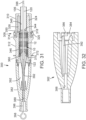
- FIG. 17 shows an enlarged view of the nose cone 122 secured to the distal end of the innermost shaft 120.
- the nose cone 122 in the illustrated embodiment includes a proximal end portion 174 that is sized to fit inside the distal end of the sheath 106.
- An intermediate section 176 of the nose cone 122 is positioned immediately adjacent the end of the sheath 106 in use and is formed with a plurality of longitudinal grooves, or recessed portions, 178.
- the diameter of the intermediate section 176 at its proximal end 180 desirably is slightly larger than the outer diameter of the sheath 106.
- the proximal end 180 can be held in close contact with the distal end of the sheath 106 to protect surrounding tissue from coming into contact with the metal edge of the sheath.
- FIG. 17B shows a cross-section the nose cone 122 and the sheath 106 in a delivery position with the prosthetic valve retained in a compressed delivery state inside the sheath 106 (for purposes of illustration, only the stent 12 of the prosthetic valve is shown).
- the proximal end 180 of the intermediate section 176 can abut the distal end of the sheath 106 and a tapered proximal surface 182 of the nose cone 122 can extend within a distal portion of the stent 12.
- the delivery apparatus 100 can include a valve-retaining mechanism 114 ( FIG. 8B ) for releasably retaining a stent 12 of a prosthetic valve.
- the valve-retaining mechanism 114 can include a first valve-securement component in the form of an outer fork 130 (as best shown in FIG. 12 ) (also referred to as an "outer trident” or “release trident”), and a second valve-securement component in the form of an inner fork 132 (as best shown in FIG. 17 ) (also referred to as an "inner trident” or “locking trident”).
- the outer fork 130 cooperates with the inner fork 132 to form a releasable connection with the retaining arms 30 of the stent 12.
- the proximal end of the outer fork 130 is connected to the distal segment 126 of the outer shaft 104 and the distal end of the outer fork is releasably connected to the stent 12.
- the outer fork 130 and the distal segment 126 can be integrally formed as a single component (e.g. , the outer fork and the distal segment can be laser cut or otherwise machined from a single piece of metal tubing), although these components can be separately formed and subsequently connected to each other.
- the inner fork 132 can be mounted on the nose catheter shaft 120 (as best shown in FIG. 17 ). The inner fork 132 connects the stent 12 to the distal end portion of the nose catheter shaft 120.
- the nose catheter shaft 120 can be moved axially relative to the outer shaft 104 to release the prosthetic valve 10 from the valve-retaining mechanism, as further described below.
- the outer fork 130 includes a plurality of angularly-spaced prongs 134 (three in the illustrated embodiment) corresponding to the retaining arms 30 of the stent 12, which prongs extend from the distal end of distal segment 126.
- the distal end portion of each prong 134 includes a respective opening 140.
- the inner fork 132 includes a plurality of angularly-spaced prongs 136 (three in the illustrated embodiment) corresponding to the retaining arms 30 of the stent 12, which prongs extend from a base portion 138 at the proximal end of the inner fork.
- the base portion 138 of the inner fork 132 is fixedly secured to the nose catheter shaft 120 ( e.g ., with a suitable adhesive) to prevent axial and rotational movement of the inner fork relative to the nose catheter shaft 120.
- each prong 134 of the outer fork 130 cooperates with a corresponding prong 136 of the inner fork 132 to form a releasable connection with a retaining arm 30 of the stent 12.
- the distal end portion of each prong 134 is formed with an opening 140.
- FIG. 42 also shows the prosthetic valve 10 secured to the delivery apparatus by the inner and outer forks before the prosthetic valve is loaded into the sheath 106. Retracting the inner prongs 136 proximally (in the direction of arrow 184 in FIG. 20 ) to remove the prongs from the openings 32 is effective to release the prosthetic valve 10 from the retaining mechanism.
- the inner fork 132 is moved to a proximal position ( FIG. 20 )
- the retaining arms 30 of the stent 12 can move radially outwardly from the openings 140 in the outer fork 130 under the resiliency of the stent.
- the valve-retaining mechanism 114 forms a releasable connection with the prosthetic valve 10 that is secure enough to retain the prosthetic valve relative to the delivery apparatus 100 to allow the user to fine tune or adjust the position of the prosthetic valve after it is deployed from the delivery sheath.
- the connection between the prosthetic valve and the retaining mechanism 114 can be released by retracting the nose catheter shaft 120 relative to the outer shaft 104 (which retracts the inner fork 132 relative to the outer fork 130).
- the delivery apparatus 100 can be inserted into the patient's body for delivery of the prosthetic valve.
- the prosthetic valve 10 can be delivered in a retrograde procedure where delivery apparatus is inserted into a femoral artery and advanced through the patient's vasculature to the heart.
- an introducer sheath can be inserted into the femoral artery followed by a guide wire, which is advanced through the patient's vasculature through the aorta and into the left ventricle.
- the delivery apparatus 100 can then be inserted through the introducer sheath and advanced over the guide wire until the distal end portion of the delivery apparatus containing the prosthetic valve 10 is advanced to a location adjacent to or within the native aortic valve.
- the prosthetic valve 10 can be deployed from the delivery apparatus 100 by rotating the torque shaft 110 relative to the outer shaft 104.
- the proximal end of the torque shaft 110 can be operatively connected to a manually rotatable handle portion or a motorized mechanism that allows the surgeon to effect rotation of the torque shaft 110 relative to the outer shaft 104.
- Rotation of the torque shaft 110 and the screw 112 causes the nut 150 and the sheath 106 to move in the proximal direction toward the outer shaft ( FIG. 22 ), which deploys the prosthetic valve 10 from the sheath 106.
- Rotation of the torque shaft 110 causes the sheath 106 to move relative to the prosthetic valve 10 in a precise and controlled manner as the prosthetic valve advances from the open distal end of the delivery sheath and begins to expand.
- the prosthetic valve 10 begins to advance from the delivery sheath 106 and expand, the prosthetic valve is held against uncontrolled movement from the sheath caused by the expansion force of the prosthetic valve against the distal end of the sheath.
- the prosthetic valve 10 is retained in a stationary position relative to the ends of the inner shaft 120 and the outer shaft 104 by virtue of the valve-retaining mechanism 114.
- the prosthetic valve 10 can be held stationary relative to the target location in the body as the sheath 106 is retracted. Moreover, after the prosthetic valve 10 is partially advanced from the sheath 106, it may be desirable to retract the prosthetic valve back into the sheath, for example, to reposition the prosthetic valve or to withdraw the prosthetic valve entirely from the body.
- the partially deployed prosthetic valve 10 can be retracted back into the sheath 106 by reversing the rotation of the torque shaft 110, which causes the sheath 106 to advance back over the prosthetic valve in the distal direction.
- the surgeon must apply push-pull forces to the shaft and/or the sheath to unsheathe the prosthetic valve. It is therefore difficult to transmit forces to the distal end of the device without distorting the shaft (e.g., compressing or stretching the shaft axially), which in turn causes uncontrolled movement of the prosthetic valve during the unsheathing process.
- the shaft and/or sheath can be made more rigid, which is undesirable because the device becomes harder to steer through the vasculature.
- the manner of unsheathing the prosthetic valve described above eliminates the application of push-pull forces on the shaft, as required in known devices, so that relatively high and accurate forces can be applied to the distal end of the shaft without compromising the flexibility of the device.
- the prosthetic valve 10 After the prosthetic valve 10 is advanced from the delivery sheath 106 and expands to its functional size (the expanded prosthetic valve 10 secured to the delivery apparatus is depicted in FIG. 42), the prosthetic valve remains connected to the delivery apparatus via the retaining mechanism 114. Consequently, after the prosthetic valve 10 is advanced from the delivery sheath 106, the surgeon can reposition the prosthetic valve relative to the desired implantation position in the native valve such as by moving the delivery apparatus in the proximal and distal directions or side to side, or rotating the delivery apparatus, which causes corresponding movement of the prosthetic valve.
- the retaining mechanism 114 desirably provides a connection between the prosthetic valve 10 and the delivery apparatus 100 that is secure and rigid enough to retain the position of the prosthetic valve relative to the delivery apparatus against the flow of the blood as the position of the prosthetic valve is adjusted relative to the desired implantation position in the native valve.
- the delivery apparatus 100 has at its distal end a semi-rigid segment comprised of relatively rigid components used to transform rotation of the torque shaft 110 into axial movement of the sheath 106.
- this semi-rigid segment in the illustrated embodiment is comprised of the prosthetic valve 10 and the screw 112.
- An advantage of the delivery apparatus 100 is that the overall length of the semi-rigid segment is minimized because the nut 150 is used rather than internal threads on the outer shaft to affect translation of the sheath 106.
- the reduced length of the semi-rigid segment increases the overall flexibility along the distal end portion of the delivery catheter.
- the length and location of the semi-rigid segment remains constant because the torque shaft 110 does not translate axially relative to the outer shaft 104.
- the curved shape of the delivery catheter can be maintained during valve deployment, which improves the stability of the deployment.
- a further benefit of the delivery apparatus 100 is that the ring 128 prevents the transfer of axial loads (compression and tension) to the section of the torque shaft 110 that is distal to the ring.
- the delivery apparatus 100 can be adapted to deliver a balloon-expandable prosthetic valve.
- the valve retaining mechanism 114 can be used to secure the prosthetic valve to the end of the delivery apparatus 100. Since the stent of the prosthetic valve is not self-expanding, the sheath 106 can be optional. The retaining mechanism 114 enhances the pushability of the delivery apparatus 100 and prosthetic valve assembly through an introducer sheath.
- FIGS. 23-26 illustrate the proximal end portion of the delivery apparatus 100, according to one embodiment.
- the delivery apparatus 100 can comprise a handle 202 that is configured to be releasably connectable to the proximal end portion of a catheter assembly 204 comprising catheters 102, 108, 118. It may be desirable to disconnect the handle 202 from the catheter assembly 204 for various reasons. For example, disconnecting the handle 202 can allow another device to be slid over the catheter assembly 204, such as a valve-retrieval device or a device to assist in steering the catheter assembly. It should be noted that any of the features of the handle 202 and the catheter assembly 204 can be implemented in any of the embodiments of the delivery apparatuses disclosed herein.
- FIGS. 23 and 24 show the proximal end portion of the catheter assembly 204 partially inserted into a distal opening of the handle 202.
- the proximal end portion of the main shaft 104 is formed with an annular groove 212 (as best shown in FIG. 24 ) that cooperates with a holding mechanism, or latch mechanism, 214 inside the handle.
- a holding mechanism or latch mechanism
- the opposite side of the holding mechanism 214 is contacted by a spring 220 that biases the holding mechanism to a position engaging the main shaft 104 at the groove 212.
- the engagement of the holding mechanism 214 within the groove 212 prevents axial separation of the catheter assembly from the handle 202.
- the catheter assembly 204 can be released from the handle 202 by depressing button 218, which moves the holding mechanism 214 from locking engagement with the main shaft 104.
- the main shaft 104 can be formed with a flat surface portion within the groove 212. The flat surface portion is positioned against a corresponding flat surface portion of the engaging portion 216. This engagement holds the main shaft 104 stationary relative to the torque shaft 110 as the torque shaft is rotated during valve deployment.
- the proximal end portion of the torque shaft 110 can have a driven nut 222 ( FIG. 26 ) that is slidably received in a drive cylinder 224 ( FIG. 25 ) mounted inside the handle 202.
- the nut 222 can be secured to the proximal end of the torque shaft 100 by securing the nut 222 over a coupling member 170 ( FIG. 15 ).
- FIG. 26 is a perspective view of the inside of the handle 202 with the drive cylinder 224 and other components removed to show the driven nut 222 and other components positioned within the drive cylinder.
- the cylinder 224 has a through opening (or lumen) extending the length of the cylinder that is shaped to correspond to the flats of the nut 222 such that rotation of the drive cylinder is effective to rotate the nut 222 and the torque shaft 110.
- the drive cylinder 224 can have an enlarged distal end portion 236 that can house one or more seals (e.g., O-rings 246) that form a seal with the outer surface of the main shaft 104 ( FIG. 25 ).
- the handle 202 can also house a fitting 238 that has a flush port in communication with the lumen of the torque shaft and/or the lumen of the main shaft 104.
- the drive cylinder 224 is operatively connected to an electric motor 226 through gears 228 and 230.
- the handle 202 can also house a battery compartment 232 that contains batteries for powering the motor 226.
- Rotation of the motor 226 in one direction causes the torque shaft 110 to rotate, which in turn causes the sheath 106 to retract and uncover a prosthetic valve at the distal end of the catheter assembly.
- Rotation of the motor 226 in the opposite direction causes the torque shaft 110 to rotate in an opposite direction, which causes the sheath 106 to move back over the prosthetic valve.
- An operator button 234 on the handle 202 allows a user to activate the motor, which can be rotated in either direction to un-sheath a prosthetic valve or retrieve an expanded or partially expanded prosthetic valve.
- the distal end portion of the nose catheter shaft 120 can be secured to an inner fork 132 that is moved relative to an outer fork 130 to release a prosthetic valve 10 secured to the end of the delivery apparatus 100.
- Movement of the shaft 120 relative to the main shaft 104 (which secures the outer fork 130) can be effected by a proximal end portion 240 of the handle 202 that is slidable relative to the main housing 244.
- the end portion 240 is operatively connected to the shaft 120 such that movement of the end portion 240 is effective to translate the shaft 120 axially relative to the main shaft 104 (causing a prosthetic valve 10 to be released from the inner 132 and outer 130 forks).
- the end portion 240 can have flexible side panels 242 on opposite sides of the handle 202 that are normally biased outwardly in a locked position to retain the end portion relative to the main housing 244.
- the user can depress the side panels 242, which disengage from corresponding features in the housing and allow the end portion 240 to be pulled proximally relative to the main housing, which causes corresponding axial movement of the shaft 120 relative to the main shaft 104.
- Proximal movement of the shaft 120 causes the prongs 136 of the inner fork 132 to disengage from the apertures 32 in the stent 12, which in turn allows the retaining arms 30 of the stent to deflect radially outwardly from the openings 140 in the prongs 134 of the outer fork 130, thereby releasing the prosthetic valve.
- FIG. 27 shows an alternative embodiment of a motor, indicated at 400, that can be used to drive a torque shaft (e.g ., torque shaft 110).
- a catheter assembly can be connected directly to one end of a shaft 402 of the motor, without gearing.
- the shaft 402 includes a lumen that allows for passage of an innermost shaft (e.g. , shaft 120) of the catheter assembly, a guide wire, and/or fluids for flushing the lumens of the catheter assembly.
- the power source for rotating the torque shaft 110 can be a hydraulic power source (e.g. , hydraulic pump) or pneumatic (air-operated) power source that is configured to rotate the torque shaft.
- the handle 202 can have a manually movable lever or wheel that is operable to rotate the torque shaft 110.
- a power source e.g ., an electric, hydraulic, or pneumatic power source
- a shaft which is turn is connected to a prosthetic valve 10.
- the power source is configured to reciprocate the shaft longitudinally in the distal direction relative to a valve sheath in a precise and controlled manner in order to advance the prosthetic valve from the sheath.
- the power source can be operatively connected to the sheath in order to reciprocate the sheath longitudinally in the proximal direction relative to the prosthetic valve to deploy the prosthetic valve from the sheath.
- FIGS. 30 and 31 present, respectively, an exploded view and a cross-sectional view of a valve storage assembly 300 that may be used in at least certain embodiments of the present disclosure for storing a prosthetic valve prior to use.
- the valve storage assembly 300 in the illustrated embodiment includes a storage tube assembly 308, a retaining tab 366, and a nose cone cap 382.
- the storage tube assembly 308 may be used to store the prosthetic valve 10, such as in a partially crimped state, until the valve 10 is ready to be implanted in a patient.
- the storage tube assembly 308 can include a proximal storage tube portion 310 and a distal storage tube portion 312.
- the proximal storage tube portion 310 can include locking tabs 314 that extend radially from opposing sides of an axially extending annular lip 316 formed at the distal end of the proximal storage tube portion 310.
- the proximal end of the distal storage tube portion 312 can define a circumferentially extending, annular recess 318 formed between an outer wall and an inner lip portion of the distal storage tube portion 312.
- the outer surface of the distal storage tube portion 312 can define slots 320 at opposing points, the slots providing an opening into the circumferential recess 318.
- the distal storage tube portion 312 can include an extension portion 324 configured to receive a cap portion 326.
- the cap portion 326 may include notches 328 to be received by mating ridges 330 formed in the surface of the extension portion 324.
- the cap portion 326 can further include a lip 332 extending from the notches 328 to the proximal end of the cap portion 326.
- the lip 332 can be configured to engage the upper surface 334 of the extension portion 324, which has a width smaller than the width of the cap portion 326 between the opposing sides of the lip 332.
- Opposing sides of the distal end of the distal storage tube portion 312 can include tab slots 336.
- a reduced diameter lip 338 extends from the distal end of the distal storage tube portion 312 and can include radially extending locking tabs 340.
- the cap portion 326 is secured to the extension portion 324.
- the proximal 310 and distal 312 storage tube portions are coupled to each other by inserting the lip 316 and tabs 314 of the proximal storage tube portion 310 into the corresponding recess 318 and slots 320 of the distal storage tube portion 312, as shown in FIG. 31 .
- the proximal storage tube portion 310 fits over the cap portion 326 and holds it in place on the extension portion 324.
- the sheath 106 can extend through the proximal end of the proximal portion 310 of the storage tube assembly 308.
- the inner surfaces of the extension portion 324 and the cap portion 326 of the distal storage tube portion 312 provide a tapered surface 344 extending from an inner bore 346 containing the valve 10 to a reduced diameter inner bore 348 housing the sheath 106.
- the tapered surface 344 helps guide and fully crimp the prosthetic valve 10 as it is pulled within the sheath 106.
- the opening of the bore 348 closest to the tapered surface 344 can be formed with an annular lip 350 that abuts the distal end of the sheath 106.
- the shaft 120 of the nose cone catheter 118 extends through the storage tube assembly 308 through an opening in the proximal end of the proximal storage tube portion 310.
- the nose cone 122 can include a distal, conical portion 354 that extends from the distal apex to a base 356.
- An intermediate nose cone portion 358 can extend proximally from the base 356.
- the diameter of the intermediate nose cone portion 358 can be smaller than the diameter of the distal portion 354 at its base 356.
- the proximal, annular surface of the base 356 extending about the intermediate nose cone portion 358 forms a shelf 360.
- the intermediate nose cone portion 358 has a constant diameter.
- the intermediate nose cone portion 358 is tapered, such as having a diameter that reduces towards the proximal end of the nose cone 122.
- the nose cone 122 can further include a tapered proximal section 362 that reduces in diameter, including compared with the diameter of the intermediate nose cone portion 358, towards the proximal end of the nose cone 122.
- the nose cone 122 is releasably retained in a fixed position relative to the storage tube assembly 308 using the retaining tab 366.
- the retaining tab 366 can include a tab body 368 having flat distal and proximal faces.
- One end portion of the tab body 368 comprises a pair of inner arms 370.
- the fixed ends of the inner arms 370 can form an arcuate surface at their juncture with an intermediate section of the tab body 368.
- the inner arms 370 may be in the form of a partial obround.
- the tab body 368 can further include a pair of arcuate outer arms 372 extending away from the intermediate section of the tab body 368.
- the inner arms 370 are disposed within the outer arms 372.
- the end portion of the tab body 368 opposite the arms can comprise a disk-shaped extension 376, which can define an aperture 378.
- the tab 366 is secured to the nose cone 122 by inserting the inner arms 370 of the tab 366 through the tab slots 336 of the distal storage tube portion 312 and about the intermediate portion 358 of the nose cone 122.
- the tab 366 may be placed such that the distal face of the tab 366 abuts the shelf 360 of the nose cone 122.
- the outer arms 372 of the tab 366 extend about and engage the outer radial surface of the distal tube portion 312.
- the outer arms 372 are sufficiently flexible to flex outwardly away from the inner arms 370, as the outer arms are forced over the outer surface of the distal tube portion 312.
- the outer arm 372 can be biased against the outer surface of the distal storage tube to assist in retaining the tab 366 in place until removed by the physician.
- the tab 366 is configured differently than shown in FIG. 30 .
- the tab 366 may lack the outer arms 372.
- the tab 366 may be retained in the proper position between the nose cone 122 and the frame 12 by other means.
- the inner arms 370 may be shaped or dimensioned to more securely engage the intermediate nose cone portion 358, such as by narrowing the gap between the inner arms 370.
- the tab 366 is maintained in position by compressing the tab 366 between the intermediate nose cone portion 358 and the frame 12 of the valve 10, such as by a nose cone cap 382 (described further below), which may be secured to the storage tube assembly 308.
- the tab 366 prevents movement of the nose cone catheter 118 (including its shaft 120) in the proximal direction relative to the prosthetic value 10 and the sheath 106 during shipping and subsequent handling by the physician in the operating room prior to insertion into a patient.
- the tab 366 also sets the distance between the distal end of the sheath 106 and the shelf 360 of the nose cone 122.
- the prosthetic valve 10 can, depending on the construction of the frame 12, expand lengthwise as it is compressed radially.
- the thickness of the tab 366 desirably is selected to accommodate lengthwise expansion of the frame 12 such that when the prosthetic valve 10 is fully loaded into the sheath 106, the distal end of the sheath 106 can abut the shelf 360 of the nose cone 122.
- the sheath 106 completely encloses the prosthetic valve 10 and protects against direct contact between the distal end of the frame 12 and surrounding tissue as the delivery apparatus is advanced through the patient's vasculature.
- saline or another liquid can be injected into the sheath 106.
- the sheath 106 can form a seal with the nose cone 122 sufficient to maintain the liquid in the sheath during the flushing step.
- the thickness of at least a portion of the tab 366, such as the inner arms 370 is between about 0.005 inches and about 0.1 inches, such as between about 0.010 inches and about 0.075 inches, or between about 0.02 inches and about 0.04 inches. In further implementations, the thickness is about 0.025 inches or about 0.031 inches, such as being 0.025 inches or 0.031 inches. In particular examples, a thickness being "about" a value means being the value or within 0.002 inches of the value, or being within a range of 10% higher or lower than the recited thickness.
- the valve storage assembly 300 further includes the nose cone cap 382.
- the nose cone cap 382 is generally conical in the illustrated embodiment, extending from a distal apex to a proximal base portion.
- a pair of arms 384 can extend from the base and can include slots 386 for receiving the locking tabs 340 of the proximal storage tube portion 312.
- an axial bore 388 extends through the interior of the nose cone cap 382, including through the distal apex.
- the interior of the nose cone cap 382 can include a plurality of axial fins 392 extending radially into the interior of the nose cone cap 382.
- the fins 392 are tapered at their proximal and distal ends such that, combined with the diameter of the nose cone cap 382 tapering toward its distal apex, the fins 392 define a conical cavity within the interior of the nose cone cap 382, the cavity having an apex towards the distal end of the nose cone cap 382.
- the fins 392 can extend slightly proximally beyond the proximal end of the nose cone cap 382, but not beyond the slots 386.
- the nose cone cap 382 prevents distal movement of the nose cone catheter 118 (including its shaft 120) relative to the prosthetic valve 10 and the sheath 106 during shipping and subsequent handling of the delivery apparatus 100 by the physician prior to insertion into a patient.
- a stylet 396 can be inserted through the distal end of the nose cone cap 382, through the nose cone 122 and the shaft 120 of the nose cone catheter 118.
- the stylet 396 can include a loop 398 at its distal end.
- the loop 398 is configured to have a diameter larger than the diameter of the opening of the axial bore 388 at the apex of the nose cone cap 382.
- the nose cone cap 382 may have other configurations.
- the nose cone cap 382 includes a latch releasably coupled to a tether (not shown).
- the tether is coupled to the nose cone cap 382, such as extending through one or more apertures (not shown) formed in the nose cone cap 382.
- a component of the tether or latch such as a pin, is configured to be inserted through the loop 398 of the stylet 396 and coupled to the tether. When coupled to the tether, the component, such as the pin, resists axial movement of the stylet 396.
- the nose cone cap 382 is placed over the nose cone 122 such that the distal portion 354 of the nose cone 122 is received in the conical cavity of the nose cone cap 382 formed by the fins 392.
- the slots 386 of the arms 384 are urged over the locking tabs 340 of the distal storage tube portion 312, such that the nose cone cap 382 is secured to the storage tube assembly 308, with the nose cone 122 being secured between, and relative to, the nose cone cap and the storage tube assembly.
- the stylet 396 is inserted through the apex of the nose cap 382, the nose cone 122, and the shaft 118.
- the stylet 396 serves to protect the components through which it passes from being damaged, and in particular the shaft 118, such as by compressive or bending forces experienced by the components during assembly and packaging of the delivery apparatus 100, and during subsequent handling of the delivery apparatus prior to insertion into a patient.
- an assembly that includes the delivery apparatus 100, the valve storage assembly 300, and the partially crimped prosthetic valve 10 (inside bore 346) can be packaged together in a sterile package enclosing all of these components.
- the package containing these components can be supplied to end users for storage and eventual use.
- the delivery apparatus 100, the partially crimped prosthetic valve 10, and the valve storage assembly 300 can be removed from the package while inside the operating room.
- the end user is ready to implant the valve 10
- the user may remove the nose cap 382 by releasing the locking tabs 340 from the slots 386.
- the user may then remove the tab 366 from engagement with the nose cone 122 and withdraw the tab 366 from the slot 336 in the distal storage tube portion 312.
- the prosthetic valve 10 can then be loaded into the sheath 106 and the stylet 396 can be removed from the delivery apparatus 100.
- FIGS. 33-35 present, respectively, an exploded view and cross-sectional views (taken through two different axes) of an alternative valve storage assembly 400 that may be used in at least certain embodiments of the present disclosure.
- the valve storage assembly 400 can include a storage tube assembly 408, a retaining tab 450, and a nose cone cap 458.
- the storage tube assembly 408 may be used to store the prosthetic valve 10, such as in a partially crimped state, until the valve 10 is ready to be implanted in a patient.
- the storage tube assembly 408 can include a proximal storage tube portion 410 and a distal storage tube portion 412.
- the proximal storage tube portion 410 can include locking tabs 414 that extend radially from an axially extending annular lip 416 formed at the distal end of the proximal storage tube portion 410.
- the proximal end of the proximal storage tube portion 410 can include a pair of radially extending wings 418.
- the wings 418 can be generally arcuate, such as generally semi-circular.
- the proximal end of the distal storage tube portion 412 can define upper and lower circumferential recesses 420, 422.
- the outer surface of the distal storage tube portion 412 can define slots 424 at opposing locations, the slots 424 providing openings into the circumferential recesses 420, 422.
- the upper and lower circumferential recesses 420, 422 can further define a pair of notches 426, where the recesses 420, 422 extend further towards the outer surface of the proximal end of the distal storage tube portion 412.
- the notches 426 can be slightly circumferentially offset with respect to the slots 424.
- the distal storage tube portion 412 can include an extension portion 428 configured to receive a cap portion 430.
- the cap portion 430 may include tabs 432 to be received by mating slots 434 formed in the surface of the extension portion 428.
- a reduced diameter lip 436 can extend axially from the distal end of the distal storage tube portion 412 and can include radially extending locking tabs 438.
- the cap portion 430 can be placed on the extension portion 428 by inserting the tabs 432 into the slots 434.
- the proximal 410 and distal 412 storage tube portions are coupled together by inserting the locking tabs 414 of the distal storage tube portion 412 through the notches 426, and then rotating the proximal storage tube portion 410 such that the locking tabs 414 engage the slots 424 of the distal tube portion 412.
- the wings 418 can assist the user in grasping, inserting, and twisting the proximal storage tube portion 410 during this assembly process.
- the proximal storage tube portion 410 fits over the cap portion 430 and holds it in place against the extension portion 428.
- the valve 10 is substantially retained within the bore 440 of the distal storage tube portion 412.
- the distal storage tube portion 412 can be sized such that the distal portion of the valve frame 12 extends slightly beyond the distal end of the distal storage tube portion 412.
- the sheath 106 extends through the proximal end 410 of the storage tube assembly 408.
- the inner surfaces of the extension portion 428 and the cap portion 430 of the distal storage tube portion 412 can include a tapered surface 442 extending from the inner bore 440 containing the valve 10 to a reduced diameter inner bore 444 housing the sheath 106.
- the tapered surface 442 helps guide and fully crimp the prosthetic valve 10 as it is pulled within the sheath 106 during preparation of the device for use.
- the opening of the bore 444 closest to the tapered surface 442 can be formed with an annular lip 446 that abuts the distal end of the sheath 106.
- the shaft 120 of the nose cone catheter 118 extends through the storage tube assembly 408 via an opening in the proximal end of the proximal storage tube portion 410.
- the nose cone 122 can be configured as described above with reference to FIGS. 30 and 31 .
- the nose cone 122 can be releasably retained in position using the retaining tab 450.
- the tab 450 can be generally configured in a similar manner as the tab 366 of FIGS. 30 and 31 .
- the tab 450 can include a gripping portion 452.
- the gripping portion 452 can be thicker than the legs 370, 372.
- the gripping portion 452 can be formed by overmolding a plastic material over an end portion of the tab body 368.
- the gripping portion 452 can include a plurality of ridges 454 formed on the faces of the gripping portion 452. As shown, the gripping portion 452 can have a triangular shape, with an apex at the proximal end of the gripping portion 452. However, in other implementations, the gripping portion 452 has a different shape, or includes features other than, or in addition to, the ridges 454 to facilitate gripping. For example, the gripping portion 452 may be formed from a material with a high coefficient of friction, or from a resilient material.
- the gripping portion 452 is formed from, or coated with, a colored material that helps attract attention to the gripping portion.
- the valve storage assembly 400 can further include the nose cone cap 458.
- the nose cone cap 458 can be generally conical, extending from a distal apex to a proximal base portion.
- a pair of arms 460 can extend axially from the base and can include slots 462 for receiving the locking tabs 438 of the proximal storage tube portion 412.
- a shorter tab arm 464 can extend axially from the base.
- the width of the tab arm 464 is configured such that the inner arms 370 of the tab 450 may be disposed about the radial sides of the tab arm 464.
- the side of the base opposite the tab arm 464 provides a recess for receiving the tab 450.
- the interior of the nose cone cap 458 include a plurality of axial fins 466 extending radially into the interior of the nose cone cap.
- the fins 466 are tapered at their proximal and distal ends such that, combined with the diameter of the nose cone cap 458 tapering toward its distal apex, the fins 466 define a conical cavity within the interior of the nose cone cap, the cavity having an apex towards the distal end of the nose cone cap.
- the proximal ends of the fins 466 taper radially inwardly moving distally toward the base of the nose cone cap 458.
- An inner bore 468 extends proximally from the apex of the conical cavity formed by the fins 466.
- a recess or groove 470 can be formed within the nose cone cap 458, about a distal portion of the inner bore 468.
- the inner bore 468 can be configured to receive a stylet 472.
- a curved distal end 474 of the stylet 472 can be received by the recess 470.
- the inner arms 370 of the tab 450 are inserted about the intermediate portion 358 of the nose cone 122.
- a proximal face of the tab 450 can abut the portion of the valve frame 12 extending beyond the distal storage tube portion 412.
- the stylet 472 can be inserted through the nose cone 122 and the shaft 120.
- the nose cone cap 458 can be placed over the stylet 472 and the nose cone 122, such that the stylet 472 is received by the recess 470 of the nose cone cap 458, and the nose cone 122 is received within the conical cavity formed by the fins 466.
- the locking tabs 438 of the distal storage tube portion 412 are urged into engagement with the slots 462 of the nose cone cap arms 460.
- the tab arm 464 is inserted through the inner arms 370 of the tab 450.
- the outer arms 372 of the tab 450 wrap around the outer surface of the nose cone cap 458, helping to secure the tab against inadvertent movement until a user desires to remove the tab.
- an assembly comprising the delivery apparatus 100, the valve storage assembly 400, and the partially crimped prosthetic valve 10 (inside bore 440) can be packaged together in a sterile package enclosing all of these components.
- the package containing these components can be supplied to end users for storage and eventual use.
- the delivery apparatus 100, the partially crimped prosthetic valve 10, and the valve storage assembly 400 can be removed from the package while inside the operating room.
- the user may remove the tab 450 from the nose cone 122 by grasping and pulling the gripping portion 452.
- the size and, optionally, color, or other features, of the tab 450 help remind the user to remove the tab 450 prior to using the delivery apparatus 100.
- the nose cone cap 458 may be removed by releasing the locking tabs 438 from the slots 462.
- the user may load the prosthetic valve 10 into the sheath 106 by rotating the torque shaft 110 in a direction to urge the sheath 106 against the annular lip 350, 446, which causes the prosthetic valve 10 to slide into the sheath 106 (as best shown in FIG. 17B ).
- the torque shaft 110 can be rotated by actuating the motor of the handle.
- the storage tube assembly 308, 408 can be removed from the delivery apparatus 100, which is now ready for insertion into the patient.
- storing the prosthetic valve 10 in a partially crimped state inside the storage tube assembly eliminates the task of connecting the prosthetic valve to the delivery apparatus and greatly simplifies the crimping process for the surgeon.
- the leaflets 34 of the prosthetic valve are treated during the manufacturing process so that they are completely or substantially dehydrated and can be stored in a partially or fully crimped state without a hydrating fluid.
- the package containing the prosthetic valve and the delivery apparatus can be free of any liquid.
- Methods for treating tissue leaflets for dry storage are disclosed in U.S. Patent No. 8,007,992 and U.S. Patent Publication No. 2009/0164005, filed December 18, 2008 .
- additional details regarding the loading of the valve 10 within a storage tube are described in U.S. Patent Publication No. 2012/0239142 (Application No. 13/405,119), filed February 24, 2012 .
- FIG. 37 illustrates a valve storage assembly 500 that may be used to help maintain the nose cone 122 in a fixed axial position relative to the prosthetic valve 10 and the other components of the delivery apparatus 100.
- the valve storage assembly 500 can include a nose cone cap 506 and a storage tube assembly 508.
- the nose cone cap 506 is releasably secured to the storage tube assembly 508, such as through the use of slots and mating locking tabs, as described above.
- the nose cone 122 is at least partially disposed inside the nose cone cap 506, and the elongated shaft 120 of the nose cone catheter 118 extends proximally through the storage tube assembly 508.
- a stylet 514 can be inserted into the nose cone cap 506 through an opening in the distal end of the nose cone cap 506.
- the stylet 514 can include a loop 516 at its distal end, a distal straight portion 518, a curved portion 520, and a proximal straight portion 522.
- the curved portion 520 can include at least one bend.
- the stylet 514 is shown with distal 518 and proximal 522 straight portions, in further implementations, the distal 518, proximal 522, or both distal 518 and proximal 522 straight portions are omitted from the stylet 514. That is, the curved portion 520 may be extended to take the place of the distal 518 or proximal 522 straight portions.
- the incorporation of a bend in the curved portion 520 helps engage the stylet 514 with the lumen of the component in which the curved portion is located, such as to reduce undesired axial movement of the nose cone catheter 118.
- the effective width or diameter of the curved portion 520 is slightly greater than the inner diameter of the lumen through which it extends to create an interference fit between the lumen and the curved portion.
- the curved portion 520 is shown as located within the nose cone 122, the curved portion 520 could be located in a different component, or in additional components, such as in order to provide a desired degree of resistance to proximal axial movement of the nose cone catheter 118.
- the curved section 520 can extend into the lumen of shaft 120.
- parameters such as the number of bends in the curved portion, the width of the bends (and thus the effective diameter of the stylet in the curved portion), the degree of curvature of the bends, and the relative lengths of the distal 518 and proximal 522 straight portions can be adjusted to provide a desired degree of resistance.
- wider bends, sharper curvatures, and longer curved portions 520 will produce increased resistance to removal of the stylet 514 from the lumen through which it is inserted.
- the amplitude or width of the bends in the curved portion 520 creates an effective diameter in the curved portion that is between about 5% and about 50% larger than the lumen through which the curved portion extends, such as between about 10% and about 40% larger, or between about 10% and about 30% larger.
- FIGS. 38A and 38B illustrate an alternative implementation 600 of a valve-retaining mechanism.
- the valve-retaining mechanism 600 can be generally configured as described with reference to FIGS. 8B , 12 , 19, and 20 , for example.
- the prongs 606 of an inner fork (not shown in FIGS. 37A and 38B , but analogous to the inner fork 132 of FIG. 17 ) incorporate a bend 614.
- the bend 614 causes the distal end portions of the prongs 606 to be directed radially inwardly towards the shaft 120.
- the proximal ends of the retaining arms 30 of the frame 12 pass through the openings 140 in the distal ends of the prongs 134 of the outer fork 130, the prongs 606 extend adjacent the prongs 134 and then pass distally through the openings 32 of the retaining arms 30 of the frame 12 and then bend radially inwardly.
- the prongs 606 are biased between the proximal ends of the retaining arms 30 and the portion of the prongs 134 of the outer fork 130 adjacent the proximal ends of the apertures 140.
- incorporating the bends 614 into the prongs 606 helps maintain the relative positions of the prongs 606, prongs 134, and retaining arms 30 when then valve-retaining mechanism 600 is in the locked configuration, helping to prevent or reduce axial movement of these components. Because the prongs 606, the inner fork 132, and the nose cone 122 are coupled to the shaft 120 of the nose-cone catheter 118, this resistance to axial movement also helps maintain the position of the nose cone 122 relative to the distal end of the frame 12 and the other components of the delivery apparatus.
- the angle of the bends 614 is typically selected to provide a desired degree of resistance to axial movement of the prongs 136 relative to the apertures 32 and the outer fork 130. Sharper bends 614 may help secure the valve-retaining mechanism 600 in the locked configuration. However, it also can result in a user having to apply a greater force to the inner fork 132 when the user desires to remove the prongs 606 from engagement with the apertures 32, causing the frame 12 to be released from the prongs 134 of the outer fork 130.
- the bends 614 can be formed in the prongs 606 using any suitable method.
- the prongs 606 may be cut, such as by laser cutting, to incorporate the desired bend 614 at the appropriate location.
- the prongs 606 are bent, such as about a transverse axis, for example, an axis parallel to the width of the prongs 606, or an axis normal to the width.
- the prongs 606 are constructed from a shape memory material, such as nitanol.
- the bends 614 can be formed in the desired shape by heat-setting the prongs 606.
- the curve radius is between about 0.025 inches to about 0.75 inches, such as between about 0.05 inches and about 0.5 inches, or between about 0.1 inches and about 0.5 inches.
- the distance between the axis of the unbent portion of the prongs 136, and the infection point at the apex of the bend is between about 75% and 400% of the width of the prong 606, such as being between about the width of the prong 606 and about three times the width of the prong 606.
- the distance over which the bend 614 occurs can also affect the resistance provided by the bend 614.
- a bend 614 occurring over a shorter distance will typically create more resistance than a bend of equivalent severity occurring over a longer distance.
- the bend 614 occurs over a distance of between about 5% and about 75% of the length of the prong 606, such as between about 10% and about 60%, or between about 20% and about 50%.
- the bend 614 may also have different shapes.
- the bend 614 has linear sides, such as being triangular or square.
- the sides of the bend 614 are arcuate, such as having a parabolic shape.
- bends 614 with arcuate sides provide less resistance to movement of the prongs 134 and the apertures 32 than bends 614 with linear sides.
- the term “and/or” used between the last two of a list of elements means any one or more of the listed elements.
- the phrase “A, B, and/or C” means “A,” “B,” “C,” “A and B,” “A and C,” “B and C” or "A, B and C.”
- Coupled generally means physically coupled or linked and does not exclude the presence of intermediate elements between the coupled items absent specific contrary language.
Abstract
Description
- The present disclosure relates to methods for maintaining the position of a nose cone relative to the frame of a prosthetic valve (e.g., prosthetic heart valve) in a delivery apparatus for implanting the prosthetic valve, and apparatus for carrying out such methods.
- Prosthetic cardiac valves have been used for many years to treat cardiac valvular disorders. The native heart valves (such as the aortic, pulmonary, and mitral valves) serve critical functions in assuring the forward flow of an adequate supply of blood through the cardiovascular system. These heart valves can be rendered less effective by congenital, inflammatory, or infectious conditions. Such damage to the valves can result in serious cardiovascular compromise or death. For many years the definitive treatment for such disorders was the surgical repair or replacement of the valve during open heart surgery, but such surgeries are prone to many complications. More recently a transvascular technique has been developed for introducing and implanting a prosthetic heart valve using a flexible catheter in a manner that is less invasive than open heart surgery.
- In this technique, a prosthetic valve is mounted in a crimped state on the end portion of a flexible catheter and advanced through a blood vessel of the patient until the prosthetic valve reaches the implantation site. The prosthetic valve at the catheter tip is then expanded to its functional size at the site of the defective native valve, such as by inflating a balloon on which the prosthetic valve is mounted. Alternatively, the prosthetic valve can have a resilient, self-expanding stent or frame that expands the prosthetic valve to its functional size when it is advanced from a delivery sheath at the distal end of the catheter.
- A nose cone is typically located at the distal end of the catheter, providing for atraumatic tracking of the catheter and its associated components through the patient's vasculature. The nose cone is desirably positioned proximate the frame supporting the valve. If the nose cone is not positioned properly with respect to the frame, gaps or exposed frame edges may cause injury to the patient, or otherwise interfere with valve delivery. The position of the nose cone can typically vary from its initial position, such as during manufacturing, shipping, storage, or preparation of a device that includes the nose cone and frame.
- Certain embodiments of the present disclosure provide a prosthetic valve delivery assembly that includes a storage tube. The assembly includes a prosthetic heart valve that includes a frame having a distal portion and a proximal portion. The valve is at least partially disposed within the storage tube, such as being disposed in the storage tube or at least substantially disposed within the storage tube. The assembly further includes a nose cone having a proximal end and a distal end and disposed about an elongated shaft that extends through the storage tube. A removable tab is disposed between the distal frame portion and the nose cone. The tab assists in maintaining the position of the nose cone relative to the distal end of the frame.
- In a particular implementation, the tab includes a proximal portion configured to be grasped by a user and a distal portion configured to be inserted about the proximal end of the nose cone. The distal portion defines a pair of arms. The arms engage the proximal end of the nose cone. For example, the nose cone may include a distal, conical, portion extending from a distal apex to a base and an intermediate portion extending proximally from the base. The diameter of the intermediate portion proximate the base is smaller than a diameter of the base of the distal portion of the nose cone. The arms are disposed about the intermediate portion of the nose cone.
- In another implementation, the storage tube has an outer surface that defines a radial slot configured to receive the arms of the tab. In a particular example, the storage tube includes a pair of slots in opposing sides of the storage tube, such that the arms can be inserted through a first slot and out of a second slot. According to another example, the valve is positioned proximally relative to the slot, such that the tab arms restrain the valve against distal movement when the tab arms are inserted through the slot.
- According to another aspect, the distal end of the frame extends beyond the distal end of the storage tube. The nose cone is positioned such that a proximal face of the tab abuts the frame when the arms are inserted about the proximal end of the nose cone.
- According to another embodiment, the present disclosure provides a tab, including a tab that may be used with the prosthetic valve delivery assembly described above. The tab includes a pair of outer arms extending about a pair of inner arms. The outer arms engage an outer surface of the assembly. In a particular example, the outer arms extend radially about, and engage, an outer surface of the storage tube. In another example, the assembly includes a nose cone cap that engages the distal end of the nose cone. The outer arms extend radially about, and engage, the outer surface of the nose cone cap.
- According to another embodiment of a tab, including a tab that may be used with the prosthetic valve delivery assembly described above, the tab includes a pair of arms located at a distal end of the tab and configured to be inserted about a nose cone. A proximal portion of the tab defines a gripping surface that is configured to assist a user in gripping the tab. In one example, the gripping surface is thicker than the distal portion of the tab. The tab may include additional features to assist gripability, such as one or more embossed ridges. According to another example, the gripping surface is configured to indicate to a user that the tab should be removed, such as having a triangular shape with a distal apex. The gripping surface may also be formed with other visual indications to draw attention to the tab, such as forming it from, or coating it with, a brightly colored material.
- The present disclosure also provides a nose cone cap, which may be used in the above-described prosthetic valve delivery assembly. The nose cone cap extends over at least a distal portion of the nose cone and is releasably coupled to a distal end of a storage tube. In some implementations, the nose cone cap is generally conical and includes a distal apex and a proximal base. In particular implementations, the base includes at least one proximally extending arm comprising a locking mechanism to engage a mating locking mechanism on the storage tube of the prosthetic valve delivery assembly. For example, the nose cone cap and storage tube may include mating slots and tabs.
- In further implementations, the nose cone cap is configured to receive the tab, such as arms of the tab. In a particular example, the nose cone cap can include a tab arm extending proximally from the base of the nose cone cap. The tab arm is dimensioned such that the tab arms extend about the lateral sides of the nose cone cap tab arm. In a more particular example, the nose cone cap, at the side opposite the tab arm, includes an aperture for receiving the tab. For example, the base may define a recess at the proximal end of the base.
- In yet another implementation, the interior of the nose cone cap includes a plurality of axially and radially extending fins defining a cavity for receiving at least a distal end portion of a nose cone. In at least certain examples, the fins are tapered, such that a cavity formed by the fins is larger at the base of those cone cap than at a distal portion of the nose cone cap.
- The fins may be configured, for example, to define a cavity dimensioned to receive a proximal portion of the nose cone. When the nose cone cap is coupled to the storage tube, the fins help limit distal movement of the nose cone relative to the storage tube.
- In particular implementations, the nose cone cap is configured to be used with a valve delivery assembly that includes a stylet. In one example, such as a nose cone cap that includes internal fins, the nose cone cap defines an internal recess configured to receive a distal end of the stylet. For example, the recess may receive a loop located at the distal end of the stylet. The stylet is positioned between the fins as it extends proximally through the nose cone cap.
- In another example, the nose cone cap includes an axial bore for receiving the stylet. The bore may be dimensioned such that it has a smaller diameter than a distal loop of the stylet. Thus, the stylet is prevented from moving axially past the apex of the nose cone cap. In a particular example, the stylet is configured to be insertable proximally through the apex of the nose cone cap until the loop of the stylet abuts the apex of the nose cone cap.
- In a further example, the nose cone cap includes a latch releasably coupled to a tether. The tether is coupled to the nose cone cap, such as extending through one or more apertures formed in the nose cone cap. A component of the latch or tether, such as a pin, is configured to be inserted through a loop located at the distal end of the stylet and coupled to the tether. When coupled to the tether, the latch and tether resist axial movement of the stylet.
- In further embodiments, the present disclosure provides a method for securing the position of a nose cone relative to a prosthetic valve. A prosthetic valve is placed at least partially within a storage tube. A nose cone is positioned relative to the valve. A tab is inserted between at least a portion of the nose cone and the valve such that the nose cone is restrained from proximal movement relative to the tab. The tab, in one implementation, is inserted through a radially extending slot formed in an outer surface of the storage tube. In another implementation, the valve extends distally from the distal end of the storage tube and the tab is inserted such that it abuts the distal end of the valve.
- In a particular implementation, the method includes placing a nose cone cap over a distal end portion of the nose cone and securing the nose cone cap to the storage tube. The nose cone is thus restrained by the nose cone cap from distal and/or proximal axial movement relative to the storage tube. In a particular example, the nose cone cap comprises internal fins and the nose cone is received in a cavity formed by the fins. The fins compress a distal portion of the nose cone proximally against the tab. In a further example, a stylet is inserted through the nose cone and the nose cone cap is inserted over the stylet. In one aspect, the stylet includes a loop at its distal end, and the loop is received by a recess formed in the nose cone cap. In another example, the stylet is inserted proximally through a distal apex of the nose cone cap into an axial bore, wherein the axial bore has a diameter smaller than the diameter of a loop located at the distal end of the stylet. In a further example, a tether is inserted through the loop of the stylet and releasably coupled to a latch, wherein the tether is further secured to the nose cone. The latch and tether provide resistance against axial movement of the stylet.
- The method, in further implementations, includes inserting tab arms about an exterior surface of a prosthetic valve delivery assembly. In one example, the arms are inserted about an exterior surface of the storage tube. In another example, the arms are inserted about an exterior surface of a nose cone cap coupled to the storage tube.
- In another embodiment, the present disclosure provides a prosthetic valve delivery assembly that includes a stylet, a nose cone coupled to an elongated shaft, and a prosthetic heart valve disposed about the elongated shaft. The stylet inserted through a lumen of the nose cone and a lumen of the elongated shaft. The stylet includes at least one bend that is located in, and engages, at least one of the nose cone lumen and the elongated shaft lumen. In various examples, the stylet bend is located in the nose cone lumen, the elongated shaft lumen, or both the elongated shaft and nose cone lumens. In at least one implementation, the stylet includes a plurality of bends.
- In another embodiment, the present disclosure provides a valve-retention assembly useable with a prosthetic heart valve delivery assembly. The valve-retention assembly includes a release member that includes at least one release prong defining an aperture proximate a distal end of the release prong, a locking member that includes at least one locking arm, and a prosthetic heart valve that includes a frame having at least one aperture formed in a proximal retaining arm of the frame and configured to be inserted through the aperture of the release prong. The locking member is coupled to an elongated shaft that includes a nose cone. The locking arm defines a bend at a distal portion of the locking arm. The valve retaining arm is inserted through the aperture of the release prong. The locking arm is inserted through the aperture of the valve retaining arm, such that a portion of the valve retaining arm proximate the aperture of the valve retaining arm is received in the bend of the locking arm, thus providing resistance to longitudinal movement of the valve.
- There are additional features and advantages of the various embodiments of the present disclosure. They will become evident from the following disclosure.
- In this regard, it is to be understood that this is a summary of the various embodiments described herein. Any given embodiment of the present disclosure need not provide all features noted above, nor must it solve all problems or address all issues in the prior art noted above.
- Various embodiments are shown and described in connection with the following drawings in which:
-
FIG. 1 is a perspective view of a prosthetic valve that can be used to replace the native aortic valve of the heart, according to one embodiment. -
FIG. 2 is a perspective view of a portion of the prosthetic valve ofFIG. 1 illustrating the connection of two leaflets to the support frame of the prosthetic valve. -
FIG. 3 is side elevation view of the support frame of the prosthetic valve ofFIG. 1 . -
FIG. 4 is a perspective view of the support frame of the prosthetic valve ofFIG. 1 . -
FIG. 5A is a cross-sectional view of the heart showing the prosthetic valve ofFIG. 1 implanted within the aortic annulus. -
FIG. 5B is an enlarged view ofFIG. 5A illustrating the prosthetic valve implanted within the aortic annulus, shown with the leaflet structure of the prosthetic valve removed for clarity. -
FIG. 6 is a perspective view of the leaflet structure of the prosthetic valve ofFIG. 1 shown prior to being secured to the support frame. -
FIG. 7 is a cross-sectional view of the prosthetic valve ofFIG. 1 . -
FIG. 8 is a cross-sectional view of an embodiment of a delivery apparatus that can be used to deliver and implant a prosthetic valve, such as the prosthetic valve shown inFIG. 1 .FIGS. 8A-8C are enlarged cross-sectional views of sections ofFIG. 8 . -
FIG. 9 is an exploded view of the delivery apparatus ofFIG. 8 . -
FIG. 10 is a side view of the guide catheter of the delivery apparatus ofFIG. 8 . -
FIG. 11 is a perspective, exploded view of the proximal end portion of the guide catheter ofFIG. 10 . -
FIG. 12 is a perspective, exploded view of the distal end portion of the guide catheter ofFIG. 10 . -
FIG. 13 is a side view of the torque shaft catheter of the delivery apparatus ofFIG. 8 . -
FIG. 14 is an enlarged side view of the rotatable screw of the torque shaft catheter ofFIG. 13 . -
FIG. 15 is an enlarged perspective view of a coupling member disposed at the end of the torque shaft. -
FIG. 16 is an enlarged perspective view of the threaded nut used in the torque shaft catheter ofFIG. 13 . -
FIG. 17 is an enlarged side view of the distal end portion of the nose cone catheter of the delivery apparatus ofFIG. 8 . -
FIG. 17A is an enlarged, cross-sectional view of the nose cone of the catheter shownFIG. 17 . -
FIG. 17B is an enlarged cross-sectional view of the distal end portion of the delivery apparatus ofFIG. 8 showing the stent of a prosthetic valve retained in a compressed state within a delivery sheath. -
FIG. 18 is an enlarged side view of the distal end portion of the delivery apparatus ofFIG. 8 showing the delivery sheath in a delivery position covering a prosthetic valve in a compressed state for delivery into a patient. -
FIG. 19 is an enlarged cross-sectional view of a section of the distal end portion of the delivery apparatus ofFIG. 8 showing the valve-retaining mechanism securing the stent of a prosthetic valve to the delivery apparatus. -
FIG. 20 is an enlarged cross-sectional view similar toFIG. 19 , showing the inner fork of the valve-retaining mechanism in a release position for releasing the prosthetic valve from the delivery apparatus. -
FIGS. 21 and 22 are enlarged side views of the distal end portion of the delivery apparatus ofFIG. 8 , illustrating the operation of the torque shaft for deploying a prosthetic valve from a delivery sheath. -
FIGS. 23-26 are various views of an embodiment of a motorized delivery apparatus that can be used to operate the torque shaft of the delivery apparatus shown inFIG. 8 . -
FIG. 27 is a perspective view of an alternative motor that can be used to operate the torque shaft of the delivery apparatus shown inFIG. 8 . -
FIG. 28A is an enlarged view of a distal segment of the guide catheter shaft ofFIG. 10 . -
FIG. 28B shows the cut pattern for forming the portion of the shaft shown inFIG. 28A , such as by laser cutting a metal tube. -
FIG. 29A is an enlarged view of a distal segment of a guide catheter shaft, according to another embodiment. -
FIG. 29B shows the cut pattern for forming the shaft ofFIG. 29A , such as by laser cutting a metal tube. -
FIG. 30 is an exploded view of a valve storage assembly useable with the delivery apparatus ofFIG. 8 . -
FIG. 31 is an enlarged cross-sectional view of the valve storage assembly ofFIG. 30 . -
FIG. 32 is an enlarged cross-sectional view of a nose cone cap useable with the valve storage assembly ofFIGS. 30 and31 . -
FIG. 33 is an exploded view of another implementation of a valve storage assembly useable with the delivery apparatus ofFIG. 8 . -
FIG. 34 is an enlarged cross-sectional view of the valve storage assembly ofFIG. 32 , taken through the longitudinal axis of the tab. -
FIG. 35 is an enlarged cross-sectional view of the valve storage assembly ofFIG. 32 , taken through a transverse axis of the tab. -
FIG. 36 is an enlarged cross-sectional view of a nose cone cap useable with the valve storage assembly ofFIGS. 33-35 . -
FIG. 37 is a cross-sectional view of an alternative valve storage assembly useable with the delivery assembly ofFIG. 8 , having a stylet incorporating one or more bends. -
FIG. 38A is a side view of a valve-retaining mechanism useable with the delivery apparatus ofFIG. 8 , showing the components in a disengaged state. -
FIG. 38B is a side view of the valve-retaining mechanism ofFIG. 38A , showing the components in a locked configuration. - Referring first to
FIG. 1 , there is shown a prostheticaortic heart valve 10, according to one embodiment. Theprosthetic valve 10 includes an expandable frame member, or stent, 12 that supports aflexible leaflet section 14. Theprosthetic valve 10 is radially compressible to a compressed state for delivery through the body to a deployment site and expandable to its functional size shown inFIG. 1 at the deployment site. In certain embodiments, theprosthetic valve 10 is self-expanding; that is, the prosthetic valve can radially expand to its functional size when advanced from the distal end of a delivery sheath. Apparatuses particularly suited for percutaneous delivery and implantation of a self-expanding prosthetic valve are described in detail below. In other embodiments, the prosthetic valve can be a balloon-expandable prosthetic valve that can be adapted to be mounted in a compressed state on the balloon of a delivery catheter. The prosthetic valve can be expanded to its functional size at a deployment site by inflating the balloon, as known in the art. - The illustrated
prosthetic valve 10 is adapted to be deployed in the native aortic annulus, although it also can be used to replace the other native valves of the heart. Moreover, theprosthetic valve 10 can be adapted to replace other valves within the body, such venous valves. -
FIGS. 3 and 4 show thestent 12 without theleaflet section 14 for purposes of illustration. As shown, thestent 12 can be formed from a plurality of longitudinally extending, generally sinusoidal shaped frame members, or struts, 16. Thestruts 16 are formed with alternating bends and are welded or otherwise secured to each other atnodes 18 formed from the vertices of adjacent bends so as to form a mesh structure. Thestruts 16 can be made of a suitable shape memory material, such as the nickel titanium alloy known as Nitinol, that allows the prosthetic valve to be compressed to a reduced diameter for delivery in a delivery apparatus (such as described below) and then causes the prosthetic valve to expand to its functional size inside the patient's body when deployed from the delivery apparatus. If the prosthetic valve is a balloon-expandable prosthetic valve that is adapted to be crimped onto an inflatable balloon of a delivery apparatus and expanded to its functional size by inflation of the balloon, thestent 12 can be made of a suitable ductile material, such as stainless steel. - The
stent 12 has aninflow end 26 and anoutflow end 27. The mesh structure formed bystruts 16 comprises a generally cylindrical "upper" oroutflow end portion 20, an outwardly bowed or distendedintermediate section 22, and an inwardly bowed "lower" orinflow end portion 24. Theintermediate section 22 desirably is sized and shaped to extend into the Valsalva sinuses in the root of the aorta to assist in anchoring the prosthetic valve in place once implanted. As shown, the mesh structure desirably has a curved shape along its entire length that gradually increases in diameter from theoutflow end portion 20 to theintermediate section 22, then gradually decreases in diameter from theintermediate section 22 to a location on theinflow end portion 24, and then gradually increases in diameter to form a flared portion terminating at theinflow end 26. - When the
prosthetic valve 10 is in its expanded state, theintermediate section 22 has a diameter D1, theinflow end portion 24 has a minimum diameter D2, theinflow end 26 has a diameter D3, and theoutflow end portion 20 has a diameter D4, where D2 is less than D1 and D3, and D4 is less than D2. In addition, D1 and D3 desirably are greater than the diameter of the native annulus in which the prosthetic valve is to be implanted. In this manner, the overall shape of thestent 12 assists in retaining the prosthetic valve at the implantation site. - More specifically, and referring to
FIGS. 5A and5B , theprosthetic valve 10 can be implanted within a native valve (the aortic valve in the illustrated example) such that thelower section 24 is positioned within theaortic annulus 28, theintermediate section 22 extends above the aortic annulus into the Valsalva'ssinuses 56, and the lower flaredend 26 extends below the aortic annulus. Theprosthetic valve 10 is retained within the native valve by the radial outward force of thelower section 26 against the surrounding tissue of theaortic annulus 28 as well as the geometry of thestent 12. Specifically, theintermediate section 22 and the flaredlower end 26 extend radially outwardly beyond theaortic annulus 28 to better resist against axial dislodgement of theprosthetic valve 10 in the upstream and downstream directions (toward and away from the aorta). Depending on the condition of thenative leaflets 58, theprosthetic valve 10 typically is deployed within thenative annulus 28 with thenative leaflets 58 folded upwardly and compressed between the outer surface of thestent 12 and the walls of theValsalva sinuses 56, as depicted inFIG. 5B . In some cases, it may be desirable to excise theleaflets 58 prior to implanting theprosthetic valve 10. - Known prosthetic valves having a self-expanding frame typically have additional anchoring devices or frame portions that extend into and become fixed to non-diseased areas of the vasculature. Because the shape of the
stent 12 assists in retaining the prosthetic valve, additional anchoring devices are not required and the overall length L of the stent can be minimized to prevent the stentupper portion 20 from extending into the non-diseased area of the aorta, or to at least minimize the extent to which theupper portion 20 extends into the non-diseased area of the aorta. Avoiding the non-diseased area of the patient's vasculature helps avoid complications if future intervention is required. For example, the prosthetic valve can be more easily removed from the patient because the stent is primarily anchored to the diseased part of the native valve. Furthermore, a shorter prosthetic valve is more easily navigated around the aortic arch. - In particular embodiments, for a prosthetic valve intended for use in a 22-mm to 24-mm annulus, the diameter D1 is about 28 mm to about 32 mm, with 30 mm being a specific example; the diameter D2 is about 24 mm to about 28 mm, with 26 mm being a specific example; the diameter D3 is about 28 mm to about 32 mm, with 30 mm being a specific example; and the diameter D4 is about 24 mm to about 28 mm, with 26 mm being a specific example. The length L in particular embodiments is about 20 mm to about 24 mm, with 22 mm being a specific example.
- Referring again to
FIG. 1 , thestent 12 can have a plurality of angularly spaced retaining arms, or projections, in the form of posts 30 (three in the illustrated embodiment) that extend from the stentupper portion 20. Each retainingarm 30 has arespective aperture 32 that is sized to receive prongs of a valve-retaining mechanism that can be used to form a releasable connection between the prosthetic valve and a delivery apparatus (described below). In alternative embodiments, the retainingarms 30 need not be provided if a valve-retaining mechanism is not used. - As best shown in
FIGS. 6 and 7 , theleaflet assembly 14 in the illustrated embodiment comprises threeleaflets inflow end portion 60 and anoutflow end portion 62. The leaflets can comprise any suitable biological material (e.g., pericardial tissue, such as bovine or equine pericadium), bio-compatible synthetic materials, or other such materials, such as those described inU.S. Patent No. 6,730,118 . Theleaflet assembly 14 can include an annular reinforcingskirt 42 that is secured to the outer surfaces of the inflow end portions of theleaflets suture line 44 adjacent the inflow end of the prosthetic valve. The inflow end portion of theleaflet assembly 14 can be secured to thestent 12 by suturing theskirt 42 to struts 16 of thelower section 24 of the stent (best shown inFIG. 3 ). As shown inFIG. 7 , theleaflet assembly 14 can further include an inner reinforcingstrip 46 that is secured to the inner surfaces of theinflow end portions 60 of the leaflets. - Referring again to
FIGS. 1 and 2 , the outflow end portion of theleaflet assembly 14 can be secured to the upper portion of thestent 12 at three angularly spaced commissure attachments of theleaflets FIG. 2 , each commissure attachment can be formed by wrapping a reinforcingsection 36 around adjacentupper edge portions 38 of a pair of leaflets at the commissure formed by the two leaflets and securing the reinforcingsection 36 to theedge portions 38 withsutures 48. The sandwiched layers of the reinforcing material and leaflets can then be secured to thestruts 16 of thestent 12 with sutures 50 adjacent theoutflow end 27 of the stent. The leaflets therefore desirably extend the entire length or substantially the entire length of thestent 12 from theinflow end 26 to theoutflow end 27. The reinforcingsections 36 reinforce the attachment of the leaflets to thestent 12 so as to minimize stress concentrations at the suture lines and avoid "needle holes" on the portions of the leaflets that flex during use. The reinforcingsections 36, theskirt 42, and the inner reinforcingstrip 46 desirably are made of a bio-compatible synthetic material, such as polytetrafluoroethylene (PTFE), or a woven fabric material, such as woven polyester (e.g., polyethylene terephtalate (PET)). -
FIG. 7 shows the operation of theprosthetic valve 10. During diastole, theleaflets intermediate section 22 of thestent 12 defines a space between the intermediate section and the leaflets that mimics the Valsalva sinuses. Thus, when the leaflets close, backflow entering the "sinuses" creates a turbulent flow of blood along the upper surfaces of the leaflets, as indicated byarrows 52. This turbulence assists in washing the leaflets and theskirt 42 to minimize clot formation. - The
prosthetic valve 10 can be implanted in a retrograde approach where the prosthetic valve, mounted in a crimped state at the distal end of a delivery apparatus, is introduced into the body via the femoral artery and advanced through the aortic arch to the heart, as further described inU.S. Patent Publication No. 2008/0065011 . -
FIGS. 8 and 9 show adelivery apparatus 100, according to one embodiment, that can be used to deliver a self-expanding prosthetic valve, such asprosthetic valve 10 described above, through a patient's vasculature. Thedelivery apparatus 100 comprises a first, outermost or main catheter 102 (shown alone inFIG. 10 ) having anelongated shaft 104, the distal end of which is coupled to a delivery sheath 106 (FIG. 18 ; also referred to as a delivery cylinder). The proximal end of themain catheter 102 is connected to a handle of the delivery apparatus.FIGS. 23-26 show an embodiment of a handle mechanism having an electric motor for operating the delivery apparatus. The handle mechanism is described in detail below. During delivery of a prosthetic valve, the handle can be used by a surgeon to advance and retract the delivery apparatus through the patient's vasculature. Although not required, themain catheter 102 can comprise a guide catheter that is configured to allow a surgeon to guide or control the amount the bending or flexing of a distal portion of theshaft 104 as it is advanced through the patient's vasculature, such as further described below. Another embodiment of a guide catheter is disclosed inU.S. Patent Publication No. 2008/0065011 . - As best shown in
FIG. 9 , thedelivery apparatus 100 also includes a second, intermediate catheter 108 (also referred to herein as a torque shaft catheter) having an elongated shaft 110 (also referred to herein as a torque shaft) and anelongated screw 112 connected to the distal end of theshaft 110. Theshaft 110 of theintermediate catheter 108 extends coaxially through theshaft 104 of themain catheter 102. Thedelivery apparatus 100 can also include a third, nose-cone catheter 118 having anelongated shaft 120 and a nose piece, or nose cone, 122 secured to the distal end portion of theshaft 120. Thenose piece 122 can have a tapered outer surface as shown for atraumatic tracking through the patient's vasculature. Theshaft 120 of the nose-cone catheter extends through the prosthetic valve 10 (not shown inFIGS. 8-9 ) and theshaft 110 of theintermediate catheter 108. In the illustrated configuration, theinnermost shaft 120 is configured to be moveable axially and rotatably relative to theshafts torque shaft 110 is configured to be rotatable relative to theshafts innermost shaft 120 can have a lumen for receiving a guide wire so that the delivery apparatus can be advanced over the guide wire inside the patient's vasculature. - As best shown in
FIG. 10 , theouter catheter 102 can comprise aflex control mechanism 168 at a proximal end thereof to control the amount the bending or flexing of a distal portion of theouter shaft 104 as it is advanced through the patient's vasculature, such as further described below. Theouter shaft 104 can comprise aproximal segment 166 that extends from theflex control mechanism 168 and adistal segment 126 that comprises a slotted metal tube that increases the flexibility of the outer shaft at this location. The distal end portion of thedistal segment 126 can comprises anouter fork 130 of a valve-retainingmechanism 114 that is configured to releasably secure aprosthetic valve 10 to thedelivery apparatus 100 during valve delivery, as described in detail below. -
FIG. 28A is an enlarged view of a portion of thedistal segment 126 of theouter shaft 104.FIG. 28B shows the cut pattern that can be used to form thedistal segment 126 by laser cutting the pattern in a metal tube. Thedistal segment 126 comprises a plurality of interconnected circular bands orlinks 160 forming a slotted metal tube. Apull wire 162 can be positioned inside thedistal segment 126 and can extend from alocation 164 of the distal segment 126 (FIGS. 10 and12 ) to theflex control mechanism 168. The distal end of thepull wire 162 can be secured to the inner surface of thedistal segment 126 atlocation 164, such as by welding. The proximal end of thepull wire 162 can be operatively connected to theflex control mechanism 168, which is configured to apply and release tension to the pull wire in order to control bending of the shaft, as further described below. Thelinks 160 of the shaft and the gaps between adjacent links are shaped to allow bending of the shaft upon application of light pulling force on thepull wire 162. In the illustrated embodiment, as best shown inFIG. 12 , thedistal segment 126 is secured to aproximal segment 166 having a different construction (e.g., one or more layers of polymeric tubing). In the illustrated embodiment, theproximal segment 166 extends from theflex control mechanism 168 to thedistal segment 126 and therefore makes up the majority of the length of theouter shaft 104. In alternative embodiments, the entire length or substantially the entire length of theouter shaft 104 can be formed from a slotted metal tube comprising one or more sections ofinterconnected links 160. In any case, the use of a main shaft having such a construction can allow the delivery apparatus to be highly steerable, especially when use in combination with a torque shaft having the construction shown inFIGS. 13 and 14 (described below). - The width of the
links 160 can be varied to vary the flexibility of the distal segment along its length. For example, the links within the distal end portion of the slotted tube can be relatively narrower to increase the flexibility of the shaft at that location while the links within the proximal end portion of the slotted tube can be relatively wider so that the shaft is relatively less flexible at that location. -
FIG. 29A shows an alternative embodiment of a distal segment, indicated at 126', which can be formed, for example, by laser cutting a metal tube. The segment 126' can comprise the distal segment of an outer shaft of a delivery apparatus (as shown inFIG. 12 ) or substantially the entire length of an outer shaft can have the construction shown inFIG. 29A. FIG. 29B shows the cut pattern for forming the segment 126'. In another embodiment, a delivery apparatus can include a composite outer shaft comprising a laser-cut metal tube laminated with a polymeric outer layer that is fused within the gaps in the metal layer. In one example, a composite shaft can comprise a laser cut metal tube having the cut pattern ofFIGS. 29A and 29B and a polymeric outer layer fused in the gaps between thelinks 160 of the metal tube. In another example, a composite shaft can comprise a laser cut metal tube having the cut pattern ofFIGS. 28A and 28B and a polymeric outer layer fused in the gaps between thelinks 160 of the metal tube. A composite shaft also can include a polymeric inner layer fused in the gaps between thelinks 160 of the metal tube. - Referring to
FIGS. 8A and11 , theflex control mechanism 168 can comprise a rotatable housing, or handle portion, 186 that houses aslide nut 188 mounted on arail 190. Theslide nut 188 is prevented from rotating within the housing by one ormore rods 192, each of which is partially disposed in a corresponding recess within therail 190 and a slot or recess on the inside of thenut 188. The proximal end of thepull wire 162 is secured to thenut 188. Thenut 188 has external threads that engage internal threads of thehousing 186. Thus, rotating thehousing 186 causes thenut 188 to move axially within the housing in the proximal or distal direction, depending on the direction of rotation of the housing. Rotating thehousing 186 in a first direction (e.g., clockwise), causes thenut 188 to travel in the proximal direction, which applies tension to thepull wire 162, which causes the distal end of the delivery apparatus to bend or flex. Rotating thehousing 186 in a second direction (e.g., counterclockwise), causes thenut 188 to travel in the distal direction, which relieves tension in thepull wire 162 and allows the distal end of the delivery apparatus to flex back to its pre-flexed configuration under its own resiliency. - As best shown in
FIG. 13 , thetorque shaft catheter 108 includes an annular projection in the form of a ring 128 (also referred to as an anchoring disc) mounted on the distal end portion of thetorque shaft 110 adjacent thescrew 112. Thering 128 is secured to the outer surface of thetorque shaft 110 such that it cannot move axially or rotationally relative to the torque shaft. The inner surface of theouter shaft 104 is formed with a feature, such as a slot or recess, that receives thering 128 in such a manner that the ring and the corresponding feature on the inner surface of theouter shaft 104 allow thetorque shaft 110 to rotate relative to theouter shaft 104 but prevent the torque shaft from moving axially relative to the outer shaft. The corresponding feature on theouter shaft 104 that receives thering 128 can be inwardly extending tab portions formed in thedistal segment 126, such as shown at 164 inFIG. 12 . In the illustrated embodiment (as best shown inFIG. 14 ), thering 128 is an integral part of the screw 112 (i.e., thescrew 112 and thering 128 are portions of single component). Alternatively, thescrew 112 and the ring are separately formed components but are both fixedly secured to the distal end of thetorque shaft 110. - The
torque shaft 110 desirably is configured to be rotatable relative to thedelivery sheath 106 to effect incremental and controlled advancement of theprosthetic valve 10 from thedelivery sheath 106. To such ends, and according to one embodiment, thedelivery apparatus 100 can include a sheath retaining ring in the form of a threadednut 150 mounted on the external threads of thescrew 112. As best shown inFIG. 16 , thenut 150 includesinternal threads 152 that engage the external threads of thescrew 112 and axially extendinglegs 154. Eachleg 154 has a raised distal end portion that extends into and/or forms a snap fit connection withopenings 172 in the proximal end of the sheath 106 (as best shown inFIG. 18 ) so as to secure thesheath 106 to thenut 150. As illustrated inFIGS. 17B and18 , thesheath 106 extends over theprosthetic valve 10 and retains the prosthetic valve in a radially compressed state until thesheath 106 is retracted by the user to deploy the prosthetic valve. - As best shown in
FIGS. 21 and 22 , theouter fork 130 of the valve-retaining mechanism comprises a plurality ofprongs 134, each of which extends through a region defined between twoadjacent legs 154 of the nut so as to prevent rotation of the nut relative to thescrew 112 upon rotation of the screw. As such, rotation of the torque shaft 110 (and thus the screw 112) causes corresponding axial movement of thenut 150. The connection between thenut 150 and thesheath 106 is configured such that axially movement of the nut along the screw 112 (in the distal or proximal direction) causes thesheath 106 to move axially in the same direction relative to the screw and the valve-retaining mechanism.FIG. 21 shows thenut 150 in a distal position wherein the sheath 106 (not shown inFIG. 21 ) extends over and retains theprosthetic valve 10 in a compressed state for delivery. Movement of thenut 150 from the distal position (FIG. 21 ) to a proximal position (FIG. 22 ) causes thesheath 106 to move in the proximal direction, thereby deploying the prosthetic valve from thesheath 106. Rotation of thetorque shaft 110 to effect axial movement of thesheath 106 can be accomplished with a motorized mechanism (such as shown inFIGS. 23-26 and described below) or by manually turning a crank or wheel. -
FIG. 17 shows an enlarged view of thenose cone 122 secured to the distal end of theinnermost shaft 120. Thenose cone 122 in the illustrated embodiment includes aproximal end portion 174 that is sized to fit inside the distal end of thesheath 106. Anintermediate section 176 of thenose cone 122 is positioned immediately adjacent the end of thesheath 106 in use and is formed with a plurality of longitudinal grooves, or recessed portions, 178. The diameter of theintermediate section 176 at itsproximal end 180 desirably is slightly larger than the outer diameter of thesheath 106. Theproximal end 180 can be held in close contact with the distal end of thesheath 106 to protect surrounding tissue from coming into contact with the metal edge of the sheath. Thegrooves 178 allow theintermediate section 176 to be compressed radially as the delivery apparatus is advanced through an introducer sheath. This allows thenose cone 122 to be slightly oversized relative to the inner diameter of the introducer sheath.FIG. 17B shows a cross-section thenose cone 122 and thesheath 106 in a delivery position with the prosthetic valve retained in a compressed delivery state inside the sheath 106 (for purposes of illustration, only thestent 12 of the prosthetic valve is shown). As shown, theproximal end 180 of theintermediate section 176 can abut the distal end of thesheath 106 and a taperedproximal surface 182 of thenose cone 122 can extend within a distal portion of thestent 12. - As noted above, the
delivery apparatus 100 can include a valve-retaining mechanism 114 (FIG. 8B ) for releasably retaining astent 12 of a prosthetic valve. The valve-retainingmechanism 114 can include a first valve-securement component in the form of an outer fork 130 (as best shown inFIG. 12 ) (also referred to as an "outer trident" or "release trident"), and a second valve-securement component in the form of an inner fork 132 (as best shown inFIG. 17 ) (also referred to as an "inner trident" or "locking trident"). Theouter fork 130 cooperates with theinner fork 132 to form a releasable connection with the retainingarms 30 of thestent 12. - The proximal end of the
outer fork 130 is connected to thedistal segment 126 of theouter shaft 104 and the distal end of the outer fork is releasably connected to thestent 12. In the illustrated embodiment, theouter fork 130 and thedistal segment 126 can be integrally formed as a single component (e.g., the outer fork and the distal segment can be laser cut or otherwise machined from a single piece of metal tubing), although these components can be separately formed and subsequently connected to each other. Theinner fork 132 can be mounted on the nose catheter shaft 120 (as best shown inFIG. 17 ). Theinner fork 132 connects thestent 12 to the distal end portion of thenose catheter shaft 120. Thenose catheter shaft 120 can be moved axially relative to theouter shaft 104 to release theprosthetic valve 10 from the valve-retaining mechanism, as further described below. - As best shown in
FIG. 12 , theouter fork 130 includes a plurality of angularly-spaced prongs 134 (three in the illustrated embodiment) corresponding to the retainingarms 30 of thestent 12, which prongs extend from the distal end ofdistal segment 126. The distal end portion of eachprong 134 includes arespective opening 140. As best shown inFIG. 17 , theinner fork 132 includes a plurality of angularly-spaced prongs 136 (three in the illustrated embodiment) corresponding to the retainingarms 30 of thestent 12, which prongs extend from abase portion 138 at the proximal end of the inner fork. Thebase portion 138 of theinner fork 132 is fixedly secured to the nose catheter shaft 120 (e.g., with a suitable adhesive) to prevent axial and rotational movement of the inner fork relative to thenose catheter shaft 120. - Each
prong 134 of theouter fork 130 cooperates with acorresponding prong 136 of theinner fork 132 to form a releasable connection with a retainingarm 30 of thestent 12. In the illustrated embodiment, for example, the distal end portion of eachprong 134 is formed with anopening 140. When theprosthetic valve 10 is secured to the delivery apparatus (as best shown inFIG. 19 ), each retainingarm 30 of thestent 12 extends inwardly through anopening 140 of aprong 134 of theouter fork 130 and aprong 136 of theinner fork 132 is inserted through theopening 32 of the retainingarm 30 so as to retain the retainingarm 30 from backing out of theopening 140. FIG. 42 also shows theprosthetic valve 10 secured to the delivery apparatus by the inner and outer forks before the prosthetic valve is loaded into thesheath 106. Retracting theinner prongs 136 proximally (in the direction ofarrow 184 inFIG. 20 ) to remove the prongs from theopenings 32 is effective to release theprosthetic valve 10 from the retaining mechanism. When theinner fork 132 is moved to a proximal position (FIG. 20 ), the retainingarms 30 of thestent 12 can move radially outwardly from theopenings 140 in theouter fork 130 under the resiliency of the stent. In this manner, the valve-retainingmechanism 114 forms a releasable connection with theprosthetic valve 10 that is secure enough to retain the prosthetic valve relative to thedelivery apparatus 100 to allow the user to fine tune or adjust the position of the prosthetic valve after it is deployed from the delivery sheath. When theprosthetic valve 10 is positioned at the desired implantation site, the connection between the prosthetic valve and theretaining mechanism 114 can be released by retracting thenose catheter shaft 120 relative to the outer shaft 104 (which retracts theinner fork 132 relative to the outer fork 130). - Techniques for compressing and loading the
prosthetic valve 10 into thesheath 106 are described below. Once theprosthetic valve 10 is loaded in thedelivery sheath 106, thedelivery apparatus 100 can be inserted into the patient's body for delivery of the prosthetic valve. In one approach, theprosthetic valve 10 can be delivered in a retrograde procedure where delivery apparatus is inserted into a femoral artery and advanced through the patient's vasculature to the heart. Prior to insertion of the delivery apparatus, an introducer sheath can be inserted into the femoral artery followed by a guide wire, which is advanced through the patient's vasculature through the aorta and into the left ventricle. Thedelivery apparatus 100 can then be inserted through the introducer sheath and advanced over the guide wire until the distal end portion of the delivery apparatus containing theprosthetic valve 10 is advanced to a location adjacent to or within the native aortic valve. - Thereafter, the
prosthetic valve 10 can be deployed from thedelivery apparatus 100 by rotating thetorque shaft 110 relative to theouter shaft 104. As described below, the proximal end of thetorque shaft 110 can be operatively connected to a manually rotatable handle portion or a motorized mechanism that allows the surgeon to effect rotation of thetorque shaft 110 relative to theouter shaft 104. Rotation of thetorque shaft 110 and thescrew 112 causes thenut 150 and thesheath 106 to move in the proximal direction toward the outer shaft (FIG. 22 ), which deploys theprosthetic valve 10 from thesheath 106. Rotation of thetorque shaft 110 causes thesheath 106 to move relative to theprosthetic valve 10 in a precise and controlled manner as the prosthetic valve advances from the open distal end of the delivery sheath and begins to expand. Hence, unlike known delivery apparatuses, as theprosthetic valve 10 begins to advance from thedelivery sheath 106 and expand, the prosthetic valve is held against uncontrolled movement from the sheath caused by the expansion force of the prosthetic valve against the distal end of the sheath. In addition, as thesheath 106 is retracted, theprosthetic valve 10 is retained in a stationary position relative to the ends of theinner shaft 120 and theouter shaft 104 by virtue of the valve-retainingmechanism 114. As such, theprosthetic valve 10 can be held stationary relative to the target location in the body as thesheath 106 is retracted. Moreover, after theprosthetic valve 10 is partially advanced from thesheath 106, it may be desirable to retract the prosthetic valve back into the sheath, for example, to reposition the prosthetic valve or to withdraw the prosthetic valve entirely from the body. The partially deployedprosthetic valve 10 can be retracted back into thesheath 106 by reversing the rotation of thetorque shaft 110, which causes thesheath 106 to advance back over the prosthetic valve in the distal direction. - In known delivery devices, the surgeon must apply push-pull forces to the shaft and/or the sheath to unsheathe the prosthetic valve. It is therefore difficult to transmit forces to the distal end of the device without distorting the shaft (e.g., compressing or stretching the shaft axially), which in turn causes uncontrolled movement of the prosthetic valve during the unsheathing process. To mitigate this effect, the shaft and/or sheath can be made more rigid, which is undesirable because the device becomes harder to steer through the vasculature. In contrast, the manner of unsheathing the prosthetic valve described above eliminates the application of push-pull forces on the shaft, as required in known devices, so that relatively high and accurate forces can be applied to the distal end of the shaft without compromising the flexibility of the device. In certain embodiments, as much as 20 lbs. of force can be transmitted to the end of the torque shaft without adversely affecting the unsheathing process. In contrast, prior art devices utilizing push-pull mechanisms typically cannot exceed about 5 lbs. of force during the unsheathing process.
- After the
prosthetic valve 10 is advanced from thedelivery sheath 106 and expands to its functional size (the expandedprosthetic valve 10 secured to the delivery apparatus is depicted in FIG. 42), the prosthetic valve remains connected to the delivery apparatus via theretaining mechanism 114. Consequently, after theprosthetic valve 10 is advanced from thedelivery sheath 106, the surgeon can reposition the prosthetic valve relative to the desired implantation position in the native valve such as by moving the delivery apparatus in the proximal and distal directions or side to side, or rotating the delivery apparatus, which causes corresponding movement of the prosthetic valve. Theretaining mechanism 114 desirably provides a connection between theprosthetic valve 10 and thedelivery apparatus 100 that is secure and rigid enough to retain the position of the prosthetic valve relative to the delivery apparatus against the flow of the blood as the position of the prosthetic valve is adjusted relative to the desired implantation position in the native valve. Once the surgeon positions theprosthetic valve 10 at the desired implantation position in the native valve, the connection between the prosthetic valve and thedelivery apparatus 100 can be released by retracting theinnermost shaft 120 in the proximal direction relative to theouter shaft 104, which is effective to retract theinner fork 132 to withdraw itsprongs 136 from theopenings 32 in the retainingarms 30 of the prosthetic valve (FIG. 20 ). Slightly retracting of theouter shaft 104 allows theouter fork 130 to back off the retainingarms 30 of theprosthetic valve 10, which slide outwardly throughopenings 140 in the outer fork to completely disconnect the prosthetic valve from theretaining mechanism 114. Thereafter, thedelivery apparatus 100 can be withdrawn from the body, leaving the prostheticaortic valve 10 implanted within the native valve (such as shown inFIGS. 5A and5B ). - The
delivery apparatus 100 has at its distal end a semi-rigid segment comprised of relatively rigid components used to transform rotation of thetorque shaft 110 into axial movement of thesheath 106. In particular, this semi-rigid segment in the illustrated embodiment is comprised of theprosthetic valve 10 and thescrew 112. An advantage of thedelivery apparatus 100 is that the overall length of the semi-rigid segment is minimized because thenut 150 is used rather than internal threads on the outer shaft to affect translation of thesheath 106. The reduced length of the semi-rigid segment increases the overall flexibility along the distal end portion of the delivery catheter. Moreover, the length and location of the semi-rigid segment remains constant because thetorque shaft 110 does not translate axially relative to theouter shaft 104. As such, the curved shape of the delivery catheter can be maintained during valve deployment, which improves the stability of the deployment. A further benefit of thedelivery apparatus 100 is that thering 128 prevents the transfer of axial loads (compression and tension) to the section of thetorque shaft 110 that is distal to the ring. - In an alternative embodiment, the
delivery apparatus 100 can be adapted to deliver a balloon-expandable prosthetic valve. As described above, thevalve retaining mechanism 114 can be used to secure the prosthetic valve to the end of thedelivery apparatus 100. Since the stent of the prosthetic valve is not self-expanding, thesheath 106 can be optional. Theretaining mechanism 114 enhances the pushability of thedelivery apparatus 100 and prosthetic valve assembly through an introducer sheath. -
FIGS. 23-26 illustrate the proximal end portion of thedelivery apparatus 100, according to one embodiment. Thedelivery apparatus 100 can comprise ahandle 202 that is configured to be releasably connectable to the proximal end portion of acatheter assembly 204 comprisingcatheters handle 202 from thecatheter assembly 204 for various reasons. For example, disconnecting thehandle 202 can allow another device to be slid over thecatheter assembly 204, such as a valve-retrieval device or a device to assist in steering the catheter assembly. It should be noted that any of the features of thehandle 202 and thecatheter assembly 204 can be implemented in any of the embodiments of the delivery apparatuses disclosed herein. -
FIGS. 23 and 24 show the proximal end portion of thecatheter assembly 204 partially inserted into a distal opening of thehandle 202. The proximal end portion of themain shaft 104 is formed with an annular groove 212 (as best shown inFIG. 24 ) that cooperates with a holding mechanism, or latch mechanism, 214 inside the handle. When the proximal end portion of the catheter assembly is fully inserted into thehandle 202, as shown inFIGS. 25 and 26 , an engagingportion 216 of theholding mechanism 214 extends at least partially into thegroove 212. One side of theholding mechanism 214 is connected to abutton 218 that extends through the housing of thehandle 202. The opposite side of theholding mechanism 214 is contacted by aspring 220 that biases the holding mechanism to a position engaging themain shaft 104 at thegroove 212. The engagement of theholding mechanism 214 within thegroove 212 prevents axial separation of the catheter assembly from thehandle 202. Thecatheter assembly 204 can be released from thehandle 202 by depressingbutton 218, which moves theholding mechanism 214 from locking engagement with themain shaft 104. Furthermore, themain shaft 104 can be formed with a flat surface portion within thegroove 212. The flat surface portion is positioned against a corresponding flat surface portion of the engagingportion 216. This engagement holds themain shaft 104 stationary relative to thetorque shaft 110 as the torque shaft is rotated during valve deployment. - The proximal end portion of the
torque shaft 110 can have a driven nut 222 (FIG. 26 ) that is slidably received in a drive cylinder 224 (FIG. 25 ) mounted inside thehandle 202. Thenut 222 can be secured to the proximal end of thetorque shaft 100 by securing thenut 222 over a coupling member 170 (FIG. 15 ).FIG. 26 is a perspective view of the inside of thehandle 202 with thedrive cylinder 224 and other components removed to show thedriven nut 222 and other components positioned within the drive cylinder. Thecylinder 224 has a through opening (or lumen) extending the length of the cylinder that is shaped to correspond to the flats of thenut 222 such that rotation of the drive cylinder is effective to rotate thenut 222 and thetorque shaft 110. Thedrive cylinder 224 can have an enlargeddistal end portion 236 that can house one or more seals (e.g., O-rings 246) that form a seal with the outer surface of the main shaft 104 (FIG. 25 ). Thehandle 202 can also house a fitting 238 that has a flush port in communication with the lumen of the torque shaft and/or the lumen of themain shaft 104. - The
drive cylinder 224 is operatively connected to anelectric motor 226 throughgears handle 202 can also house abattery compartment 232 that contains batteries for powering themotor 226. Rotation of themotor 226 in one direction causes thetorque shaft 110 to rotate, which in turn causes thesheath 106 to retract and uncover a prosthetic valve at the distal end of the catheter assembly. Rotation of themotor 226 in the opposite direction causes thetorque shaft 110 to rotate in an opposite direction, which causes thesheath 106 to move back over the prosthetic valve. Anoperator button 234 on thehandle 202 allows a user to activate the motor, which can be rotated in either direction to un-sheath a prosthetic valve or retrieve an expanded or partially expanded prosthetic valve. - As described above, the distal end portion of the
nose catheter shaft 120 can be secured to aninner fork 132 that is moved relative to anouter fork 130 to release aprosthetic valve 10 secured to the end of thedelivery apparatus 100. Movement of theshaft 120 relative to the main shaft 104 (which secures the outer fork 130) can be effected by aproximal end portion 240 of thehandle 202 that is slidable relative to themain housing 244. Theend portion 240 is operatively connected to theshaft 120 such that movement of theend portion 240 is effective to translate theshaft 120 axially relative to the main shaft 104 (causing aprosthetic valve 10 to be released from the inner 132 and outer 130 forks). Theend portion 240 can haveflexible side panels 242 on opposite sides of thehandle 202 that are normally biased outwardly in a locked position to retain the end portion relative to themain housing 244. During deployment of the prosthetic valve, the user can depress theside panels 242, which disengage from corresponding features in the housing and allow theend portion 240 to be pulled proximally relative to the main housing, which causes corresponding axial movement of theshaft 120 relative to themain shaft 104. Proximal movement of theshaft 120 causes theprongs 136 of theinner fork 132 to disengage from theapertures 32 in thestent 12, which in turn allows the retainingarms 30 of the stent to deflect radially outwardly from theopenings 140 in theprongs 134 of theouter fork 130, thereby releasing the prosthetic valve. -
FIG. 27 shows an alternative embodiment of a motor, indicated at 400, that can be used to drive a torque shaft (e.g., torque shaft 110). In this embodiment, a catheter assembly can be connected directly to one end of ashaft 402 of the motor, without gearing. Theshaft 402 includes a lumen that allows for passage of an innermost shaft (e.g., shaft 120) of the catheter assembly, a guide wire, and/or fluids for flushing the lumens of the catheter assembly. - Alternatively, the power source for rotating the
torque shaft 110 can be a hydraulic power source (e.g., hydraulic pump) or pneumatic (air-operated) power source that is configured to rotate the torque shaft. In another embodiment, thehandle 202 can have a manually movable lever or wheel that is operable to rotate thetorque shaft 110. - In another embodiment, a power source (e.g., an electric, hydraulic, or pneumatic power source) can be operatively connected to a shaft, which is turn is connected to a
prosthetic valve 10. The power source is configured to reciprocate the shaft longitudinally in the distal direction relative to a valve sheath in a precise and controlled manner in order to advance the prosthetic valve from the sheath. Alternatively, the power source can be operatively connected to the sheath in order to reciprocate the sheath longitudinally in the proximal direction relative to the prosthetic valve to deploy the prosthetic valve from the sheath. -
FIGS. 30 and31 present, respectively, an exploded view and a cross-sectional view of avalve storage assembly 300 that may be used in at least certain embodiments of the present disclosure for storing a prosthetic valve prior to use. Thevalve storage assembly 300 in the illustrated embodiment includes astorage tube assembly 308, aretaining tab 366, and anose cone cap 382. Thestorage tube assembly 308 may be used to store theprosthetic valve 10, such as in a partially crimped state, until thevalve 10 is ready to be implanted in a patient. - The
storage tube assembly 308 can include a proximalstorage tube portion 310 and a distalstorage tube portion 312. The proximalstorage tube portion 310 can include lockingtabs 314 that extend radially from opposing sides of an axially extendingannular lip 316 formed at the distal end of the proximalstorage tube portion 310. The proximal end of the distalstorage tube portion 312 can define a circumferentially extending,annular recess 318 formed between an outer wall and an inner lip portion of the distalstorage tube portion 312. The outer surface of the distalstorage tube portion 312 can defineslots 320 at opposing points, the slots providing an opening into thecircumferential recess 318. - The distal
storage tube portion 312 can include anextension portion 324 configured to receive acap portion 326. For example, thecap portion 326 may includenotches 328 to be received bymating ridges 330 formed in the surface of theextension portion 324. Thecap portion 326 can further include alip 332 extending from thenotches 328 to the proximal end of thecap portion 326. Thelip 332 can be configured to engage theupper surface 334 of theextension portion 324, which has a width smaller than the width of thecap portion 326 between the opposing sides of thelip 332. Opposing sides of the distal end of the distalstorage tube portion 312 can includetab slots 336. A reduceddiameter lip 338 extends from the distal end of the distalstorage tube portion 312 and can include radially extending lockingtabs 340. - During assembly of the
storage tube assembly 308, thecap portion 326 is secured to theextension portion 324. The proximal 310 and distal 312 storage tube portions are coupled to each other by inserting thelip 316 andtabs 314 of the proximalstorage tube portion 310 into thecorresponding recess 318 andslots 320 of the distalstorage tube portion 312, as shown inFIG. 31 . The proximalstorage tube portion 310 fits over thecap portion 326 and holds it in place on theextension portion 324. - With reference to
FIG. 31 , thesheath 106 can extend through the proximal end of theproximal portion 310 of thestorage tube assembly 308. As shown, the inner surfaces of theextension portion 324 and thecap portion 326 of the distalstorage tube portion 312 provide atapered surface 344 extending from aninner bore 346 containing thevalve 10 to a reduced diameterinner bore 348 housing thesheath 106. Thetapered surface 344 helps guide and fully crimp theprosthetic valve 10 as it is pulled within thesheath 106. The opening of thebore 348 closest to the taperedsurface 344 can be formed with anannular lip 350 that abuts the distal end of thesheath 106. - Referring again to
FIG. 30 , theshaft 120 of thenose cone catheter 118 extends through thestorage tube assembly 308 through an opening in the proximal end of the proximalstorage tube portion 310. Thenose cone 122 can include a distal,conical portion 354 that extends from the distal apex to abase 356. An intermediatenose cone portion 358 can extend proximally from thebase 356. The diameter of the intermediatenose cone portion 358 can be smaller than the diameter of thedistal portion 354 at itsbase 356. The proximal, annular surface of the base 356 extending about the intermediatenose cone portion 358 forms ashelf 360. In some implementations, the intermediatenose cone portion 358 has a constant diameter. In other implementations, the intermediatenose cone portion 358 is tapered, such as having a diameter that reduces towards the proximal end of thenose cone 122. Thenose cone 122 can further include a taperedproximal section 362 that reduces in diameter, including compared with the diameter of the intermediatenose cone portion 358, towards the proximal end of thenose cone 122. Thenose cone 122 is releasably retained in a fixed position relative to thestorage tube assembly 308 using theretaining tab 366. - The retaining
tab 366 can include atab body 368 having flat distal and proximal faces. One end portion of thetab body 368 comprises a pair ofinner arms 370. The fixed ends of theinner arms 370 can form an arcuate surface at their juncture with an intermediate section of thetab body 368. For example, theinner arms 370 may be in the form of a partial obround. Thetab body 368 can further include a pair of arcuateouter arms 372 extending away from the intermediate section of thetab body 368. Thus, theinner arms 370 are disposed within theouter arms 372. The end portion of thetab body 368 opposite the arms can comprise a disk-shapedextension 376, which can define anaperture 378. - During assembly, the
tab 366 is secured to thenose cone 122 by inserting theinner arms 370 of thetab 366 through thetab slots 336 of the distalstorage tube portion 312 and about theintermediate portion 358 of thenose cone 122. Thetab 366 may be placed such that the distal face of thetab 366 abuts theshelf 360 of thenose cone 122. As best shown inFIG. 31 , theouter arms 372 of thetab 366 extend about and engage the outer radial surface of thedistal tube portion 312. Theouter arms 372 are sufficiently flexible to flex outwardly away from theinner arms 370, as the outer arms are forced over the outer surface of thedistal tube portion 312. Once thetab 366 is inserted into the distalstorage tube portion 312, theouter arm 372 can be biased against the outer surface of the distal storage tube to assist in retaining thetab 366 in place until removed by the physician. - In other implementations, the
tab 366 is configured differently than shown inFIG. 30 . For example, thetab 366 may lack theouter arms 372. In such implementations, thetab 366 may be retained in the proper position between thenose cone 122 and theframe 12 by other means. For example, theinner arms 370 may be shaped or dimensioned to more securely engage the intermediatenose cone portion 358, such as by narrowing the gap between theinner arms 370. In another example, thetab 366 is maintained in position by compressing thetab 366 between the intermediatenose cone portion 358 and theframe 12 of thevalve 10, such as by a nose cone cap 382 (described further below), which may be secured to thestorage tube assembly 308. - The
tab 366 prevents movement of the nose cone catheter 118 (including its shaft 120) in the proximal direction relative to theprosthetic value 10 and thesheath 106 during shipping and subsequent handling by the physician in the operating room prior to insertion into a patient. Thetab 366 also sets the distance between the distal end of thesheath 106 and theshelf 360 of thenose cone 122. During loading of theprosthetic valve 10 into thesheath 106, theprosthetic valve 10 can, depending on the construction of theframe 12, expand lengthwise as it is compressed radially. The thickness of thetab 366 desirably is selected to accommodate lengthwise expansion of theframe 12 such that when theprosthetic valve 10 is fully loaded into thesheath 106, the distal end of thesheath 106 can abut theshelf 360 of thenose cone 122. In the loaded configuration, thesheath 106 completely encloses theprosthetic valve 10 and protects against direct contact between the distal end of theframe 12 and surrounding tissue as the delivery apparatus is advanced through the patient's vasculature. Also, in some embodiments, it may be desirable to flush theleaflets sheath 106. Thesheath 106 can form a seal with thenose cone 122 sufficient to maintain the liquid in the sheath during the flushing step. - Different tab thicknesses may be selected depending on factors such as the shape and size of the
nose cone 122, the shape, size, and diameter of theframe 12, and the amount of expansion experienced by theframe 12 when it is withdrawn into thesheath 106. In specific implementations, the thickness of at least a portion of thetab 366, such as theinner arms 370, is between about 0.005 inches and about 0.1 inches, such as between about 0.010 inches and about 0.075 inches, or between about 0.02 inches and about 0.04 inches. In further implementations, the thickness is about 0.025 inches or about 0.031 inches, such as being 0.025 inches or 0.031 inches. In particular examples, a thickness being "about" a value means being the value or within 0.002 inches of the value, or being within a range of 10% higher or lower than the recited thickness. - The
valve storage assembly 300 further includes thenose cone cap 382. Thenose cone cap 382 is generally conical in the illustrated embodiment, extending from a distal apex to a proximal base portion. A pair ofarms 384 can extend from the base and can includeslots 386 for receiving the lockingtabs 340 of the proximalstorage tube portion 312. As best shown inFIG. 31 , anaxial bore 388 extends through the interior of thenose cone cap 382, including through the distal apex. As best shown inFIG. 32 , the interior of thenose cone cap 382 can include a plurality ofaxial fins 392 extending radially into the interior of thenose cone cap 382. Thefins 392 are tapered at their proximal and distal ends such that, combined with the diameter of thenose cone cap 382 tapering toward its distal apex, thefins 392 define a conical cavity within the interior of thenose cone cap 382, the cavity having an apex towards the distal end of thenose cone cap 382. In at least certain implementations, thefins 392 can extend slightly proximally beyond the proximal end of thenose cone cap 382, but not beyond theslots 386. Thenose cone cap 382 prevents distal movement of the nose cone catheter 118 (including its shaft 120) relative to theprosthetic valve 10 and thesheath 106 during shipping and subsequent handling of thedelivery apparatus 100 by the physician prior to insertion into a patient. - Referring back to
FIGS. 30 and31 , astylet 396 can be inserted through the distal end of thenose cone cap 382, through thenose cone 122 and theshaft 120 of thenose cone catheter 118. Thestylet 396 can include aloop 398 at its distal end. Theloop 398 is configured to have a diameter larger than the diameter of the opening of theaxial bore 388 at the apex of thenose cone cap 382. - The
nose cone cap 382 may have other configurations. In a particular implementation, thenose cone cap 382 includes a latch releasably coupled to a tether (not shown). The tether is coupled to thenose cone cap 382, such as extending through one or more apertures (not shown) formed in thenose cone cap 382. A component of the tether or latch, such as a pin, is configured to be inserted through theloop 398 of thestylet 396 and coupled to the tether. When coupled to the tether, the component, such as the pin, resists axial movement of thestylet 396. - During assembly, the
nose cone cap 382 is placed over thenose cone 122 such that thedistal portion 354 of thenose cone 122 is received in the conical cavity of thenose cone cap 382 formed by thefins 392. Theslots 386 of thearms 384 are urged over the lockingtabs 340 of the distalstorage tube portion 312, such that thenose cone cap 382 is secured to thestorage tube assembly 308, with thenose cone 122 being secured between, and relative to, the nose cone cap and the storage tube assembly. Thestylet 396 is inserted through the apex of thenose cap 382, thenose cone 122, and theshaft 118. Thestylet 396 serves to protect the components through which it passes from being damaged, and in particular theshaft 118, such as by compressive or bending forces experienced by the components during assembly and packaging of thedelivery apparatus 100, and during subsequent handling of the delivery apparatus prior to insertion into a patient. - In particular embodiments, an assembly that includes the
delivery apparatus 100, thevalve storage assembly 300, and the partially crimped prosthetic valve 10 (inside bore 346) can be packaged together in a sterile package enclosing all of these components. The package containing these components can be supplied to end users for storage and eventual use. - When the surgeon is ready to implant the prosthetic valve in a patient, the
delivery apparatus 100, the partially crimpedprosthetic valve 10, and thevalve storage assembly 300 can be removed from the package while inside the operating room. When the end user is ready to implant thevalve 10, the user may remove thenose cap 382 by releasing the lockingtabs 340 from theslots 386. The user may then remove thetab 366 from engagement with thenose cone 122 and withdraw thetab 366 from theslot 336 in the distalstorage tube portion 312. Theprosthetic valve 10 can then be loaded into thesheath 106 and thestylet 396 can be removed from thedelivery apparatus 100. -
FIGS. 33-35 present, respectively, an exploded view and cross-sectional views (taken through two different axes) of an alternativevalve storage assembly 400 that may be used in at least certain embodiments of the present disclosure. Thevalve storage assembly 400 can include astorage tube assembly 408, aretaining tab 450, and anose cone cap 458. Thestorage tube assembly 408 may be used to store theprosthetic valve 10, such as in a partially crimped state, until thevalve 10 is ready to be implanted in a patient. - The
storage tube assembly 408 can include a proximalstorage tube portion 410 and a distalstorage tube portion 412. The proximalstorage tube portion 410 can include lockingtabs 414 that extend radially from an axially extendingannular lip 416 formed at the distal end of the proximalstorage tube portion 410. The proximal end of the proximalstorage tube portion 410 can include a pair of radially extendingwings 418. Thewings 418 can be generally arcuate, such as generally semi-circular. - The proximal end of the distal
storage tube portion 412 can define upper and lowercircumferential recesses storage tube portion 412 can defineslots 424 at opposing locations, theslots 424 providing openings into thecircumferential recesses circumferential recesses notches 426, where therecesses storage tube portion 412. Thenotches 426 can be slightly circumferentially offset with respect to theslots 424. - The distal
storage tube portion 412 can include anextension portion 428 configured to receive acap portion 430. For example, thecap portion 430 may includetabs 432 to be received bymating slots 434 formed in the surface of theextension portion 428. A reduceddiameter lip 436 can extend axially from the distal end of the distalstorage tube portion 412 and can include radially extending lockingtabs 438. - During assembly of the
storage tube assembly 408, thecap portion 430 can be placed on theextension portion 428 by inserting thetabs 432 into theslots 434. The proximal 410 and distal 412 storage tube portions are coupled together by inserting the lockingtabs 414 of the distalstorage tube portion 412 through thenotches 426, and then rotating the proximalstorage tube portion 410 such that the lockingtabs 414 engage theslots 424 of thedistal tube portion 412. Thewings 418 can assist the user in grasping, inserting, and twisting the proximalstorage tube portion 410 during this assembly process. The proximalstorage tube portion 410 fits over thecap portion 430 and holds it in place against theextension portion 428. - As best shown in
FIG. 35 , thevalve 10 is substantially retained within thebore 440 of the distalstorage tube portion 412. The distalstorage tube portion 412 can be sized such that the distal portion of thevalve frame 12 extends slightly beyond the distal end of the distalstorage tube portion 412. - The
sheath 106 extends through theproximal end 410 of thestorage tube assembly 408. As shown, the inner surfaces of theextension portion 428 and thecap portion 430 of the distalstorage tube portion 412 can include atapered surface 442 extending from theinner bore 440 containing thevalve 10 to a reduced diameterinner bore 444 housing thesheath 106. Thetapered surface 442 helps guide and fully crimp theprosthetic valve 10 as it is pulled within thesheath 106 during preparation of the device for use. The opening of thebore 444 closest to the taperedsurface 442 can be formed with anannular lip 446 that abuts the distal end of thesheath 106. - The
shaft 120 of thenose cone catheter 118 extends through thestorage tube assembly 408 via an opening in the proximal end of the proximalstorage tube portion 410. Thenose cone 122 can be configured as described above with reference toFIGS. 30 and31 . Thenose cone 122 can be releasably retained in position using theretaining tab 450. - Unless otherwise specified, the
tab 450 can be generally configured in a similar manner as thetab 366 ofFIGS. 30 and31 . However, rather than having a disk-shapedextension 376 with anaperture 378, thetab 450 can include agripping portion 452. The grippingportion 452 can be thicker than thelegs portion 452 can be formed by overmolding a plastic material over an end portion of thetab body 368. - As shown in
FIG. 33 , the grippingportion 452 can include a plurality ofridges 454 formed on the faces of thegripping portion 452. As shown, the grippingportion 452 can have a triangular shape, with an apex at the proximal end of thegripping portion 452. However, in other implementations, the grippingportion 452 has a different shape, or includes features other than, or in addition to, theridges 454 to facilitate gripping. For example, the grippingportion 452 may be formed from a material with a high coefficient of friction, or from a resilient material. - In a specific example, the gripping
portion 452 is formed from, or coated with, a colored material that helps attract attention to the gripping portion. - The
valve storage assembly 400 can further include thenose cone cap 458. Thenose cone cap 458 can be generally conical, extending from a distal apex to a proximal base portion. A pair ofarms 460 can extend axially from the base and can includeslots 462 for receiving the lockingtabs 438 of the proximalstorage tube portion 412. Ashorter tab arm 464 can extend axially from the base. The width of thetab arm 464 is configured such that theinner arms 370 of thetab 450 may be disposed about the radial sides of thetab arm 464. The side of the base opposite thetab arm 464 provides a recess for receiving thetab 450. - As best shown in
FIG. 36 , the interior of thenose cone cap 458 include a plurality ofaxial fins 466 extending radially into the interior of the nose cone cap. Thefins 466 are tapered at their proximal and distal ends such that, combined with the diameter of thenose cone cap 458 tapering toward its distal apex, thefins 466 define a conical cavity within the interior of the nose cone cap, the cavity having an apex towards the distal end of the nose cone cap. In at least certain implementations, the proximal ends of thefins 466 taper radially inwardly moving distally toward the base of thenose cone cap 458. Aninner bore 468 extends proximally from the apex of the conical cavity formed by thefins 466. A recess or groove 470 can be formed within thenose cone cap 458, about a distal portion of theinner bore 468. As best shown inFIG. 35 , theinner bore 468 can be configured to receive astylet 472. A curveddistal end 474 of thestylet 472 can be received by therecess 470. - With reference to
FIGS. 33 and35 , during assembly, theinner arms 370 of thetab 450 are inserted about theintermediate portion 358 of thenose cone 122. A proximal face of thetab 450 can abut the portion of thevalve frame 12 extending beyond the distalstorage tube portion 412. Thestylet 472 can be inserted through thenose cone 122 and theshaft 120. Thenose cone cap 458 can be placed over thestylet 472 and thenose cone 122, such that thestylet 472 is received by therecess 470 of thenose cone cap 458, and thenose cone 122 is received within the conical cavity formed by thefins 466. The lockingtabs 438 of the distalstorage tube portion 412 are urged into engagement with theslots 462 of the nosecone cap arms 460. During attachment of thenose cone cap 458 to thestorage tube assembly 408, thetab arm 464 is inserted through theinner arms 370 of thetab 450. Theouter arms 372 of thetab 450 wrap around the outer surface of thenose cone cap 458, helping to secure the tab against inadvertent movement until a user desires to remove the tab. - In particular embodiments, an assembly comprising the
delivery apparatus 100, thevalve storage assembly 400, and the partially crimped prosthetic valve 10 (inside bore 440) can be packaged together in a sterile package enclosing all of these components. The package containing these components can be supplied to end users for storage and eventual use. - When the surgeon is ready to implant the
prosthetic valve 10 in a patient, thedelivery apparatus 100, the partially crimpedprosthetic valve 10, and thevalve storage assembly 400 can be removed from the package while inside the operating room. When the end user is ready to implant thevalve 10, the user may remove thetab 450 from thenose cone 122 by grasping and pulling the grippingportion 452. The size and, optionally, color, or other features, of thetab 450 help remind the user to remove thetab 450 prior to using thedelivery apparatus 100. Thenose cone cap 458 may be removed by releasing the lockingtabs 438 from theslots 462. - For both the
valve storage assembly 300 and thevalve storage assembly 400, with thenose cone 122 no longer secured, the user may load theprosthetic valve 10 into thesheath 106 by rotating thetorque shaft 110 in a direction to urge thesheath 106 against theannular lip prosthetic valve 10 to slide into the sheath 106 (as best shown inFIG. 17B ). If amotorized handle 202 is provided (as described above), thetorque shaft 110 can be rotated by actuating the motor of the handle. Once theprosthetic valve 10 is inside thesheath 106, thestorage tube assembly delivery apparatus 100, which is now ready for insertion into the patient. As can be appreciated, storing theprosthetic valve 10 in a partially crimped state inside the storage tube assembly eliminates the task of connecting the prosthetic valve to the delivery apparatus and greatly simplifies the crimping process for the surgeon. - In particular embodiments, the leaflets 34 of the prosthetic valve (typically made from bovine pericardium tissue or other natural or synthetic tissues) are treated during the manufacturing process so that they are completely or substantially dehydrated and can be stored in a partially or fully crimped state without a hydrating fluid. In this manner, the package containing the prosthetic valve and the delivery apparatus can be free of any liquid. Methods for treating tissue leaflets for dry storage are disclosed in
U.S. Patent No. 8,007,992 andU.S. Patent Publication No. 2009/0164005, filed December 18, 2008 . In addition, additional details regarding the loading of thevalve 10 within a storage tube are described inU.S. Patent Publication No. 2012/0239142 (Application No.13/405,119), filed February 24, 2012 -
FIG. 37 illustrates avalve storage assembly 500 that may be used to help maintain thenose cone 122 in a fixed axial position relative to theprosthetic valve 10 and the other components of thedelivery apparatus 100. Thevalve storage assembly 500 can include anose cone cap 506 and astorage tube assembly 508. In at least certain implementations, thenose cone cap 506 is releasably secured to thestorage tube assembly 508, such as through the use of slots and mating locking tabs, as described above. Thenose cone 122 is at least partially disposed inside thenose cone cap 506, and theelongated shaft 120 of thenose cone catheter 118 extends proximally through thestorage tube assembly 508. - A
stylet 514 can be inserted into thenose cone cap 506 through an opening in the distal end of thenose cone cap 506. Thestylet 514 can include aloop 516 at its distal end, a distalstraight portion 518, acurved portion 520, and a proximalstraight portion 522. Thecurved portion 520 can include at least one bend. Although thestylet 514 is shown with distal 518 and proximal 522 straight portions, in further implementations, the distal 518, proximal 522, or both distal 518 and proximal 522 straight portions are omitted from thestylet 514. That is, thecurved portion 520 may be extended to take the place of the distal 518 or proximal 522 straight portions. - The incorporation of a bend in the
curved portion 520 helps engage thestylet 514 with the lumen of the component in which the curved portion is located, such as to reduce undesired axial movement of thenose cone catheter 118. The effective width or diameter of thecurved portion 520 is slightly greater than the inner diameter of the lumen through which it extends to create an interference fit between the lumen and the curved portion. Although thecurved portion 520 is shown as located within thenose cone 122, thecurved portion 520 could be located in a different component, or in additional components, such as in order to provide a desired degree of resistance to proximal axial movement of thenose cone catheter 118. For example, thecurved section 520 can extend into the lumen ofshaft 120. Similarly, parameters such as the number of bends in the curved portion, the width of the bends (and thus the effective diameter of the stylet in the curved portion), the degree of curvature of the bends, and the relative lengths of the distal 518 and proximal 522 straight portions can be adjusted to provide a desired degree of resistance. Generally, wider bends, sharper curvatures, and longercurved portions 520 will produce increased resistance to removal of thestylet 514 from the lumen through which it is inserted. In particular implementations, the amplitude or width of the bends in thecurved portion 520, creates an effective diameter in the curved portion that is between about 5% and about 50% larger than the lumen through which the curved portion extends, such as between about 10% and about 40% larger, or between about 10% and about 30% larger. -
FIGS. 38A and 38B illustrate analternative implementation 600 of a valve-retaining mechanism. The valve-retainingmechanism 600 can be generally configured as described with reference toFIGS. 8B ,12 ,19, and 20 , for example. However, compared with the previously described valve-retainingmechanism 114, inFIGS. 38A and 38B , theprongs 606 of an inner fork (not shown in FIGS. 37A and38B , but analogous to theinner fork 132 ofFIG. 17 ) incorporate abend 614. Thebend 614 causes the distal end portions of theprongs 606 to be directed radially inwardly towards theshaft 120. - With reference to
FIG. 38B , when theprosthetic valve 10 is secured to the retaining mechanism, the proximal ends of the retainingarms 30 of theframe 12 pass through theopenings 140 in the distal ends of theprongs 134 of theouter fork 130, theprongs 606 extend adjacent theprongs 134 and then pass distally through theopenings 32 of the retainingarms 30 of theframe 12 and then bend radially inwardly. Thus, where the retainingarms 30 pass through theopenings 140, theprongs 606 are biased between the proximal ends of the retainingarms 30 and the portion of theprongs 134 of theouter fork 130 adjacent the proximal ends of theapertures 140. - It should be appreciated that incorporating the
bends 614 into theprongs 606 helps maintain the relative positions of theprongs 606,prongs 134, and retainingarms 30 when then valve-retainingmechanism 600 is in the locked configuration, helping to prevent or reduce axial movement of these components. Because theprongs 606, theinner fork 132, and thenose cone 122 are coupled to theshaft 120 of the nose-cone catheter 118, this resistance to axial movement also helps maintain the position of thenose cone 122 relative to the distal end of theframe 12 and the other components of the delivery apparatus. - The angle of the
bends 614 is typically selected to provide a desired degree of resistance to axial movement of theprongs 136 relative to theapertures 32 and theouter fork 130. Sharper bends 614 may help secure the valve-retainingmechanism 600 in the locked configuration. However, it also can result in a user having to apply a greater force to theinner fork 132 when the user desires to remove theprongs 606 from engagement with theapertures 32, causing theframe 12 to be released from theprongs 134 of theouter fork 130. - The
bends 614 can be formed in theprongs 606 using any suitable method. In one implementation, theprongs 606 may be cut, such as by laser cutting, to incorporate the desiredbend 614 at the appropriate location. In another implementation, theprongs 606 are bent, such as about a transverse axis, for example, an axis parallel to the width of theprongs 606, or an axis normal to the width. In a particular example, theprongs 606 are constructed from a shape memory material, such as nitanol. In such examples, thebends 614 can be formed in the desired shape by heat-setting theprongs 606. - In specific examples, the curve radius is between about 0.025 inches to about 0.75 inches, such as between about 0.05 inches and about 0.5 inches, or between about 0.1 inches and about 0.5 inches. In further examples, the distance between the axis of the unbent portion of the
prongs 136, and the infection point at the apex of the bend is between about 75% and 400% of the width of theprong 606, such as being between about the width of theprong 606 and about three times the width of theprong 606. - The distance over which the
bend 614 occurs can also affect the resistance provided by thebend 614. For example, for an equivalent bend severity (such as the distance between the axis of theprong 606 and the inflection point at the apex of the bend 614), abend 614 occurring over a shorter distance will typically create more resistance than a bend of equivalent severity occurring over a longer distance. In a particular example, thebend 614 occurs over a distance of between about 5% and about 75% of the length of theprong 606, such as between about 10% and about 60%, or between about 20% and about 50%. - The
bend 614 may also have different shapes. In some cases the,bend 614 has linear sides, such as being triangular or square. In other cases, the sides of thebend 614 are arcuate, such as having a parabolic shape. Typically, bends 614 with arcuate sides provide less resistance to movement of theprongs 134 and theapertures 32 thanbends 614 with linear sides. - For purposes of this description, certain aspects, advantages, and novel features of the embodiments of this disclosure are described herein. The disclosed methods, devices, and systems should not be construed as limiting in any way. Instead, the present disclosure is directed toward all novel and nonobvious features and aspects of the various disclosed embodiments, alone and in various combinations and sub-combinations with one another. The methods, devices, and systems are not limited to any specific aspect or feature or combination thereof, nor do the disclosed embodiments require that any one or more specific advantages be present or problems be solved.
- Features, integers, characteristics, compounds, chemical moieties, or groups described in conjunction with a particular aspect, embodiment, or example of the invention are to be understood to be applicable to any other aspect, embodiment, or example described herein unless incompatible therewith. All of the features disclosed in this specification (including any accompanying claims, abstract, and drawings), and/or all of the steps of any method or process so disclosed, may be combined in any combination, except combinations where at least some of such features and/or steps are mutually exclusive. The invention is not restricted to the details of any foregoing embodiments. The invention extends to any novel one, or any novel combination, of the features disclosed in this specification (including any accompanying claims, abstract and drawings), or to any novel one, or any novel combination, of the steps of any method or process so disclosed.
- Although the operations of some of the disclosed methods are described in a particular, sequential order for convenient presentation, it should be understood that this manner of description encompasses rearrangement, unless a particular ordering is required by specific language. For example, operations described sequentially may in some cases be rearranged or performed concurrently. Moreover, for the sake of simplicity, the attached figures may not show the various ways in which the disclosed methods can be used in conjunction with other methods. As used herein, the terms "a", "an" and "at least one" encompass one or more of the specified element. That is, if two of a particular element are present, one of these elements is also present and thus "an" element is present. The terms "a plurality of' and "plural" mean two or more of the specified element.
- As used herein, the term "and/or" used between the last two of a list of elements means any one or more of the listed elements. For example, the phrase "A, B, and/or C" means "A," "B," "C," "A and B," "A and C," "B and C" or "A, B and C."
- As used herein, the term "coupled" generally means physically coupled or linked and does not exclude the presence of intermediate elements between the coupled items absent specific contrary language.
- In view of the many possible embodiments to which the principles of the disclosed invention may be applied, it should be recognized that the illustrated embodiments are only preferred examples of the invention and should not be taken as limiting the scope of the invention. Accordingly, the scope of the invention is defined by the following claims. We therefore claim as our invention all that comes within the scope and spirit of these claims.
- The invention further comprises the following embodiments:
- 1. A prosthetic valve delivery assembly, comprising:
- a storage tube;
- a prosthetic heart valve comprising a frame, the frame having a distal end and a proximal end, the prosthetic heart valve at least partially disposed within the storage tube;
- a nose cone disposed about an elongated shaft, the elongated shaft extending through the storage tube, the nose cone having a distal end and a proximal end; and
- a removable tab disposed between the distal end of the frame and the nose cone;
- wherein the tab assists in maintaining the position of the nose cone relative to the distal end of the frame.
- 2. The assembly of embodiment 1, wherein the nose cone comprises a distal conical portion extending from a distal apex to a base and an intermediate portion extending proximally from the base, the diameter of the intermediate portion proximate the base being smaller than a diameter of the base of the distal portion, wherein the tab is configured to be disposed about the intermediate nose cone portion proximate the base of the distal nose cone portion.
- 3. The assembly of embodiment 2, wherein the tab defines a pair of arms disposed about the intermediate nose cone portion.
- 4. The assembly of embodiment 3, wherein the arms comprise inner arms and the tab further defines a pair of outer arms, the outer arms extending about the inner arms.
- 5. The assembly of embodiment 4, wherein the outer arms engage an outer surface of the storage tube.
- 6. The assembly of embodiment 4, further comprising a nose cone cap extending over the distal end of the nose cone, wherein the outer arms of the tab engage an outer surface of the nose cone cap.
- 7. The assembly of any of embodiments 1-6, wherein the tab comprises a gripping surface.
- 8. The assembly of any of embodiments 1-5 and 7, further comprising a nose cone cap extending over at least a distal portion of the nose cone and releasably coupled to a distal end of the storage tube.
- 9. The assembly of embodiment 8, wherein the nose cone cap has an inner surface defining a plurality of axially and radially extending fins, defining a cavity for receiving at least the distal end portion of the nose cone.
- 10. The assembly of embodiments 8 or 9, further comprising a stylet having an elongated shaft and a loop at the distal end of the elongated shaft, wherein the loop is disposed within the nose cone cap.
- 11. The assembly of any of embodiments 1, 2, and 7, wherein the tab defines a pair of arms, the assembly further comprising a nose cone cap extending over at least a distal end portion of the nose cone, the nose cone cap having a distal end and a proximal end, the proximal end of the cap defining a proximally extending tab arm configured to be received between the arms of the tab.
- 12. A method for securing the position of a nose cone relative to a prosthetic valve, comprising:
- placing the prosthetic valve at least partially within a storage tube;
- positioning a nose cone relative to the valve; and
- inserting a tab about the nose cone and the valve such that the nose cone is restrained from proximal movement relative to the tab.
- 13. The method of
embodiment 12, further comprising placing a nose cone cap over a distal end portion of the nose cone and securing the nose cone cap to the storage tube, wherein the nose cone is restrained from moving distally relative to the storage tube by the nose cone cap. - 14. The method of
embodiment 12 or claim 13, further comprising securing arms of the tab about an exterior surface of the cap. - 15. The method of any of embodiments 12-14, further comprising inserting a stylet proximally through a distal end of the nose cone.
Claims (15)
- A delivery apparatus (100) comprising:a first, main catheter (102) having an elongated main catheter shaft (104), a distal end being coupled to a delivery sheath (106), a proximal end being connected to a handle of the delivery apparatus (100);a second, intermediate catheter (108) having an elongated intermediate catheter shaft (110) and an elongated screw (112) connected to a distal end of the elongated intermediate catheter shaft (110), the elongated intermediate catheter shaft (110) extending coaxially through the elongated main catheter shaft (104);a third, nose-cone catheter (118) having an elongated nose-cone catheter shaft (120) and a nose cone (122) secured to the distal end portion of the elongated nose-cone shaft (120), the nose cone (122) having a tapered outer surface for atraumatic tracking through a patient's vasculature, the elongated nose-cone catheter shaft (120) extending through a prosthetic valve (10) and the elongated intermediate catheter shaft (110),wherein the elongated nose-cone catheter shaft (120) is configured to be moveable axially and rotatably relative to the elongated main catheter shaft (104) and the elongated intermediate catheter shaft (110), and the elongated intermediate catheter shaft (110) is configured to be rotatable relative to the elongated main catheter shaft (104) and the elongated nose-cone catheter shaft (120) to effect valve deployment and release of the prosthetic valve from the delivery apparatus (100).
- The delivery apparatus (100) of claim 1, wherein the innermost shaft (120) has a lumen for receiving a guide wire.
- The delivery apparatus (100) of any of claims 1 to 2, wherein the intermediate catheter (108) includes an annular projection in the form of a ring (128) mounted on a distal end portion of the elongated intermediate catheter shaft (110) adjacent the screw (112).
- The delivery apparatus (100) of claim 3, wherein the ring (128) is secured to an outer surface of the elongated intermediate catheter shaft (110) such that it cannot move axially or rotationally relative to the elongated intermediate catheter shaft (110).
- The delivery apparatus (100) of claim 4, wherein the inner surface of the outer shaft (104) is formed with a feature for receiving the ring (128) in such a manner that the ring and the corresponding feature on an inner surface of the elongated main catheter shaft (104) allow the elongated intermediate catheter shaft (110) to rotate relative to the elongated main catheter shaft (104) but prevent the elongated intermediate catheter shaft from moving axially relative to the elongated main catheter shaft (104).
- The delivery apparatus (100) of claim 5, wherein the feature for receiving the ring (128) is inwardly extending tab portions formed in the distal segment (126).
- The delivery apparatus (100) of any of claims 1 to 6, wherein the delivery apparatus (100) comprises a sheath (106) extending over the prosthetic valve (10) and retaining the prosthetic valve (10) in a radially compressed state until the sheath (106) is retracted.
- The delivery apparatus (100) of claim 7, wherein the nose cone (122) includes a proximal end portion (174) and an intermediate section (176), the proximal end portion (174) being sized to fit inside the distal end of the sheath (106), the intermediate section (176) being positioned immediately adjacent the end of the sheath (106) in use and being formed with a plurality of longitudinal grooves, or recessed portions (178).
- The delivery apparatus (100) of claim 8, wherein a diameter of the intermediate section (176) at its proximal end (180) is slightly larger than the outer diameterof the sheath (106).
- The delivery apparatus (100) of any of claims 1 to 9, wherein the delivery apparatus (100) comprises a sheath retaining ring in the form of a threaded nut (150) mounted on external threads of the screw (112).
- The delivery apparatus (100) of claim 10, wherein the nut (150) includes internal threads (152) that engage the external threads of the screw (112) and axially extending legs (154), each leg (154) having a raised distal end portion that extends into and/or forms a snap fit connection with openings (172) in a proximal end of a sheath (106) so as to secure the sheath (106) to the nut (150).
- The delivery apparatus (100) of any of claims 1 to 11, wherein the main catheter (102) comprises a flex control mechanism (168) at a proximal end thereof to control the amount the bending or flexing of a distal portion of the outer shaft (104).
- The delivery apparatus (100) of claim 12, wherein the elongated main catheter shaft (104) comprises a proximal segment (166) that extends from the flex control mechanism (168) and a distal segment (126) that comprises a slotted metal tube that increases the flexibility of the outer shaft at this location.
- The delivery apparatus (100) of any of claims 1 to 13, wherein the delivery apparatus (100) comprises a valve-retaining mechanism (114) configured to releasably secure a prosthetic valve 10 to the delivery apparatus (100).
- The delivery apparatus (100) of claim 14, wherein the valve-retaining mechanism (114) comprises an outer fork (130) at a distal end portion of the distal segment (126) of the valve-retaining mechanism (114).
Applications Claiming Priority (4)
| Application Number | Priority Date | Filing Date | Title |
|---|---|---|---|
| US201562263540P | 2015-12-04 | 2015-12-04 | |
| US15/364,670 US10357351B2 (en) | 2015-12-04 | 2016-11-30 | Storage assembly for prosthetic valve |
| PCT/US2016/064620 WO2017096166A1 (en) | 2015-12-04 | 2016-12-02 | Storage assembly for prosthetic valve |
| EP16871575.3A EP3383323B1 (en) | 2015-12-04 | 2016-12-02 | Storage assembly for prosthetic valve |
Related Parent Applications (1)
| Application Number | Title | Priority Date | Filing Date |
|---|---|---|---|
| EP16871575.3A Division EP3383323B1 (en) | 2015-12-04 | 2016-12-02 | Storage assembly for prosthetic valve |
Publications (2)
| Publication Number | Publication Date |
|---|---|
| EP4292566A2 true EP4292566A2 (en) | 2023-12-20 |
| EP4292566A3 EP4292566A3 (en) | 2024-02-28 |
Family
ID=58797797
Family Applications (2)
| Application Number | Title | Priority Date | Filing Date |
|---|---|---|---|
| EP16871575.3A Active EP3383323B1 (en) | 2015-12-04 | 2016-12-02 | Storage assembly for prosthetic valve |
| EP23184622.1A Pending EP4292566A3 (en) | 2015-12-04 | 2016-12-02 | Storage assembly for prosthetic valve |
Family Applications Before (1)
| Application Number | Title | Priority Date | Filing Date |
|---|---|---|---|
| EP16871575.3A Active EP3383323B1 (en) | 2015-12-04 | 2016-12-02 | Storage assembly for prosthetic valve |
Country Status (7)
| Country | Link |
|---|---|
| US (3) | US10357351B2 (en) |
| EP (2) | EP3383323B1 (en) |
| CN (3) | CN108472139B (en) |
| CA (1) | CA3008683A1 (en) |
| ES (1) | ES2959191T3 (en) |
| SG (1) | SG11201804368QA (en) |
| WO (1) | WO2017096166A1 (en) |
Families Citing this family (24)
| Publication number | Priority date | Publication date | Assignee | Title |
|---|---|---|---|---|
| US7712606B2 (en) * | 2005-09-13 | 2010-05-11 | Sadra Medical, Inc. | Two-part package for medical implant |
| US8652202B2 (en) | 2008-08-22 | 2014-02-18 | Edwards Lifesciences Corporation | Prosthetic heart valve and delivery apparatus |
| US9155619B2 (en) | 2011-02-25 | 2015-10-13 | Edwards Lifesciences Corporation | Prosthetic heart valve delivery apparatus |
| CA3097364C (en) | 2011-12-09 | 2023-08-01 | Edwards Lifesciences Corporation | Prosthetic heart valve having improved commissure supports |
| US8652145B2 (en) | 2011-12-14 | 2014-02-18 | Edwards Lifesciences Corporation | System and method for crimping a prosthetic valve |
| CA3134578C (en) | 2013-05-20 | 2024-01-02 | Edwards Lifesciences Corporation | Prosthetic heart valve delivery apparatus |
| US10350047B2 (en) | 2015-09-02 | 2019-07-16 | Edwards Lifesciences Corporation | Method and system for packaging and preparing a prosthetic heart valve and associated delivery system |
| US10321996B2 (en) | 2015-11-11 | 2019-06-18 | Edwards Lifesciences Corporation | Prosthetic valve delivery apparatus having clutch mechanism |
| US11033387B2 (en) | 2015-11-23 | 2021-06-15 | Edwards Lifesciences Corporation | Methods for controlled heart valve delivery |
| US10265169B2 (en) | 2015-11-23 | 2019-04-23 | Edwards Lifesciences Corporation | Apparatus for controlled heart valve delivery |
| US10357351B2 (en) | 2015-12-04 | 2019-07-23 | Edwards Lifesciences Corporation | Storage assembly for prosthetic valve |
| US11833034B2 (en) | 2016-01-13 | 2023-12-05 | Shifamed Holdings, Llc | Prosthetic cardiac valve devices, systems, and methods |
| US10363130B2 (en) | 2016-02-05 | 2019-07-30 | Edwards Lifesciences Corporation | Devices and systems for docking a heart valve |
| US10779941B2 (en) | 2016-03-08 | 2020-09-22 | Edwards Lifesciences Corporation | Delivery cylinder for prosthetic implant |
| US20170290691A1 (en) * | 2016-04-12 | 2017-10-12 | Idev Technologies, Inc. | Stent deployment system including multiple stent-engaging elements |
| JP2019514597A (en) * | 2016-05-09 | 2019-06-06 | クヴァンテック アーゲー | Device for storing and loading a self-expanding stent-like device |
| USD867595S1 (en) | 2017-02-01 | 2019-11-19 | Edwards Lifesciences Corporation | Stent |
| US10959846B2 (en) | 2017-05-10 | 2021-03-30 | Edwards Lifesciences Corporation | Mitral valve spacer device |
| JP2022504241A (en) | 2018-10-05 | 2022-01-13 | シファメド・ホールディングス・エルエルシー | Artificial heart valve device, system, and method |
| CN113507902A (en) * | 2019-01-17 | 2021-10-15 | 爱德华兹生命科学公司 | Frame for prosthetic heart valve |
| JP7216578B2 (en) * | 2019-03-05 | 2023-02-01 | 朝日インテック株式会社 | stent delivery system |
| WO2020191216A1 (en) | 2019-03-19 | 2020-09-24 | Shifamed Holdings, Llc | Prosthetic cardiac valve devices, systems, and methods |
| CN115697251A (en) * | 2020-06-15 | 2023-02-03 | 爱德华兹生命科学公司 | Nose cone for delivery systems |
| EP4046600A1 (en) * | 2021-02-18 | 2022-08-24 | P+F Products + Features GmbH | Aortic stent |
Citations (5)
| Publication number | Priority date | Publication date | Assignee | Title |
|---|---|---|---|---|
| US6730118B2 (en) | 2001-10-11 | 2004-05-04 | Percutaneous Valve Technologies, Inc. | Implantable prosthetic valve |
| US20080065011A1 (en) | 2006-09-08 | 2008-03-13 | Philippe Marchand | Integrated heart valve delivery system |
| US20090164005A1 (en) | 2007-12-21 | 2009-06-25 | Edwards Lifesciences Corporation | Capping Bioprosthetic Tissue to Reduce Calcification |
| US8007992B2 (en) | 2006-10-27 | 2011-08-30 | Edwards Lifesciences Corporation | Method of treating glutaraldehyde-fixed pericardial tissue with a non-aqueous mixture of glycerol and a C1-C3 alcohol |
| US20120239142A1 (en) | 2011-02-25 | 2012-09-20 | Jun Liu | Prosthetic heart valve delivery apparatus |
Family Cites Families (175)
| Publication number | Priority date | Publication date | Assignee | Title |
|---|---|---|---|---|
| US4011947A (en) | 1975-05-22 | 1977-03-15 | Philip Nicholas Sawyer | Packaged prosthetic device |
| US4012472A (en) | 1975-07-17 | 1977-03-15 | Arbrook, Inc. | Medical fluids container |
| US4101031A (en) | 1975-10-06 | 1978-07-18 | Medical Engineering Corp. | Package for prosthetic heart valve or the like |
| US4035849A (en) | 1975-11-17 | 1977-07-19 | William W. Angell | Heart valve stent and process for preparing a stented heart valve prosthesis |
| US4182446A (en) | 1978-06-12 | 1980-01-08 | Hancock Laboratories, Inc. | Heart valve holder |
| US4216860A (en) | 1978-12-11 | 1980-08-12 | Electro-Catheter Corporation | Medical device container and method of manufacture |
| US4211325A (en) | 1979-06-07 | 1980-07-08 | Hancock Laboratories, Inc. | Heart valve holder |
| US4592340A (en) | 1984-05-02 | 1986-06-03 | Boyles Paul W | Artificial catheter means |
| US4801015A (en) | 1986-04-16 | 1989-01-31 | Shiley Inc. | Releasable holder and package assembly for a prosthetic heart valve |
| US4697703A (en) | 1986-07-02 | 1987-10-06 | Malcolm Will | Joint prosthesis package |
| US4779727A (en) | 1987-11-25 | 1988-10-25 | Mallinckrodt, Inc. | Catheter packaging system |
| US4994077A (en) | 1989-04-21 | 1991-02-19 | Dobben Richard L | Artificial heart valve for implantation in a blood vessel |
| US5167223A (en) | 1989-09-08 | 1992-12-01 | Tibor Koros | Heart valve retractor and sternum spreader surgical instrument |
| US5098391A (en) | 1990-04-09 | 1992-03-24 | Abbott Laboratories | Dispensing system for pacing lead |
| US5059177A (en) | 1990-04-19 | 1991-10-22 | Cordis Corporation | Triple lumen balloon catheter |
| DK124690D0 (en) | 1990-05-18 | 1990-05-18 | Henning Rud Andersen | FAT PROTECTION FOR IMPLEMENTATION IN THE BODY FOR REPLACEMENT OF NATURAL FLEET AND CATS FOR USE IN IMPLEMENTING A SUCH FAT PROTECTION |
| US5411552A (en) | 1990-05-18 | 1995-05-02 | Andersen; Henning R. | Valve prothesis for implantation in the body and a catheter for implanting such valve prothesis |
| US5336616A (en) | 1990-09-12 | 1994-08-09 | Lifecell Corporation | Method for processing and preserving collagen-based tissues for transplantation |
| US5236450A (en) | 1992-06-04 | 1993-08-17 | Carbon Implants, Inc. | Heart valve holder-rotator |
| US5392918A (en) | 1993-10-04 | 1995-02-28 | Kensey Nash Corporation | Sterile packaging including a tray and a holder for a intravascular guide-wire and a vascular puncture closure system |
| US5531785A (en) | 1994-05-06 | 1996-07-02 | Autogenics, Inc. | Prosthetic heart valve holder |
| US5480425A (en) | 1994-06-09 | 1996-01-02 | Carbomedics, Inc. | Integrated heart valve rotator and holder |
| US5728068A (en) | 1994-06-14 | 1998-03-17 | Cordis Corporation | Multi-purpose balloon catheter |
| US5554185A (en) | 1994-07-18 | 1996-09-10 | Block; Peter C. | Inflatable prosthetic cardiovascular valve for percutaneous transluminal implantation of same |
| US5560487A (en) | 1994-07-29 | 1996-10-01 | Carbomedics, Inc. | Holder and packaging for bioprosthetic heart valve |
| US5582607A (en) | 1994-09-09 | 1996-12-10 | Carbomedics, Inc. | Heart valve prosthesis rotator with bendable shaft and drive mechanism |
| US5599305A (en) | 1994-10-24 | 1997-02-04 | Cardiovascular Concepts, Inc. | Large-diameter introducer sheath having hemostasis valve and removable steering mechanism |
| US5776187A (en) | 1995-02-09 | 1998-07-07 | St. Jude Medical, Inc. | Combined holder tool and rotator for a prosthetic heart valve |
| US5578076A (en) | 1995-05-24 | 1996-11-26 | St. Jude Medical, Inc. | Low profile holder for heart valve prosthesis |
| US5639274A (en) | 1995-06-02 | 1997-06-17 | Fischell; Robert E. | Integrated catheter system for balloon angioplasty and stent delivery |
| US5615770A (en) | 1995-08-10 | 1997-04-01 | Smith & Nephew, Inc. | Implant package insert delivery system |
| DE19532846A1 (en) | 1995-09-06 | 1997-03-13 | Georg Dr Berg | Valve for use in heart |
| US5591195A (en) | 1995-10-30 | 1997-01-07 | Taheri; Syde | Apparatus and method for engrafting a blood vessel |
| US5776167A (en) | 1996-02-27 | 1998-07-07 | Pacesetter, Inc. | System and method for alleviating the effects of pacemaker crosstalk |
| US5868253A (en) | 1996-03-29 | 1999-02-09 | St. Jude Medical, Inc. | Hinged support collar for mechanical heart valve packaging |
| US5720391A (en) | 1996-03-29 | 1998-02-24 | St. Jude Medical, Inc. | Packaging and holder for heart valve prosthesis |
| US5690226A (en) | 1996-04-19 | 1997-11-25 | Benoist Girard | Air-impermeable packaging for medical implants |
| US6217585B1 (en) | 1996-08-16 | 2001-04-17 | Converge Medical, Inc. | Mechanical stent and graft delivery system |
| CA2263492C (en) | 1996-08-23 | 2006-10-17 | Scimed Life Systems, Inc. | Stent delivery system having stent securement apparatus |
| US5968068A (en) | 1996-09-12 | 1999-10-19 | Baxter International Inc. | Endovascular delivery system |
| US5800531A (en) | 1996-09-30 | 1998-09-01 | Baxter International Inc. | Bioprosthetic heart valve implantation device |
| EP0850607A1 (en) | 1996-12-31 | 1998-07-01 | Cordis Corporation | Valve prosthesis for implantation in body channels |
| US5848691A (en) | 1997-07-07 | 1998-12-15 | Wilson-Cook Medical Inc. | Package for sphincterotome or catheter including structure maintaining shape of distal tip |
| US5980569A (en) | 1997-09-19 | 1999-11-09 | United States Surgical Corp. | Prosthetic valve holder and method of use |
| US5984959A (en) | 1997-09-19 | 1999-11-16 | United States Surgical | Heart valve replacement tools and procedures |
| US5823342A (en) | 1997-11-14 | 1998-10-20 | Sulzer Carbomedics Inc. | Packaging for mitral or aortic heart valve device |
| US6090138A (en) | 1998-01-23 | 2000-07-18 | Sulzer Carbomedics Inc. | Universal heart valve holder |
| US5947284A (en) | 1998-02-13 | 1999-09-07 | United States Surgical Corporation | Package with guide for flexible medical instruments |
| US6068121A (en) | 1998-03-11 | 2000-05-30 | Schneider (Usa) Inc. | Universal catheter tray |
| CN1295451A (en) | 1998-04-02 | 2001-05-16 | 萨尔维亚克有限公司 | Delivery catheter |
| WO1999058082A2 (en) | 1998-05-14 | 1999-11-18 | The Cleveland Clinic Foundation | Processing of implantable animal tissues for dry storage |
| US6527979B2 (en) | 1999-08-27 | 2003-03-04 | Corazon Technologies, Inc. | Catheter systems and methods for their use in the treatment of calcified vascular occlusions |
| US6346094B2 (en) | 1998-09-28 | 2002-02-12 | Becton, Dickinson And Company | Pen needle magazine |
| US6126007A (en) | 1998-12-30 | 2000-10-03 | St. Jude Medical, Inc. | Tissue valve holder |
| FR2788217A1 (en) | 1999-01-12 | 2000-07-13 | Brice Letac | PROSTHETIC VALVE IMPLANTABLE BY CATHETERISM, OR SURGICAL |
| US6736845B2 (en) | 1999-01-26 | 2004-05-18 | Edwards Lifesciences Corporation | Holder for flexible heart valve |
| US6425916B1 (en) | 1999-02-10 | 2002-07-30 | Michi E. Garrison | Methods and devices for implanting cardiac valves |
| US6040416A (en) | 1999-02-18 | 2000-03-21 | Johnson & Johnson Vision Products, Inc. | Melt polymer synthesis of poly ether phosphine oxides |
| DE19907646A1 (en) | 1999-02-23 | 2000-08-24 | Georg Berg | Valve for blood vessels uses flap holders and counterpart holders on stent to latch together in place and all channeled for guide wire. |
| US6199696B1 (en) | 1999-05-26 | 2001-03-13 | Sulzer Carbomedics Inc. | Shock resistant packaging for a prosthetic heart valve |
| US6416547B1 (en) | 1999-10-06 | 2002-07-09 | Edwards Lifesciences Corporation | Heart valve carrier and rinse cage |
| US8579966B2 (en) | 1999-11-17 | 2013-11-12 | Medtronic Corevalve Llc | Prosthetic valve for transluminal delivery |
| FR2800984B1 (en) | 1999-11-17 | 2001-12-14 | Jacques Seguin | DEVICE FOR REPLACING A HEART VALVE PERCUTANEOUSLY |
| US7018406B2 (en) | 1999-11-17 | 2006-03-28 | Corevalve Sa | Prosthetic valve for transluminal delivery |
| FR2815844B1 (en) | 2000-10-31 | 2003-01-17 | Jacques Seguin | TUBULAR SUPPORT FOR THE PERCUTANEOUS POSITIONING OF A REPLACEMENT HEART VALVE |
| US6458153B1 (en) | 1999-12-31 | 2002-10-01 | Abps Venture One, Ltd. | Endoluminal cardiac and venous valve prostheses and methods of manufacture and delivery thereof |
| DK1255510T5 (en) | 2000-01-31 | 2009-12-21 | Cook Biotech Inc | Stent Valve Klapper |
| US6454799B1 (en) | 2000-04-06 | 2002-09-24 | Edwards Lifesciences Corporation | Minimally-invasive heart valves and methods of use |
| US6543610B1 (en) | 2000-09-12 | 2003-04-08 | Alok Nigam | System for packaging and handling an implant and method of use |
| WO2002022054A1 (en) | 2000-09-12 | 2002-03-21 | Gabbay S | Valvular prosthesis and method of using same |
| US7510572B2 (en) | 2000-09-12 | 2009-03-31 | Shlomo Gabbay | Implantation system for delivery of a heart valve prosthesis |
| US6461382B1 (en) | 2000-09-22 | 2002-10-08 | Edwards Lifesciences Corporation | Flexible heart valve having moveable commissures |
| DE60115280T2 (en) | 2000-12-15 | 2006-08-10 | Angiomed Gmbh & Co. Medizintechnik Kg | STENT WITH HEARTLAP |
| US20020120328A1 (en) | 2000-12-21 | 2002-08-29 | Pathak Chandrashekhar Prabhakar | Mechanical heart valve packaged in a liquid |
| US6966925B2 (en) | 2000-12-21 | 2005-11-22 | Edwards Lifesciences Corporation | Heart valve holder and method for resisting suture looping |
| US6591998B2 (en) | 2000-12-21 | 2003-07-15 | Sulzer Carbomedics Inc. | Leakproof container for implantable prosthetic device |
| US7374571B2 (en) | 2001-03-23 | 2008-05-20 | Edwards Lifesciences Corporation | Rolled minimally-invasive heart valves and methods of manufacture |
| US6733525B2 (en) | 2001-03-23 | 2004-05-11 | Edwards Lifesciences Corporation | Rolled minimally-invasive heart valves and methods of use |
| US7556646B2 (en) | 2001-09-13 | 2009-07-07 | Edwards Lifesciences Corporation | Methods and apparatuses for deploying minimally-invasive heart valves |
| US6676692B2 (en) | 2001-04-27 | 2004-01-13 | Intek Technology L.L.C. | Apparatus for delivering, repositioning and/or retrieving self-expanding stents |
| FR2826863B1 (en) | 2001-07-04 | 2003-09-26 | Jacques Seguin | ASSEMBLY FOR PLACING A PROSTHETIC VALVE IN A BODY CONDUIT |
| US7377938B2 (en) | 2001-07-19 | 2008-05-27 | The Cleveland Clinic Foundation | Prosthetic cardiac value and method for making same |
| US6723122B2 (en) | 2001-08-30 | 2004-04-20 | Edwards Lifesciences Corporation | Container and method for storing and delivering minimally-invasive heart valves |
| US20070073389A1 (en) | 2001-11-28 | 2007-03-29 | Aptus Endosystems, Inc. | Endovascular aneurysm devices, systems, and methods |
| US8308797B2 (en) | 2002-01-04 | 2012-11-13 | Colibri Heart Valve, LLC | Percutaneously implantable replacement heart valve device and method of making same |
| USD480816S1 (en) | 2002-02-28 | 2003-10-14 | Kimberly-Clark Worldwide, Inc. | Surgical kit for percutaneous endoscopic gastrostomy procedures |
| US20030213715A1 (en) | 2002-05-14 | 2003-11-20 | Klepac Gary W. | Biological material package with viewable temperature indicator |
| WO2004022433A2 (en) | 2002-09-03 | 2004-03-18 | Clean Cut Technologies, Llc | Apparatus and method for packaging elongate surgical devices |
| US7137184B2 (en) | 2002-09-20 | 2006-11-21 | Edwards Lifesciences Corporation | Continuous heart valve support frame and method of manufacture |
| JP2006513938A (en) | 2003-03-25 | 2006-04-27 | メドトロニック ヴァスキュラー コノート | Packaging for stents and stent delivery systems |
| US20040243214A1 (en) | 2003-04-23 | 2004-12-02 | Medtronic Vascular, Inc. | Coated stent with protective packaging and method of using same |
| EP2133039B1 (en) | 2003-04-24 | 2014-10-08 | Cook Medical Technologies LLC | Artificial valve prosthesis with improved flow dynamics |
| US7201772B2 (en) | 2003-07-08 | 2007-04-10 | Ventor Technologies, Ltd. | Fluid flow prosthetic device |
| ES2578509T5 (en) | 2003-08-08 | 2019-11-19 | Hollister Inc | Steam hydration of a hydrophilic catheter in a package |
| US6996952B2 (en) | 2003-09-30 | 2006-02-14 | Codman & Shurtleff, Inc. | Method for improving stability and effectivity of a drug-device combination product |
| US20050075729A1 (en) | 2003-10-06 | 2005-04-07 | Nguyen Tuoc Tan | Minimally invasive valve replacement system |
| US7329279B2 (en) | 2003-12-23 | 2008-02-12 | Sadra Medical, Inc. | Methods and apparatus for endovascularly replacing a patient's heart valve |
| US8840663B2 (en) | 2003-12-23 | 2014-09-23 | Sadra Medical, Inc. | Repositionable heart valve method |
| US7326236B2 (en) | 2003-12-23 | 2008-02-05 | Xtent, Inc. | Devices and methods for controlling and indicating the length of an interventional element |
| US8343213B2 (en) | 2003-12-23 | 2013-01-01 | Sadra Medical, Inc. | Leaflet engagement elements and methods for use thereof |
| EP1722711A4 (en) | 2004-02-27 | 2009-12-02 | Aortx Inc | Prosthetic heart valve delivery systems and methods |
| EP1753374A4 (en) | 2004-04-23 | 2010-02-10 | 3F Therapeutics Inc | Implantable prosthetic valve |
| US20050278012A1 (en) | 2004-06-10 | 2005-12-15 | Design & Performance - Cyprus Limited | Protected stent delivery system and packaging |
| EP1778127B1 (en) | 2004-07-19 | 2015-09-02 | St. Jude Medical, Inc. | Heart valve support and lid liner system and methods |
| WO2006026325A2 (en) | 2004-08-26 | 2006-03-09 | Pathak Chandrashekhar P | Implantable tissue compositions and method |
| EP1796597B1 (en) | 2004-09-14 | 2013-01-09 | Edwards Lifesciences AG | Device for treatment of heart valve regurgitation |
| EP2491891A3 (en) | 2004-10-02 | 2013-03-20 | Endoheart AG | Devices for embolic protection and mitral valve repair |
| US7699168B2 (en) | 2004-10-29 | 2010-04-20 | Medtronic, Inc. | Heart valve storage and shipping retainer |
| US8287583B2 (en) | 2005-01-10 | 2012-10-16 | Taheri Laduca Llc | Apparatus and method for deploying an implantable device within the body |
| EP1850796B1 (en) | 2005-02-18 | 2015-12-09 | The Cleveland Clinic Foundation | Apparatus for replacing a cardiac valve |
| SE531468C2 (en) | 2005-04-21 | 2009-04-14 | Edwards Lifesciences Ag | An apparatus for controlling blood flow |
| CN101188980B (en) | 2005-04-22 | 2011-06-22 | 贝克顿·迪金森公司 | Prepackaged medical device, packaging tray, and method |
| US7914569B2 (en) | 2005-05-13 | 2011-03-29 | Medtronics Corevalve Llc | Heart valve prosthesis and methods of manufacture and use |
| CA2609022C (en) | 2005-05-20 | 2010-07-20 | The Cleveland Clinic Foundation | Apparatus and methods for repairing the function of a diseased valve and method for making same |
| JP4912395B2 (en) | 2005-05-24 | 2012-04-11 | エドワーズ ライフサイエンシーズ コーポレイション | Rapid placement prosthetic heart valve |
| US7780723B2 (en) | 2005-06-13 | 2010-08-24 | Edwards Lifesciences Corporation | Heart valve delivery system |
| US7712606B2 (en) | 2005-09-13 | 2010-05-11 | Sadra Medical, Inc. | Two-part package for medical implant |
| WO2007047028A1 (en) | 2005-10-14 | 2007-04-26 | Atrium Medical Corporation | Packaging and sterilization of medical devices |
| US8167932B2 (en) | 2005-10-18 | 2012-05-01 | Edwards Lifesciences Corporation | Heart valve delivery system with valve catheter |
| US8449606B2 (en) | 2005-10-26 | 2013-05-28 | Cardiosolutions, Inc. | Balloon mitral spacer |
| US7785366B2 (en) | 2005-10-26 | 2010-08-31 | Maurer Christopher W | Mitral spacer |
| US8778017B2 (en) | 2005-10-26 | 2014-07-15 | Cardiosolutions, Inc. | Safety for mitral valve implant |
| CA2631662C (en) | 2005-12-07 | 2014-08-05 | Arbor Surgical Technologies, Inc. | Connection systems for two piece prosthetic heart valve assemblies |
| US20070213813A1 (en) | 2005-12-22 | 2007-09-13 | Symetis Sa | Stent-valves for valve replacement and associated methods and systems for surgery |
| EP2316381B2 (en) * | 2005-12-22 | 2018-05-23 | Symetis SA | Cardiac valve prosthesis |
| EP1991168B1 (en) | 2006-02-16 | 2016-01-27 | Transcatheter Technologies GmbH | Minimally invasive heart valve replacement |
| US8403981B2 (en) | 2006-02-27 | 2013-03-26 | CardiacMC, Inc. | Methods and devices for delivery of prosthetic heart valves and other prosthetics |
| US8147541B2 (en) | 2006-02-27 | 2012-04-03 | Aortx, Inc. | Methods and devices for delivery of prosthetic heart valves and other prosthetics |
| US8876894B2 (en) | 2006-09-19 | 2014-11-04 | Medtronic Ventor Technologies Ltd. | Leaflet-sensitive valve fixation member |
| US7578842B2 (en) | 2006-10-03 | 2009-08-25 | St. Jude Medical, Inc. | Prosthetic heart valves |
| US8029556B2 (en) | 2006-10-04 | 2011-10-04 | Edwards Lifesciences Corporation | Method and apparatus for reshaping a ventricle |
| US7866468B2 (en) | 2007-01-12 | 2011-01-11 | George Kyritsis | Medical instrument sterilization pouch |
| US8105375B2 (en) | 2007-01-19 | 2012-01-31 | The Cleveland Clinic Foundation | Method for implanting a cardiovascular valve |
| US20080319526A1 (en) | 2007-02-05 | 2008-12-25 | Hill Jason P | Percutaneous valve, system and method |
| WO2008124844A1 (en) | 2007-04-10 | 2008-10-16 | Edwards Lifesciences Corporation | Catheter having retractable sheath |
| US20080294230A1 (en) | 2007-05-24 | 2008-11-27 | Cook Incorporated | Apparatus and methods for deploying self-expanding stents |
| EP2420205B1 (en) | 2007-06-26 | 2014-04-09 | St. Jude Medical, Inc. | Apparatus for implanting collapsible/expandable prosthetic heart valves |
| US20090099638A1 (en) | 2007-10-11 | 2009-04-16 | Med Institute, Inc. | Motorized deployment system |
| DK2628464T3 (en) | 2007-12-14 | 2020-03-09 | Edwards Lifesciences Corp | prosthesis flap |
| MX2010009289A (en) | 2008-02-25 | 2010-10-25 | Medtronic Vascular Inc | Infundibular reducer devices. |
| US20090276040A1 (en) | 2008-05-01 | 2009-11-05 | Edwards Lifesciences Corporation | Device and method for replacing mitral valve |
| US9061119B2 (en) | 2008-05-09 | 2015-06-23 | Edwards Lifesciences Corporation | Low profile delivery system for transcatheter heart valve |
| LT3476367T (en) | 2008-06-06 | 2020-01-27 | Edwards Lifesciences Corporation | Low profile transcatheter heart valve |
| US8323335B2 (en) | 2008-06-20 | 2012-12-04 | Edwards Lifesciences Corporation | Retaining mechanisms for prosthetic valves and methods for using |
| US8652202B2 (en) | 2008-08-22 | 2014-02-18 | Edwards Lifesciences Corporation | Prosthetic heart valve and delivery apparatus |
| US20100274227A1 (en) | 2009-02-13 | 2010-10-28 | Alexander Khairkhahan | Delivery catheter handle cover |
| US7967138B2 (en) | 2009-04-06 | 2011-06-28 | Medtronic Vascular, Inc. | Packaging systems for percutaneously deliverable bioprosthetic valves |
| US8414644B2 (en) | 2009-04-15 | 2013-04-09 | Cardiaq Valve Technologies, Inc. | Vascular implant and delivery system |
| EP3572117B1 (en) | 2009-07-14 | 2020-12-09 | Edwards Lifesciences Corporation | Transapical delivery system for heart valves |
| US8439970B2 (en) | 2009-07-14 | 2013-05-14 | Edwards Lifesciences Corporation | Transapical delivery system for heart valves |
| US8869982B2 (en) | 2009-12-18 | 2014-10-28 | Edwards Lifesciences Corporation | Prosthetic heart valve packaging and deployment system |
| WO2011109450A2 (en) | 2010-03-01 | 2011-09-09 | Colibri Heart Valve Llc | Percutaneously deliverable heart valve and methods associated therewith |
| US8679404B2 (en) | 2010-03-05 | 2014-03-25 | Edwards Lifesciences Corporation | Dry prosthetic heart valve packaging system |
| US9561102B2 (en) | 2010-06-02 | 2017-02-07 | Medtronic, Inc. | Transcatheter delivery system and method with controlled expansion and contraction of prosthetic heart valve |
| CN102946909A (en) | 2010-06-16 | 2013-02-27 | 帝斯曼知识产权资产管理有限公司 | A package comprising a sterilized content |
| EP2618781B1 (en) | 2010-09-20 | 2023-02-01 | St. Jude Medical, Cardiology Division, Inc. | Valve leaflet attachment in collapsible prosthetic valves |
| EP3459500B1 (en) | 2010-09-23 | 2020-09-16 | Edwards Lifesciences CardiAQ LLC | Replacement heart valves and delivery devices |
| ES2834106T3 (en) | 2010-10-05 | 2021-06-16 | Edwards Lifesciences Corp | Prosthetic heart valve |
| US8584849B2 (en) | 2010-10-28 | 2013-11-19 | Medtronic Ventor Technologies Ltd. | Tray for loading a medical device |
| US9498317B2 (en) | 2010-12-16 | 2016-11-22 | Edwards Lifesciences Corporation | Prosthetic heart valve delivery systems and packaging |
| EP2520251A1 (en) | 2011-05-05 | 2012-11-07 | Symetis SA | Method and Apparatus for Compressing Stent-Valves |
| US9486604B2 (en) * | 2011-05-12 | 2016-11-08 | Medtronic, Inc. | Packaging and preparation tray for a delivery system |
| CA3097364C (en) | 2011-12-09 | 2023-08-01 | Edwards Lifesciences Corporation | Prosthetic heart valve having improved commissure supports |
| US8652145B2 (en) | 2011-12-14 | 2014-02-18 | Edwards Lifesciences Corporation | System and method for crimping a prosthetic valve |
| US9301835B2 (en) | 2012-06-04 | 2016-04-05 | Edwards Lifesciences Corporation | Pre-assembled bioprosthetic valve and sealed conduit |
| JP6280932B2 (en) * | 2013-02-04 | 2018-02-14 | トゥエルヴ, インコーポレイテッド | Hydraulic delivery system and related methods for prosthetic heart valve devices |
| CA3134578C (en) | 2013-05-20 | 2024-01-02 | Edwards Lifesciences Corporation | Prosthetic heart valve delivery apparatus |
| US10098734B2 (en) | 2013-12-05 | 2018-10-16 | Edwards Lifesciences Corporation | Prosthetic heart valve and delivery apparatus |
| CA2938614C (en) | 2014-02-21 | 2024-01-23 | Edwards Lifesciences Cardiaq Llc | Delivery device for controlled deployement of a replacement valve |
| US10350047B2 (en) | 2015-09-02 | 2019-07-16 | Edwards Lifesciences Corporation | Method and system for packaging and preparing a prosthetic heart valve and associated delivery system |
| US10321996B2 (en) | 2015-11-11 | 2019-06-18 | Edwards Lifesciences Corporation | Prosthetic valve delivery apparatus having clutch mechanism |
| US10265169B2 (en) | 2015-11-23 | 2019-04-23 | Edwards Lifesciences Corporation | Apparatus for controlled heart valve delivery |
| US10583007B2 (en) | 2015-12-02 | 2020-03-10 | Edwards Lifesciences Corporation | Suture deployment of prosthetic heart valve |
| US10357351B2 (en) | 2015-12-04 | 2019-07-23 | Edwards Lifesciences Corporation | Storage assembly for prosthetic valve |
| US10779941B2 (en) | 2016-03-08 | 2020-09-22 | Edwards Lifesciences Corporation | Delivery cylinder for prosthetic implant |
-
2016
- 2016-11-30 US US15/364,670 patent/US10357351B2/en active Active
- 2016-12-02 CN CN201680079125.5A patent/CN108472139B/en active Active
- 2016-12-02 EP EP16871575.3A patent/EP3383323B1/en active Active
- 2016-12-02 CA CA3008683A patent/CA3008683A1/en active Pending
- 2016-12-02 SG SG11201804368QA patent/SG11201804368QA/en unknown
- 2016-12-02 EP EP23184622.1A patent/EP4292566A3/en active Pending
- 2016-12-02 WO PCT/US2016/064620 patent/WO2017096166A1/en active Application Filing
- 2016-12-02 ES ES16871575T patent/ES2959191T3/en active Active
- 2016-12-02 CN CN202310681290.XA patent/CN116616961A/en active Pending
- 2016-12-02 CN CN202010258467.1A patent/CN111557765B/en active Active
-
2019
- 2019-06-20 US US16/447,530 patent/US11273024B2/en active Active
-
2022
- 2022-03-11 US US17/654,512 patent/US20220296352A1/en active Pending
Patent Citations (5)
| Publication number | Priority date | Publication date | Assignee | Title |
|---|---|---|---|---|
| US6730118B2 (en) | 2001-10-11 | 2004-05-04 | Percutaneous Valve Technologies, Inc. | Implantable prosthetic valve |
| US20080065011A1 (en) | 2006-09-08 | 2008-03-13 | Philippe Marchand | Integrated heart valve delivery system |
| US8007992B2 (en) | 2006-10-27 | 2011-08-30 | Edwards Lifesciences Corporation | Method of treating glutaraldehyde-fixed pericardial tissue with a non-aqueous mixture of glycerol and a C1-C3 alcohol |
| US20090164005A1 (en) | 2007-12-21 | 2009-06-25 | Edwards Lifesciences Corporation | Capping Bioprosthetic Tissue to Reduce Calcification |
| US20120239142A1 (en) | 2011-02-25 | 2012-09-20 | Jun Liu | Prosthetic heart valve delivery apparatus |
Also Published As
| Publication number | Publication date |
|---|---|
| US10357351B2 (en) | 2019-07-23 |
| CN108472139A (en) | 2018-08-31 |
| ES2959191T3 (en) | 2024-02-21 |
| US20170156839A1 (en) | 2017-06-08 |
| US11273024B2 (en) | 2022-03-15 |
| US20190358036A1 (en) | 2019-11-28 |
| WO2017096166A1 (en) | 2017-06-08 |
| EP3383323A1 (en) | 2018-10-10 |
| CN108472139B (en) | 2020-04-24 |
| EP3383323B1 (en) | 2023-07-12 |
| EP3383323A4 (en) | 2019-07-31 |
| CN111557765B (en) | 2023-06-27 |
| SG11201804368QA (en) | 2018-06-28 |
| CA3008683A1 (en) | 2017-06-08 |
| US20220296352A1 (en) | 2022-09-22 |
| EP4292566A3 (en) | 2024-02-28 |
| CN116616961A (en) | 2023-08-22 |
| CN111557765A (en) | 2020-08-21 |
Similar Documents
| Publication | Publication Date | Title |
|---|---|---|
| US11273024B2 (en) | Storage assembly for prosthetic valve | |
| US11737871B2 (en) | Prosthetic heart valve |
Legal Events
| Date | Code | Title | Description |
|---|---|---|---|
| PUAI | Public reference made under article 153(3) epc to a published international application that has entered the european phase |
Free format text: ORIGINAL CODE: 0009012 |
|
| STAA | Information on the status of an ep patent application or granted ep patent |
Free format text: STATUS: THE APPLICATION HAS BEEN PUBLISHED |
|
| AC | Divisional application: reference to earlier application |
Ref document number: 3383323 Country of ref document: EP Kind code of ref document: P |
|
| AK | Designated contracting states |
Kind code of ref document: A2 Designated state(s): AL AT BE BG CH CY CZ DE DK EE ES FI FR GB GR HR HU IE IS IT LI LT LU LV MC MK MT NL NO PL PT RO RS SE SI SK SM TR |
|
| REG | Reference to a national code |
Ref country code: DE Ref legal event code: R079 Free format text: PREVIOUS MAIN CLASS: A61F0002000000 Ipc: A61F0002240000 |
|
| PUAL | Search report despatched |
Free format text: ORIGINAL CODE: 0009013 |
|
| P01 | Opt-out of the competence of the unified patent court (upc) registered |
Effective date: 20240109 |
|
| AK | Designated contracting states |
Kind code of ref document: A3 Designated state(s): AL AT BE BG CH CY CZ DE DK EE ES FI FR GB GR HR HU IE IS IT LI LT LU LV MC MK MT NL NO PL PT RO RS SE SI SK SM TR |
|
| RIC1 | Information provided on ipc code assigned before grant |
Ipc: A61F 2/24 20060101AFI20240124BHEP |